

Page 1
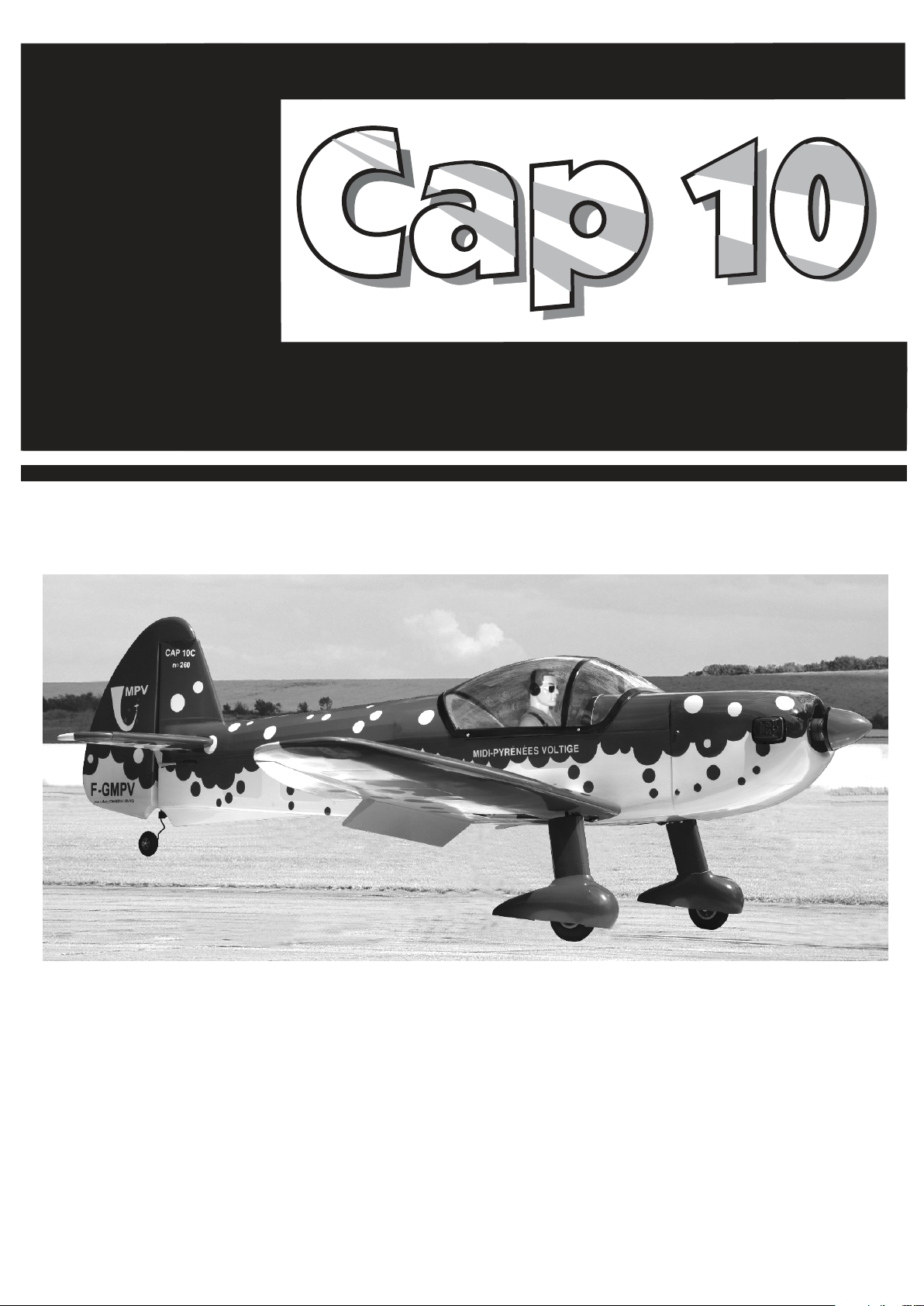
60 Class
2-cycle engine
90 Class
4-cycle engine
AEROBATIC MODEL
INSTRUCTION MANUAL / MONTAGEANLEITUNG
RADIO CONTROLED ALMOST READY-TO-FLY ENGINE POWERED ALL BALSA PLANE
SPECIFICATION TECHNISCHE DATEN
Wingspan approx. 1500mm
Fuselage lenght approx 1205mm
Electric Motor 870 Watt (PULSAR 60)
Glow Engine .61 2T / .91 4T
Radio 5 Channel / 6 Servos
Spannweiter ca. 1500mm
Lange ca. 1205mm
Elektroantrieb 870 Watt (PULSAR 60)
Verbrennerantrieb 10cc 2Takt / 15cc 4Takt
Fernsteuerung 5 Kanal / 6 Servos
Page 2
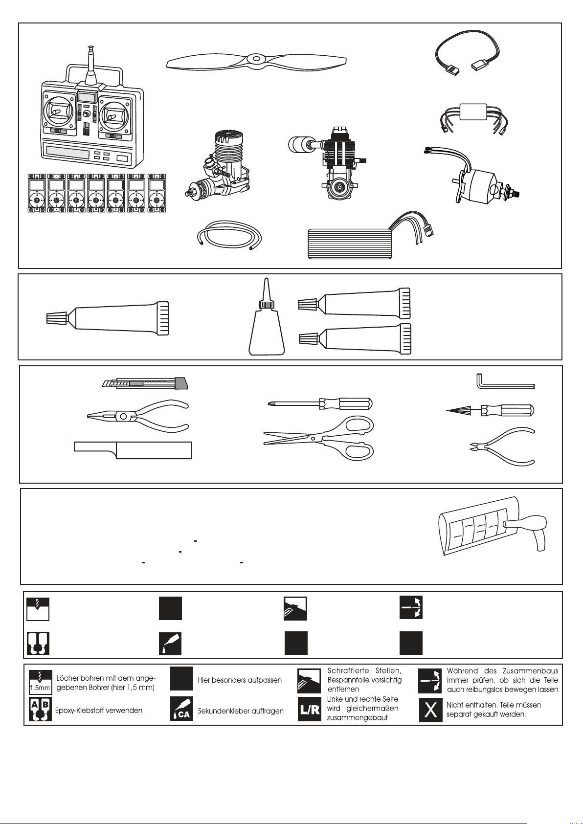
REQUIRED ITEMS / Zum Betrieb wird benotigt
Minimum 6 channel radio
for airplane with 7 servos
.Motor control x1 .Aileron x 2
.Flap x 2 .Elevator x1 .Rudder x1
GLUE /
KLEBSTOFF
SILICON
Silicon sealer
12x6 for .58 - 2 cycle engine
12x7 for .61 - 2 cycle engine
12x7 for .70 - 4 cycle engine
14x6 for .91 - 4 cycle engine
.58 ~ .61 - 2 cycle
Silicone tube
Cyanoacrylate
Glue
CA
.70 ~.91 - 4 cycle
EPOXY A
EPOXY B
Extension for aileron
servo.(x2)
ESC 80A
Motor Brushless
870Watt (PULSAR 60)
Li-Po Battery
LEMONRC 4500 - 18.5v
Epoxy Glue ( 5 minute type)
Epoxy Glue (30 minute type)
Hobby knife
Phillip screw driver
Hex Wrench
Needle nose Pliers
Scissors
Sander
.........................................................
.........................................................
.........................................................
.........................................................
.........................................................
.........................................................
.........................................................
.........................................................
.........................................................
.........................................................
.........................................................
Wire Cutters
Masking tape - Straight Edged Ruler - Pen or pencil - Rubbing alcohol - Drill and Assorted Drill Bits
If exposed to direct sunlight and / or heat, wrinkles can appear. Storing the model in a coll
place will let the wrinkles disappear. Otherwise, remove wrinkles in covering film with a hairdryer, starting with low temperature. You can fix the corners by using a hot iron.
Bei Sonneneinstrahlung und / oder Warme kann die Folie erschlaffen bzw. Falten entstehen.
Verwenden Sie ein Warumluftgeblase (Haartrockner) um evtl. Falten aus der Folie zu
bekommen. Die Kanten konnen Sie mit einem Bugeleisen behandeln. Nicht zuviel Hitze
anwenden
Drill holes using the stated
1.5mm
size of drill
(in this case 1.5 mm Ø)
A
B
Use epoxy glue
Take particular care here
!
Apply cyano glue
CA
Hatched-in areas:
remove covering
film carefully
Assemble left and right
L/R
sides the same way.
X
Awl
Check during assembly that these
parts move freely, without binding
Not included.
These parts must be
purchased separately
!
Read through the manual before you begin, so you will have an overall idea of what to do.
CONVERSION TABLE
1.0mm = 3/64”
1.5mm = 1/16”
2.0mm = 5/64”
2.5mm = 3/32”
3.0mm = 1/8”
4.0mm = 5/32”
5.0mm = 13/64”
6.0mm = 15/64”
10mm = 13/32”
12mm = 15/32”
15mm = 19/32”
20mm = 51/64”
25mm = 1”
30mm = 1-3/16”
45mm = 1-51/64”
Page 3
1- Servo installation / Servoeinbau
L/R
Plastic control horn
BOTTOM VIEW
Unteransicht
2x20mm screw
2mm
Plastic back plate
BOTTOM
Plastic control horn
2x20mm screw
2x20mm screw
2mm
............................4
2x20mm screw
.......................8
Linkage Stopper set
......................2
X
Aileron servo
extension cord
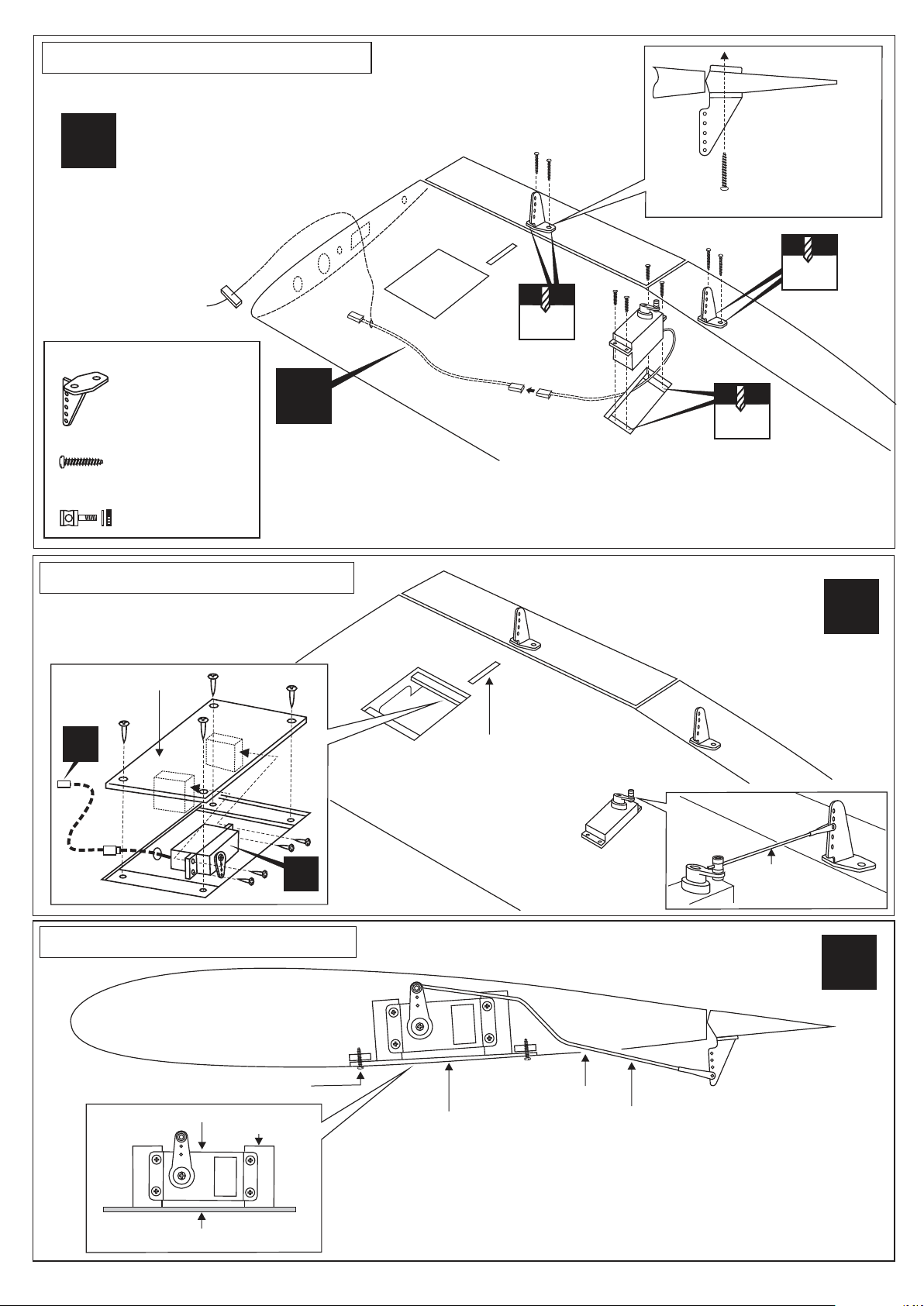
1-When you are satisfied with the alignment of the control horn mark the mounting hole
positions with a felt tipped pen or a pencil.
2-Remove the control horn and drill two 2mm (5/64”) holes through the ailerons and flaps.
3-Attach the control horn using two 2x20mm screw and a back plate.
2- Servo installation / Servoeinbau
Flap servo hatch
(plywood)
2x10mm
screw
X
Flap push rod exit
BOTTOM VIEW
Unteransicht
1.2mm
L/R
X
3- Servo installation / Servoeinbau
2x10mm screw
Flap servo
Servo mount
Flap servo hatch
Aileron servo
Aileron
push rod
TOP
Flap servo hatch
1- Place the flap servo onto the servo mounts and secure it in place using
the four screws included with the servo.
2- Install the flap push rod connector onto the hole in the flap servo arm
and insert the push rod through the push rod connector.
3- Place the flap servo hatch in its mount and secure it in place using four
2x10mm screws.
CAUTION: one of the flap servos is revert servo
L/R
Push rod exit
Flap push rod
Page 4
4- Wheel pants installation / Fahrwerkseinbau
Wooden dowel
L/R
Wooden dowel
CA
CA
2
1
“L”
BOTTOM VIEW
Unteransicht
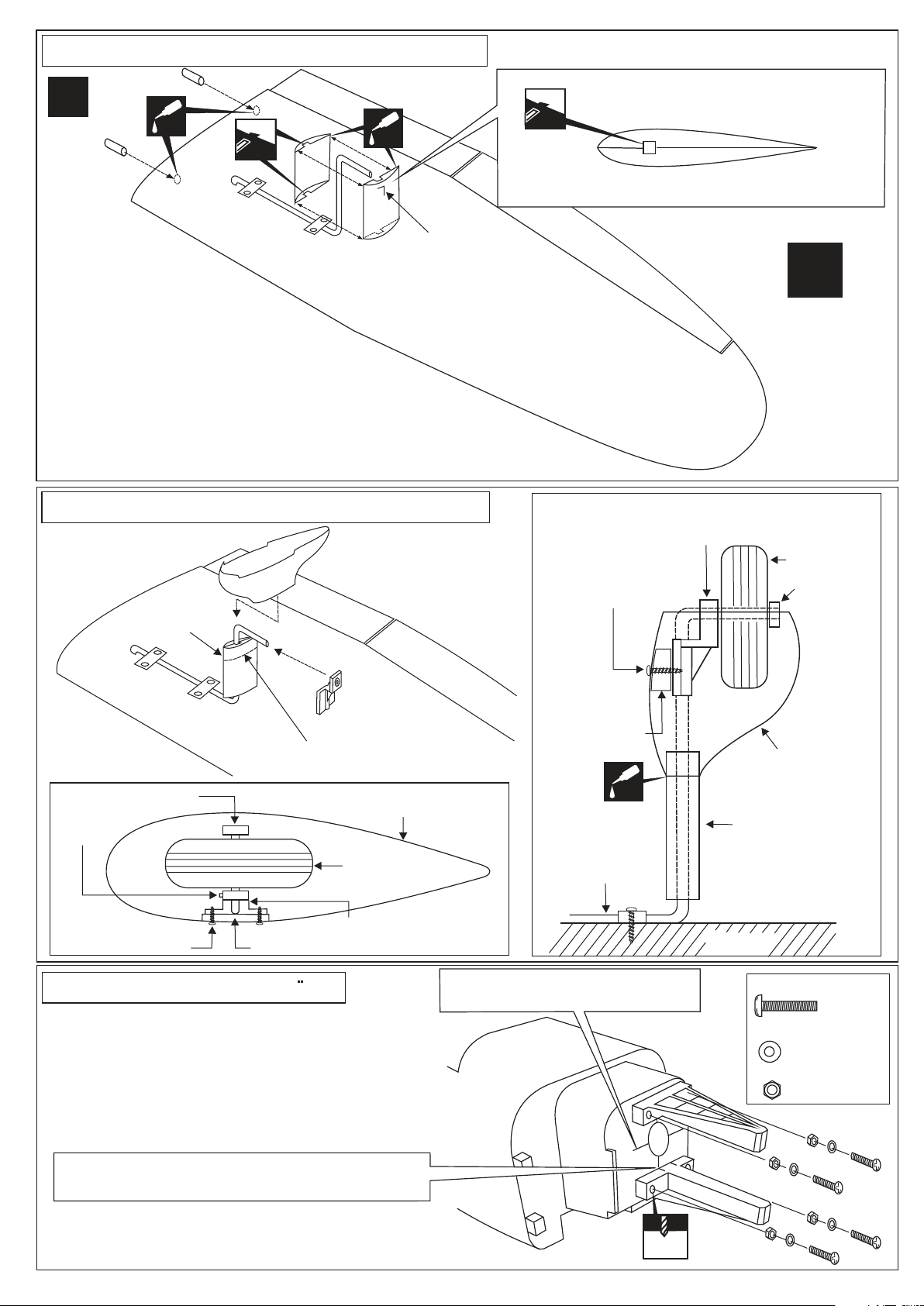
1- Position the landing gear and strap as
show. Using the four 3x10mm screws, fasten
the landing gear to the bottom of the wing.
2- Cut away two holes on the top and
bottom of the right and left ABS gear cover
for the landing gear exit
3- Fit all ABS gear cover in place (L with L and R with R) and secure them
with CA glue
5- Wheel pants installation / Fahrwerkseinbau
“R”
For left wing
For right wing
FRONT
FRONT VIEW
TOP VIEW
Right ABS gear cover of “L” set
REAR
Left ABS gear cover of “L” set
L/R
Vorderansicht
BOTTOM VIEW
Unteransicht
ABS gear cover
3
Fiber glass wheel pant
4
Nylon gear strap
CAUTION: Push down the wheel pant
to this line.
Stopper
3mm screw
(black)
3x12mm screw
Wooden block
6- Engine mounts / Motortrager
1- Set the engine on the engine mounts
2- Place the engine mounts with the engine to the
fire wall and secure it with tittle CA glue.
3- Using a pencil or felt tipped pen, mark the engine
mounting plate where the four holes are to be drilled
4- Remove the engine and drill a 11/64” (4.3mm)
hole through the fire wall at each of the four marks
made in Step 3 above.
Fiber glass wheel pant
Wheel
Nylon gear strap
BOTTOM VIEW
Nylon gear strap
3x12mm
screw(2)
6
Wooden block
CA
5
Landing gear
CAUTION: Align the engine center
with fire wall marked line
Wheel pant
ABS gear cover
WING
4mm screws
4mm washer
4mm nut
Wheel
7
Stopper
8
..........4
...................4
...................4
CAUTION: Align the mark on both mounts with the
center mark on the fire wall
CAUTION: Engine thrust on fire wall is aleady adjust
at factory
4.3mm
Page 5
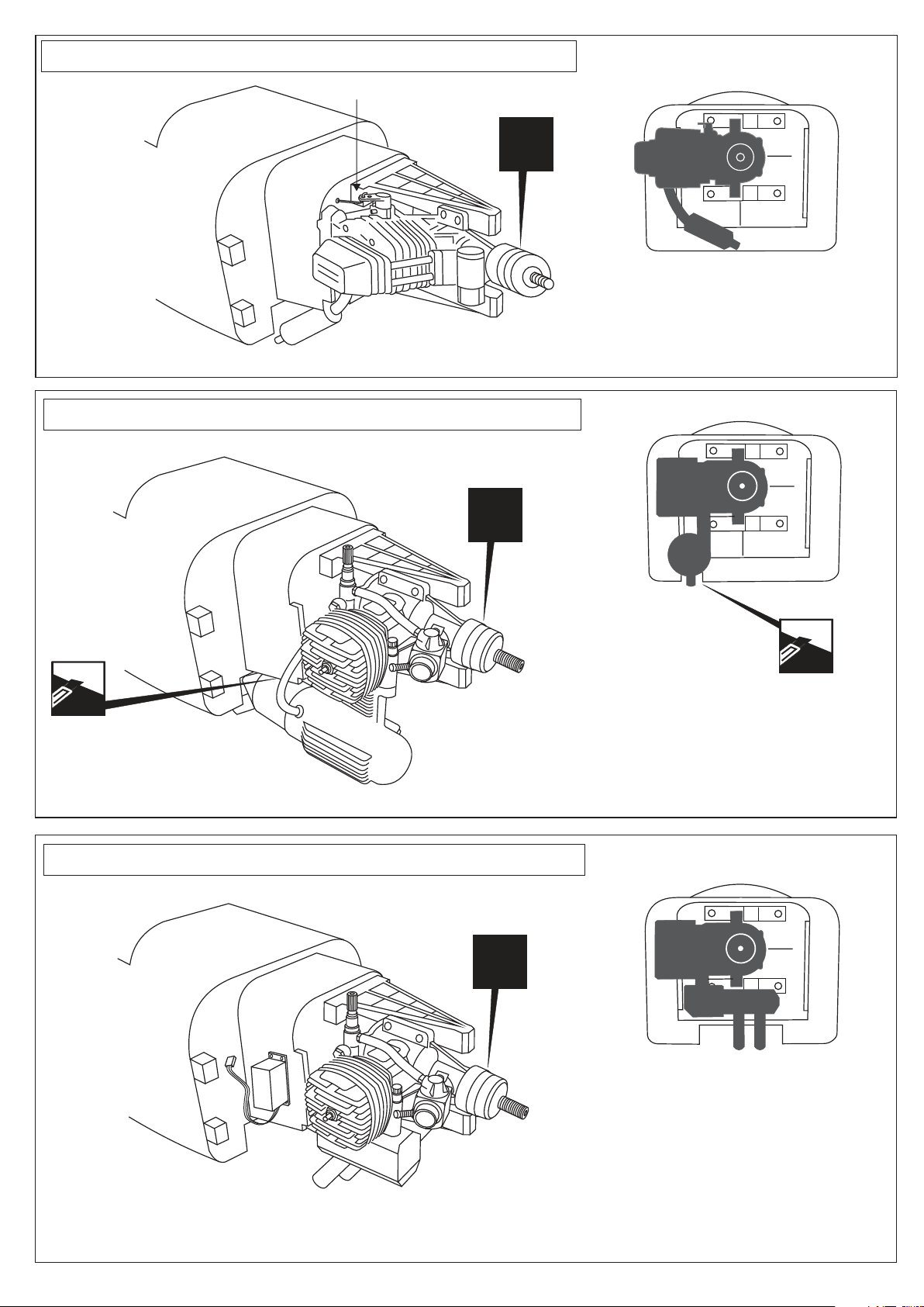
7- Four-stroke engine installation / Einbau Viertarktmotor
Throttle push rod
Engine
X
Secure the engine to the engine mounts using fous 3x25mm screws and nuts
8- Two-stroke engine installation / Einbau Zweitarktmotor
Engine
X
FRONT VIEW
In case of four-stroke engine
Trim the fire wall so that
your muffler doesn’t touch
with a knife or Dremel
9- Two-stroke engine installation / Einbau Zweitarktmotor
Engine
Secure the engine to the engine mounts using
fous 3x25mm screws and nuts
X
Trim the fire wall so that
your muffler doesn’t touch
with a knife or Dremel
FRONT VIEW
In case of two-stroke engine
Two-stroke engine with manifold
FRONT VIEW
In case of two-stroke engine
Page 6
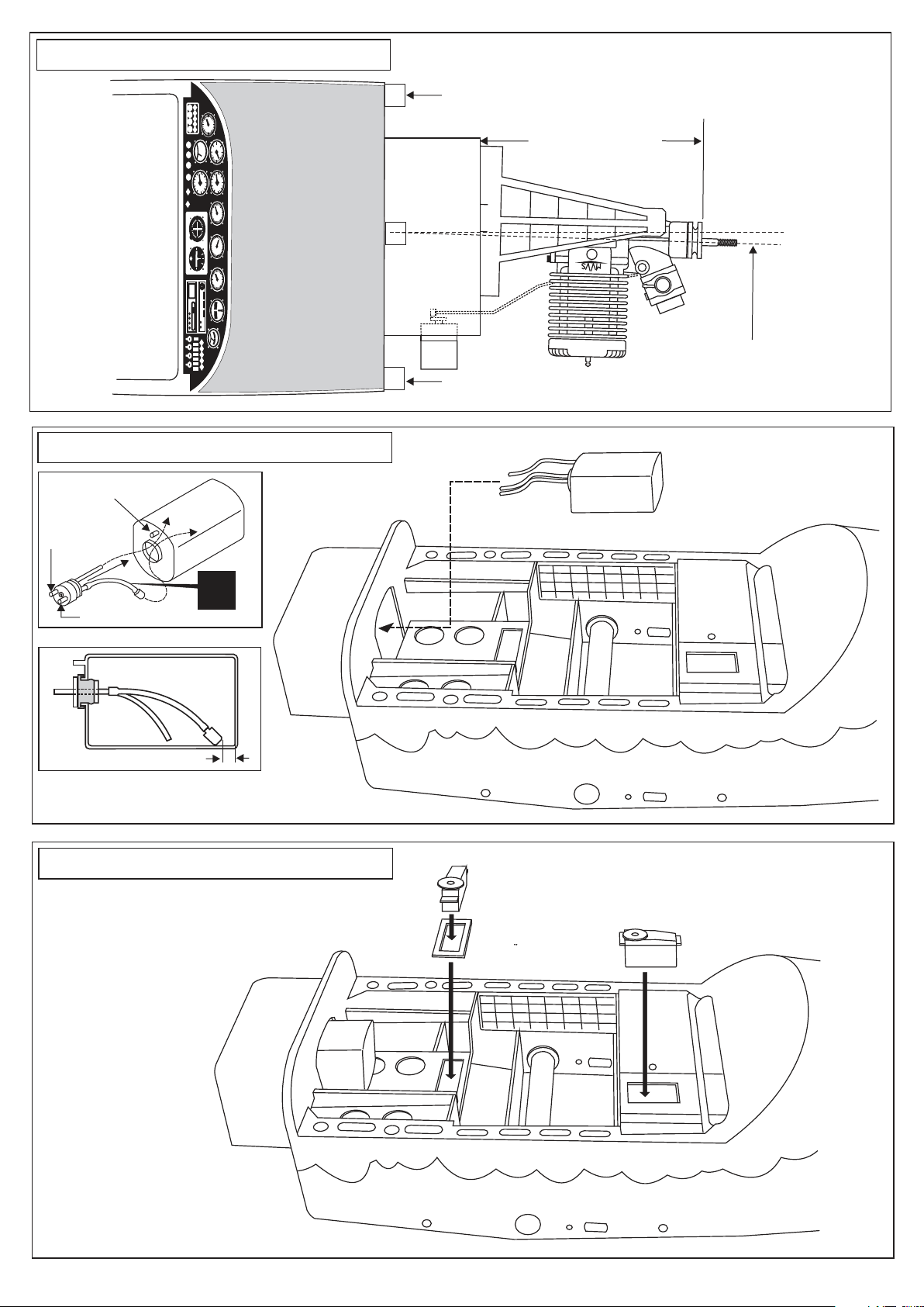
10- Engine installation / Motoreinbau
60
80
40
180
100
160
120
140
8
L
6
H
50
10
4
20
40
2
30
4
4
6
6
2
2
8
8
0
0
10
10
-2
-2
12
-4
12
-4
6
8
4
18
10
12
9
16
12
E
15
14
6
18
3
S
N
21
39
24
36
27
W
33
200
300
60
400
600 100
500
60
80
40
180
100
160
120
140
R
L
BAT
TOP VIEW
Cowling mount
Cowling mount
Draufsicht
118 ~ 122mm
6.5
Engine thrust on balk head
is already adjust at factory
11- Fuel tank installation / Tankeinbau
To muffler
Filler tube
X
To engine
5/32”(4mm)
After confirming the direction . Insert
and tighten the screw.
12- Servo installation / Servoeinbau
NOTE: Place of the throttle servos
may be change depend of engine.
(Four-stoke or two-stroke engine)
Servo mount
Servohalterung
Push the fuel tank forward until
there are no gaps between the
tank and firewall.
Throttle servo
Drosselservo
Elevator servo
Hohenruderservo
Page 7
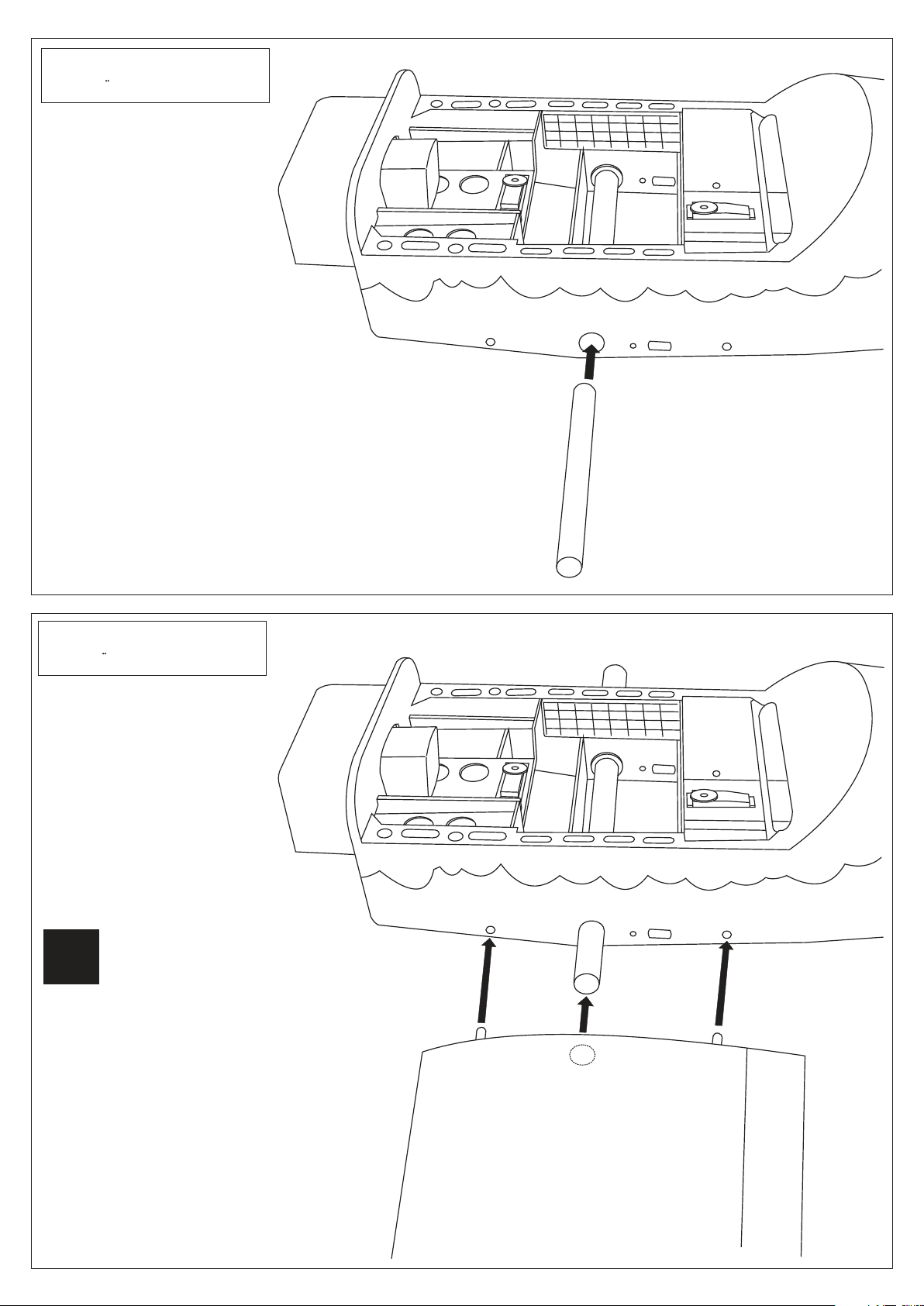
13- Joining the wing
Flachenverbindung
TOP VIEW
Draufsicht
Aluminum tube
14- Joining the wing
Flachenverbindung
TOP VIEW
L/R
Asemble the Left and Right wing
the same way.
Draufsicht
Page 8
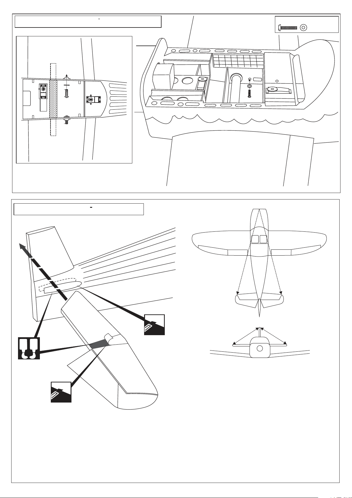
15- Joining the wing / Flachenverbindung
TOP VIEW
Draufsicht
RIGHT WING HARVEST
LEFT WING HARVEST
4mm screws & washer
......2
16- Horizontal Tail / Hohenleitwerk
A
B
Cut away only
the film
TOP VIEW
Draufsicht
A A’
B
B’
A = A’
B = B’
Warning: Securely glue together. If coming of during
Cut away only
the film
1- Trial fit the horizontal stabilizer in place
2- Using a pencil, trace around the vertical stabilizer where it meets the fuselage. (both sides).
3- Remove the horizon stabilizer from the fuselage.
4- Using a sharp hobby knife, cut away the covering inside the lines which were marked in step 2. Do NOT cut into the
wood as this will affect the structural integrity of the stabilizer
5- Using a mixing stick, spread the epoxy on the horizontal stabilizer and fuselage where it meets the horizontal stabilizer.
6- Insert the horizontal stabilizer into the fuselage and secure it in place using masking tape and allow the epoxy to cure
completely. Using rubbing alcohol and paper towel, clean the excess epoxy.
flights, you lose control of your plane which leads
to accidents!
Page 9
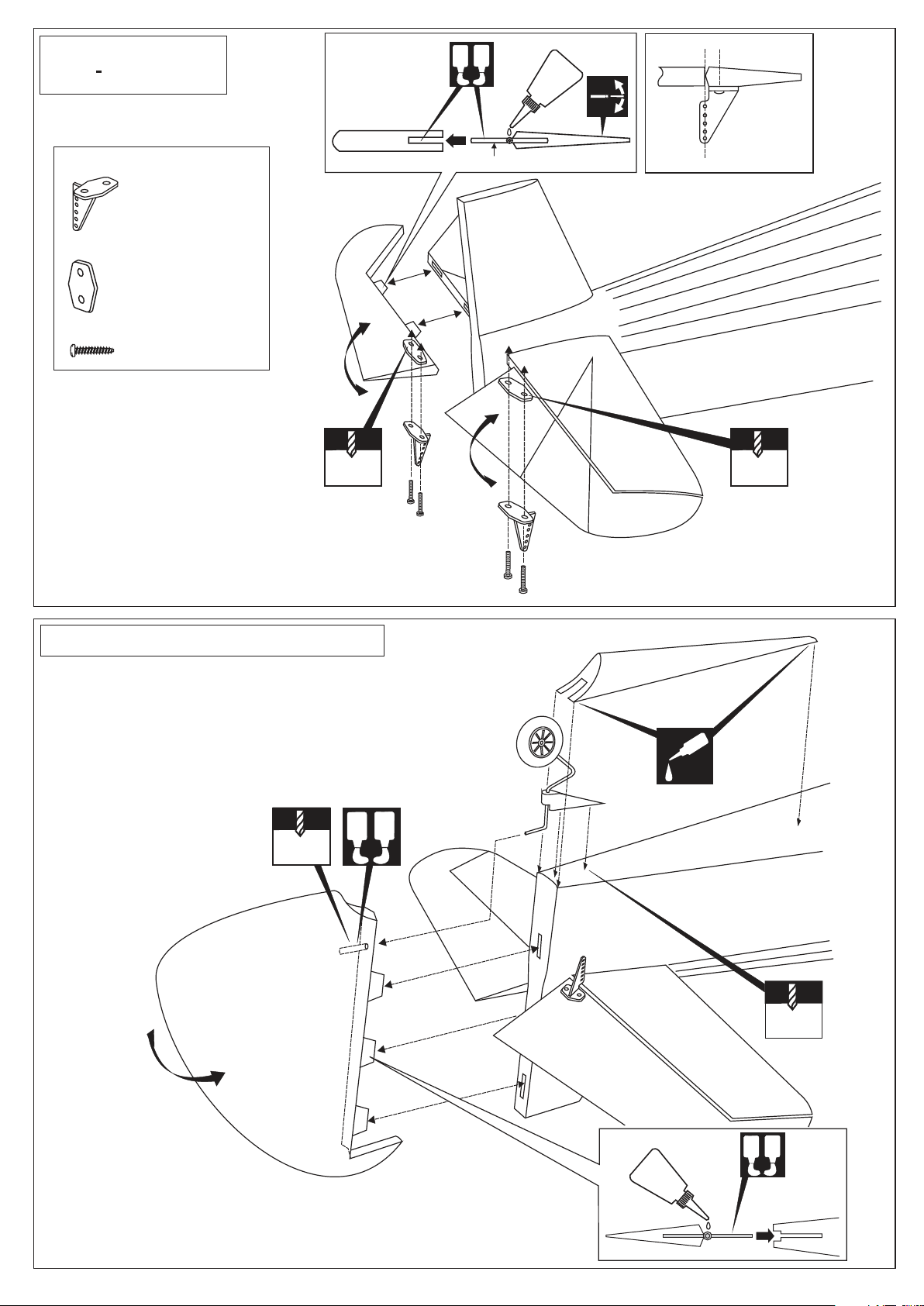
17- Horizontal Tail
Hohenleitwerk
Apply 5 min.
Epoxy both the
top and bottom.
A
B
10mm
Plastic control horn
............................2
Plastic back plate
...........................2
2x20mm screw
.......................4
When you are satisfied with the
alignment of the control horn mark
the mounting hole positions with a
felt tipped pen or a pencil.
Remove the control horn and drill
two 2mm (5/64”) holes through the
elevator
Insert the elevator push rod into the
elevator control horn. Attach the elevator control horn using two 2x20mm
screw and a back plate.
STABILIZER
Hinge
ELEVATOR
2mm 2mm
WARNING! Securely glue together. If coming off
during flights, you lose control of your airplane
which leads to accidents !
18- Vertical stabilizer / Seitenleitwerk
1- Attach the tail gear mounting plate on the fuselage bottom
with 3x10mm self tapping screws
2- Trial fit the rudder in position, mar the mounting hole position
for the tail gear with a felt tipped pen or a pencil.
3- Remove the rudder and drill 2mm (5/64”) hole as shown.
4- Put the epoxy glue in the hole of rudder. Push the rudder in
place
A
B
2mm
CA
2mm
WARNING! Securely glue together. If coming off
during flights, you lose control of your airplane
which leads to accidents !
Petroleum jelly
A
B
Apply 5 min.
Epoxy both the
top and bottom.
Page 10
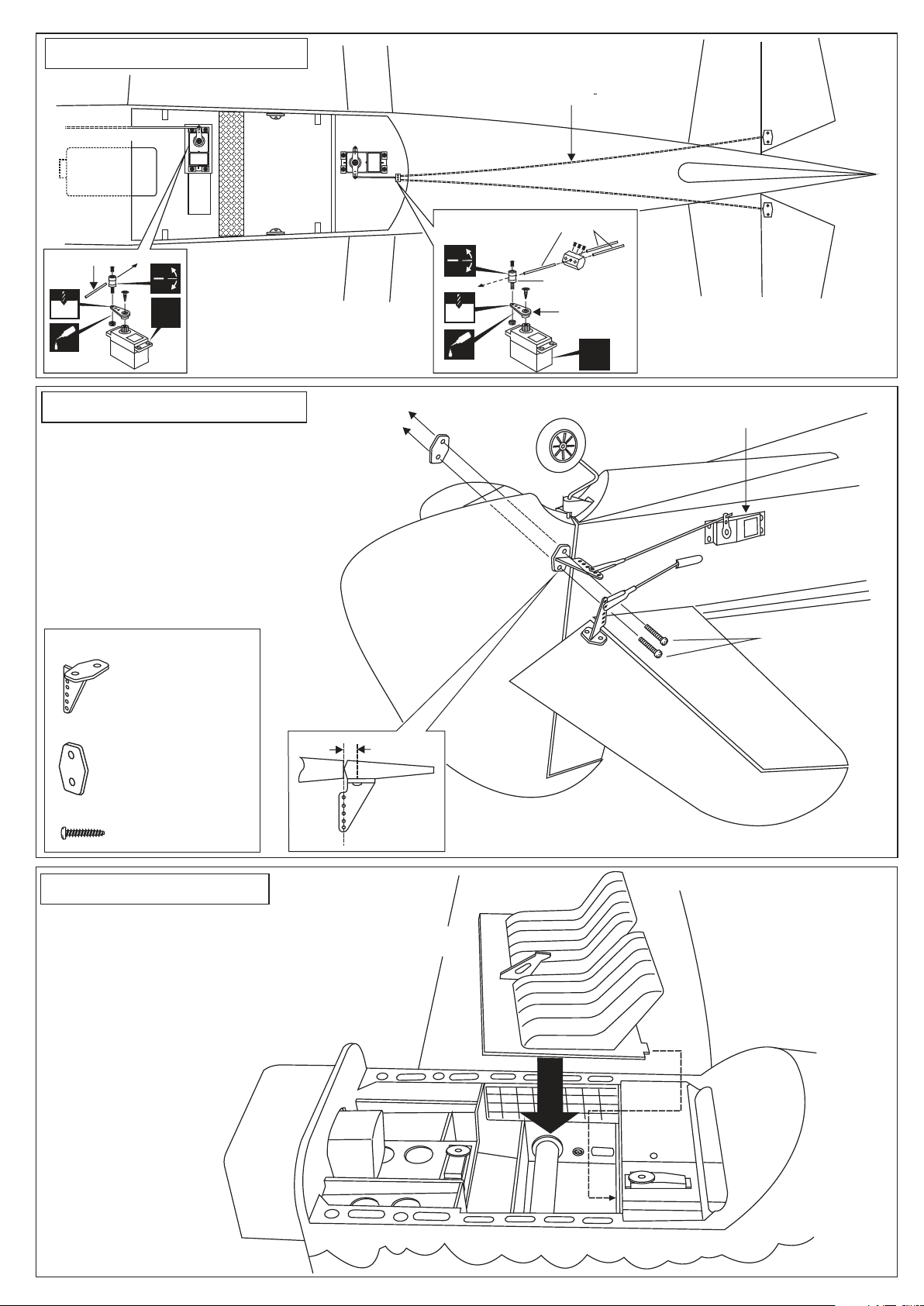
19- Linkages / Anlenkungen
Throttle pushrod
Tank
TOP VIEW
Draufsicht
Elevator pushrod
Rudergestange
Elevator push rod
Throttle push rod
2 mm
CA
X
20- Linkages / Anlenkungen
When you are satisfied with the
alignment of the control horn, mark
the mounting hole positions with a
felt tipped pen or a pencil.
Remove the control horn and drill
two 2mm (5/64”) holes through the
rudder
Insert the rudder push rod into the
rudder control horn. Attach the rudder
control horn using two 2x25mm screw
and a back plate.
Plastic control horn
............................1
2 mm
CA
Connector
Linkage stoper
Included with the
radio set
X
Rudder servo
2x25mm screw
Plastic back plate
...........................1
2x25mm screw
.......................2
21- Cockpit
TOP VIEW
Draufsicht
10mm
Magnetic cockpit deck
Page 11
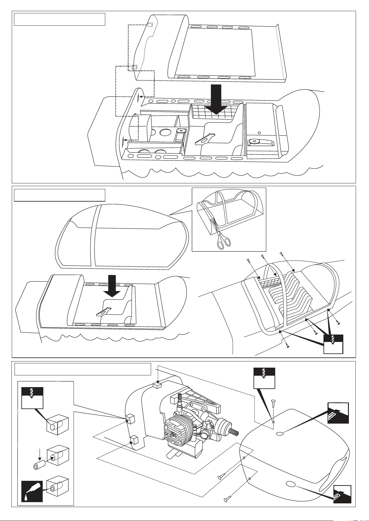
22- Cockpit / Kabinen
TOP VIEW
Draufsicht
23- Cockpit / Kabinen
Magnetic hatch
TOP VIEW
Draufsicht
24- Cowling installation / Motorhaube
5mm
2x10mm screw
3
1
5
2
2x10mm screw
3mm
Drill holes for needle
valve, exhaust pipe
and glow-plug.
4
1.5mm
Fuel tube or
nylon tube
CA
3x10mm self tapping screw
Page 12
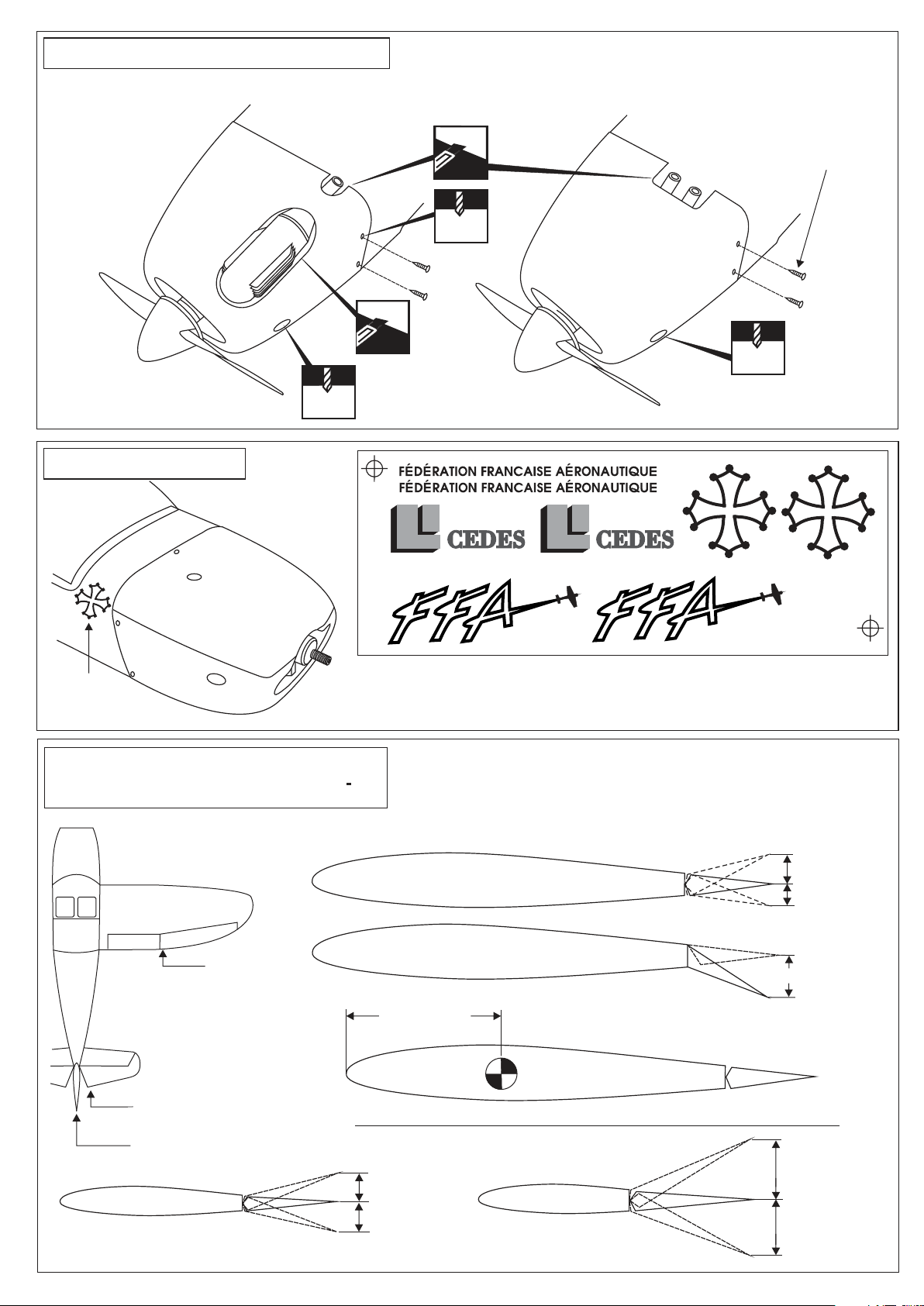
25- Cowling installation / Motorhaube
Trim the cowl with a knife or Dremel so that your engine and muffler don’t touch
BOTTOM VIEW
Unteransicht
Fix the cowling with the 3x10mm self tapping screws on the cowling mounts.
3x10mm self tapping screw
3mm
26- Decor / Aufkleber
Sticker
27- Balance and control range
Schwerpunkt - Ruderausschlage
Drill holes for needle valve
and glow-plug
Adjust the travel of each control surface to the values
in the diagrams these values fit general flight capabilites.
Readjust according to your needs and flight level.
Drill holes for needle valve
and glow-plug
VQ / CAP-10 VERSION 3
Position for
right diagram.
Position for right diagram.
Position for right diagram.
ELEVATOR CONTROL RANGE
AILERON CONTROL RANGE
FLAP CONTROL RANGE
2.9 ~ 3”
(75 ~ 78mm)
19/32”(15mm)
25/64”(10mm)
51/64”(20mm)
CG
NEVER FLY BEFORE CHECKING THE CG’S REQUIRED POSITION.
1.7”~1.9”
51/64”(20mm)
51/64”(20mm)
RUDDER CONTROL RANGE
(45 ~ 50mm)
1.7”~1.9”
(45 ~ 50mm)
 Loading...