

Page 1
VVPPrrootteecctt VVPPTTZZ550000
IInnddoooorr SSppeeeedd DDoommee
User’s Manual
and
Operating Instructions
Page 2

1
Safety Attention Notes
◎Please read the instructions thoroughly before installing or operating the unit.
◎Please do not put the machine on an unstable table or mounting bracket.
◎Please prevent all liquids or other contaminating material from entering into the dome
housing.
◎When connecting to the power source, please follow all electric safety standards and only
use the power supply designated for this device. The VPTZ500’s RS-485 and video signal
uses TVS technology to protect it from strong electric surges. This technology prevents
damage to the device resulting from impulse signals such as lightning strikes or surges
under 500W power. Allow for enough distance between the RS-485 and video signals and
high-voltage equipment or cables during the transmission process. Please do not power the
unit until all connections are secure and installation is complete.
◎Avoid shooting very bright objects directly into the camera’s CCD (such as the sun or light
fittings).
◎ When the machine is not operating properly, do not casually repair it. Refer to the
instructions for information about how to service or repair your VPTZ500.
◎ Please protect the unit against extremes of vibration, pressure or dampness while
transporting unit. Damage can occur from improperly packaging the unit while shipping.
◎Please only install the Indoor dome camera system in Indoor environments.
Page 3
2
Page 4
3
I. Introduction
Congratulations on purchasing our VPTZ500, an intelligent, high-speed dome camera with a
high-performance DSP camera and sophisticated zoom lens. It is an advanced technological
surveillance product combining an all-direction variable speed dome and digital decoder all in one unit. It
can aim quickly and scan continuously, making omni-directional and non-blind-spot monitoring into
reality. Additionally, it can quickly adapt to changing environments with its 18x optical and 12x digital
zoom with precise stepping motors. The advanced stepping motor technologies enable the dome to
rotate smoothly, respond sensitively and aim precisely. VPTZ500 dome camera has memorizing function
when the power cuts off, can auto resume to previous working status before the power cuts off. Use the
high-performance VPTZ500 “When it Counts.”
All of the features make the intelligent high-speed dome camera fit for a wide range of applications such
as intelligent building, bank, street of city, airport, station etc.
II Technical Data
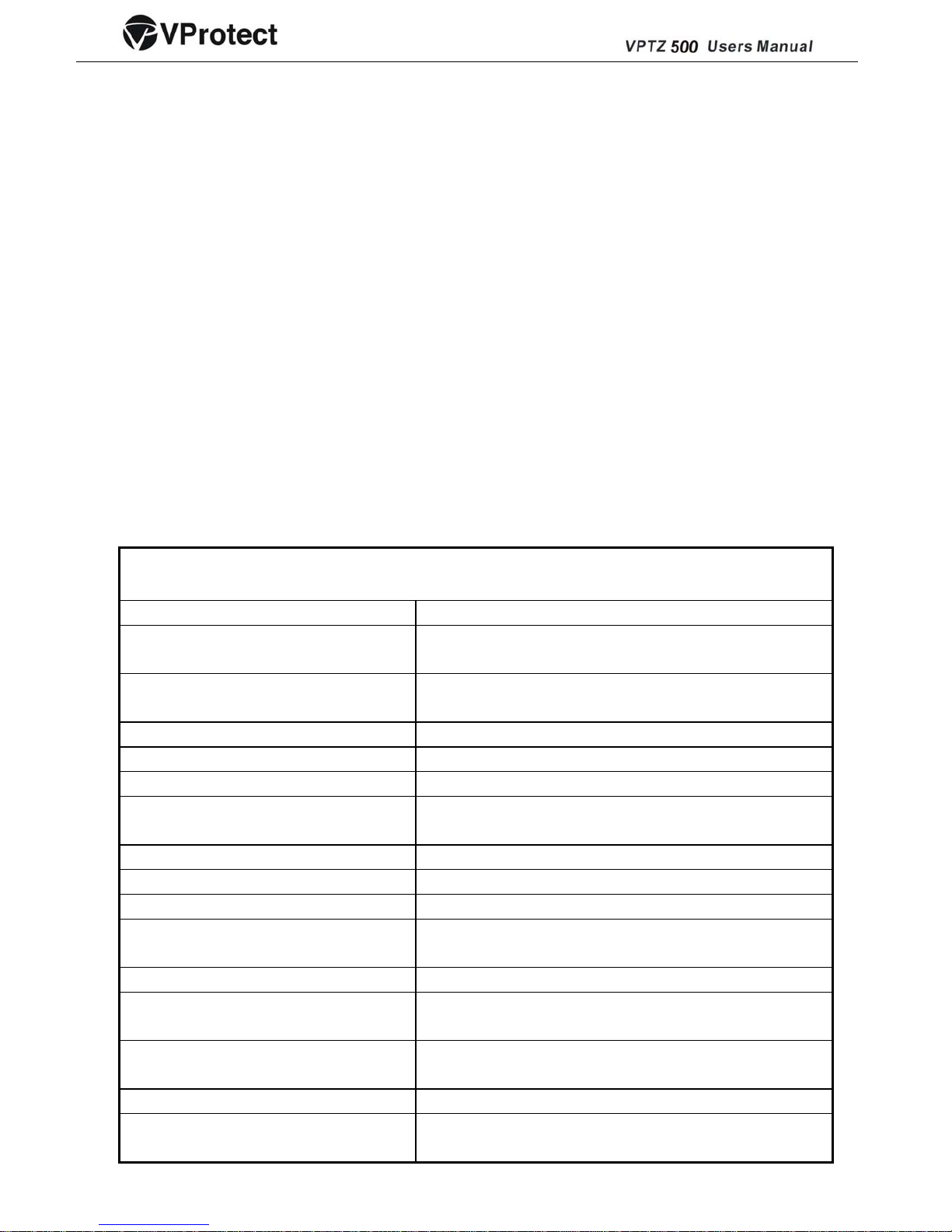
2.1. Technical Parameter of Intelligent High-speed Dome:VPTZ500
Model Indoor Day/Night Speed Dome
Power Supply AC24V±5%
Operating temperature
Indoor: 0℃~+40℃ Indoor:﹣40℃~+60℃
Operating moisture
≤95%
Power consumption 20W
Communication RS485 bus
Communication transmission speed 1200/2400/4800/9600bps
Horizontal rotation speed
0.4°-280°(1-64 grade shift gears)
Horizontal rotation range 360° unlimited rotation
Tilt rotation range 90°
Auto f lip Rotates 180° when camera tilts to the vertical position
Auto zoom speed control Control speed auto-adjusted according to zoom length
changing
2 points scan Can set freely
2 points scan speed
1-64 grade available
Dwell time(2 points scan)
1-60s available
Preset Positions 128 pcs
Running to preset speed:
1-64 grade available,0.4°-280°
Page 5
4
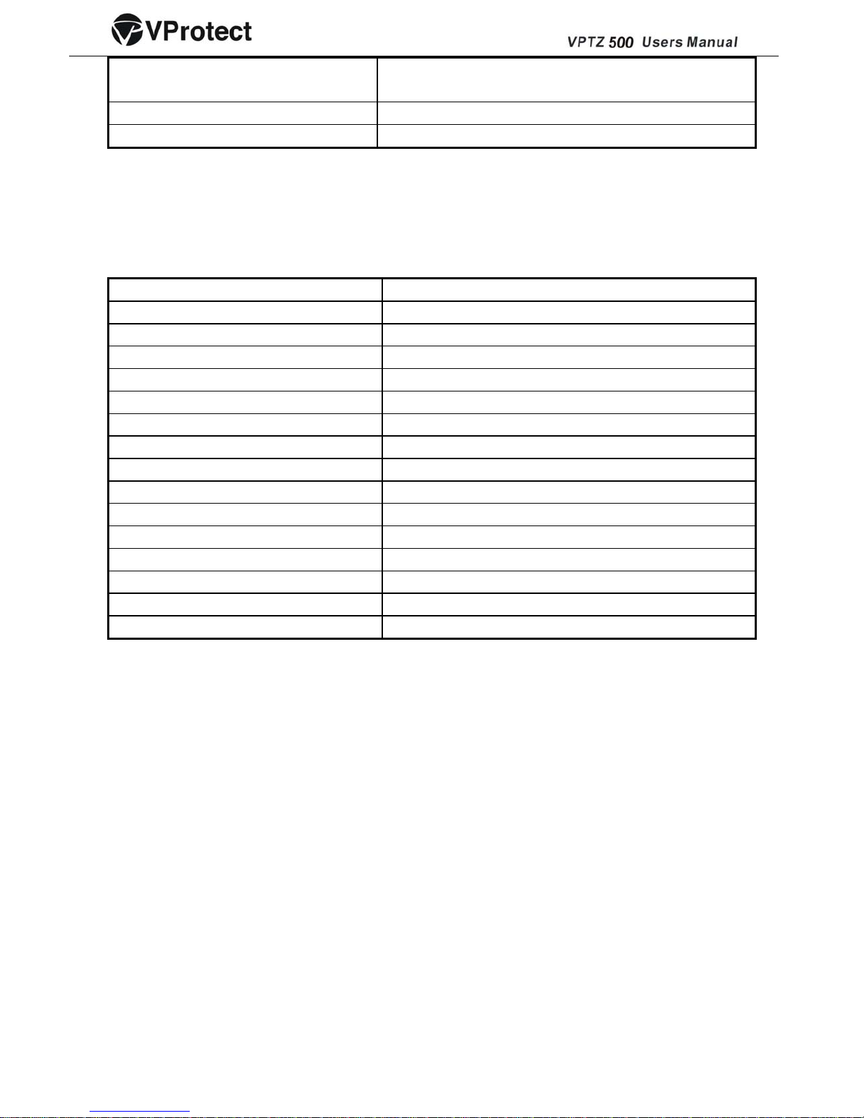
Dwell time at preset position
1-60s available
Cruise Tour: 8 group
Cruise Points Qty per cruise group 16 preset positions
2.2.
Camera Parameter for Intelligent High-speed Dome: VPTZ500 (Built in SONY Camera).
Mode ¼” Sony Exview (Day/Night) CCD
Sync Internal/ external
Scan 2:1 Interlace
Resolution >480 lines
Minimum illumination 0.7lux
Iris Auto/manual
Focus Auto/manual
Zoom 216 X (Optical 18x; Digital 12x)
Focal length f=4.1-73.8mm, F=1.4-3
Angle of view 47°(wide) , 2°(Tele-)
Backlight compensation backlight compensation
White balance Auto
Gain Auto
Signal PAL/NTSC
S/N ratio >55dB
Video signal output 1.0±0.2Vp-p
III Setting, Installation, Connection
3.1 Dome Address, Transmission Speed, Protocol Setting
Before the dome is installed, the communication protocol, baud rate and dome address, should be
confirmed. Set the code switch, keeping the setting consistent with the control system. The relative code
switch site and connecting wire are diagramed below for reference.
Page 6
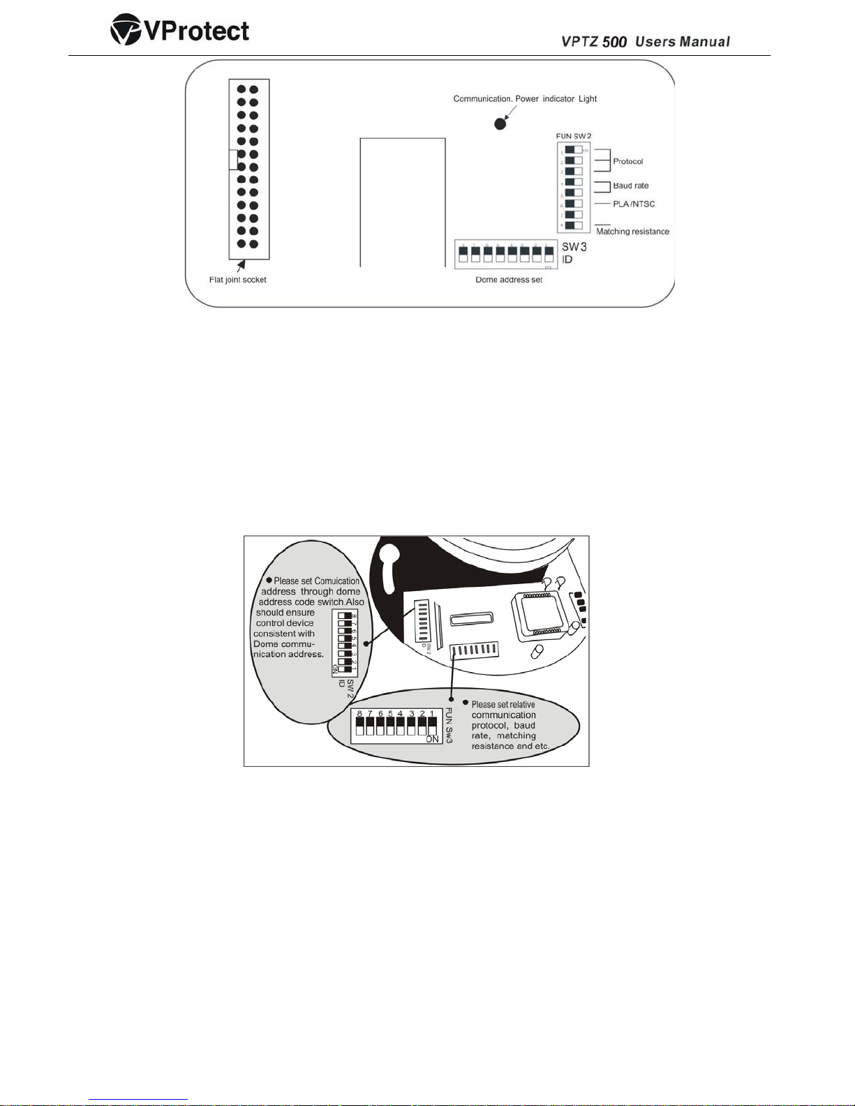
3.1.1 VPTZ500 Dome Camera Address Setting
The address code for the VPTZ500 should be properly set before use to ensure accurate operating
order of the controller at the control center and to control many dome cameras. The address code is
made up of SW3 (8 bits) on PCB board. The 8 bits switch uses the 8421 binary coded decimal
system. The largest value is established at 256. 1 means ON status and 0 means OFF status.
Each dome address code and keyboard relative screen display mode is represented in the chart
below (see the following figure and the address/digits in following chart)
5
Page 7
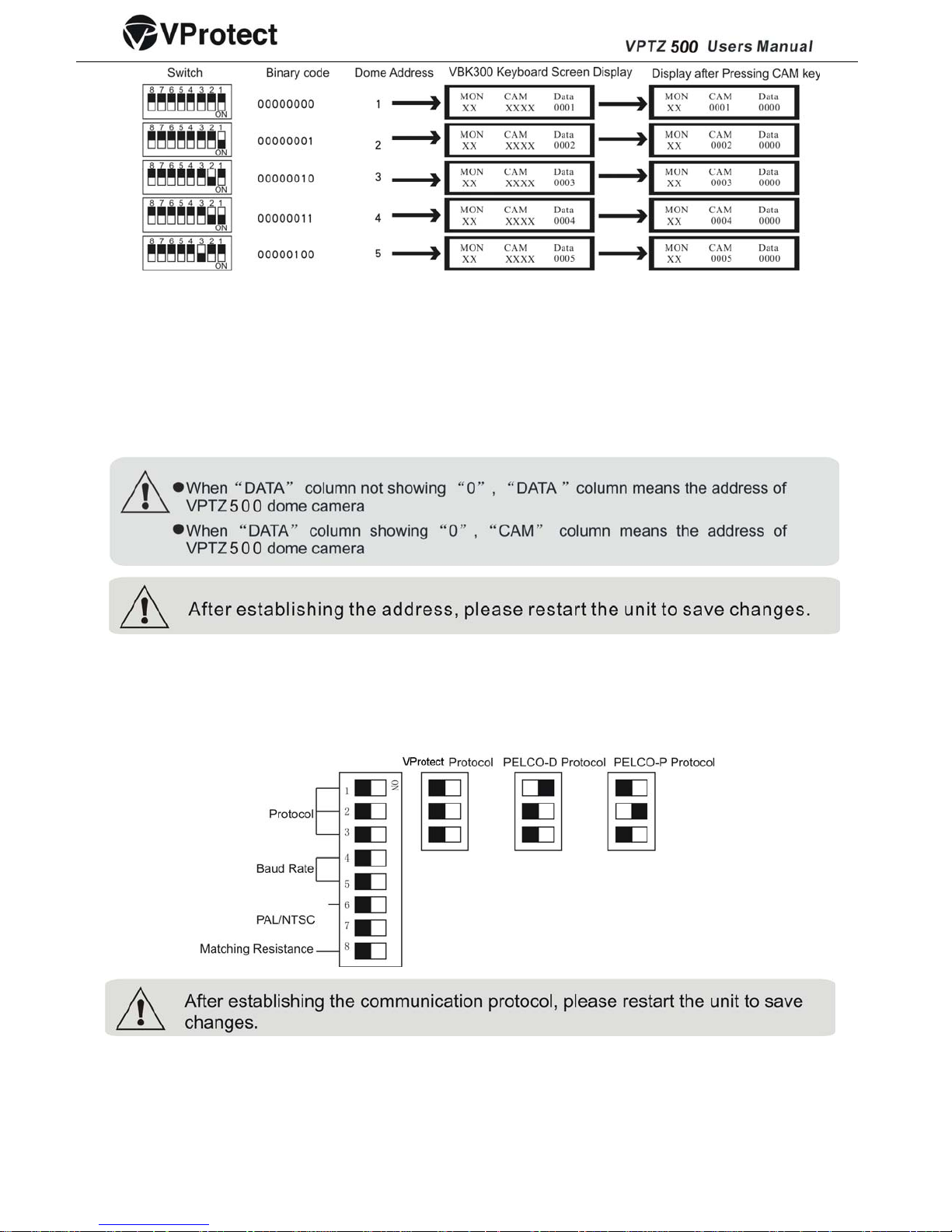
With reference to the above chart: When all code switches are under “OFF” status on VPTZ500, address
code is 1. When you input Numerical key No.1 on VKB300/VKB200 control keyboard, then press CAM
key for confirmation showing that set VKB300/VKB200 address as No.1 control address., At this time,
VKB300/VKB200 keyboard can control VPTZ500 dome camera(its control address is 0001). Other
address is to be set as above.
6
3.1.2 VPTZ500 Dome Camera Communication Protocol Setting -
The 1st, 2nd and 3rd bits in SW2 are used to set communication protocol (see following figure)
3.1.3 VPTZ500 Dome Camera Transmission Speed Setting(Baud Rate Setting)
The 4th and 5th
bits of SW2 on the PCB board are used to set the baud rate (see following figure).
The default baud rate setting is 9600.
Page 8
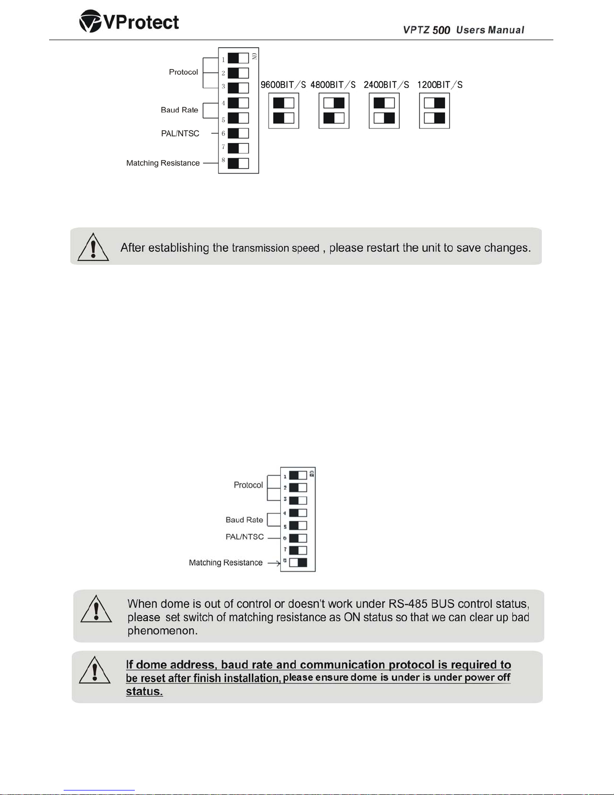
Baud Rate Options: 1200BIT/S 、2400BIT/S 、4800BIT/s、9600BIT/s
3.1.4 RS-485 Bus Matching Resistance
For central controlling, the matching resistance should be set for the device that is furthest away
from the controller. There is an end matching resistance switch on SW2. The 8
th
bit of SW2 shows
ON status (see chart below) which means the BUS matching resistance has been connected.
3.2 Installation, Connection
Attention!
1. Installation should only be handled by a qualified CCTV expert.
7
Page 9

2. For detailed connection information, please refer to silk-screen print instruction on PCB and
installation guide or manuals.
3. Because the dome is a high-grade optical unit, please never touch any of the optical components.
4. For a clear image, the dome cover should be cleaned periodically. When cleaning, position your
hand to hold dome’s outer loop to prevent finger sweat acidity from corrupting the surface of the
dome. If the dome is scratched, it will affect image quality. Therefore please use a soft dry cloth or
similar products to clean its outer surface. If the dust is heavy, you can use a neutral cleanser. Any
advanced furniture cleanser can be used to clean the dome exterior.
Installation Preparation
3.2.1 Installation Requirement-
Installation should be handled by a qualified service agent and should comply with all local
regulations, Service personnel should forecast potential problem such as falling objects, outer breach,
building vibration or other similar conditions.
Check for all necessary materials, and ensure if the selected installation location is suitable for the
VPTZ500.
3.2.2 VPTZ500 Indoor Hemisphere Dome Camera Recessed Installation
VPTZ500 Installation
ATTN: Installation locations should endure five times the total weight of the camera assembly (dome
camera, mounting bracket and mounting base) to avoid in shaken images. Installation ceiling
must be strong and has no peeling phenomenon.
A. Draw out center site of the hole on the ceiling against embedded upper housing sample
B. Use drill to make hole on the ceiling
8
Page 10

· Housing Installation
A Take out the housing from the carton, adjust the thickness of bolt reed more than that of ceiling.
B Stick 3 ring to housing, and install the upper housing in the round hole of the ceiling, connecting
flange edge with the ceiling surface closely.
C Use screwdriver to rotate the bolt of the ring, making the ring stick to the ceiling in order to
connecting flange edge with the ceiling surface closely.
Camera Module Installation
• Turn power supply off prior to installation.
• Loosen the two M5 screw on the bracket, which are located in the inner housing .
• Take the camera module from the packing carton, and check if connecting wire plugs are loose. Set
code switch of the dome camera.
• Secure the camera module (use one hand to hold stepping motor, preventing it from moving.). Insert
the wire terminal into the outlet on the end of camera module. Align two bar holes on the camera
module base with the two M5 bolt of the connecting bridge. Twist the camera module upward
ensuring the two M5 bolts reach the end of bar hole. Tighten the two M5 bolt to make camera module
fixed in the upper housing.
9
Page 11

Connection (Outer Connecting Wire)
Connect BNC video interface of dome camera with video wire (BNC) which is finished installing. Connect
power supply line with power line (AC24V) which have been set well.
Electricity
¾ Check the polarity of the plug and outlet, then check all connecting wires.
¾ Domes enter self-inspection, and make a horizontal 360° and tilt 90° rotation to test camera lens,
dome horizontal and tilt electronic& mechanical structure. Then carry out a replacement program
rotating to starting point. After the dome stops completely, the self-inspection is completed and
dome is ready to be controlled.
Dome Mounting
¾ Use soft cloth to wipe off dust and smudges of transparent dome cover, avoid scratching it
¾ Align two holes on the dome cover edge with the two connection points of the metal upper
housing( See Picture 1).
10
Page 12

.
IV.
VKB300/VKB200 Keyboard Control Use Instruction to VPTZ500 Dome Camera
Use the VKB300 keyboard controller to realize the complete potential of the VPTZ500 intelligent speed dome.
(The VKB300 keyboard control protocol is set as the default protocol for the VPTZ500.)
4.1Setting and Adjusting Preset Position
The Preset function is the dome’s default level angle, lean angle and camera focal length in EMS memory.
By using this saved parameter, the dome and camera can run to the preset positions when it is required.
Operator can save and adjust preset positions by using the VKB300/200 control keyboard; the VPTZ500
dome can support 128 preset positions.
4.1.1 Setting Preset Position
Adjust the VPTZ500 camera to the desired position using the VKB300/200 keyboard joystick/rocker
(including location, camera zoom, focus and iris), and then input the required preset position number.
The inputted preset position value No. is displayed at the bottom of the LCD “DATA” area. Press Shift +
Call, to confirm position. The preset position at “DATA” disappears showing that the preset position was
set successfully.
For example: Set No.1 preset position
1. In the Main Menu screen, Press CLR to Clear the data. The keyboard displays:
2. Enter the Preset Position Number you wish to set
Ex. Set Preset Position No. 1, the keyboard displays:
Displays the Preset Position
Number
(
1-128)
3. Adjust the VPTZ500 camera to the desired position including location, camera zoom, focus and
iris.
11
Page 13

4. Press Shift + Call for final confirmation.
4.1.2 View Preset Position
Use the VKB300/200 keyboard to view the preset position. (Preset positions are saved in advance).
Input the preset position you would like to view, Data area will display preset position number. Press
Call key, the dome will move to the target place.
For example: View No.5 preset position
1. In the Main Menu, Press CLR to clear the data.
2. Input the preset position you would like to view.
Example: View preset position No. 5
Displays the Preset Position
Number (1-128)
3. Press the CALL key. The dome will move to the Preset Position No. 5
4.2 Dome Pattern Tours
Pattern Tours are a key function of the VPTZ500 dome camera. You can layout the preset position order in
the pattern tours through our advanced program. Using the control keyboard you set the rotation speed for
each preset position and dwell time at each preset position. Only an outer command unit can transfigure the
VPTZ500 dome camera into a pattern tour program route.
4.2.1Preset Position Parameter Setting
VPTZ500 dome camera has the capacity to set up to 128 preset positions through the VKB300/200
keyboard. It can set a running speed at each preset position from 0.4/s to 280/s (1-64grades) and dwell time
from (1-60seconds).
Note: VPTZ500 can rotate at low speeds and at fast speeds. Its speed can be divided into 64 grades. 1 is
the lowest speed and 64 is the fastest speed.
12
Page 14

To get to the VKB300/200 keyboard Main Menu Press Exit until the screen displays:
1. In the Main Menu, Press the FUN key once. VKB300/200 Keyboard displays:
Press CLR to delete previous data. Input
required VPTZ500 address code XXXX
2. Enter the correct Speed Dome Unit and Press Enter.
Example: Preset Position for Speed Dome 3. VKB300/200 Keyboard displays:
Displays the Speed Dome
Address (1-1024)
3. Now the VKB300/200 Keyboard displays:
13
Preset position (1-128)
Running
speed
(
1-64)
Dwell time(1-60)
Press F1 key on the keyboard to move the cursor up and down
4. Press CLR key to delete previous data before programming to a new preset position.
5. Enter desired Preset Position and Press Enter.
6. Press F1 to get to Speed. Using the number keys enter the desired running speed.
7. Press F1 to get to Time. Using the number keys enter the desired dwell time.
For example: Set the running speed of preset position No. 6 as Grade 64 (fastest speed), dwelling time is 5
seconds. Set the running speed of preset position No.2 as Grade 10, dwelling time is 10seconds.
1. Press the FUN key once.
2. Press CLR to clear the data.
3. Input 06 (Note: Setting the Preset Position No. 6) press the Enter Key to Confirm.
4. Press the F1 key to move the cursor to Speed:00←
5. Input 64, press Enter
6. Press the F1 key to move the cursor to Time:00←
7. Input 05, press Enter
8. Press F1 to move the cursor back to 1.Position:001←
9. Press CLR to delete 0006
10. Input 02, press Enter
11. Press the F1 key to move the cursor to Speed:64←
12. Press CLR to delete 64
13. Input 10, press Enter
Page 15

14. Press the F1 key to move the cursor to Time:05←
15. Press CLR to delete 05
Input 10, press Enter
4.2.2 Pattern Tours Setting
VKB300/200 keyboard can set pattern tour groups for the VPTZ500 speed dome camera. Before setting
the Pattern Tours please set all preset positions in advance. If the preset positions are not set the pattern
tour will default to the pattern tour parameter. Note: VPTZ500 can set 8 cruise groups.
1. Press the FUN key once, VKB300/200 keyboard displays:
Displays the Speed Dome
Address (1-1024)
2. Enter the correct Speed Dome Unit and Press Enter.
Example: Set Pattern Tour for Speed Dome Unit 02. VKB300/200 Keyboard displays:
Displays the Speed Dome
Address (1-1024)
3. Press the FUN key once, now the VKB300/200 keyboard displays:
Displays the Group Number
(1-8)
4. Input a Group number using the number keys, press Enter, VKB300/200 keyboard displays:
5. Input desired Pattern Tour for the Group.
Example: Desired pattern tour is Preset Position No. 1 – 2 – 3 – 4 – 5 – 6
The VKB300/200 keyboard displays:
6. Press Enter to confirm Pattern Tour.
Remark: When completed, Press F2 to close and exit. To Start the Scan: In the Main Menu enter the
Group Number and Press SCAN.
¾ This dome can set 8 cruise group, Max 16 cruise points/each group(1-128 points at any preset
position.
¾ Set preset position at the cruise group
¾ Dwell time at each preset position can be different(1-60 seconds), The speed to each preset position
can be different(1-64 grades)
¾ If start No. 01 cruise group, will auto scan by points from No1 to No.16 preset position.
14
Page 16

Two pattern tours styles can be used:
A .To-and-from scanning
1-2-…………..-16-1-2-……….-16-1-……….. Make an auto circle scanning by points.
Press EXIT key and exit to default status of the keyboard.
Input cruise No adjust key SCAM into to-and-from scanning
B. Cruise scanning
1-2-………-15-16-15-………-2-1-2-……..-15-16-15-…Make an auto cruise scanning
Press EXIT key and exit to default status of the keyboard. Then input cruise group No and
then input Shift + Scan to put system into cruise scanning.
4.3 Auto Scanning (2points scanning,360°scanning)
The operator can also run a simple point-to-point scan (also called back-and-forth scanning). To do this,
set Preset Point A first (at the same time set the dwell time at Point A), and then set Present Point B (at
the same time set the dwell time at Point). Finally execute an outer command to scan between points A
and B.
4.3.1 2 Points Scan
1. To set Point A. Move the joystick to the desired position.
2. In the Main Menu enter a dwell time for Point A. Example: If Dwell time is 2 seconds the VKB300/200
keyboard displays:
3. Press PAN A.
4. To set Point B. Move the joystick to the desired position.
5. In the Main Menu enter a Dwell time for Point B.
6. Input the grade Speed (1-64) and Press AUTO
Example: Set dwell time of Point A as 2 seconds, dwell time of Point B as 3 seconds. Make the scanning
at 32-grade speed between the two points
a) Move control joystick to Point A of scanning
b) Input 02, then press Pan-A on the keyboard after two seconds
c) Move control joystick to Point B of scanning
d) Input 03, then press Pan-B on the keyboard after two seconds
e) Input 32 grade, then press AUTO key.
This will scan starting at Point A to Point B at a scanning rate of 32 grade stopping at Point A for 2
seconds and Point B for 3 seconds.
4.3.2 360° Scan
The Operator can also start an auto cruise scan. This scan will rotate 360° from the desired position.
15
Page 17

1. In the Main Menu, input desired cruise group No.
Example: Desired Group No. is 4 the VKB300/200 keyboard displays:
2. Press Shift + Scan to place PTZ into cruise scanning.
OR
1. Move the joystick to desired position.
2. Input the running speed (1-64) and then input Shift + AUTO key.
Note: When VPTZ500 dome camera is under the auto scanning status, you can use the joystick if
you want it to stop scanning.
4.4 Guard Location
The guard location is an important position that the VPTZ500 camera will come back to automatically when
there is no operation for a defined period. The user can set a guard location and control the waiting time to
the guard location, starting and stopping (1-255S) before allowing the camera to return to the guard
location.
4.4.1 Setting the Guard Location
VPTZ500 Intelligent speed dome can set a guard location and waiting time.
Use the VKB300/200 keyboard to set the guard location and its waiting time.
Turning the Guard Location On/Off and Setting delay time to Guard Location
1. To set the guard location to start or stop (VKB300/200 recognizes this action as a Switch): ON Start
OFF Stop
Press F1 ON Startup the guard location
Press F2 OFFStop guard location
Example: Press F1 ON to start up guard location. Dome will rotate to set position within XX seconds.
2. The keyboard default status displays the Main Menu. In the Main Menu screen, press the FUN key once,
VKB300/200 keyboard displays:
Displays Current Speed
dome address
3. Press Enter to Confirm.
4. Press the FUN key three times, VKB300/200 keyboard displays:
16
Page 18

5. Input the desired waiting time using the number keys:
Example: After inputting time: 05, press Enter.
Setting the Guard Location
1.When the keyboard is under default (Main Menu) status, press the FUN key once, VKB300/200
keyboard displays:
2. Press Enter to confirm.
3. Press the FUN key two times, VKB300/200 keyboard displays:
4. Move the joystick/rocker to the target position you would like to set as the Guard Location.
5. Press Enter to set the Guard Location.
The position is set as the guard location.
4.5 Objective Tracking
A user can rotate the camera lens up, down, left and right to view objects through the field of vision using
the VKB300/VKB200 control keyboard. In addition, a user can adjust focal length to change the angle of
view or the size of the objects. When in auto - iris and auto-zoom mode, the camera adjusts
automatically to get a clear picture with changing image environments.
Focus/Rotate Auto Speed Controls
When manually adjusting the zoom length or focal distance at longer ranges, a typical PTZ dome may
move too quickly resulting in the loss of important images. The VPTZ500 is especially designed to adjust
the sensitivity of the Pan and Tilt controls making navigation easy and intuitive at these long ranges.
Auto Flip
The VPTZ500’s auto-pan rotation with 180-degree flip capabilities automatically rotates the camera 90
°
when the camera tilts to the vertical position. This feature enables the continuous monitoring of an object
as it passes through the field of vision.
4.6 Camera Control
4.6.1 Zoom Control
The user can adjust the advanced zoom feature to acquire needed image through control keyboard.
The VPTZ500 features a 216x zoom magnification (18x Optical and 12x Digital).
4.6.2 Focus Control
The VPTZ500’s default setting is for auto-adjust focusing. Under special conditions, a user can
adjust the focus manually meet the required image effect.
17
Page 19

a. The object is not on the center of the picture.
b. Attempting to view images that are far and near at the same time
c. Object is strongly lighted object, such as neon lamp, focus lamp and etc.
d. Objects behind the glass covered by beat and dust.
e. Objects moving quickly
f. Objects within large area and single color such as wall
g. Objects that are too dark or faint
4.6.3 Iris Control
¾ The VPTZ500’s default setting is for auto-adjust iris. It can make an adjustment quickly through
auto detecting the beam change.
¾ User can adjust iris size manually through control keyboard to get required image brightness.
¾ User can renew auto iris after moving the joystick or sending additional commands through the
controller (Attn: Suggest users to use auto iris).
Remark: When controlling the iris manually, the dome locks in its current control position and will not
reset the auto-iris even if current object changes. You need to move the joystick or send control order
to reset the auto iris.
4.6.4 Auto Backlight Compensation
Camera is divided into six areas to realize auto backlight compensation. In lighting conditions where a
strong backlight exists, the VPTZ500 will adjust the light levels relative to the foreground and
background objects in order to achieve the highest resolution image. The camera is divided to 6 zones
to best handle these unique lighting conditions.
4.6.5 Auto White Balance-
The VPTZ500 will automatically adjust the white balance to contrast the changing background lighting
conditions to achieve the truest digital color image.
V. Camera (OSD) Menu Setting
Through the VKB300/200 keyboard , you can enter the VPTZ500 dome camera menu setting.
1. Press FUN once, VKB300/200 keyboard displays:
18
2.Press FUN four times, VKB300 keyboard displays:
3. Press CLR to delete Original Data
4. Input desired VPTZ500 Address, Press Enter
Press Enter key
Displays Speed Dome Address
Page 20

Example: Dome Address XXXX052, VKB300/200 keyboard displays:
Use MON key(Page up)and SEQ page down to select camera OSD. Press Ack key (confirmation), LIST
(Select).
01. PELCO-D、PELCO-P protocol:Adjust preset position:No.55 and enter menu. Please refer to VI (next
page).
02. Take example for SONY camera to introduce each menu function
1)CAM ID:(camera marking No.)
2)DZOOM:OFF(Digital zoom switch)
Press down LIST key,status from OFF ON change
3)FOCUS:AUTO(Auto Focus)
Press down LIST key,status from AUTO(auto) MAN(Manual) change
4)MIRROR:OFF(Right-Left shift)
Press down LIST key,status from OFF ON change
5)NEGATIVE:OFF
Press down LIST key,status from OFF ON change
6)ICR:AUTO(B/W – color auto shift)
Press down LIST key,status from AUTO(auto) OFF change
When select AUTO status, the Day/Night dome camera will shift B/W image when the illumination
is low. When select OFF, will not shift as B/W image.
7)COLOR:OFF(Color display)
Press down LIST key,status from OFF ON change
8)FREEZE:ON(Picture Freeze)
Press down LIST key,status from OFF ON change
9)DISPAY:OFF(Screen display)
Press down LIST key,status from OFF ON change
10)BACKLIGHT:ON
Press down LIST key,status from OFF ON change
11)WBC MODE:AUTO(whit balance)
Press down LIST key, status from AUTO INDOOR INDOOR MAN
12)BRIGHT:
13)RGAIN:(Red gain)
14)BGAIN:(Blue gain)
19
Page 21

20
15)LOST POWER SAVE(Save set)
Press down ACK key and save set
16)EXIT MENU
Press down ACK key and exit the menu
17)SET PRIVACY ZONE
This function can be optional.
VI. PELCO-D,PELCO-P Protocol Order Chart
P.S.: PELCO protocol has no relative order in control protocol because of part special function. In order to
control some special function of dome, we make function shift to usual function. Usually adopt "adjust
preset position/set preset position order" to make shift. Order shift chart see as below:
Keyboard Operations Keyboard Operations
N
Code
Adjust preset
position: No. N
Set No. N preset
position
N
Code
Adjust preset
position: No. N
Set No. N preset
position
51 Start line scan
(low speed)
Set start location of line
scan
57 Cursor(down) Delete No. 4
Preset position
52 Start line scan
(mid- speed)
Set end location of line
scan
58 Cursor(left) Delete No.5
preset position
53 Start line scan
(high-speed)
Set Guard Position 59 Cursor(right) Delete No.6
preset position
54 Start auto-cruise
(1-8 preset position)
Guard position open 60 Menu Data Select Delete No.7
preset position
55 Into Menu Guard position close 61 Menu data confirm Delete No.8
preset position
56 Cursor (Up) Delete No.3preset
position
62
For example: Use VKB300/VKB200 keyboard to control VPTZ500 speed dome PELCO protocol.
Set the protocol, address and baud rate to VPTZ500 dome camera, make it same as that of the
keyboard. When Input 51, then input CALL, the dome will make the slow scanning between two points. If
input 51, then input SHIFT+CALL, will enter starting point of line scanning(i.e. point 1).
If other some control device to control VPTZ500 dome camera, Part of special function for Intelligent high
speed dome can’t be realized because of protocol limitation.
When other control device to control VPTZ500 dome camera, need set protocol, address and baud rate
correctly. When you set address, please set the VPTZ500 protocol 1 more than other control device. For
example: DVR address is 1, VPTZ dome camera address should be set as 2 for normal control.
Page 22

VII Exception Handling
Issue Possible Reason Solution
21
B E B E B E
VIII. Address-Binary code chart
inary System Code ncoder Address inary System Code ncoder Address inary System Code ncoder Address
0 1 0 2 0 45 0000000 0010110 3 0101100
0 2 0 2 0 46 0000001 0010111 4 0101101
0 3 0 2 0 47 0000010 0011000 5 0101110
0 4 0 2 0 48 0000011 0011001 6 0101111
0 5 0 2 0 49 0000100 0011010 7 0110000
0 6 0 2 0 50 0000101 0011011 8 0110001
0 7 0 2 0 51 0000110 0011100 9 0110010
0 8 0 3 0 52 0000111 0011101 0 0110011
0 9 0 3 0 53 0001000 0011110 1 0110100
0 1 0 3 0 54 0001001 0 0011111 2 0110101
0 1 0 3 0 55 0001010 1 0100000 3 0110110
0 1 0 3 0 56 0001011 2 0100001 4 0110111
0 1 0 3 0 57 0001100 3 0100010 5 0111000
0 1 0 3 0 58 0001101 4 0100011 6 0111001
0 1 0 3 0 59 0001110 5 0100100 7 0111010
0 1 0 3 0 60 0001111 6 0100101 8 0111011
0 1 0 3 0 61 0010000 7 0100110 9 0111100
0 1 0 4 0 62 0010001 8 0100111 0 0111101
0 1 0 4 0 63 0010010 9 0101000 1 0111110
0 2 0 4 0 64 0010011 0 0101001 2 0111111
0 2 0 4 0 65 0010100 1 0101010 3 1000000
Power line connected wrong Correct it
Power damaged Replace
Blowout Replace
Power on, no movement,
no image, indicator light
does not light
Power line be connected bad Check it
The machine’s address code or
baud rate is wrong
Reset
Protocol wrong Correct it
Power on, self check, has
image, can’t control,
indicator light does not
flicker
RS485 bus be connected wrong Check it
Mechanical failure Repair it
Camera incline Correct it
Camera can’t reposition
itself. (camera can no
longer move)
Power is not enough Replace
Video line connected bad Check it Image is not stable
Power is not enough Replace
Focus in manual state Operate the machine or adjust a
preset position
Image is dim
Dome is dirty Clean it
Page 23

22
B E B E B Einary System Code ncoder Address inary System Code ncoder Address inary System Code ncoder Address
0 2 0 4 0 66 0010101 2 0101011 4 1000001
01000010 67 01101100 109 10010110 151
01000011 68 01101101 110 10010111 152
01000100 69 01101110 111 10011000 153
01000101 70 01101111 112 10011001 154
01000110 71 01110000 113 10011010 155
01000111 72 01110001 114 10011011 156
01001000 73 01110010 115 10011100 157
01001001 74 01110011 116 10011101 158
01001010 75 01110100 117 10011110 159
01001011 76 01110101 118 10011111 160
01001100 77 01110110 119 10100000 161
01001101 78 01110111 120 10100001 162
01001110 79 01111000 121 10100010 163
01001111 80 01111001 122 10100011 164
01010000 81 01111010 123 10100100 165
01010001 82 01111011 124 10100101 166
01010010 83 01111100 125 10100110 167
01010011 84 01111101 126 10100111 168
01010100 85 01111110 127 10101000 169
01010101 86 01111111 128 10101001 170
01010110 87 10000000 129 10101010 171
01010111 88 10000001 130 10101011 172
01011000 89 10000010 131 10101100 173
01011001 90 10000011 132 10101101 174
01011010 91 10000100 133 10101110 175
01011011 92 10000101 134 10101111 176
01011100 93 10000110 135 10110000 177
01011101 94 10000111 136 10110001 178
01011110 95 10001000 137 10110010 179
01011111 96 10001001 138 10110011 180
01100000 97 10001010 139 10110100 181
01100001 98 10001011 140 10110101 182
01100010 99 10001100 141 10110110 183
01100011 100 10001101 142 10110111 184
01100100 101 10001110 143 10111000 185
01100101 102 10001111 144 10111001 186
01100110 103 10010000 145 10111010 187
01100111 104 10010001 146 10111011 188
01101000 105 10010010 147 10111100 189
01101001 106 10010011 148 10111101 190
01101010 107 10010100 149 10111110 191
01101011 108 10010101 150 10111111 192
Page 24

23
Binary System Code Encoder Address Binary System Code Encoder Address Binary System Code Encoder Address
11000000 193 11010110 215 11101011 236
11000001 194 11010111 216 11101100 237
11000010 195 11011000 217 11101101 238
11000011 196 11011001 218 11101110 239
11000100 197 11011010 219 11101111 240
11000101 198 11011011 220 11110000 241
11000110 199 11011100 221 11110 0 0 1 242
11000111 200 11011101 222 1111 0 0 1 0 243
11001000 201 11011110 223 11110011 244
11001001 202 11011111 224 1111 0 1 0 0 245
11001010 203 11100000 225 11110101 246
11001011 204 11100001 226 11110 11 0 247
11001100 205 11100010 227 11110 111 248
11001101 206 11100011 228 111110 0 0 249
11001110 207 11100100 229 11111 0 0 1 250
11001111 208 11100101 230 11111 0 1 0 251
11010000 209 11100110 231 11111011 252
11010001 210 11100111 232 11111100 253
11010010 211 11101000 233 11111101 254
11010011 212 11101001 234 1111111 0 255
11010100 213 11101010 235 11111111 256
11010101 214
IX. VPTZ500 Dome Camera Spare Parts List
Parts Quantity Unit
Manual and Operating Instructions 1 PCS
Operating Sketch Map 1 PCS
Screwdriver 1 PCS
Screw M8*12 3 PCS
Screw M3*8 5 PCS
Glove 1 PCS
Camera Module 1 PCS
Housing 1 PCS
Dome
1 PCS
Bracket 1 PCS
AC24V Power Supply 1 PCS
 Loading...