

Page 1
VPFlowScope 35 bar
VPINSTRUMENTS.COM
User manual
© 2018 Van Putten Instruments BV
AN-VP-SP35-UK-1800 Date:23-02-2018
Page 2

All rights reserved. No parts of this document may be reproduced in any form or by any means - graphic,
electronic, or mechanical, including photocopying, recording, taping, or information storage and retrieval
systems - without the written permission of the publisher.
Products that are referred to in this document may be either trademarks and/or registered trademarks of the
respective owners. The publisher and the author make no claim to these trademarks.
While every precaution has been taken in the preparation of this document, the publisher and the author
assume no responsibility for errors or omissions, or for damages resulting from the use of information
contained in this document or from the use of programs and source code that may accompany it. In no event
shall the publisher and the author be liable for any loss of profit or any other commercial damage caused or
alleged to have been caused directly or indirectly by this document.
Creation date: 23-02-2018 in Delft
VPFlowScope 35 bar
© 2018 Van Putten Instruments BV
Publisher
Van Putten Instruments BV
Buitenwatersloot 335
2614 GS Delft
The Netherlands
Page 3

3Contents
3
Table of Contents
1
Warning - Read this first
4
2
Installation step by step
5
3
Specifications
7
Page 4
© 2018 Van Putten Instruments BV | AN-VP-SP35-UK | Revision:1800 | Date:23-02-2018
4 VPFlowScope 35 bar
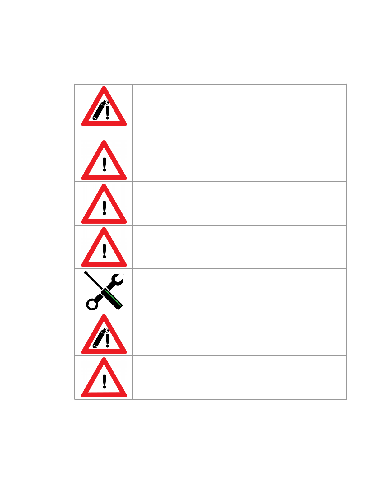
1 Warning - Read this first
Compressed air can be dangerous! Please familiarize yourself with the
forces under pressurized conditions. Respect the local guidelines and
regulations for working with pressurized equipment.
The pressure on the probe at 35 bar / 500 psi is around 40 Kilogram / 88
pounds force
! WARNING Mounting of this unit should be in De-Pressurized lines only !
Mount two safety chains, one to keep the probe in place, one for safety. Make
sure the hooks are completely closed. Make sure that the chains are strained as
these chains will keep the probe in position.
Use both safety eyes, to keep the force on the probe equal. Securing the probe
on one side will cause the probe to bend.
Use compression fittings with stainless steel ferrules. Please note that stainless
steel will permanently indent the probe and it cannot be used for any other
installation anymore.
Pressurize the system gently, 250 mbar per second. Fast pressurization may
result in shifting of the probe due to the pressure shock.
INSPECT the system after 30 minutes to see if the probe is still at the same
height. Systems with VIBRATIONS may be causing shifting of the probe.
Order numbers:
High pressure option for VPFlowScope probe
VPA.0001.092
Compression fitting with stainless steel ferrule
VPA.0001.003
Page 5

© 2018 Van Putten Instruments BV | AN-VP-SP35-UK | Revision:1800 | Date:23-02-2018
5
2 Installation step by step
The following cartoons show how to install the probe in a 35 bar system. in addition to the
compression fitting with stainless steel ferrules (rated well over 35 bar) we recommend to use two
safety chains, for redundancy.
Page 6

© 2018 Van Putten Instruments BV | AN-VP-SP35-UK | Revision:1800 | Date:23-02-2018
6 VPFlowScope 35 bar
Compression fitting instructions
NOTE: the following instructions apply to stainless steel ferrules only. For use with teflon ferrules,
there are no specific guidelines. This is why we do NOT recommend to use teflon ferrules in high
pressure systems.
Step 1:
Before tightening the nut, mark the 6 'o clock position
Step 2:
When fixing, use a wrench. Tighten the nut 1 ¼ turns. The mark on the nut turns 1-1/4
and will end at the 9 o’clock pos ition. Make sure the probe stays aligned during the
process.
If not, gently loosen the nut, align the probe and tighten it again. Rough turning of the
probe can cause scratches in the stainless steel and this might result in leakage.
Page 7

© 2018 Van Putten Instruments BV | AN-VP-SP35-UK | Revision:1800 | Date:23-02-2018
7
3 Specifications
Please always check the label of your product for the specifications.
Specifications are subject to change as we are continuously improving our products.
Please contact us to obtain the latest specification sheet.
Flow sensor
(minimum detection level and max flow rate shown)
Flow range
0.5...150 mn/sec
1.7…492 sfps
Accuracy
2% of reading under calibration condition
Recommended pipe diameter: 40mm | 1.5 inch and up
Reference conditions
0°C, 1013.25 mbar - DIN1343
32°F, 14.65 psi
Gas temperature
0...60°C
32...140°F
Gases
Compressed air, non aggressive gases and non combustible gases,
95% non condensing gases
Pressure sensor
Range
0...35 bar gauge
0…500 psi gauge
Accuracy
+/- 1.5% FSS (0...60°C)
+/- 1.5% FSS (32...140°F)
Temperature sensor
Range
0...60°C
32...140°F
Accuracy
+/- 1° (from 10 mn/sec and up) (At zero flow conditions, temperature
reading increases due to self-heating by the flow sensor)
Display
Technology
Liquid crystal
Back light
Blue with auto power save
Memory
2.000.000 point memory
Mechanical
Probe length
400 mm
15 inch
Probe diameter
12.7 mm
0.5 inch
Process connection
Compression fittings, 0.5 inch, NPT thread
Pressure rating
See product label. Only rated for high pressure when fixed with
stainless steel ferrules.
IP grade
IP52 when mated to display module
IP63 when mated to connector cap
Wetted materials
Alu, SS316, epoxy
Ambient temperature
0...60°C
32...140°F
Ambient humidity
10 - 95%. Avoid condensation at all times
Inputs and outputs
Analog
4..20mA or pulse, selectable via installation software
Serial IO
Modbus RTU
Supply
12..24 VDC +-10% CLASS 2 (UL)
Power consumption
150mA at 24VDC
Page 8

EASY INSI GHT I NTO ENERGY FLOWS
AN-VP-SP35-UK-1800
Date: 23 -02-201 8
Bui tenwaters loot 335
261 4 GS Del ft
The Nether lands
info@vpinstruments.com
www.vpinstruments.com
VPInstruments
 Loading...