

Page 1
1
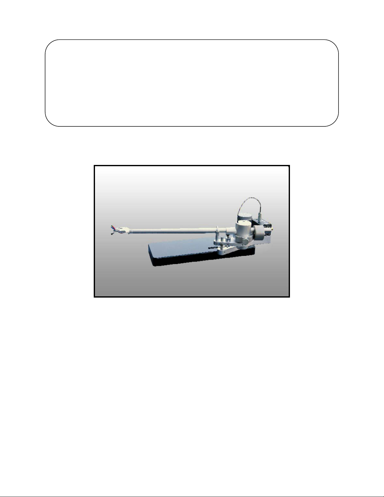
THE JMW-12.7 TONEARM
SETUP AND INSTRUCTION
MANUAL
VPI INDUSTRIES INC., 77 CLIFFWOOD AVE #3B, CLIFFWOOD N.J. 07721
PHONE: 732-583-6895, FAX: 732-946-8578
www.vpiindustries.com
Page 2

2
SETTING YOUR JMW 12.7 MEMORIAL TONE ARM
• You will see a number of th ings in pl astic ba gs:
• Allen wrenches
• Hex nuts, and washers (for cartridge mounting)
• Ar m mounting and alignment tool
• Shure stylus gauge
• Take all these items out and set them aside
A. CARTRIDGE MOUNTING:
• Remove the arm tube from the box (taking special care not to strain or damage, the delicate 4-
color wire and Lemo connector) and place it right side up o n t he foam pad.
FOR CARTRIDGES WITH THREADED MOUNTING HOLES:
• Use the screws supplied by the cartridge manufacturer to mount the cartridge. Any other
screws may not fit the thread pr operly and may even damage the threads and cart ridge. USE
ONE OF THE SUPPLIED WASHERS UNDER THE S CREW HEAD.
• For all cartridges with pass t hrough mounting holes use the hardware supplied with the arm.
Remember t o use the washers under the screw heads to pr event damage to the finish on the
JMW arm.
• In this step, the connecto r s will be att ached to the cartridge's terminals. Disregard the color of
the insulato r s on the cartridge clips.
THE COLOR COD E OF TH E WIRES IS AS FOLLOWS:
WHITE = left hot
RED = right hot
GREEN = right ground
BLUE = left ground
IF YOUR PHONO SECTION INVERTS P HASE, THE HOT BECOMES
THE GROUND COLOR
• The arm tube should be on its s ide on the foam pad when doing t his.
• Using tweezers or fine tipped pliers, grip the center of the red wire's connector (do not grip
the wire) and push it o nto the cartridge's right hot terminal pin. In the same way, connect
each of the remaining connectors to its respective cartridge terminal. Do not push the
connectors all the way on, as this could damage the cartr idge. Always back up the cart ridge
with yo ur finger when pushing on the c lips.
Page 3
3
• At the rear o f the arm base assembly is the connector block. Plug the Lemo connecto r into its
receptacle on top of the block. N otice that the connector can plug in only one way. Align the
red dot s on the arms plug with the red dot on the receptacle. Push gently do not force the
plug.
B. THE COUNTERWEIGHT:
• The JMW 12.7 tone arm comes with one large co unter weight installed on the rear shaft of the
tonearm. For most cart ridges you will only need this large weight. The counter weight is held
in position by a setscrew.
• The counterweight is used for setting the azimuth (lateral balance) of the cartridge and the
vertical tracking force.
• For now, po sition t he large count erweight t o give a minimum of tracking force, just enough
force to keep the cartridge on the alignment jig.
• In some rare cases it may be necessary to use two counterweights together. Contact your
dealer if a second counter weight is needed.
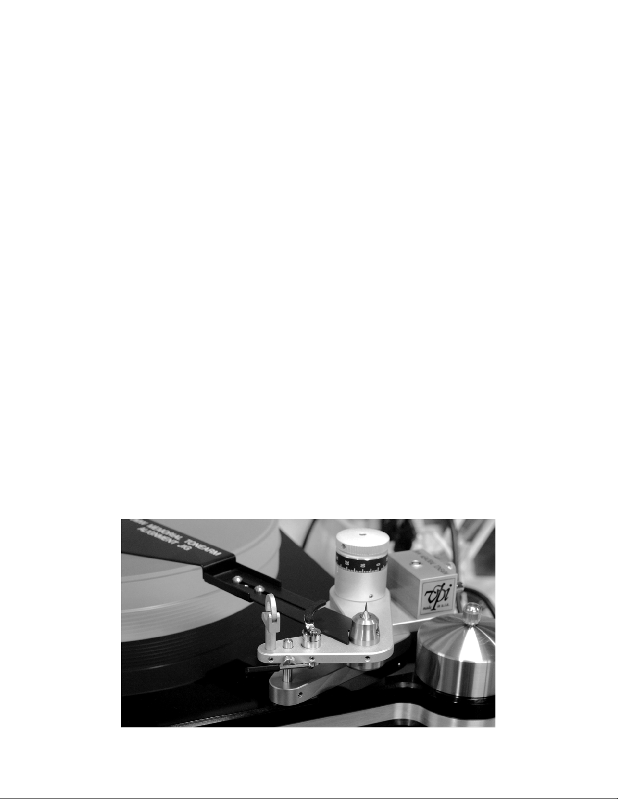
C. OVERHANG ADJUSTMENT & ALIGNMENT
• Th is adj ustme nt w ill yie ld t h e low e s t over a ll di s tor tion whe n pl a yin g a typi c a l 12" r e co rd. Do
not go crazy over this adjustment. You do not know if the stylus is aligned properly on the
cantilever. Yo u are also facing a constantly moving tar get when playing a record. The arm is
moving in 3-dimensions and will only approximate the accuracy you have built into your
alignment.
• Wit h t he a rm wa nd r emo ve d pla ce the Align ment Jig into po sit io n by slidi ng t he “V” cut o ut
against the male bearing and the hole over the spindle. If loose, adjust using the two scr ews.
Page 4

4
• Place the arm in its rest and apply enough tracking force to keep the stylus from moving.
Loosen the screws that hold the cartridge just enough so that t he cartridge can be moved back
and fo rt h.
• Carefully swing t he arm over the grid at the far end of the jig and place the stylus as close to
the do t in t he c en t e r of th e grid a s po s s ible . Us ing a ligh t e d magn ifie r will ma ke t his jo b ve ry
easy.
BE VERY CAREFUL NOT TO DAMAGE THE CARTRIDGE STYLUS:
• Move the cartridge so that the stylus rests on the dot. Now, viewing the cartridge from
abo ve, line it up so t hat its sides are symmetrically positioned bet ween the lines of the grid. If
the cartridge has parallel sides, these should be made parallel to the grid lines. Also make sure
that the cartridge is centered between the sets of lines. Follow figure 3 in the back of the
manual.
(JIG SHOWN IN WHITE FOR CLARITY)
• Double check the adjustments made above. The cartridge needs to be both centered and
"square" between the grid lines and have the stylus resting on the dot.
• The alignment gauge does no t h a ve a hole or di mple to h old the stylus. Wh ile the printe d dot
makes it harder t o ke ep the stylus in place, this method was cho sen to avoid the possibility of
damaging the stylus cantilever or t he diamond tip as the cartridge is positioned.
• Place the arm back in its rest.
• Without letting the cartridge move, tighten the screws holding the cart ridge to t he arm head.
Make it tight, but don't over do it and strip the threads or distort the cartridge body.
D. TRACKING FORCE:
• Moving the c ounter weight forward and back adjusts tracking force.
Page 5

5
• A Shure Stylus Force Gauge is supplied with your unit. Follow the gauge instruct ions and set
the tracking force to t he cartridge manufacturer’s highest recommendation plus 1/10 of a
gram more. We always recommend go ing t o the high side when it comes to tracking force.
High frequency vibrations can make a light t racking cartridge do more damage to t he gro oves
than running a cartr idge at a heavy setting.
E. AZIMUTH
• Next, the lateral balance or azimut h must be set. Because the phono cart ridge is offset, there
is an unbalancing for ce that t ilts t he arm to one side. For the cart ridge to pro perly tr ack the
record groove, the stylus must be ninety degrees to the record surface. Move the
counterweight so a slight tracking force is applied and the stylus just sits on the record
surface.
• By rotating the counter weight you can t ip the arm in either direct ion. Set the counterw eight
so t he cartridge sits as shown below. Do not move the counter weight front and back while
doing this, just side to side. If the arm is tipped to war ds t he left side rot at e the counterweight
so the botto m mass moves towards t he right. This will level t he arm.
Long thin rod
90 degrees
E. ANTI-SKATING:
• A piv o t e d ar m w ithout an o ffset head would not be subject to skating force. How ever, it will
also have no correction for tracking error and the resulting distortion is unacceptable. As
soon as the arm's head is offset to lower tracing distortion, skating force arises. Greater
offsets result in great er skat ing force. The 12” arm has a very small offset angle and therefore
a very low skat ing force to de al with.
Page 6

6
• After very careful listening tests we have determined that every tonearm we tried sounded
better with their mechanical anti-skating disabled and the tracking force very slightly
increased. All mechanical anti-skate devices add a negative sound t o the music because they
are made of parts that can vibrate. We solve the problem in a unique way:
• As me ntio n ed e a rlie r, t he arm wire applies the anti-skating force. The degree o f force applied
can be adjusted as explained below.
• To increase or decrease t he amount of anti-skating force applied, simply unplug the Lemo
connector and twist it in the direction you want the force applied.
• For example, to increase anti-skating force give the connector a counterclockwise twist,
unwinding the coiled wire. Likewise, to decrease t he force, give the connector a clockwise
twist. Remember, t he Lemo co nnect or can only be "adjusted" in increment s o f who le tur ns.
If it is not, its key will no t lin e up wit h t he gro ov e in the r eceptacle.
• We could go on discussing the pros and cons of how much anti-skate is correct, but t he sonic
answer is very simple. Adjust the wire as mentioned above until the tonearm drifts outward
when set to neutr al balance. When you push the neutral balance floating tonearm towards
the center of the reco rd, it should push back out towards the rim of the record. Very little
force is needed to do t his, and the wire acts like a spring to supply this force.
• If you try adjusting the anti-skate with a groove less record or a test record you will
ruin the twist in the wire and void your warrantee
• Double check the horizontal balance, lateral balance, and tracking force and adjust as needed.
Increase the tracking force by 1/10 of a gram above the cartridge manufacturers highest
recommended force.
G. ARM HEIGHT:
NOTE: THE TWO THUMBSCREWS MUST BE RELEASED WHEN MOVING THE
VTA KNOB. THE THUMBSCREWS S H O U LD BE TIGHTENED WHEN LIS TEN ING .
Unlike many t o ne a rms, t he JMW's height is bo t h eas y and r epe at able t o var y. The kno b next t o
the bearing housing bears a scale numbered from zero to ninety-nine. Belo w the kn o b t he r e is a n
index mark engrave d on t he fro nt of t he supp ort pillar. Rot ating the knob clockw ise lowers t he
arm and rotating it counterclockwise raises it.
Set t he arm height as follows:
• Place a recor d o n the platt er surface. Lower t he arm onto t he record and make the arm tube
parallel to the record surface by rotat ing the arm-height knob a s ne eded.
• This is a good initial setting. You may wish to vary it depending on the cartridge you are
using and or the part icular record being played. The knob's scale makes it easy to retur n to a
previous sett ing by making a not e of t he number abo ve the index mar k and the number o f
complete turns taken.
Page 7

7
• The old wisdom, which had the arm tube parallel to the reco rd surface, assumed not only that
all cartridges had the same internal geometry and stylus rake angle but also that all records
were cut with the same equipment set t he same way. The idea was that everything would line
up properly with the arm parallel to the record. This is not true and the VTA should be
adjusted for best sound in your system.
• Rule of thumb: Raising VTA lowers bass and increases treble. Lowering VTA increases
bass and decreases treble.
H. CONNECTING TO THE PREAMPLIFIER/AMPLIFIER
• ONLY USE INTERCONNECTS THAT ARE SHIELDED AND PROPERLY GROUNDED. NON-
SHIELDED INTERCONNECTS CAN HUM AND PICK UP RF .
• The connecto r block at t he rear of the arm base has, in addition to the Lemo receptacles two
phono recept acles and a ground connector.
• Plug one end of the output cable into the phono jacks. The jack with the red ring is the right
channel and the jack with the black or w hit e r ing is the left.
• Plug the other end of the ca ble into the tur ntable inputs on your pre-preamplifie r, preamplifier,
or integrated amplifier as appropriate.
The ground connection is available to eliminate hum if necessary. If hum is present, first connect
a gro und lead from the co nnecto r block t o t he preamplifier or amplifier t o which the output cable
is connected. If this does not eliminate t he hum, run a ground wire from the turntable chassis to
the connector block as well. The block's connector will accept bare wires, spade lugs, or ring
tongue connectors.
I. D AMPING THE ARM
• The JMW-12.7 has v is c ous dampi n g prov is ion a ro und its ma le b e a ring point. Lif t o ff the a rm
tube and fill the cup roughly ¾ full with the damping fluid provided.
• Pla c e t h e ar m ba c k o n t h e b ea r ing a nd lift it s ligh t ly t o s e e if th e dampi ng flui d lift s up w it h it
in a thin line. That means you ar e making contact with the fluid and you are damped.
J. FINE TRACKING FORCE ADJUSTMENT
• At the rear of the counterweight stem there is an adjustment screw that allows fine
adjustment of the tracking for ce. This screw may feel tight when first engaging it but it will
turn with the supplied 3/16” Allen wrench.
• Use this screw for very fine adjustment of the tracking force.
Page 8

 Loading...