

Page 1
VPI
VIDEO
PRODUCTS
INCORPORATED
1275 Danner Drive
Tel: 1-800-626-7801
www.vpi.us
Aurora,Ohio 44202
Fax: 330-562-1999
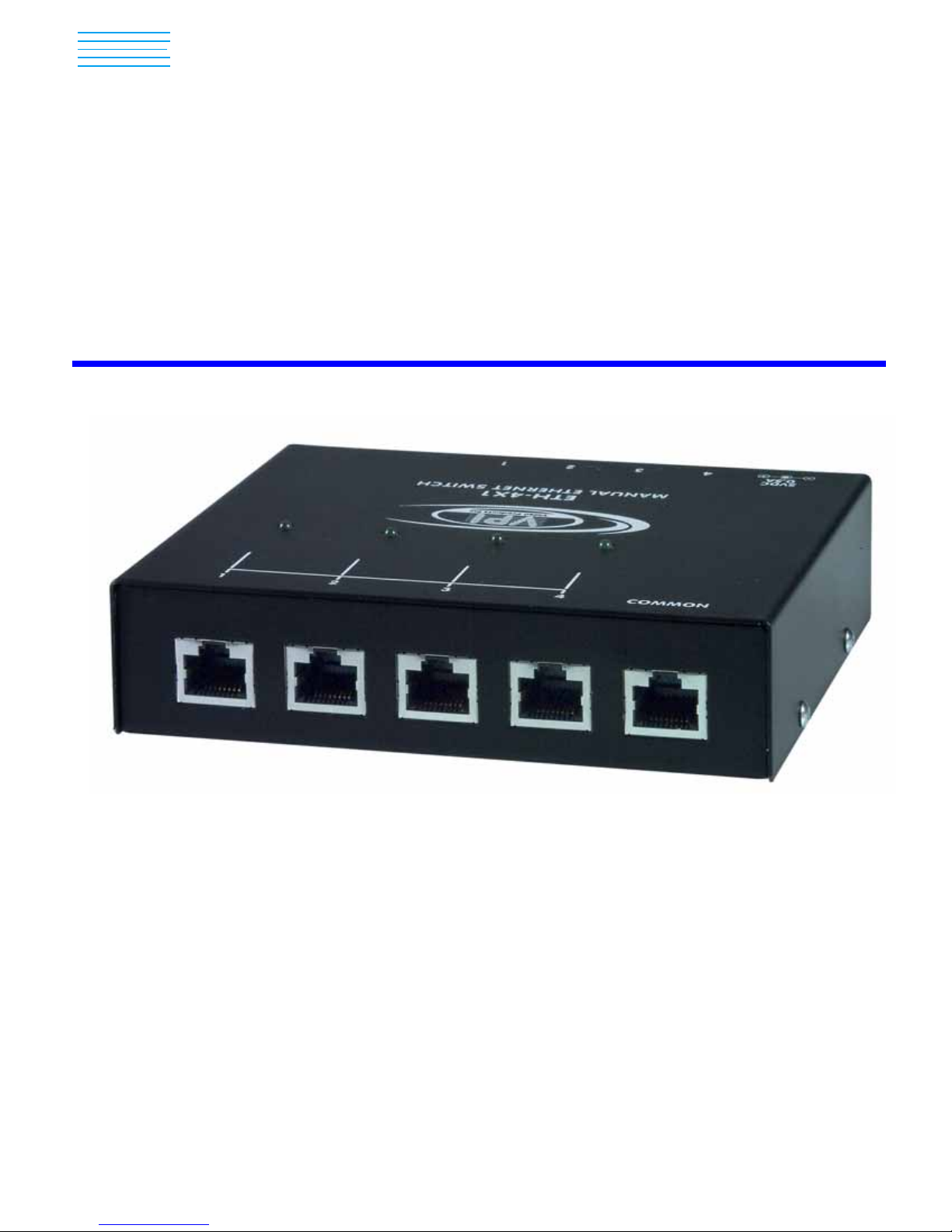
ETH-4X1-G / 2X1-G / 2X1
Manual Ethernet Switch
Installation and Operation Manual
MAN048 Rev Date 6/18/2007
Page 2

COPYRIGHT
Copyright © 2002, 2007 by Video Products Incorporated. All rights reserved. No part of this publication may
be reproduced, stored in a retrieval system, or transmitted, in any form or by any means, electronic,
mechanical, photocopying, recording, or otherwise, without the prior written consent of Video Products
Incorporated, 1275 Danner Drive, Aurora, Ohio 44202
CHANGES
The material in this manual is for information only and is subject to change without notice. Video Products
Incorporated reserves the right to make changes in the product design without reservation and without
notification to its users.
i
Page 3

TABLE OF CONTENTS
Introduction...................................................................................................................................... 1
Glossary....................................................................................................................................... 1
Supported Device Types.............................................................................................................. 1
Supported Operating Systems.....................................................................................................1
Application Examples...................................................................................................................... 2
Materials.......................................................................................................................................... 3
Preparation for Installation............................................................................................................... 3
Features and Functions................................................................................................................... 4
Installation........................................................................................................................................ 5
Connect the Cables ..................................................................................................................... 5
Plug-in and Boot Up..................................................................................................................... 6
RS232 Control.............................................................................................................................. 7
Remote Connection .................................................................................................................. 7
Command Protocol ................................................................................................................... 7
NTI Switch Control Program For Windows 9X, NT, 2000 AND XP............................................. 8
SerTest- RS232 Interface Test Program ..................................................................................... 8
Main Options............................................................................................................................. 8
Switch Operations..................................................................................................................... 8
Setup Options ........................................................................................................................... 9
Technical Specifications..................................................................................................................9
Interconnection Cable Wiring Method- Straight Thru................................................................... 9
Interconnection Cable Wiring Method- Crossover..................................................................... 10
Troubleshooting............................................................................................................................. 10
Warranty Information.....................................................................................................................10
ii
Page 4

INTRODUCTION
The NTI ETH-4X1-GManual Ethernet Switch was designed to enable the connection between a common DEVICE or NETWORK
and one of up to four DEVICEs or NETWORKs using standard Ethernet cable. The ETH-4x1-G is a switch that provides reliable
physical signal separation between connected devices while supporting 10Base-T, 100Base-T, and 1000Base-T connections.
Push buttons on the switch provide easy user control over the ETH-4X1-G to make a single connection active between two
Ethernet-based devices at a time.
Available Options
• Manual Ethernet Switch with 2 user selectable connection ports rather than 4 (ETH-2X1-G)
• 2-Port Manual Ethernet Switch with support for only 10Base-T and 100Base-T connections.(ETH-2X1)
• RS232 control to change connections in the Ethernet switch via a serial stream (ETH-4X1-RS-G or ETH-2X1-RS-G)
Glossary
CPU- Computer for user access
DEVICE- CPU or other data entry/acquisition equipment
NETWORK- Local Area Network (LAN)* , File server, DSL internet connection
MDI- Media Dependent Interface
MDIX- Media Dependent Interface Crossover
COMMON- A DEVICE or NETWORK that is to be commonly connected to the selected NETWORK or DEVICE
(up to 4) through the ETH-4X1-G Manual Ethernet Switch
SELECTABLE- Any NETWORKs or DEVICEs (up to 4) that will be plugged into the user selectable ports
(1-4) and connected to the COMMON through the ETH-4X1-G Manual Ethernet Switch
*Note: The ETH-4X1-G Manual Ethernet Switch cannot differentiate between LANs and cable/DSL modems. For the
purposes of this manual they will be considered to be identical.
Supported Device Types
• Routers
• HUBS
• ETHERNET Switches (Managed / UN-managed)
• PC’s
• Network Appliances
• IEEE 802.3 Supported Devices
Supported Operating Systems
Any IEEE 802.3 compliant operating system
1
Page 5

APPLICATION EXAMPLES
L
S
D
U
P
C
COMMON
5VDC
.5A
+
-
R
E
V
R
E
S
VPI
Video Products Inc
ETH- 4X1-G
MANUAL ETHER NET SWITCH
4321
U
P
M
E
M
D
O
1234
R
E
T
U
O
R
C
U
P
C
U
P
C
CAT5e/CAT6 UTP cable
RJ45 male-male
See "Note" on page 3
N
A
L
e
M
m
e
d
o
l
b
a
C
U
P
C
5VDC
.5A
+
-
U
P
C
U
P
C
COMMON
VPI
Video Products Inc
ETH-4X1- G
MANUAL ETHER NET SWITCH
4321
U
P
C
COMMON
U
P
C
1234
U
P
C
1234
U
P
C
CAT5e/CAT6 UTP cable
RJ45 male-male
See "Note" on page 3
U
P
C
CAT5e/CAT6 UTP cable
RJ45 male-male
See "Note" on page 3
MANUAL ETHER NET SWITCH
5VDC
.5A
4321
+
-
VPI
Video Products Inc
ETH- 4X1-G
2
Page 6

MATERIALS
Materials Supplied with this kit:
• NTI ETH-4X1-G / ETH-2X1-G Manual Ethernet Switch
• 120 VAC at 60 Hz 5VDC/.5A AC Adapter
• CD with this manual in pdf format and RS232 control programs (ETH-4X1-RS-G / ETH-2X1-RS-G only)
Materials Not Supplied, BUT REQUIRED:
• Ethernet Cables- Cat5e/Cat6 UTP cable with male-male connectors, either wired straight-thru or crossover, depending upon
the connected component. See note below.
Note: A crossover cable may be required if any connected components (NETWORK or DEVICE) do not support Auto
MDI/MDIX cable selection. Once a component is properly connected and powered ON, a link LED should illuminate to
indicate communication with another component. If it does not illuminate, a crossover cable may be required. See
pages 9 and 10 for cable pinouts.
PREPARATION FOR INSTALLATION
• A location should be chosen for the ETH-4X1-G such that the Ethernet cable from each supported device will reach it.
• The Ethernet cables must be run to the locations where the ETH-4X1-G switch, COMMON, and the SELECTABLE(s) will be
mounted. Be careful to route the cables away from any sources of magnetic fields or electrical interference that might reduce
the quality of the signal (i.e. AC motors, welding equipment, etc.).
• A 120V electrical outlet must be available close enough to the mounting location of the ETH-4X1-G to plug the AC adapter
into.
• All cables should be installed in such a way that they do not cause stress on their connections to the equipment. Exten ded
lengths of cable hanging from a connection may interfere with the quality of that connec tion. Secure cables as needed to
minimize this.
3
Page 7

Front View of ETH-4X1-RS-G
COMMON
12 34
VPI
Video Products Inc
R
ETH-4X1-RS-G
MANUAL ETHERNET SWITCH
-
5VDC
.5A
+
432 1
RS232
1
2
3
4
Rear View of ETH-4X1-RS-G
RS232
Video Products Inc
R
VPI
NETWORK
5
43 2 1
MANUAL ETHERNET SWITCH
ETH-4X1-RS-G
4321
6
-
+
.5A
5VDC
COMMON
FEA TURES AND FUNCTIONS
1. 5VDC .5A- male connection jack for the AC adapter
2. Port Select Switches- (1-4)- for manual control of "COMMON"* and user selectable ports (1-4)
Note: ETH-2x1-G Switch has only 1 Port Select switch that toggles between ports when pressed.
3. RS232- 9 pin DIN male (optional)- for computer control of "COMMON"* and user selectable ports (1-4) (only on models
with RS232 option)
4. Status LEDs- for visual indication of switch connection between the "COMMON"* and the user selectable ports (1-4)
5. User Selectable Ports (1-4)- RJ45 female- for connection of SELECTABLEs*
Note: ETH-2x1-G Switch has only 2 user selectable ports.
6. COMMON port- RJ45 female- for connection of COMMON*
*See Glossary (page 1) for explanation of “COMMON” and “SELECTABLE”.
4
Page 8

INSTALLATION
Connect the Cables
1. Position the ETH-4X1-G such that the Ethernet cable from the COMMON , the AC adapter power cable, and the
Ethernet cables from the SELECTABLEs can reach the ETH-4X1-G.
2. Connect one end of an Ethernet cable to the COMMON (See Fig.1.) Connect the other end of that
cable to the "COMMON" port on the ETH-4X1-G.
3. Connect another Ethernet cable between each SELECTABLE and the user selectable ports (1-4) on the
ETH-4X1-G. (See Figs.1 and 2.)
Rear View of CPU
(DEVICE)
RJ45 Female
RJ45 Male
Rear View of ETH-4X1-G
R
R
NETWORK
RJ45 Male
Ethernet Cable
See note under “Materials” on page 3
-
432 1
+
.5A
5VDC
MANUAL ETHERNET SWITCH
ETH-4X1-G
Video Products Inc
VPI
COMMON
4321
RJ45 Ethern et Cab le
to COMMON device
(NETWORK)
RJ45 Female
Figure 1- Connect DEVICE to switch
RJ45 Female
See note under “Materials” on page 3
Figure 2- Connect NETWORK to switch
Cable Modem
(NETW O RK)
RJ45 Male
Ethernet Cable
Rear View of ETH-4X1-G
R
RJ45 Male
5
-
+
432 1
.5A
5VDC
MANUAL ET HERNET SWITCH
ETH-4X1-G
Video Pr oducts I nc
VPI
R
NETWORK
COMMON
4321
RJ45 Ethernet Cable
to COMMON device
(DEVICE)
RJ45 Female
Page 9
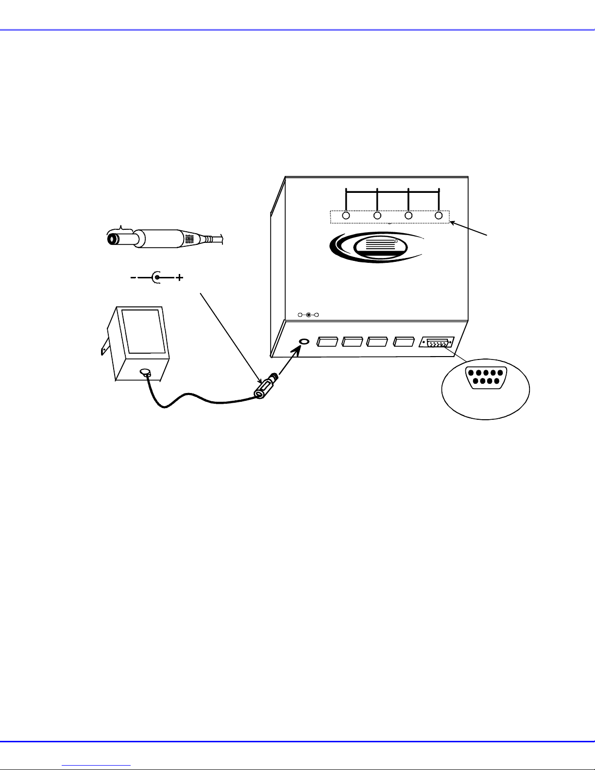
Plug-in and Boot Up
1. Connect the AC adapter power connector to the 5VDC port on the ETH-4X1-G. Make sure the power connector is
properly inserted. (See Fig. 3.)
2. Plug the AC adapter into a power outlet. The status LED for SELECTABLE port 1 will illuminate indicating a proper
power connection has been made.
Note: An illuminated Status LED also indicates a connection between the "COMMON" port and the associated user
selectable port.
Barrel
Power Connector
5VDC @ .5A OUTPUT
(Outside
barrel)
2.1 mm x 5.5 mm Female
(Inside
barrel)
5 VDC
Adapter
ADAPTER
Front View of ETH-4X1-RS-G
4
COMMON
NETWORK
R
R
VPI
Video Products Inc
ETH-4X1-RS-G
MANUAL ETHERNET SWITCH
5VDC
.5A
+
-
4321
12 3
RS232
DB9 Male
RS232 Connector
Status LEDs
Figure 3- Connect the AC adapter
3. Power up the COMMON and SELECTABLE device(s). The COMMON device should react as if it were directly
connected to the SELECTABLE device plugged into user selectable port 1.
6
Page 10

RS232 Control
RS232 (optional) enables the ETH-4X1-RS-G to be remotely controlled via RS232. T o control the ETH-4X1-RS-G via RS232 the
user has three options:
• write a program that runs on a PC using the Command Protocol (below)
• use the NTI Switch Control Program (page 8) provided on the CD
• use the SerTest program (page 8) provided on the CD
Remote Connection
The RS232 Interface is designed to control the switch via serial (RS232) connection from any host computer or other controller
with an RS232 communications port. To use the RS232 port , connect a crossed female serial cable from a CPU serial port to
the DB9 pin male RS232 port on the ETH-4X1-RS-G. Connections are as follows:
RS232 Connector (DB9 Male)
Pins at
ETH-4X1-RS-G
2 RxD 3
3 TxD 2
5 GND 5
RS232 program setup parameters:
• 9600 baud
• 8 bit data
• 1 stop bit
• no parity
• no flow control
Signal Pins at
CPU
"RS232" Connector
4
1
6
3
2
8
7
5
9
Mating Face of DB9 Male
Command Protocol
CPU controller commands supported by the unit are defined below. Commands may be sent using any RS232 commu nication
program (i.e. Windows HyperTerminal). All commands should be terminated with a <CR> (carriage return). When a command is
sent, the entire string is echoed back along with a response from the addressed unit as shown in the command definition s table
below. All characters in the command string should be upper case, and all numbers below 10 should have a leading 0 (ex: 1 =
01). As command strings are sent, the inner character delay cannot exceed 500 milliseconds.
The following commands are supported.
LEGEND
SW: SWITCH UNIT ADDRESS- this is 01 and cannot be changed)
OP: OUTPUT (COMMON) PORT -this is 01 and cannot be changed
IP: INPUT NETWORK PORT (01-MAXINPUTS) (MAXINPUTS = 02 or 04)
<CR>: CARRIAGE RETURN (Hex 0x0D)
Command String Good Response Description
CS SW,IP,OP *<CR> Connect COMMON Port To Input/SELECTABLE Port
RO SW,OP *<CR>IP<CR> Read Connection For Output/COMMON Port
RU SW *<CR>IP,OP<CR> Read Unit Size
RV SW,00 *<CR>string\0<CR> Read NTI Version String (Short Version)
RV SW,01 *<CR>string<CR> Read NTI Version String (Long Version)
If the first field is not a known command (as listed above) or SW field is different from the serial address programmed in the switch
memory (01), the command will be ignored. If the SW field corresponds to the unit address, but the syntax is wrong after this field,
the switch will answer with a bad response ?<CR>.
ALL NUMBERS MUST BE TWO DIGITS
7
Page 11

NTI Switch Control Program For Windows 9X, NT, 2000 AND XP
The NTI Switch Control Program is an easy and powerful graphical program that controls NTI switches through an RS232
interface. The NTI Switch Control Program is included on the manual CD packaged with the ETH-4X1-RS-G. The NTI Switch
Control Program can be downloaded to your computer by clicking on the link "Dow nload NTI Switch Control Program" found o n
the web page that appears when you insert the instruction manual CD into your CD ROM drive.
To install the NTI Switch Control Program after downloading it to your computer from the manual CD:
1. Locate the Setup.exe in the directory the program was downloaded to and double-click on it
2. Follow the installation instructions on the screen
The NTI Switch Control Program performs best on monitors set to a screen resolution of at least 800 X 600. Instruction for using
the NTI Switch Control Program is available by opening "MSCP Help" in t he "NTI" program group once the program has been
installed and is open on the screen.
To open "MSCP Help" from the Windows desktop:
1. Click on START
2. Click on PROGRAMS
3. Click on NTI
4. Click on MSCP Help
SerTest- RS232 Interface Test Program
This software allows a user to test the functions of an NTI server switch, matrix switch, Ethernet switch, or Multi-user/Multiplatform switch RS232 interface. The program SERTEST along with the NTI Switch Control Program (above) is installed from
the CD packaged with this switch. SERTEST generates a main menu with the 4 selectio ns described below:
Main Options
• Switch Operations
• Ethernet Operations
• Setup Options
• About SerTest
- send commands to the ETH-4X1-RS-G
- set Ethernet connection variables (not applicable to this switch)
- set COM port, baud rate, and unit address
- display the program version
Switch Operations
Key Selection Description
1) Connect Video Output/User to an Input/CPU - connect an output (COMMON) to an input(SELECTABLE)
2) Connect All Video Outputs/Users to an Input/CPU - connect all outputs to an input
3) Connect Audio Output/User to an Input/CPU - connect an output to an input (audio ports only)
4) Connect All Audio Outputs/Users to an Input - connect all outputs to an input (audio ports only)
5) Change Mute Status for Audio Output/User (not
applicable to this unit)
6) Change Volume for Audio Output/User (not
applicable to this unit)
7) Read Connection for Video Output/User -read the connection of a specific video output (COMMON (01))
8) Read Connection for Audio Output/User -read the connection of a specific audio output
9) Read Mute and Volume for Audio Output/User - read the volume and the mute status of the specified audio output
a) Save I/O Connections into Unit Memory -save the connections into switch memory bank
b) Restore I/O Connections from Unit Memory -restore the connections from switch memory bank
c) Change All Units Baud Rate (9600/COM1:) -change RS-232 Baud rate of all switches
d) Reset Unit - send a reset command to the switch
e) Reset All Units - send an internal reset command to all switches
f) Read Unit Size - read the switch size (number of inputs and outputs)
g) Read Unit Version/Revision String -read a string containing the switch version, type, and size
h) Save All Units I/O Connections into Units Memory -save the connections into switch memory bank, command for all
i) Restore All Units I/O Connections from Units
Memory
Selections in the "Key" column that are gray are not applicable to this product.
- mute or un-mute the Audio port output
- change Audio port output volume
-the current baud rate and serial port are displayed in parentheses
- the current unit address is displayed in parentheses
switches
-restore the connections from switch memory bank, command for all
switches
8
Page 12

Setup Options
Key Selection Description
1) select Com port current:
(COM1:)
2) select Baud rate current:
(9600)
3) set unit Address current:
(1)
For any selection that requires user input, the user is prompted. When commands are sent to the switch, the command string and
switch responses are echoed to the screen. All commands generated by the program are formatted according to the information
provided in sections above. If any transmission problems are detected, an error message is displayed.
Press <Esc> or <Enter> to back out to the main menu and press again to exit.
- select PC serial port
- the current PC serial port is displayed in parentheses
- select PC serial port baud rate
- the current baud rate is displayed in parentheses
- select the unit address
- the current address is displayed in parentheses
TECHNICAL SPECIFICATIONS
Interconnect Cable
Power 120VAC @ 60Hz 5VDC / .5A AC Adapter (provided)
ETH-4X1-G current draw < 0.2A @ 5VDC
Dimensions WxDxH (in.) 5.25 x 4.375 x 1.375
CAT5e/CAT6 UTP Male-Male cables (see note under
“Materials” on page 3)
Interconnection Cable Wiring Method- Straight Thru
In order to make a direct connection between two devices that support Auto MDI/MDIX, a cable wired straight-thru can be used.
The cable is made with CAT5e/CAT6 UTP cable terminated with male RJ45 connectors and wired according to the EIA /TIA 568A
industry standard. Both ends are wired is as per the table and the drawing below.
Pin # Wire Color
1 White/Orange
2 Orange
3 White/Green
4 Blue
5 White/Blue
6 Green
7 White/Brown
8 Brown
9
Page 13

Interconnection Cable Wiring Method- Crossover
In order to make a direct connection between two devices that do not support Auto MDI/MDIX, a crossover cable must be used
either at the SELECTABLE port end or at the COMMON port. The cable is made with CAT5 cable terminated with male RJ45
connectors and wired according to the EIA /TIA 568A industry standard. The cable is wired according to the chart below.
Pin assignment at
Standard End
1 White/Orange 3
2 Orange 6
3 White/Green 1
4 Blue 4
5 White/Blue 5
6 Green 2
7 White/Brown 7
8 Brown 8
Wire Color Pin assignment at
Crossed End
Standard
End
Crossed
End
Crossover Cable
TROUBLESHOOTING
Each and every piece of every product produced by Video Products Inc is 100% tested to exacting specificatio ns. We make
every effort to insure trouble-free installation and operation of our products. If problems are encou ntered while installing this
product, please look over the troubleshooting chart below. If an answer is not found in the chart, check the FAQs (Frequently
Asked Questions) at our website at http://www.vpi.us
562-2622 (worldwide). We will be happy to assist in any way we can.
or contact VPI directly for help at 800-626-7801 in US & Canada or 330-
Problem Cause Solution
Status LEDs do not illuminate
NETWORKS(s) will not
communicate with DEVICE(s)
(no link light(s) ON)
• Power supply is not connected
or plugged-in.
• Poor Connection
• Wrong Ethernet cable
• Make sure outlet is live and AC adapter is
plugged in. Also make sure power jack is
fully connected to the switch.
• Make sure all Ethernet cables are inserted
completely, snapping into RJ45 sockets
• Cable must be CAT5e/6 - see note under
“Materials” on page 3
WARRANTY INFORMATION
The warranty period on this product (parts and labor) is one (1) year from the date of purchase. Please contact Video Products
Incorporated at
number is required for all repairs/returns.
MODEL : ETH-4X1-G
(800) 626-7801 or (330) 562-2622 for information regarding repairs and/or returns. A return authorization
ETH-2X1-G
ETH-4X1-RS-G
ETH-2X1-RS-G
ETH-2X1
Man048 Revised 6/18/2007
10
 Loading...