

VPEB Dinamo, OC32/NG, RM-C/1+, TM44, OC32 User Manual

Manual DINAMO Plug & Play Control your miniature world
Page 32 of 32 Version 1.2 – Dec 21st, 2017 2017 Leon van Perlo
(This page is intentionally left blank)
Author: Leon J.A. van Perlo
Version: 1.2
Date: December 21st, 2017
DINAMO Plug & Play
Manual
VPEB
Van Perlo Elektronica
& Besturingstechniek
VPEB
Van Perlo Elektronica
& Besturingstechniek
Smart electronics for your miniature world
Manual DINAMO Plug & Play Control your miniature world
Page 2 of 32 Version 1.2 – Dec 21st, 2017 2017 Leon van Perlo
Release Management
This manual applies to the kit consisting of:
Module:
•
RM-C/1+ Rev00/01
•
TM44 Rev01
•
OC32/NG Rev10
If you have an RM-U P&P and/or an OC32 (not /NG version) please refer to version 1.1 of
this manual for the hardware description of the respective parts. You can however use
all firmware and software described in this manual version 1.2.
Firmware:
•
RM-C Firmware 1.30A
•
TM44 Firmware 1.20
•
OC32 Firmware 3.01
Software:
•
DinamoConfig 1.30A
•
OC32Config 3.01
Preface
The Dinamo Control System is a versatile solution to control analogue trains, digital trains,
digital cars and all accessories on your miniature world in scale 00 (1:6 7.2) to scale Z
(1:220) including all intermediate scales. Application of Dinamo with larger scales is
possible, however some limitations may apply.
The versatility of Dinamo may confuse less electronic mind users. For th is reason VPEB
released Plug&Play. In this version, the number of different types of modu les and the
possible choices are reduced in favor of clarity and simplicity. Dinamo P&P is in contrast to
Dinamo “Classic” not suited for application with larger scales than H0/0 0 (and so primarily
intended for scales from 00 to Z).
This manual describes strictly the Dinamo Plug&Play concept and its application for the
operation of trains for the novice user as simply as possible. Dinamo P&P can be enhanced
with additional modules from the Dinamo “Classic” range e.g. the UCCI/E -s for controlling of
digital cars. There are also other choices not described in this manua l that are possible,
however these are outside the scope of this manual. The user is adv ised to refer to the
individual manuals for the other modules for in-depth details.
Even though the application of Dinamo P&P has been significant ly simplified compared to the
"Classic" version, before you apply this to your final model layout it is important to
understand the principles and to understand how the software and D inamo system
cooperate with each other. Creating a temporary simple test layout has proven to be very
effective way to learn and most of the items can be reused afterwa rds in your final layout.
2017 This document, or any information contained herein, may not be copied or distributed, in whole
or in parts, in whatever form, without the explicit written approval of the original author. The making of
copies and prints by users of the Dinamo system and/or Dinamo modules for their own use is allowed.
Control your miniature world Manual DINAMO Plug & Play
2017 Leon van Perlo Version 1.2 – Dec 21st, 2017 Page 31 of 32
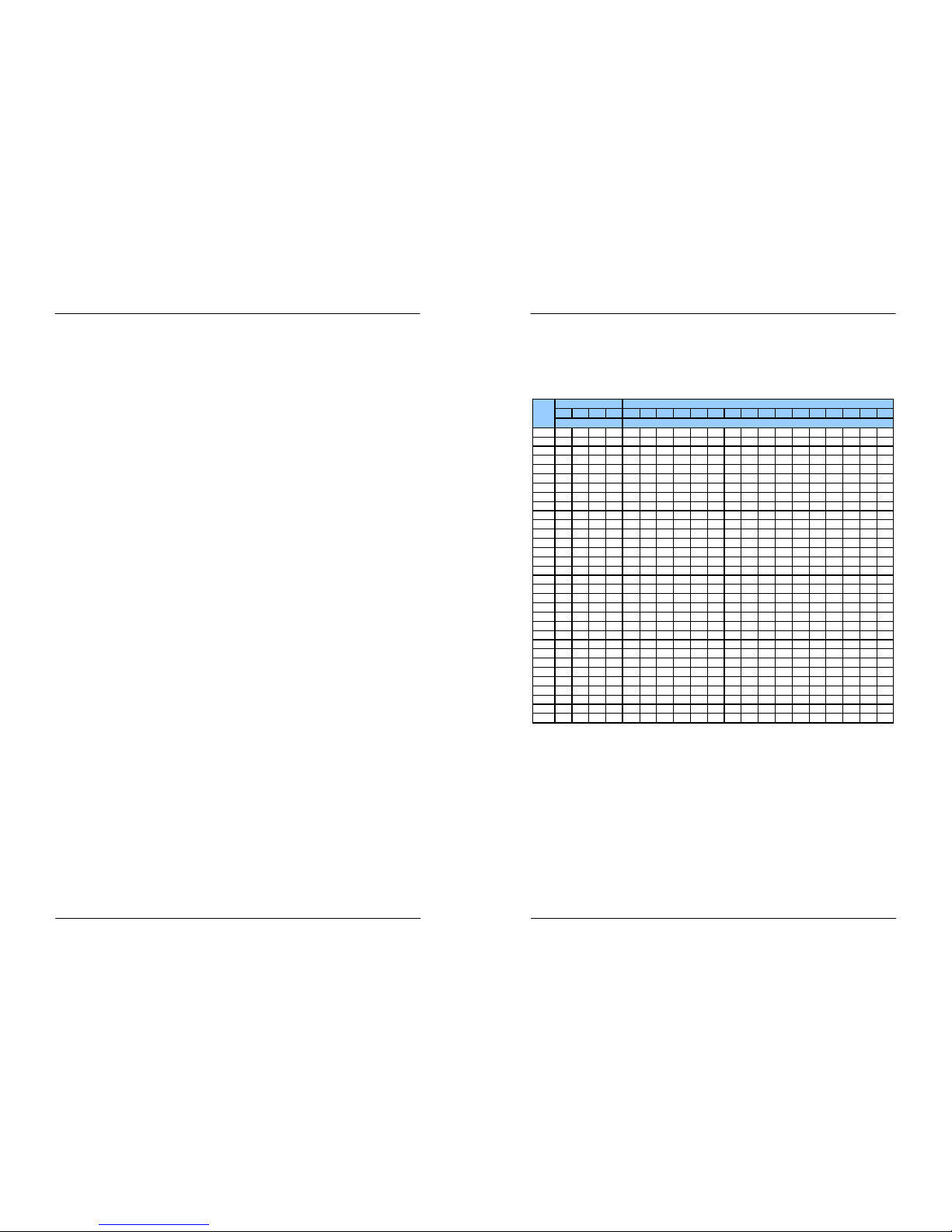
Appendix A: TM44 Address Table
This table applies if your control software uses linear addressing a nd adds an offset +1 to
block and feedback addresses.
Note that the TM44 numbering is kept as in this manual, starting fro m 0.0
TM440123
0B0
0B1
0B2
0B3
1B0
1B1
1B2
1B3
2B0
2B1
2B2
2B3
3B0
3B1
3B2
3B3
0.0123412345678910111213141516
0.1567865666768697071727374757677787980
1.0 9 10 11 12 129 130 131 132 133 134 135 136 137 138 139 140 141 142 143 144
1.1 13 14 15 16 193 194 195 196 197 198 199 200 201 202 203 204 205 206 207 208
2.017181920
257
258
259
260
261
262
263
264
265
266
267
268
269
270
271
272
2.121222324
321
322
323
324
325
326
327
328
329
330
331
332
333
334
335
336
3.025262728
385
386
387
388
389
390
391
392
393
394
395
396
397
398
399
400
3.129303132
449
450
451
452
453
454
455
456
457
458
459
460
461
462
463
464
4.033343536
513
514
515
516
517
518
519
520
521
522
523
524
525
526
527
528
4.137383940
577
578
579
580
581
582
583
584
585
586
587
588
589
590
591
592
5.0 41 42 43 44 641 642 643 644 645 646 647 648 649 650 651 652 653 654 655 656
5.145464748
705
706
707
708
709
710
711
712
713
714
715
716
717
718
719
720
6.049505152
769
770
771
772
773
774
775
776
777
778
779
780
781
782
783
784
6.153545556
833
834
835
836
837
838
839
840
841
842
843
844
845
846
847
848
7.057585960
897
898
899
900
901
902
903
904
905
906
907
908
909
910
911
912
7.161626364
961
962
963
964
965
966
967
968
969
970
971
972
973
974
975
976
8.065666768
1025
1026
1027
1028
1029
1030
1031
1032
1033
1034
1035
1036
1037
1038
1039
1040
8.169707172
1089
1090
1091
1092
1093
1094
1095
1096
1097
1098
1099
1100
1101
1102
1103
1104
9.0 73 74 75 76 1153 1154 1155 1156 1157 1158 1159 1160 1161 1162 1163 1164 1165 1166 1167 1 168
9.177787980
1217
1218
1219
1220
1221
1222
1223
1224
1225
1226
1227
1228
1229
1230
1231
1232
10.081828384
1281
1282
1283
1284
1285
1286
1287
1288
1289
1290
1291
1292
1293
1294
1295
1296
10.185868788
1345
1346
1347
1348
1349
1350
1351
1352
1353
1354
1355
1356
1357
1358
1359
1360
11.089909192
1409
1410
1411
1412
1413
1414
1415
1416
1417
1418
1419
1420
1421
1422
1423
1424
11.193949596
1473
1474
1475
1476
1477
1478
1479
1480
1481
1482
1483
1484
1485
1486
1487
1488
12.0979899100
1537
1538
1539
1540
1541
1542
1543
1544
1545
1546
1547
1548
1549
1550
1551
1552
12.1 101 102 103 104 1 601 1602 1603 1604 1605 1606 1607 1608 1609 1 610 1611 1612 1613 1614 1615 1616
13.0 105 106 107 108 1 665 1666 1667 1668 1669 1670 1671 1672 1673 1 674 1675 1676 1677 1678 1679 1680
13.1
109
110
111
112
1729
1730
1731
1732
1733
1734
1735
1736
1737
1738
1739
1740
1741
1742
1743
1744
14.0
113
114
115
116
1793
1794
1795
1796
1797
1798
1799
1800
1801
1802
1803
1804
1805
1806
1807
1808
14.1
117
118
119
120
1857
1858
1859
1860
1861
1862
1863
1864
1865
1866
1867
1868
1869
1870
1871
1872
15.0
121
122
123
124
1921
1922
1923
1924
1925
1926
1927
1928
1929
1930
1931
1932
1933
1934
1935
1936
15.1
125
126
127
128
1985
1986
1987
1988
1989
1990
1991
1992
1993
1994
1995
1996
1997
1998
1999
2000
Block Address
Block
Feedback Address
Section
Table 4: TM44 block –and section numbers

Manual DINAMO Plug & Play Control your miniature world
Page 30 of 32 Version 1.2 – Dec 21st, 2017 2017 Leon van Perlo
7.4 Delivering Track-power to Turnouts via Relays
In paragraph 7.3 we explained that in some cases it is necessary to power the track s on
turnout groups separately. If you don’t want to do that with an ad ditional block-output or if
you cannot do that because your software does not support it, you can solve this with a
relay, controlled from an OC32 output. Since the track, the relay pow ers, is only occupied
while the train passes to or from the adjacent blocks there is funct ionally no disadvantage,
except that it requires an electromechanical component and it ma y be slightly more complex
to wire.
We look again at the example from paragraph 7.3, the crossing turnout. To deliver power to
the tracks you need a relay with two crossover contacts (DPCO = Dual Pole Cross Over).
Each contact has 3 terminals on the relay: C (common), B (break) and M (make). If the relay
is not activated, C is connected to B and M is isolated. If the re lay is activated, C is
connected to M and B becomes isolated. Besides the 2 x 3 terminal s, on the relay you’ll find
2 additional terminals for the relay activation-coil. On some model s you will encounter an
explicit + (plus) and – (minus) pole, but in most cases it will be irre levant in which direction
current flows through the coil.
The relay activation-coil is connected to an OC32 output with sink-dr iver. In the example
below (figure 35) both “C” terminals are wired to rail A and B of turnout T1. The “B”
terminals are wired to the A and B3 connections of block 1. The “M” terminals are wired to
the A and B3 connections of block 3. We assume in this example that sections B3 of blocks
1 and 3 are not in use by the block itself.
If you have wired the setup according to figure 35, you need to instruct your PC control
software when the relay shall be activated. When a train passes fro m or to block 1, the
relay shall not be activated. When a train passes from or to block 3, the r elay shall be
activated.
Fig 35: Connecting turnout tracks by relays
Relays for this application can be obtained from a regular electronic s components store.
Types that are specified to switch 1Amp per contact are fine. Also th e VPEB partners offer
ready-made modules with one or more relays, equipped with plugg able connectors or screwtype terminals for easy wiring. Often you’ll find an additional LED, that shows whether the
relay is activated. Not absolutely necessary, but it may come in hand y while troubleshooting.
1A
3B23B1
1B1 1B2
block 3
block 1
block 4
T1 block 2
M
C B
M
C B+-
3A
3B3
1B3
1A
3A
TM44
OC32
Vp
OC32 output, sink driver
1A
3B23B1
1B1 1B2
block 3
block 1
block 4
T1 block 2
M
C B
M
C B+-
M
C B
M
C B+-
3A
3B3
1B3
1A
3A
TM44
OC32
Vp
OC32 output, sink driver
Control your miniature world Manual DINAMO Plug & Play
2017 Leon van Perlo Version 1.2 – Dec 21st, 2017 Page 3 of 32
Contents
1 Dinamo .................................................................................................................. 4
1.1 Principle .......................................................................................................... 4
1.2 Blocks and sections.......................................................................................... 4
1.3 Dinamo Plug & Play........................................................................................... 5
2 RM-C/1+................................................................................................................ 7
2.1 Introduction..................................................................................................... 7
2.2 Communication, power supply and mounting ....................................................... 7
2.3 LED indicators ................................................................................................. 7
2.4 PC Connection ................................................................................................. 7
2.5 Testing using DinamoConfig (Windows) and learn some of the basics .................... 8
3 TM44................................................................................................................... 11
3.1 Functions ...................................................................................................... 11
3.2 Overview of the TM44 and location of connections and functions ........................ 11
3.3 Mounting ....................................................................................................... 12
3.4 Connect Power Supply to the TM44................................................................. 12
3.5 Capacity and Choice of Power Supply ............................................................... 13
3.6 Safety ........................................................................................................... 13
3.7 Power Supply Cabling...................................................................................... 13
3.8 Connecting Blocks to the TM44....................................................................... 14
3.9 Cabling of Blocks ............................................................................................ 14
4 OC32/NG ............................................................................................................. 16
4.1 Introduction................................................................................................... 16
4.2 Overview of the OC32/NG and location of connections and function s .................. 17
4.3 Mounting the OC32/NG .................................................................................. 17
4.4 OC32/NG Power Supply .................................................................................. 18
5 The Dinamo RS485 network ................................................................................. 19
5.1 Wiring the network......................................................................................... 19
5.2 Terminators................................................................................................... 20
5.3 Addressing .................................................................................................... 22
5.3.1 TM44 Addressing .................................................................................... 22
5.3.2 TM44 Master/Slave ................................................................................. 23
5.3.3 OC32 Adressing ...................................................................................... 23
5.3.4 Changing Addresses ................................................................................ 24
6 Commissioning your Dinamo system ....................................................................... 25
6.1 Power-up your system .................................................................................... 25
6.2 Testing communication ................................................................................... 25
6.3 Some additional words on DinamoConfig ........................................................... 27
6.4 Configuring your OC32/NG’s ............................................................................ 27
7 Turnouts .............................................................................................................. 28
7.1 Provide track power to turnouts ..................................................................... 28
7.2 Turnout groups, Block Separations, Section Separations .................................. 28
7.3 Addtitional Pseudo-blocks ............................................................................... 29
7.4 Delivering Track-power to Turnouts via Relays................................................... 30
Appendix A: TM44 Address Table .................................................................................. 31
Manual DINAMO Plug & Play Control your miniature world
Page 4 of 32 Version 1.2 – Dec 21st, 2017 2017 Leon van Perlo
1 Dinamo
1.1 Principle
The control-principle of Dinamo is derived from the way train-traffic is usually secured: By
means of a block-system. The block-system means that the layout is subdivided into blocks.
A train may enter a block only when the block is free. This means an y block can contain no
more than a single train.
When using Dinamo, the layout is not only divided into blocks secur ity-wise, but also every
block has it’s individual electrical power circuit. Since every block can cont ain no more than a
single train, in this setup every train can be controlled individual ly as that specific train
requires at that specific moment. With Dinamo this applies to d igital (DCC) AND analogue
trains.
To determine in what way every block needs to be driven, at every momen t it must be known
which train is in which block. In practice this is achieved using con trol software on a PC that
keeps track of the positions of all trains on the layout. So the contr ol software not only
secures the traffic, but at the same time ensures the most opti mal control of every train.
In theory Dinamo can function without a PC, but in practice it is hard ly ever done.
To be clear: Controlling your layout by PC does not mean by definition ever ything runs
automatically. It is perfectly possible to control your layout by a PC a nd still make many
decisions yourself or even control trains “manually” and individually. Man y digital control
systems on the market are nothing more or less than specialised comput ers with
specialised software. In case of Dinamo this is no different, just th e control unit is not a
specialised “box”, but any ordinary PC with software.
Blocks can be connected sequentially, but also be separated by turn outs, so the train can
“choose” what the next block on it’s route will be. Security-wise the c ollection of turnouts
by which the train is routed from one block to the next is never par t of any block, however
electrically this can be the case (see chapter 7).
In the real World, the passage between 2 blocks is secured by signa ls. Signals are at the
exit of each block. If the next block in the route of the train is free, is reserved by that train
and the turnouts leading to the destination Block is free and safe, th e signalling system will
allow the train to pass on.
1.2 Blocks and sections
Dinamo drives blocks individually and symmetrically. Symmetric mean s that both tracks are
driven with an identical but exactly opposite electrical signal. So there is no track having
zero voltage or “ground”. Consequently Dinamo demands that ever y block has its both
tracks electrically separated from the surrounding blocks. In other w ords, between two
blocks both rails shall be electrically separated.
To control trains on the layout by software, it is necessary that the software is aware of
the position of the trains. Usually it is insufficient to know just in wh ich block the train is. In
addition the software needs to know where in the block the train is. To achieve that, blocks
are split in sections. The precise split in sections depends mainl y on the requirements of the
software, so for details you should consult the manual of your contro l software.
Dinamo P&P provides 4 sections per block. It is not necessary to u se all of them. In most
cases 2 or 3 sections per block will be sufficient. To be able to distingu ish between different
sections in the same block, between sections one of the rails needs to b e electrically
isolated.
Control your miniature world Manual DINAMO Plug & Play
2017 Leon van Perlo Version 1.2 – Dec 21st, 2017 Page 29 of 32
2. Do not make sections extremely short. Dinamo is by the design of the detector unit
capable to generate an event even at the shortest possible sect ions. However, to do
that, there must be something to detect. Some loco’s have a nu mber of wheels with
rubber tires that will not generate detection. If that loco runs w ith the isolated wheels
in front, only the second axle will generate the event. If the section th at generates a
stop in front of a signal starts just a few cm before that signal you will r isk the train
sticking it’s front past the signal, or even worse, over the turnout the signal should
protect.
Also bear in mind that an event needs to go from Dinamo to the PC , the PC-software
has to process it and then the PC has to send a command to Dina mo, that also has to
process it in order to stop the train. If the train has a decoder with mass-simulation it
may take some distance before the train actually stops. Even if ever ything is processed
fast, there is no guarantee that the response is immediate, so don’t bu ild it all too
critical in terms of lengths and distances.
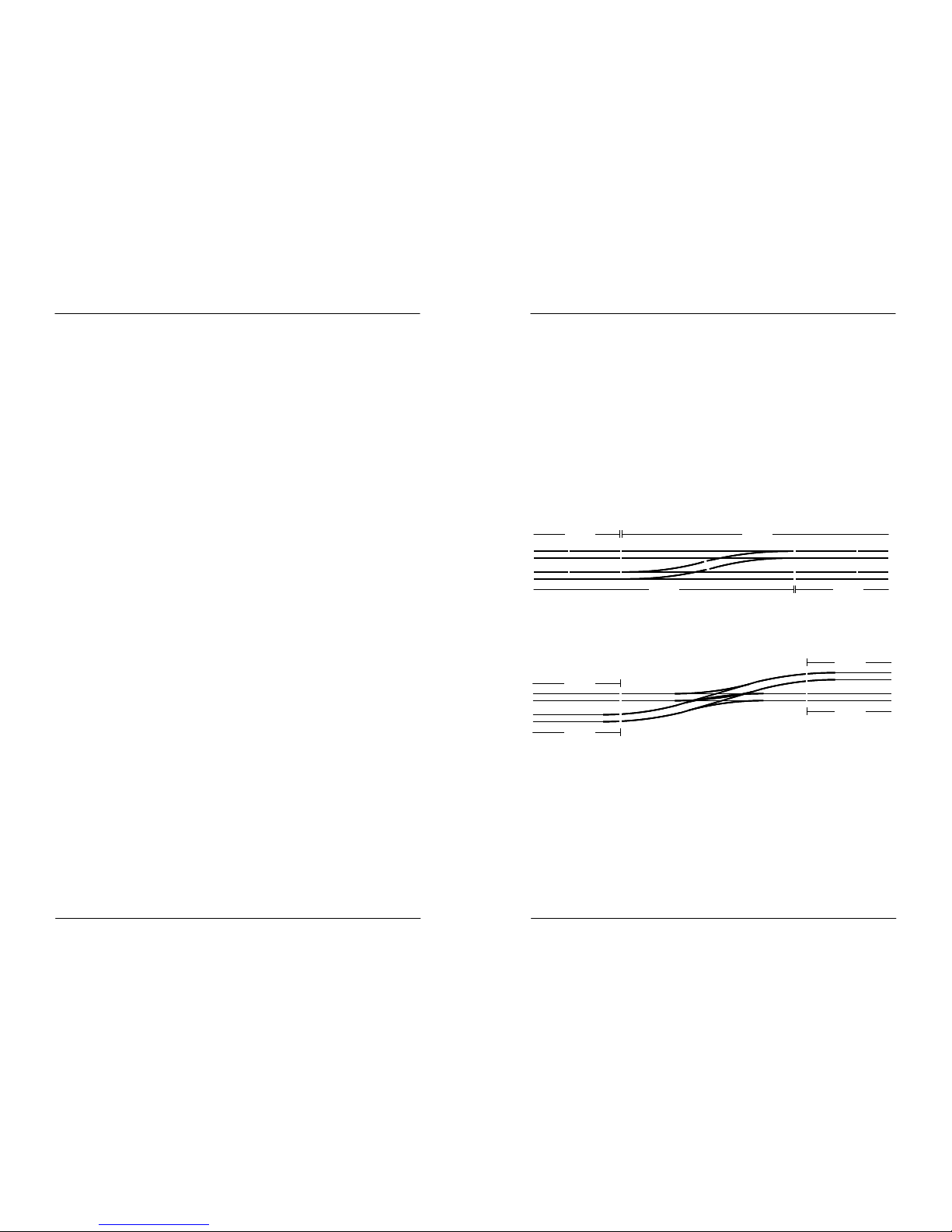
Since a turnout is never part of a block security-wise, it makes sense to assign a turnout
group that is fed from an adjacent block a separate section. If your softw are supports it, it
can then ‘see’ if the train is actually in the block itself or in the adjace nt turnout. In most
cases you’ll have sufficient sections available to do this.
Fig 33: Connected turnouts in separate sections
7.3 Addtitional Pseudo-blocks
In some cases a turnout cannot be passed to or from one single adj acent block only. An
example of such situation is the crossing turnout:
Fig 34: Crossing turnout
In the example above T1 can be passed from block 1 to block 2, but a lso from block 3 to
block 4. So there is no possibility to feed the tracks of T1 from either of the adjacent
blocks. There are two solutions for this problem:
1. Define T1 as a separate pseudo-block. Since a tu rnout is never part of any block this is
not a real block, but a piece of track that is powered separately as if it was a block.
2. Use a relay with 2 change-over contacts to conn ect the tracks on T1 to one of the
adjacent blocks, dependent on the selected route. See paragraph 7.4. In the above
example from figure 34, T1 can be connected to block 1 or block 2, becau se in any case
one of these blocks is part of the route the train follows.
Note that the capabilities of your control software may limit your cho ices to apply the above
options.
block 2
block 3
block 1
block 4
section 1.2 section 2.0
section 3.3section 3.2 section 4.0
section 2.1 section 2.2
section 4.1
section 1.1
section 3.1
block 2
block 3
block 1
block 4
section 1.2 section 2.0
section 3.3section 3.2 section 4.0
section 2.1 section 2.2
section 4.1
section 1.1
section 3.1
block 3
block 1
block 4
T1 block 2
block 3
block 1
block 4
T1 block 2
Manual DINAMO Plug & Play Control your miniature world
Page 28 of 32 Version 1.2 – Dec 21st, 2017 2017 Leon van Perlo
7 Turnouts
7.1 Provide track power to turnouts
As indicated in paragraph 1.1, turnouts and turnout-groups are not part of any block. The
rails on a turnout however will need power supply to allow the train to p ass over it. In a
Dinamo system a turnout usually is electrically attached to an adjacent bl ock when the
turnout can only be accessed when running to or from that block. As an example:
Fig 31: Attaching turnouts to an adjacent block
T1 can only be passed from or to block 2. So it is allowed to attach th e rails of T1
electrically to block 2. Also T2 can be passed only from or to block 3. Therefore it is allowed
to derive the power for T2 from block 3.
Rule: At the “sharp side” of a turnout (at the side where the track s join) there will
never be an electrical block-separation.
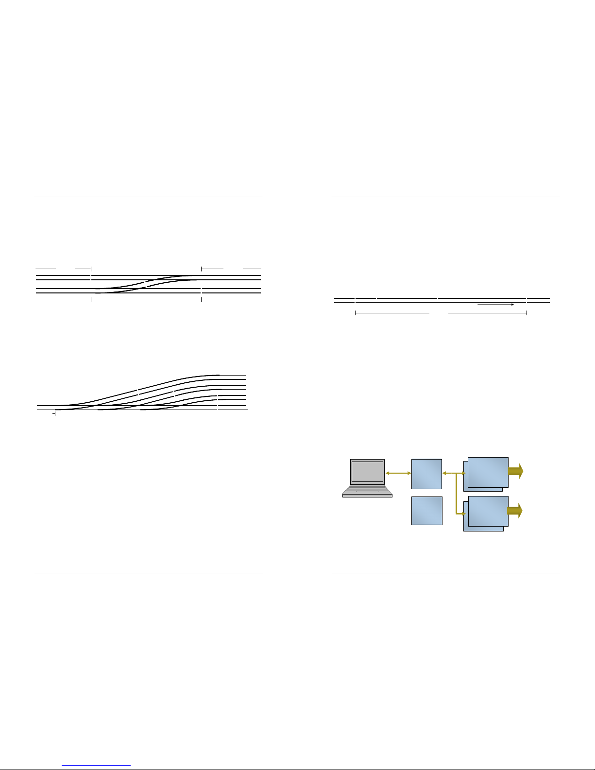
Even when multiple turnouts are lined up this rule counts. Have a look at the example in
figure 32:
Fig 32: Multiple turnouts in-line
T1, T2 and T3 all can only be accessed from or to block 1, so they are al l electrically
connected to block 1.
7.2 Turnout groups, Block Separations, Section Separations
The exact location where you make the block-separation is of no great importance to
Dinamo, however it may be important for your control software. Theref ore, read the
documentation of your control software product and/or make a test- layout before you apply
this to your target layout. Mind that a block separation is also a section separation by
definition, so it is a means for the software to determine where exact ly the train is. We
mention 2 important points of interest:
1. If you are using ‘full detection’, which means al l axles of all your rolling stock shall draw
some current from the tracks, your software can determine, if it sup ports this feature,
in which block and section something is present. So, for instance , your software can see
that a turnout-section is completely free before it is reserved for another train. In this
case it is important that ‘free’ means ‘truly free’ and not that the last tiny part of your
train still ‘hangs over’ the turnout. Therefore always keep some distan ce between the
block-separation and the adjacent turnout, as shown in figure 31.
Also if you do not use full detection, or if your software does not sup port it, it is good to
keep the above rule in mind. What is not the case now may become the ca se in the
future. Changing software is normally a lot easier than changing your physical layout.
block 2
block 3
block 1
block 4
T1
T2
block 2
block 3
block 1
block 4
T1
T2
block 2
block 1 T3T2T1
block 3
block 4
block 5
block 2
block 1 T3T2T1
block 3
block 4
block 5
Control your miniature world Manual DINAMO Plug & Play
2017 Leon van Perlo Version 1.2 – Dec 21st, 2017 Page 5 of 32
As a result, within one block, we have a continuous rail and a non-cont inuous rail split into
sections. Since every block offers the possibility to drive in both dire ctions and in case we
use digital (DCC) control, the signal is a square-wave alternating signa l it makes no sense to
talk about “plus” and “minus”. Therefore Dinamo talks about the A-rail and B-rail. The A-rail
always is continuous, the B-rail can be interrupted between sect ions. To identify the
direction in which the train travels, within Dinamo the “positive direct ion” is the direction
with the A-rail on the right hand side. To be clear: There is no need or r eason to have the
“positive direction” equal to the direction the train normally travels. “ Positive” and
“negative” directions are just names to identify in which way the tra in travels with respect
to the A-rail and B-rail. We explicitly do not use “forward” or “reverse” because this would
apply to the front and rear of the loco.
The general advise is to choose the rail in which you make the section-separations as
consistently as possible without taking into account normal direction of t ravel.
Fig 1: Subdivision of a block in a Dinamo system
1.3 Dinamo Plug & Play
Dinamo P&P consists of just 3 different modules, by which all pos sible parts of your layout
can be controlled, including analogue trains, digital trains, turnouts, signals and many other
accessories.
The modules that are part of the Plug & Play concept are:
•
RM-C/1+: This module handles communication with the PC, communi cation to all other
modules and ensures that all modules, for which this is necessar y, operate fully
synchronized;
•
TM44: This module controls trains and reads positions by mean s of current detection.
Each TM44 can drive 4 blocks and detects trains in 4 sections per b lock. Each system
(RM-C) can connect up to 32 TM44 modules for a total capacit y up to 128 blocks.
•
OC32(/NG): This module controls turnouts, signals, decouplers, railroad crossings and
virtually all other accessories you may find on your miniature world, requir ing control.
One system can host a maximum of 16 OC32 modules.
Schematically the topology looks as follows:
Fig 2: Dinamo P&P Diagram
A
B0 B1 B2 B3
block Nblock N-1 block N+1
positive direction
A
B0 B1 B2 B3
block Nblock N-1 block N+1
positive direction
OM32
RM-C
OC32/NG
Power
TM51
TM44
Trains
Turnouts
Signals
Decouplers
Scenery
…
 Loading...