


VTAC HSD USER MANUAL
TABLE OF CONTENTS
SECTION 1 VTAC HSD PART IDENTIFICATION
SECTION 2 VTAC HSD INSERT INSTALLATION/REMOVAL INSTRUCTIONS
SECTION 3 VTAC HSD RAILS INSTALLATION/REMOVAL INSTRUCTIONS
SECTION 4 VTAC HSD 90 SERIES MODULES INSTALLATION/REMOVAL INSTRUCTIONS
SECTION 5 VTAC HSD ACCESSORIES
SECTION 6 SIM RIGHT ANGLE INSERT PART IDENTIFICATION
SECTION 7 SIM RIGHT ANGLE INSERT INSTALLATION/REMOVAL INSTRUCTIONS
SECTION 8 SMALL PCB AND RETENTION INSERT USAGE
SECTION 9 VTAC HSD VERTICAL INSERT PART IDENTIFICATION
SEC TION 10 VTAC HSD VERTICAL INSERT PCB INSTALLATION INSTRUCTIONS
SEC T ION 11 TROUBLESHOOTING
SECTION 12 PRODUCT PERFORMANCE SPECIFICATIONS
Please note that any printed or downloaded User Manuals or Procedure Sheets may not reect the
most current revisions. The information contained in these materials is subject to change.
For the most current information available, visit vpc.com.
1/9/19
VTAC HSD USER MANUAL: SECTION 1 VIRGINIA PANEL CORPORATION
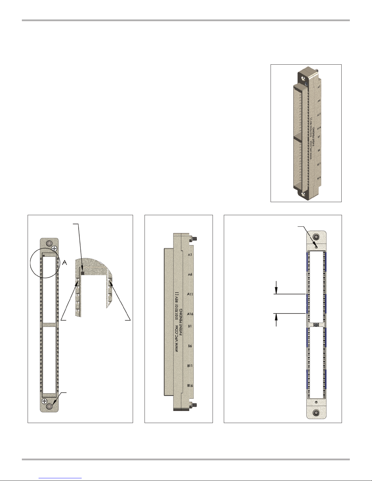
VTAC HSD 90 SERIES RECEIVER MODULE PART IDENTIFICATION
PART # 510 170 101
This section will point out features designed to help determine the proper orientation
of the VTAC HSD 90 Series receiver module (Figure A), as well as distinguishing
features.
The top of the VTAC HSD 90 Series receiver module can be determined by the position
A1 indicator, designated by the notch shown in Figure B. When the module is oriented
correctly, the position A1 notch will be visible in the upper left corner.
The front and rear of the VTAC HSD 90 Series receiver module are shown in Figure C.
The front has the position A1 notch. The front side mates with the VTAC HSD 90 Series
ITA module.
The rear of the VTAC HSD 90 Series receiver module has silkscreening along the side.
Wires exit the VTAC HSD 90 Series receiver module from the rear side.
NOTE: The blue silkscreen indicates ve slot positions, as shown in Figure D.
POSITION A1
INDICATOR
TOP
EXTRACTION TOOL CAVITY
DETAIL A
FRONT
MATING
SIDE
REAR
WIRING
SIDE
Figure A. Receiver Module.
2-56 TAPPED HOLES FOR
STRAIN RELIEF PLATE SCREWS
TYP. 2 PLCS
INDICATES 5 POSITIONS
MOUNTING SCREWS
TYP. 2 PLCS
BOTTOM
Figure B. Receiver module front view
(mating side).
1-1 For the most current information available, visit vpc.com
Figure C. Receiver module
side view.
Figure D. Receiver module
rear view (wiring side).
1/9/19
VTAC HSD USER MANUAL: SECTION 1 VIRGINIA PANEL CORPORATION
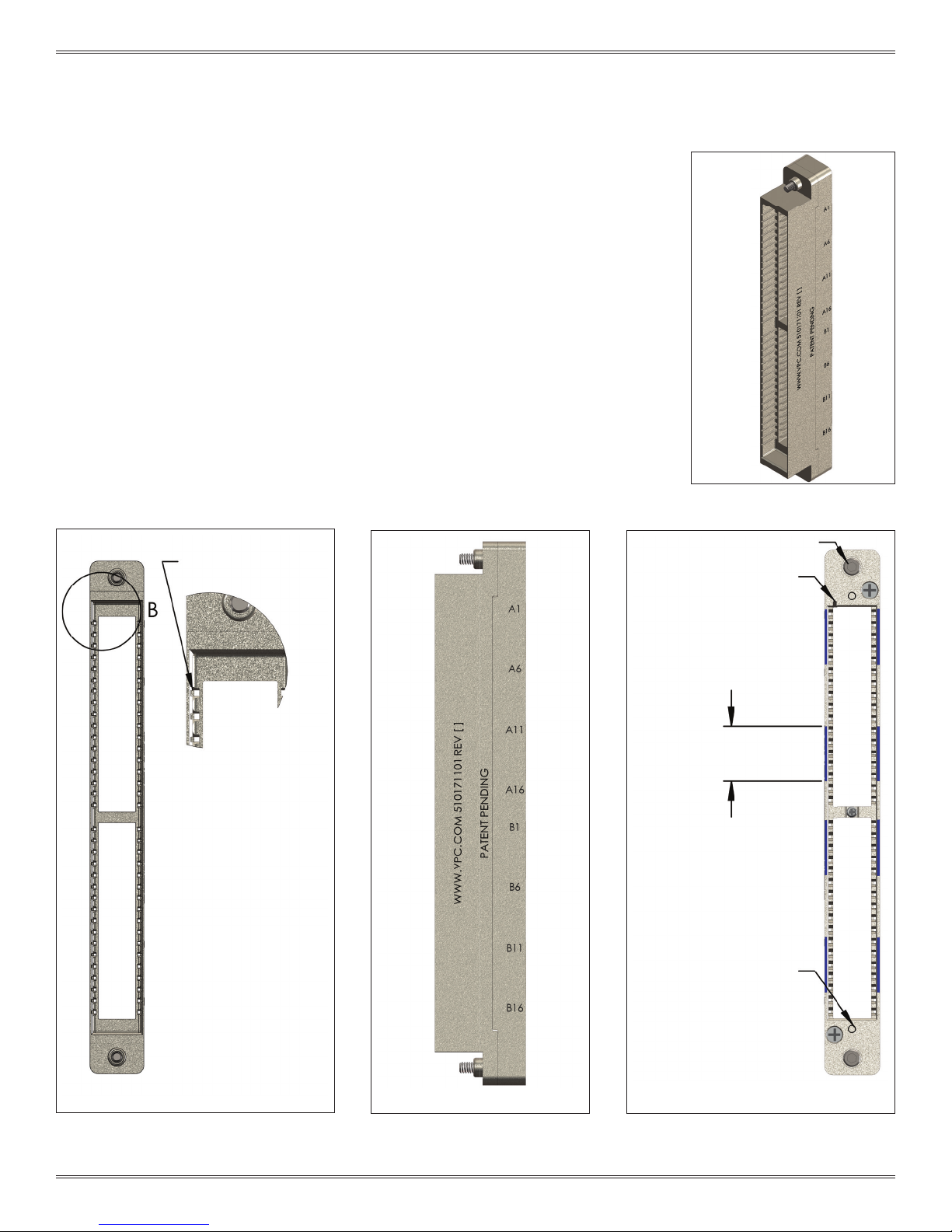
VTAC HSD 90 SERIES ITA MODULE PART IDENTIFICATION
PART # 510 171 101
This section will point out features designed to help determine the proper orientation
of the VTAC HSD 90 Series ITA module (Figure A), as well as distinguishing features.
The top of the VTAC HSD 90 Series ITA module (Figure B) can be determined by the
position A1 indicator on the rear side, designated by the notch shown in Figure D.
When the module is oriented correctly, the position A1 notch will be visible in the
upper left corner.
The front and rear of the VTAC HSD 90 Series ITA Module are shown in Figure C. The
front mates with the VTAC HSD 90 Series Receiver Module.
The rear has the position A1 notch. The rear of the VTAC HSD 90 Series ITA module has
silkscreening along the side (Figure D). Wires exit the VTAC HSD 90 Series ITA module
from the rear side.
NOTE: The blue silkscreen indicates ve slot positions, as shown in Figure D.
TOP
EXTRACTION TOOL CAVITY
DETAIL B
FRONT
MATING
SIDE
Figure A. ITA module.
MOUNTING SCREWS TYP. 2 PLCS
POSITION A1 INDICATOR
INDICATES 5 POSITIONS
REAR
WIRING
SIDE
BOTTOM
Figure B. ITA module front view
(mating side).
1-2 For the most current information available, visit vpc.com
Figure C. ITA module side
vi ew.
2-56 TAPPED HOLES FOR
STRAIN RELIEF PLATE SCREWS
TY. 2 PLCS
Figure D. ITA module rear
view (wiring side).
1/9/19
VTAC HSD USER MANUAL: SECTION 1 VIRGINIA PANEL CORPORATION
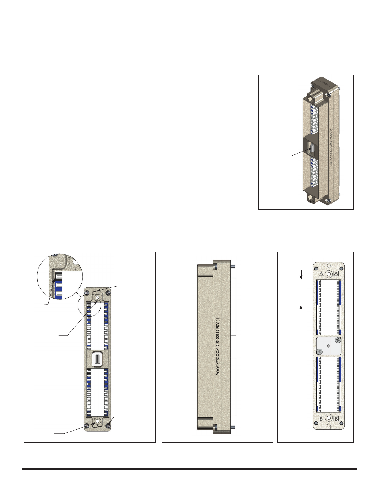
i2 MX RECEIVER PART IDENTIFICATION
PART # 310 130 XXX
Figure B points out distinguishing features of the i2 MX receiver so that the top and
bottom can be identied. Features to look for are the numeric keying receptacle at
the top and the alpha keying receptacle on the bottom.
When holding the i2 MX receiver, the top can be determined when the letters and
numbers are oriented as shown in Figure B. The top position is designated by a black
marking around the upper slot in Tier A and Tier B module locations (Figure B).
The front and rear of the i2 MX receiver are shown in Figure C. The front has a
polarizing feature which prevents the ITA and receiver from being engaged in the
incorrect orientation. The front of the i2 MX receiver can be identied as the side with
the latching feature (Figure A).
Figure D shows the rear silkscreen that aides in indicating positions.
The front side mates with the i2 MX ITA. Wires exit the i2 MX receiver from the rear side.
LATCHING
FEATURE
POSITION
A1
INDICATOR
NUMERIC KEYING
RECEPTACLE
TOP
TIER A
TIER B
POLARIZING
FEATURE
FRONT
MATING
SIDE
Figure A. i2 MX receiver
INDICATES 5
POSITIONS
REAR
WIRING
SIDE
MOUNTING
SCREWS TYP. 4
PLCS
ALPHA KEYING
RECEPTACLE
BOTTOM
Figure B. i2 MX receiver front view.
1-3 For the most current information available, visit vpc.com
Figure C. i2 MX receiver side view.
Figure D. i2 MX receiver rear
vi ew.
1/9/19
VTAC HSD USER MANUAL: SECTION 1 VIRGINIA PANEL CORPORATION
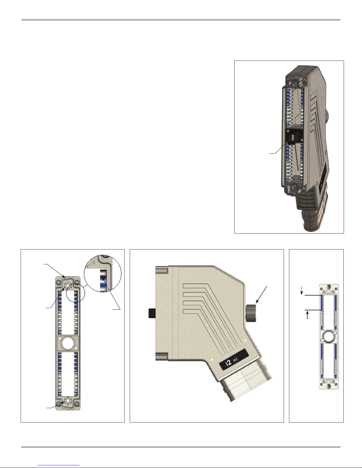
i2 MX ITA PART IDENTIFICATION
PART # 410 130 XXX
Figure B points out distinguishing features of the i2 MX ITA so that the top and bottom
can be identied. Features to look for are the numeric keying receptacle at the top
and the alpha keying receptacle on the bottom.
When holding the i2 MX ITA, the top can be determined when the letters and numbers
are readable. The top position is designated by a black marking around the upper slot
in Tier A and Tier B module locations (Figure B).
The front and rear of the i2 MX ITA are easily distinguished as shown in Figure C. The
front has a protruding guide plate with locking tabs (Figure A) and the rear has the
knob.
Figure D shows the rear silkscreen that aides in indicating positions.
The front side mates with the i2 MX receiver. The front has a polarizing feature which
prevents the ITA and receiver from being engaged in the incorrect orientation. Wires
exit the i2 MX ITA through the 30° cable exit (Figure C).
POLARIZING
FEATURE
NUMERIC
KEYING
RECEPTACLE
TOP
POSITION A1
INDICATOR
TIER A
FRONT
MATING
SIDE
LOCKING TABS
Figure A. i2 MXITA
KNOB
INDICATES 5
POSITIONS
REAR
WIRING
SIDE
TIER B
ALPHA
KEYING
RECEPTACLE
Figure B. i2 MX ITA front view (backshell removed)
BOTTOM
1-4 For the most current information available, visit vpc.com
Figure C. i2 MX ITA side view.
30° CABLE EXIT
Figure D. i2 MX ITA rear
view (backshell
removed).
1/9/19
VTAC HSD USER MANUAL: SECTION 2 VIRGINIA PANEL CORPORATION
VTAC HSD INSERT INSTALLATION/REMOVAL INSTRUCTIONS
TOOLS REQUIRED
VTAC Extraction Tool Kit, Receiver and ITA, Part # 910 112 130
VTAC HSD INSERT INSTALLATION INSTRUCTIONS
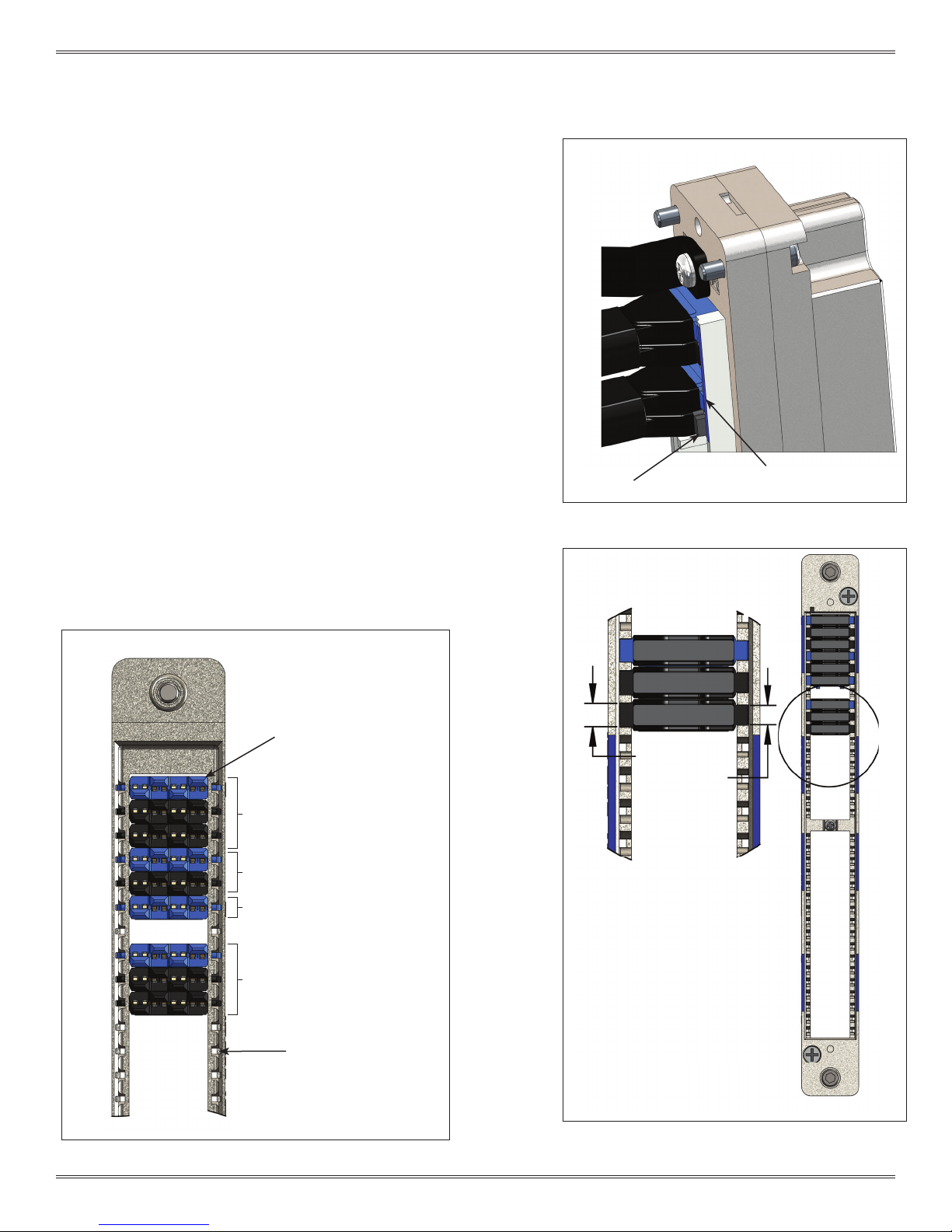
When inserting a VTAC HSD Insert stack, the blue insert is on top as shown
1.
in Figure B. Inserts are fully seated when the back of the inserts are ush
with the module (Figure A).
VTAC HSD INSERT REMOVAL INSTRUCTIONS
1. Group the required number of extraction tools together for the given VTAC
HSD patchcord. For example, a USB 3.0 patchcord requires two tools as
shown in Figure B.
WARNING: All inserts within each patchcord must be extracted simultaneously
to prevent damage to VTAC HSD Inserts.
NOTE: The extraction tools are magnetic to aid in stacking them together.
2. The indivdual patchcords can be identi ed by a blue insert, indicating the
beginning of a new stack or single insert patchcord as shown in Figure B.
NOTE: The slots on one side of the module are a slightly
different width than the other side to ensure the insert is
oriented correctly, as shown in Detail C in Figure C.
NOT FLUSH
Figure A. VTAC Insert alignment.
FLUSH
NOTE: For patchcords with more than 3 inserts, multiple VTAC tool kits (910 112
130) will be required.
BLUE INSERT
EXAMPLE OF A HDMI PATCHCORD
3 EXTRACTION TOOLS REQUIRED
EXAMPLE OF AN USB PATCHCORD
2 EXTRACTION TOOLS REQUIRED
SINGLE PATCHCORD 1 EXTRACTION
TOOL REQUIRED
EXAMPLE OF A HDMI PATCHCORD
3 EXTRACTION TOOLS REQUIRED
DETAIL C
C
Y1 LARGE SIDE
Y2 SMALL SIDE
EXTRACTION TOOL CAVITY
MATING FACE
Figure B. VTAC HSD Insert install and removal detail (ITA Shown).
2-1 For the most current information available, visit vpc.com
WIRING SIDE
Figure C. VTAC HSD Inser t install and removal detail (ITA
Shown).
1/9/19
VTAC HSD USER MANUAL: SECTION 2 VIRGINIA PANEL CORPORATION
VTAC HSD INSERT INSTALLATION/REMOVAL INSTRUCTIONS FOR RECEIVER MODULE
PART # 510 170 101
TOOLS REQUIRED
VTAC Extraction Tool Kit, Receiver and ITA, Part # 910 112 130
VTAC HSD INSERT INSTALLATION INSTRUCTIONS
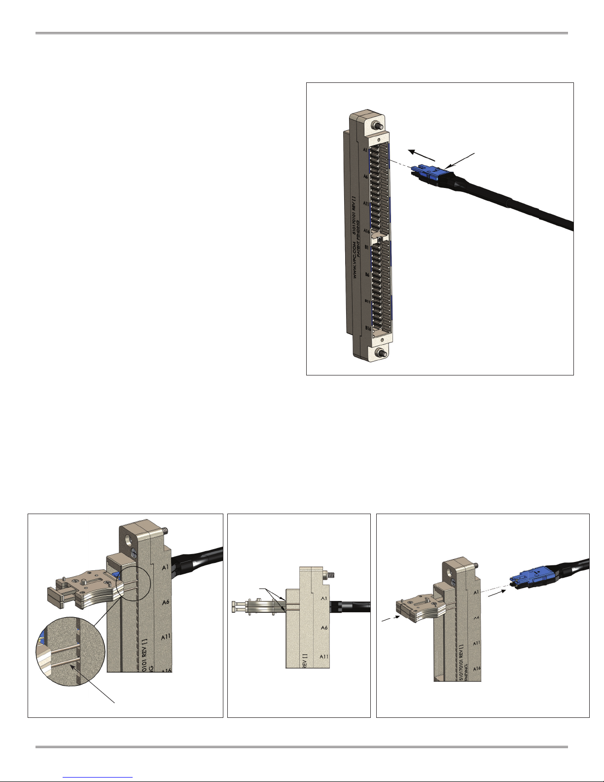
Ensure that the VTAC HSD Insert(s) is in-line with the
1.
corresponding module location. Apply gentle pressure and
insert the VTAC HSD Insert(s) into the rear (wiring side) of the
module shown in Figure A. The VTAC HSD Insert(s) can only go
into one side. Once in place, gently pull the wire to ensure
the insert(s) is fully seated.
NOTE: To be fully seated, the insert(s) back shoulder should be ush
or below the module rear face as shown in Section 2-1 Figure C.
When plugging a stack of inserts, the blue insert will always be on
top as shown in Section 2-1 Figure A.
VTAC HSD INSERT REMOVAL INSTRUCTIONS
1. Group the required number of extraction tools together for
the given VTAC HSD patchcord shown in Figure B. The tool
pins should be on the mating side of the module.
BLUE INSERT
WARNING: All inserts within each patchcord must be extracted
simultaneously to prevent damage to VTAC HSD Inserts.
NOTE: The extraction tools are magnetic to aid in stacking them
together.
2. While grasping the extraction tool(s) body from the sides
(Figure B), slide tool pins into module’s extraction cavity
square holes until the tool frame is seated against the body
shown in Figure C.
WARNING: The extraction tool(s) need to be seated against
the module front face before the plunger is pushed in. Otherwise
damage to insert(s) may occur.
3. Push plunger of extraction tool(s) in to extract VTAC HSD
Insert(s). The insert(s) will be ejected out the wiring side of the
module shown in Figure D.
PLUNGER
GRIP
SEAT
Figure A. VTAC HSD Insert installation.
EXTRACTION TOOL
DETAIL A
Figure B. Inser t removal tool pins.
PINS
2-2 For the most current information available, visit vpc.com
Figure C. Seat removal tool
to module frame.
PUSH
PLUNGER
Figure D. Push removal tool plunger.
1/9/19
VTAC HSD USER MANUAL: SECTION 2 VIRGINIA PANEL CORPORATION
VTAC HSD INSERT INSTALLATION/REMOVAL INSTRUCTIONS FOR ITA MODULE
PART # 510 171 101
TOOLS REQUIRED
VTAC Extraction Tool Kit, Receiver and ITA, Part # 910 112 130
VTAC HSD INSERT INSTALLATION INSTRUCTIONS
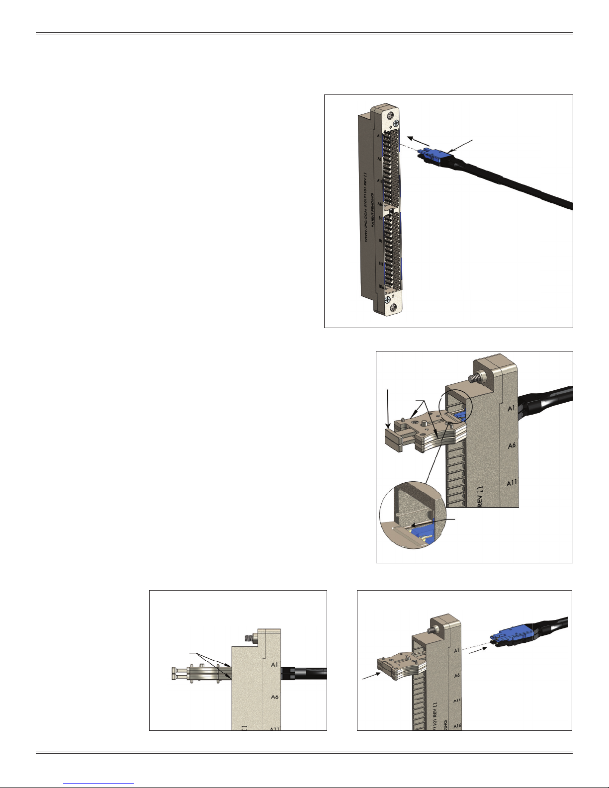
Ensure that the VTAC HSD Insert(s) is squared up with the
1.
corresponding module location. Apply gentle pressure and insert
the VTAC HSD Insert(s) into the rear (wiring side) of the module
shown in Figure A. The VTAC HSD Insert(s) can only go into one
side. Once in place, gently pull the wire to ensure the insert(s) is
fully seated.
NOTE: To be fully seated, The insert(s) back shoulder should be ush or
below the module rear face as shown in Section 2-1 Figure C. When
plugging a stack of inserts, the blue insert will always be on top as
shown in Section 2-1 Figure A.
VTAC HSD INSERT REMOVAL INSTRUCTIONS
1. Group the required number of extraction tools together for the
given VTAC HSD patchcord shown in Figure B. The tool pins should
be on opposite sides of the patchcords or wires to be removed.
WARNING: All inserts within each patchcord must be extracted
simultaneously to prevent damage to VTAC HSD Inserts.
NOTE: The extraction tools are magnetic to aid in stacking them
together.
2. While grasping the extraction tool(s) body from the sides, (Figure
B), slide tool pins into module’s extraction cavity slots until the tool
frame is seated against the body shown in Figure C.
BLUE INSERT
Figure A. VTAC HSD insert installation.
PLUNGER
GRIP
WARNING: The extraction tool(s) need to be seated against the
module front face before the plunger is pushed in. Otherwise
damage to insert(s) may occur.
3. Push plunger of extraction tool(s) in to extract VTAC HSD Insert(s).
The insert(s) will be ejected out the wiring side of the module
shown in Figure D.
SEAT
EXTRACTION TOOL
PINS
DETAIL A
Figure B. Inser t removal tool pins.
PUSH
PLUNGER
Figure C. Seat removal tool to module frame.
2-3 For the most current information available, visit vpc.com
Figure D. Push removal tool plunger.
1/9/19
VTAC HSD USER MANUAL: SECTION 2 VIRGINIA PANEL CORPORATION
VTAC HSD INSERT INSTALLATION/REMOVAL INSTRUCTIONS FOR i2 MX RECEIVER
PART # 310 130 XXX
TOOLS REQUIRED
VTAC Extraction Tool Kit, Receiver and ITA, Part # 910 112 130
VTAC HSD INSERT INSTALLATION INSTRUCTIONS
Ensure that the VTAC HSD Insert(s) is squared up with the
1.
corresponding module location. Apply gentle pressure and insert the
VTAC HSD Insert(s) into the rear (wiring side) of the module shown in
Figure A. The VTAC HSD Insert(s) can only go into one side. Once in
place, gently pull the wire to ensure the insert(s) is fully seated.
NOTE: To be fully seated, The insert(s) back shoulder should be ush or
below the module rear face as shown in Section 2-1 Figure C. When
plugging a stack of inserts, the blue insert will always be on top as shown in
Section 2-1 Figure A.
VTAC HSD INSERT REMOVAL INSTRUCTIONS
1. Group the required number of extraction tools together for the given
VTAC HSD patchcord shown in Figure B. The tool pins should be on
opposite sides of the patchcords or wires to be removed.
BLUE INSERT
WARNING: All inserts within each patchcord must be extracted
simultaneously to prevent damage to VTAC HSD Inserts.
NOTE: The extraction tools are magnetic to aid in stacking them together.
2. While grasping the extraction tool(s) body from the sides (Figure B).
slide tool pins into module’s extraction cavity slots until the tool frame
is seated against the body shown in Figure C.
3. Push plunger of extraction tool(s) in to extract VTAC HSD Insert(s). The
insert(s) will be ejected out the wiring side of the module shown in
Figure D.
GRIP
Figure B. Inser t Removal.
SEAT
Figure A. VTAC HSD Insert installation
WARNING: The extraction tool(s) need to be seated against
the module front face before the plunger is pushed in. Otherwise damage to insert(s) may occur.
PUSH
PLUNGER
Figure C. Seat Removal tool
2-4 For the most current information available, visit vpc.com
PLUNGER
Figure D. Push removal tool plunger.
1/9/19
VTAC HSD USER MANUAL: SECTION 2 VIRGINIA PANEL CORPORATION
VTAC HSD INSERT INSTALLATION/REMOVAL INSTRUCTIONS FOR i2 MX ITA
PART # 410 130 XXX
TOOLS REQUIRED
VTAC Extraction Tool Kit, Receiver and ITA, Part # 910 112 130
VTAC HSD INSERT INSTALLATION INSTRUCTIONS
Ensure that the VTAC HSD Insert(s) is squared up with the
1.
corresponding module location. Apply gentle pressure
and insert the VTAC HSD Insert(s) into the rear (wiring
side) of the module shown in Figure A. The VTAC HSD
Insert(s) can only go into one side. Once in place, gently
pull the wire to ensure the insert(s) is fully seated.
NOTE: To be fully seated, The insert(s) back shoulder should
be ush or below the module rear face as shown in Section
2-1 Figure C. When plugging a stack of inserts, the blue insert
will always be on top as shown in Section 2-1 Figure A.
NOTE: Backshell removal instructions start in Section 2-6.
BLUE INSERT
NOTE: For i2 MX ITA Cable Assembly and Backshell Installation
Instructions, refer to the i2 MX User’s manual Section 5.
NOTE: To take advantage of the larger area for bend radius,
it is recommended to plug VTAC patchcords in Tier A as
shown in Section 1-4 Figure B.
Figure A. VTAC HSD Insert installation
2-5 For the most current information available, visit vpc.com
1/9/19
VTAC HSD USER MANUAL: SECTION 2 VIRGINIA PANEL CORPORATION
VTAC HSD INSERT REMOVAL INSTRUCTIONS FOR i2 MX ITA
PART # 410 130 XXX
TOOLS REQUIRED
Phillips Head Screwdriver
Flat Head Screwdriver
1/4” Nut Driver, hollow shaft
VTAC Extraction Tool Kit, Receiver and ITA, Part # 910 112 130
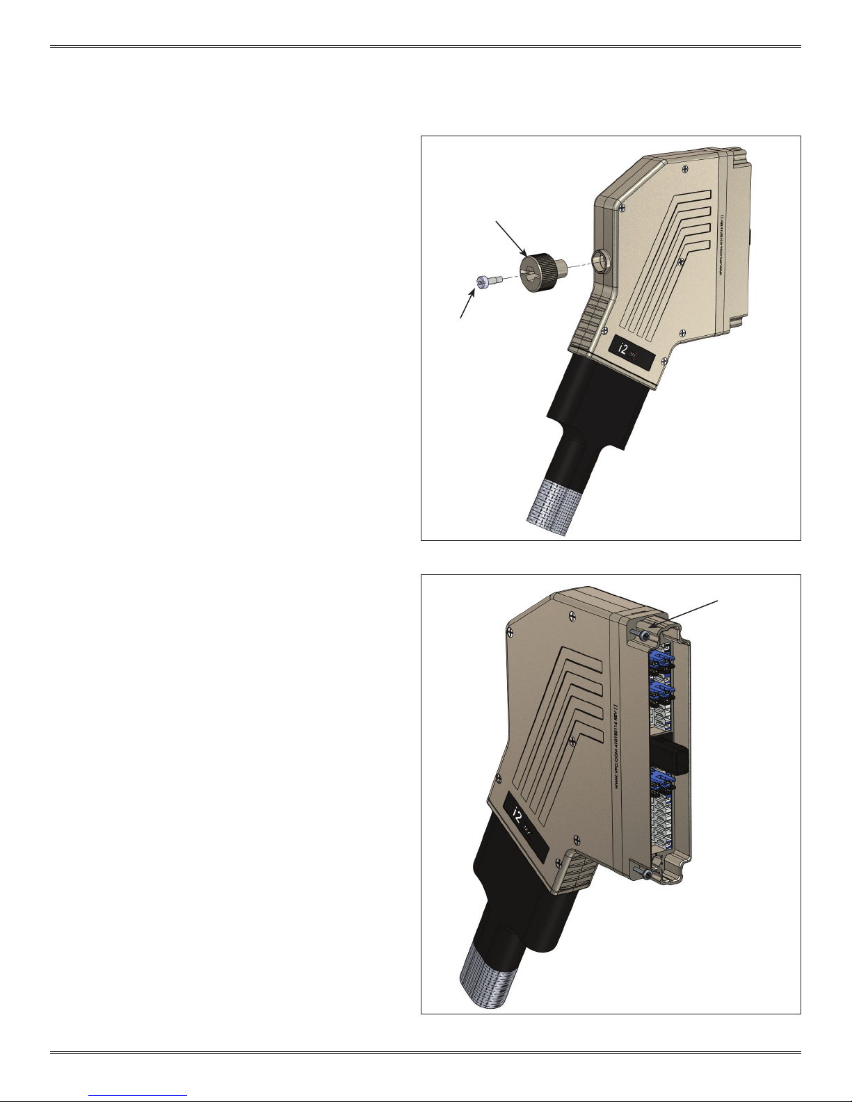
REMOVAL INSTRUCTIONS
1. Disengage the ITA from the receiver.
2. Using a at head screwdriver, remove the engagement
knob screw and engagement knob (Figure A).
3. Using a Phillips head screwdriver, loosen the four screws
(captive) that secure the backshell to the ITA frame
(Figure B).
KNOB SCREW
KNOB
Figure A. ITA knob removal.
FRA ME TO
BACKSHELL
SCREWS
2-6 For the most current information available, visit vpc.com
Figure B. Remove frame to backshell screws.
1/9/19

VTAC HSD USER MANUAL: SECTION 2 VIRGINIA PANEL CORPORATION
VTAC HSD INSERT REMOVAL INSTRUCTIONS FOR i2 MX ITA
PART # 410 130 XXX
REMOVAL INSTRUCTIONS (CONTINUED)
4. Using a Phillips head screwdriver, loosen the six screws
(captive) that secure the backshell halves. Remove the
half with the screws (Figure C).
5. Using a nut driver remove nuts on the strain relief clamp,
then remove the clamp (Figure D).
BACKSHELL
SCREWS
Figure C. Backshell cover removal.
NUT
STRAIN RELIEF
CLAMP
Figure D. Strain relief clamp removal.
2-7 For the most current information available, visit vpc.com
1/9/19

VTAC HSD USER MANUAL: SECTION 2 VIRGINIA PANEL CORPORATION
VTAC HSD INSERT REMOVAL INSTRUCTIONS FOR i2 MX ITA
PART # 410 130 XXX
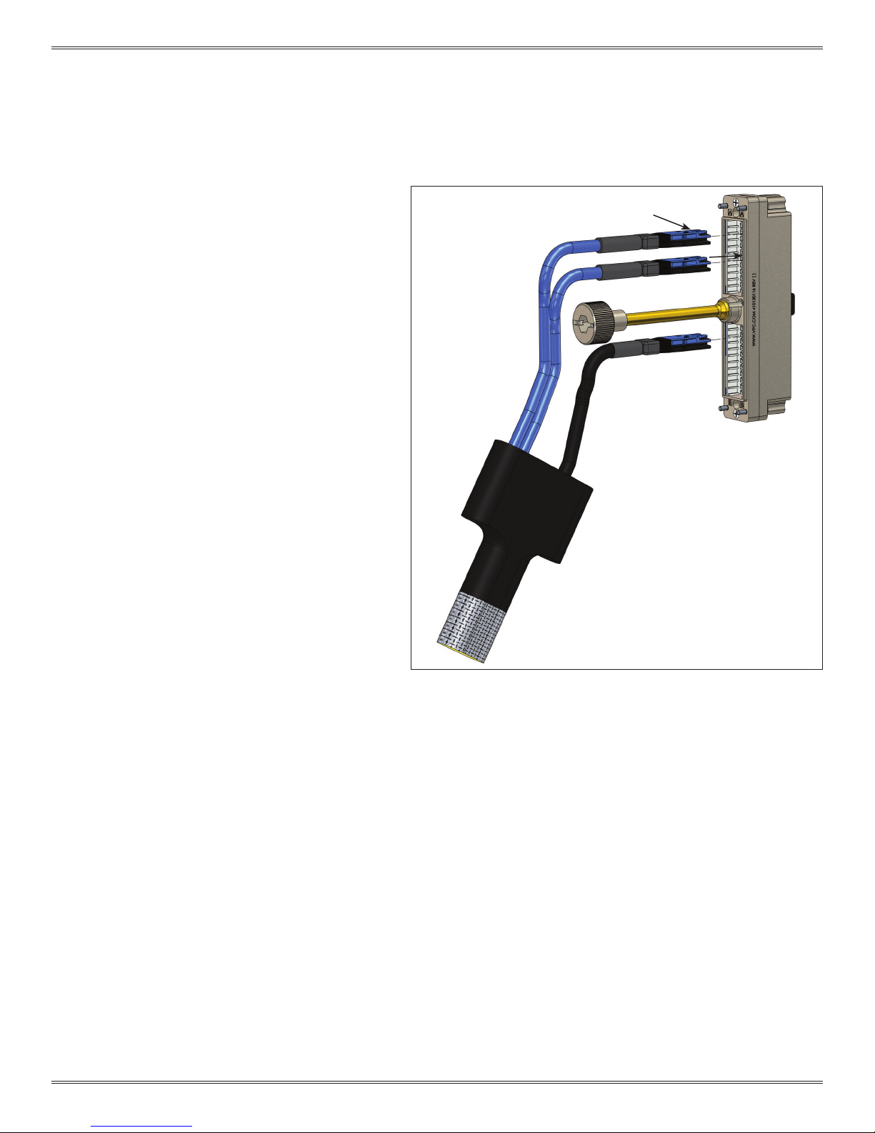
VTAC HSD INSERT REMOVAL INSTRUCTIONS (CONTINUED)
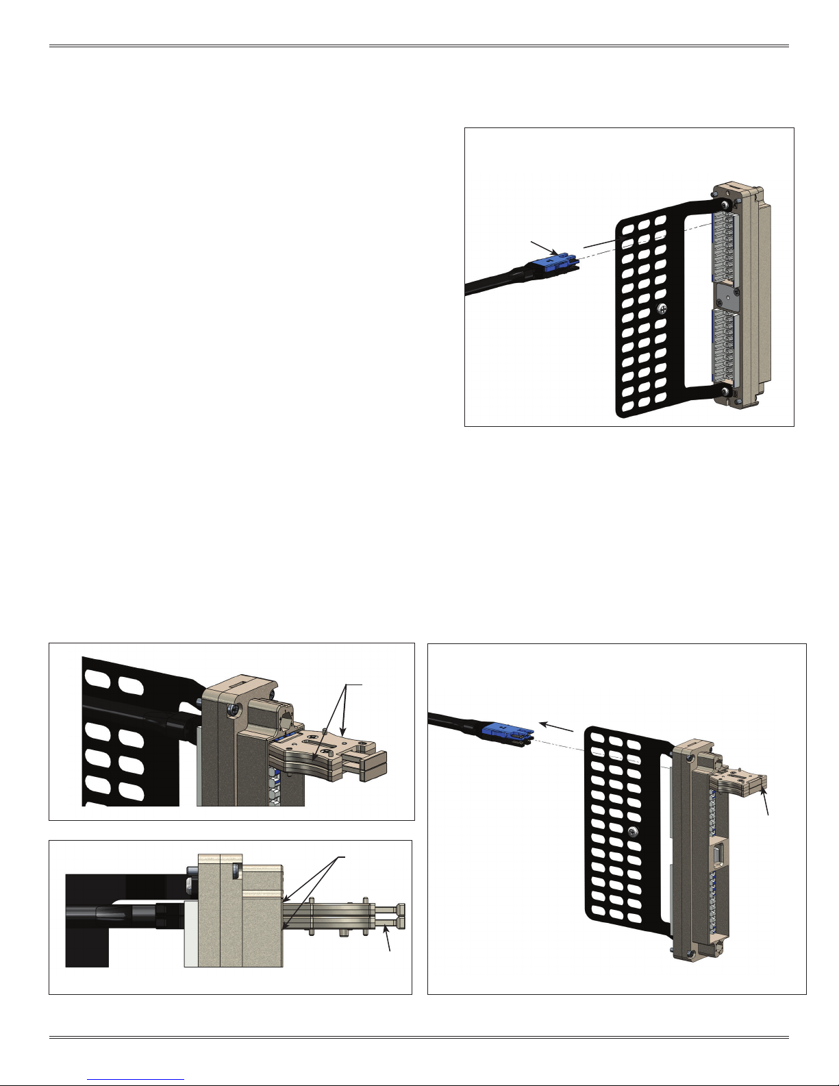
1. Group the required number of extraction tools
together for the given VTAC HSD patchcord shown in
Figure E. The tool pins should be on opposite sides of
the patchcords or wires to be removed.
WARNING: All inserts within each patchcord must be
extracted simultaneously to prevent damage to VTAC HSD
Inserts.
SEATE D
FLUSH
NOTE: The extraction tools are magnetic to aid in stacking
them together.
2. While grasping the extraction tool(s) body from the
sides (Figure E), slide tool pins into module’s extraction
cavity slots until the tool plunger is ush with the tool
body and the plunger is in contact with the VTAC HSD
insert tips shown in Figure E.
WARNING: The extraction tool(s) need to be seated against
the module front face before the plunger is pushed in.
Otherwise damage to insert(s) may occur.
3. Push plunger of extraction tool(s) in to extract VTAC
HSD Insert(s). The insert(s) will be ejected out the wiring
side of the module shown in Figure F.
GRIP
PLUNGER
Figure E. Seat removal tool.
2-8 For the most current information available, visit vpc.com
PUSH
PLUNGER
Figure F. Inser t removal.
1/9/19

VTAC HSD USER MANUAL: SECTION 3 VIRGINIA PANEL CORPORATION
VTAC HSD RAIL(S) INSTALLATION/REMOVAL INSTRUCTIONS
PART # 310 130 XXX AND 410 130 XXX
TOOLS REQUIRED
Phillips Head Screwdriver
VTAC HSD RAIL(S) REMOVAL INSTRUCTIONS
1. If working with a receiver, use a Phillips head screwdriver to
remove strain relief by removing screws (Figure A).
The ITA will require removal of backshell rst. See Section 2 of this
User’s Manual for instructions.
2. After removing strain relief/backshell, use a Phillips head
screwdriver to remove the two Phillips at head screws that are
holding the frame halves together (Figure A).
For ITA use Phillips head screwdriver to loosen the two captive
screws on the back of the rear frame (Figure B).
3. Pull halves apart.
4. Remove VTAC HSD Rail(s).
VTAC HSD RAIL(S) INSTALLATION INSTRUCTIONS
1. To install VTAC HSD Rail(s), orient rail(s) as shown in (Figure A).
Figure C illustrates the identiers to aid in orientation (receiver rails
shown). The receiver rails are marked with ‘RR’ (receiver right)
and ‘RL’ (receiver left) when viewing from mating face. The ITA
rails are marked with ‘IR’ (ITA right) and ‘IL’ (ITA left) when viewing
from rear/wiring side.
2. Place rail(s) ledge on at surface shown in (Figure D), then put
halves together and tighten the two Phillips at head screws using
a Phillips head screwdriver.
NOTE: Receiver/ITA frame halves are keyed to be placed together
only one direction.
PHILLIPS
FLAT HEAD
SCREWS (2)
TOP OF
RAIL
Figure A. VTAC HSD Rail(s) install/removal (receiver shown).
PHILLIPS
CAPTIVE
SCREWS (2)
Figure B. ITA frame separation.
3-1 For the most current information available, visit vpc.com
BLACK POSITION
AI I NDICATOR
‘RL’ RECEIVER
LEFT
Figure C. VTAC HSD Rail(s) - Identiers.
‘RR’ RECEIVER
RIGHT
TOP
BOTTOM
FLAT SURFACE
Figure D. VTAC HSD Rail(s) install/removal
(receiver shown).
1/9/19

VTAC HSD USER MANUAL: SECTION 4 VIRGINIA PANEL CORPORATION
VTAC HSD 90 SERIES MODULES INSTALLATION/REMOVAL INSTRUCTIONS
TOOLS REQUIRED
3
/32 Allen Wrench
INSTALLATION INSTRUCTIONS
1. Place the module in the receiver or ITA until the upper
and lower module screws touch the mating holes in
the inner frame (Figure A & B). Ensure that position A1 is
located at the top for systems in which the modules are
oriented vertically or to the left for systems in which the
modules are oriented horizontally.
2. Using a 3/32 Allen wrench, tighten the top screw 1 to 2 full
revolutions, while pushing lightly against the face of the
module.
3. Maintain this pressure while tightening the bottom screw 1
to 2 full revolutions.
4. Repeat this sequence until the module is seated. Torque
the screws to 4 in-lbs [0.45 Nm].
REMOVAL INSTRUCTIONS
1. To remove, loosen the top screw 1 to 2 full revolutions.
Loosen bottom screw 1 to 2 full revolutions.
2. Repeat this sequence until the module is separated from
the receiver or ITA.
NOTE: For optimum performance and system longevity,
distribute the contact load evenly throughout the module.
Figure A. Receiver module.
Figure B. ITA module.
4-1 For the most current information available, visit vpc.com
1/9/19

VTAC HSD USER MANUAL: SECTION 5 VIRGINIA PANEL CORPORATION
VTAC HSD 90 SERIES MODULES ACCESSORIES ● RECEIVER STRAIN RELIEF ASSEMBLY
PART # 510 109 568
TOOLS REQUIRED
Phillips Head Screwdriver
Wiring Ties
Wire Cutters (to cut wire ties)
ASSEMBLY INSTRUCTIONS
1. Using the Phillips head screwdriver, fasten the strain relief to
the rear (wiring) side of the VTAC HSD 90 Series Module with
the 2-56 screws provided as shown in Figure A.
2. Torque screws to 2 in-lbs [0.23 Nm].
3. Secure wires with wiring ties included with strain relief for
restraining wires.
NOTE: Strain relief is required for optimal performance.
STRAIN RELIEF
2-56 SCREW
5-1 For the most current information available, visit vpc.com
Figure A. VTAC HSD 90 Series strain relief.
1/9/19

VTAC HSD USER MANUAL: SECTION 6 VIRGINIA PANEL CORPORATION
REAR
VTAC HSD DOUBLE ENDED INSERT PART IDENTIFICATION
PART # 610 151 103
This section will point out features designed to help determine the proper orientation of the VATC HSD Double Ended Insert (Figure A),
as well as distinguishing features.
The Front Mating Side of the VATC HSD Double Ended Insert is shown in Figure A. The Rear Mating Side is shown in Figure B. The Rear
Mating Side mates with the VTAC HSD Right Angle Insert.
The Pin 1 position is shown in Figure C. The VATC HSD Double Ended Insert is keyed with a large and small side to ensure the insert is
oriented correctly and can only be inserted into a module one way as shown in Figure C.
PIN 1
FRONT
MATING
SIDE
Figure A. VTAC HSD Double Ended Insert.
PIN 1
LARGE SIDE
(Keying)
Figure B. VTAC HSD Double Ended Insert (Rear Mating Side).
PIN 8
SMALL SIDE
(Keying)
REAR
MATING
SIDE
Figure C. VTAC HSD Double Ended Insert (Front Mating View).
6-1 For the most current information available, visit vpc.com
1/9/19

VTAC HSD USER MANUAL: SECTION 6 VIRGINIA PANEL CORPORATION
VTAC HSD RIGHT ANGLE INSERT PART IDENTIFICATION
PART # 610 151 104
This section will point out features designed to help determine the proper orientation
of the VTAC HSD Right Angle Insert (Figure A), as well as distinguishing features.
The top of the VTAC HSD Right Angle Insert is opposite the Compliant Pins shown in
Figure A.
The Compliant Pins and PCB Mounting Surface mates with the PCB. The Compliant
Pins and PCB Mounting Surface is shown in Figure A.
The front mating side of the VTAC HSD Right Angle Insert is shown in Figure B. The front
side mates with the VATC HSD Double Ended Insert.
NOTE: VTAC HSD Right Angle Insert can be mated to VTAC HSD Double Ended Insert in
two different orientations, which will change the location of Pin 1.
PIN 1 (8)*
TOP
PCB ALIGNMENT POST
PCB MOUNTING
SURFACE
Figure A. VTAC HSD Right Angle Insert (side view).
PIN 1 (8)*
FRONT
MATING
SIDE
COMPLIANT PINS
Figure B. VTAC HSD Right Angle Insert.
INSERTION TOOL SLOTS
6-2 For the most current information available, visit vpc.com
1/9/19

VTAC HSD USER MANUAL: SECTION 6 VIRGINIA PANEL CORPORATION
VTAC HSD RETENTION INSERT PART IDENTIFICATION
PART # 610 151 105
This section will point out features designed to help determine the proper orientation of the VTAC HSD Retention Insert (Figure A), as well
as distinguishing features.
The top of the VTAC HSD Retention Insert Insert is opposite the PCB Mounting Surface shown in Figure A.
The Alignment Post and PCB Mounting Surface mate with the PCB shown in Figure A.
The VTAC HSD Retention Insert Insert is secured to the the PCB with two 0-42 Flat head screws, which are fastened in the PCB Mounting
Holes shown in Figure B.
NOTE: VTAC HSD Retention Insert is not keyed.
LATCHES
Figure A. VATC HSD Retention Insert.
TOP
ALIGNMENT POST
PCB MOUNTING
SURFACE
PCB MOUNTING HOLES
Figure B. VTAC HSD Retention Insert (side view).
6-3 For the most current information available, visit vpc.com
1/9/19

VTAC HSD USER MANUAL: SECTION 7 VIRGINIA PANEL CORPORATION
VTAC HSD RIGHT ANGLE INSERT PCB INSTALLATION INSTRUCTIONS
PART # 610 151 104
TOOLS REQUIRED
VTAC HSD Right Angle Insert Installation Tool, Part # 910 112 132
INSERT INSTALLATION INSTRUCTIONS
1. Load the desired number of inserts into the tool.
be loaded starting from the center of the tool and evenly
distributed outward. The center position is marked by the holes as
shown in Figure A.
2. Align the front of each insert with the edge of the tool as shown in
Figure B.
3. Position the insert(s) so that the top surface of each insert(s) is
ush with the inner surface of the tool as shown in Figure C.
The insert(s) should
CENTER POSITION
LOCATING HOLES
FRONT
FLUSH
Figure A. Installing the VTAC HSD Right Angle Insert (Insertion Tool).
TOP
SURFACE
Figure B. Install insert(s) with contact surface ush with tool edge.
7-1 For the most current information available, visit vpc.com
FLUSH
Figure C. Top surface of insert(s) must sit ush with tool surface.
1/9/19

VTAC HSD USER MANUAL: SECTION 7 VIRGINIA PANEL CORPORATION
VTAC HSD RIGHT ANGLE INSERT PCB INSTALLATION INSTRUCTIONS
PART # 610 151 104
TOOLS REQUIRED
VTAC HSD Right Angle Insert Installation Tool, Part # 910 112 132
INSERT INSTALLATION INSTRUCTIONS
Push each insert to the rear of the tool. Ensure that the rear of each insert is against the rear of the tool as shown in Figure D.
4.
Make sure that the insert(s) stay in position until located in the board.
5. If necessary you may push on the tab to help seat each insert(s) as shown in Figure E.
PUSH
TAB
DETAIL A
FLUSH
Figure D. Back end of insert(s) should sit ush with tool
edge.
7-2 For the most current information available, visit vpc.com
Figure E. Installing the VTAC HSD Right Angle Insert(s).
1/9/19

VTAC HSD USER MANUAL: SECTION 7 VIRGINIA PANEL CORPORATION
TOOLS REQUIRED
VTAC HSD Right Angle Insert Installation Tool, Part # 910 112 132
INSERT INSTALLATION INSTRUCTIONS
6. Position the board so that the contacts and alignment pins are aligned to the proper holes as shown in in Figure F.
7. Then place the board onto the contacts and hold the board in position as shown in Figure G.
8. Place the other half of the tool on the top and hold the two halves together with the board in between them. Make sure that the
contacts and the alignment pins are going into the correct holes as shown in Figure H and I.
POSITION
BOARD
ALIGNMENT
PINS
CONTACTS
Figure F. Installing the VTAC HSD Right Angle Insert(s).
Figure H. Join two halves of tool.
Figure G. Place board onto insert(s). Ensure alignment of
contacts and pins.
CHECK
ALIGNMENT
Figure I. Check alignment of contacts and alignment pins with holes.
7-3 For the most current information available, visit vpc.com
1/9/19

VTAC HSD USER MANUAL: SECTION 7 VIRGINIA PANEL CORPORATION
VTAC HSD RIGHT ANGLE INSERT PCB INSTALLATION INSTRUCTIONS
PART # 610 151 104
TOOLS REQUIRED
VTAC HSD Right Angle Insert Installation Tool, Part # 910 112 132
INSERT INSTALLATION INSTRUCTIONS (CONT’D)
9. The loaded tool is ready to be transferred to the press. The parts should be held rmly together so the insert(s) do not come
out of the board. The tool can be pressed with either side up as shown in Figure J.
10. Using the press, gentlely push the base and top of tool together until the contacts are seated. Be careful not to over-press.
11. Remove the base the tool as shown in Figure K.
12. Remove top half of the tool from the PCB assembly by pushing on the front surface. After the tool has been released, lift it
off the PCB as shown in Figure L.
13. Verify that the insert(s) are fully seated against the board along the edge as shown in Figure M.
OR
Figure J. Press insert(s) onto board.
PRESS
REMOVE BASE
PRESS
Figure K. Remove base.
ONCE THE TOOL
IS RELEASED
LIFT OFF INSERTS
PUSH TO
RELEASE
TOOL
Figure L. Release insert(s). Figure M. Installing the VTAC HSD Right Angle insert(s).
7-4 For the most current information available, visit vpc.com
FULLY SEATED
1/9/19

VTAC HSD USER MANUAL: SECTION 7 VIRGINIA PANEL CORPORATION
INSERT INSTALLATION/REMOVAL INSTRUCTIONS FOR ITA AND RECEIVER MODULE
PART # 510 170 101 AND 510 171 101
TOOLS REQUIRED
Philips screw driver
INSERT INSTALLATION INSTRUCTIONS
1. Install VTAC HSD Right Angle Insert(s) onto PCB see Section 7-1.
2. Ensure that the VTAC HSD Double Ended Insert(s) is aligned with
the corresponding module position. Apply gentle pressure and
insert the VTAC HSD Double Ended Insert(s) into the rear (wiring
side) of the module as shown in Figure A. The VTAC HSD Double
Ended Insert(s) can only go in one way.
3. Engage Module with VTAC HSD Double Ended Insert(s) onto
VTAC HSD Right Angle Insert(s) as shown in Figure B.
4. Attach bracket to PCB with the PCB to bracket mounting screws,
do not tighten completely. Then secure the PCB Assembly to the
module with module to bracket mounting screws. Torque #2-56
aand M2 screws to 1.5 in-lbs [0.17Nm] shown in Figure C.
FRONT
REAR WIRING SIDE
Figure A. VTAC HSD Double Ended Insert Installation
BRACKET MOUNTING
HOLE (2)
BRACKET
PCB TO BRACKET MOUNTING
REAR MATING SIDE
OF 610151103
SCREW (4) M2
Figure B. Engage Module with VTAC HSD Double
Ended Inserts onto VTAC HSD Right Angle Inserts
7-5 For the most current information available, visit vpc.com
MODULE TO BRACKET
MOUNTING SCREW (2)
2-56
BRACKET
Figure C. Install PCB to Module Brackets
1/9/19

VTAC HSD USER MANUAL: SECTION 7 VIRGINIA PANEL CORPORATION
INSERT INSTALLATION/REMOVAL INSTRUCTIONS FOR RECEIVER MODULE
PART # 310 130 XXX
TOOLS REQUIRED
Philips screw driver
INSERT INSTALLATION INSTRUCTIONS
1. Install
2.
VTAC HSD Right Angle Insert(s) onto PCB see Section 7-1.
Ensure that the VTAC HSD Double Ended Insert(s) is aligned with
the corresponding module position. Apply gentle pressure and
insert the VTAC HSD Double Ended Insert(s) into the rear (wiring
side) of the module as shown in Figure A. The VTAC HSD Double
Ended Insert(s) can only go in one way.
3. Engage Module with VTAC HSD Double Ended Inserts onto VTAC
HSD Right Angle Inserts as shown in Figure B.
4. Attach the bracket to PCB with the PCB to bracket mounting
screws, do not tighten completely. Then secure the PCB
Assembly to module with module to bracket mounting screws.
Torque #2-56 and M2 screws to 1.5 in-lbs [0.17 Nm] shown in
Figure C.
FRONT
REAR WIRING SIDE
Figure A. SIM Double HSD Insert Installation.
REAR MATING SIDE
OF 610151103
PCB TO BRACKET
MOUNTING SCREW (2)
M2
Figure B. Engage Module with VTAC HSD Double
Ended Insert onto SIM Right Angle HSD Inserts
7-6 For the most current information available, visit vpc.com
BRACKET
MOUNTING HOLE
BRACKET
MODULE TO BRACKET
MOUNTING SCREW (1)
2-56
Figure C. Install PCB to Module Brackets
1/9/19

VTAC HSD USER MANUAL: SECTION 8 VIRGINIA PANEL CORPORATION
INSERT INSTALLATION/REMOVAL INSTRUCTIONS FOR ITA AND RECEIVER MODULE
PART # 610 151 105
TOOLS REQUIRED
VTAC Extraction Tool Kit, Receiver and ITA, Part # 910 112 130
INSERT INSTALLATION INSTRUCTIONS
1. Install VTAC HSD Right Angle Insert(s) onto PCB see Section 7-1.
2. Fasten VTAC HSD Retention Insert to PCB with M1x 0.59" screws.
3.
Ensure that the VTAC HSD Double Ended Insert(s) is aligned with
the corresponding module position. Apply gentle pressure and
insert the VTAC HSD Double Ended Insert(s) into the rear (wiring
side) of the module shown in Figure A Section 7-2 and Section
7-3. The VTAC HSD Double Ended Insert(s) can only go in one
way.
4. Insert VTAC HSD Right Angle Inserts into Module and VTAC HSD
Double Ended Inserts shown in Figure A.
INSERT REMOVAL INSTRUCTIONS
5. Extract VTAC HSD Right Angle Insert(s). The PCB assembly will
extract as shown in Figure B.
NOTE: VTAC HSD Double Ended Inserts will remain in module.
6. Extract VTAC HSD Double Ended Insert per Section 2-2
NOTE: VTAC HSD Right Angle Retention Insert’s latches will retain the
small PCB assembly.
NOTE: (1) Retention Grid limited to (6) VTAC HSD Right Angle Inserts.
VTAC HSD
RETENTION INSERT
Figure A. Insert VTAC HSD Right Angle Inserts into
Module and VTAC HSD Double Ended Inserts
(Receiver Module Shown)
PUSH
PLUNGER
Figure B. Small PCB Extraction (Receiver Module Shown)
8-1 For the most current information available, visit vpc.com
1/9/19
VTAC HSD USER MANUAL: SECTION 10 VIRGINIA PANEL CORPORATION
COMPLIANT PINS
MATING
SIDE
SIDE
FACE A
FACE B
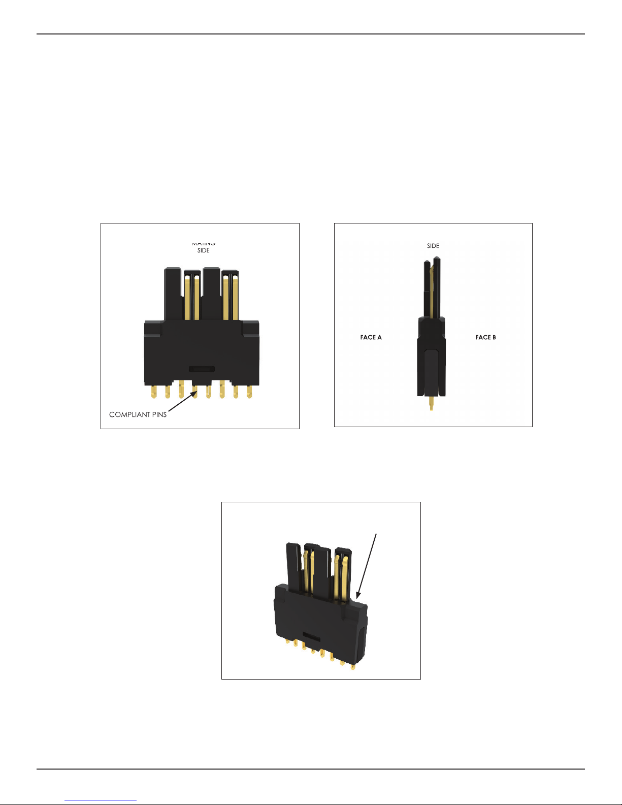
VTAC HSD VERTICAL HEADER INSERT PART IDENTIFICATION
PART # 610 151 107
This section will point out features designed to help determine the proper orientation of the VTAC HSD Vertical Header Insert as well as
its distinguishing features. The mating side of the VTAC HSD Vertical Header Insert is opposite the compliant pins as shown in Figure A.
The faces of the contact are symmetrical. The rst pin location can either be Pin 1 or Pin 8 (Figure B).
The compliant pins are used to mount the insert to the PCB with use of insertion tool # 910 112 133 (Figure C).
FRONT
MATING
SIDE
COMPLIANT PINS
Figure A. Identifying key features of the insert.
SIDE
MATING
SIDE
FACE A FACE B
Figure B. Both faces of the insert are symmetrical.
First pin location can be Pin 1 or Pin 8.
RECESSED SHOULDER
FOR INSERTION TOOL
9-1 For the most current information available, visit vpc.com
Figure C. Shoulders of insert are recessed for
insertion tool use.
1/9/19

VTAC HSD USER MANUAL: SECTION 10 VIRGINIA PANEL CORPORATION
VTAC HSD VERTICAL INSERT PCB INSTALLATION
INSTRUCTIONS FOR 90 SERIES MODULES
PART # 610 151 107
TOOLS REQUIRED
VTAC HSD Vertical Header Insert Installation Tool, Part # 910 112 133
INSERT INSTALLATION INSTRUCTIONS
1. The insertion tool is a two-piece assembly, comprised of a base and a top. Orient the assembly so that it matches Figure A.
2. Remove the top from its base. Notice the alignment pins on either side of the base. These alignment pins will be later used to
locate the PCB and the base (Figure B).
3. Load the desired number of inserts into the base as shown. Position the inserts so that the mating-side of the inserts are
oriented towards the base and the compliant pins are oriented towards the top (Figure C).
TOP
BASE
Figure A. Proper orientation of part # 910 112 133. Figure B. Remove the top of the insertion tool from its base.
ALIGNMENT
PINS
ENSURE SIDES OF
INSERT(S) ARE FULLY
SEATED
Figure C. Load the desired number of inserts into the base.
10-1 For the most current information available, visit vpc.com
Figure D. Ensure that the edges of the insert are fully
seated in the base of the insertion tool.
1/9/19

VTAC HSD USER MANUAL: SECTION 10 VIRGINIA PANEL CORPORATION
VTAC HSD VERTICAL INSERT PCB INSTALLATION
INSTRUCTIONS FOR 90 SERIES MODULES
PART # 610 151 107
INSERT INSTALLATION INSTRUCTIONS (CONT’D)
4. To use the vertical header insertion tool, the PCB must be designed to accept the alignment pins of the insertion tool. The distance
between these two alignment holes is identi ed on the drawing of part # 610 151 107.
5. With the tool’s top removed from its base, insert the alignment pins into the alignment holes of the PCB (Figure A).
6. Ensure that the compliant pins of the insert align with the plated thru-holes on the PCB board. For info on the spacing of these holes,
consult the drawing for part # 610 151 107 (Figure B).
7. With the base and PCB together, place the top on to the base of the insertion tool (Figure C).
8. Press the top insertion tool onto the base, pushing the compliant pins of the insert into the PCB. Do not over press. Remove the PCB
from the tool, and verify the installation of each insert in the PCB is correct. The insert should be ush to the PCB with a gap of no more
than .004” [.10 mm].
NOTE: Each insert requires 10 lbs [4.54 kg] of force to create a gas-tight seal when installed. Inserts should not be removed once
in place. Visually inspect the pin side of the PCB to ensure proper pin insertion with the PCB.
ALIGNMENT HOLES FOR
THE ALIGNMENT PINS OF
INSERTION TOOL
Figure A. The PCB should have alignment holes to
accept the alignment pins of the insertion tool.
PRESS-FIT TAILS OF INSERT
SHOULD ALIGN WITH
THRU HOLES
Figure B. Compliant pins align with the thru-holes of the PCB.
10-2 For the most current information available, visit vpc.com
Figure D. Finished inserts installed properly on a PCB.Figure C. Insertion tool is ready to press.
1/9/19

VTAC HSD USER MANUAL: SECTION 10 VIRGINIA PANEL CORPORATION
TROUBLESHOOTING
ITA frame is not lined up when in the process of engagement with receiver
This may indicate that the ITA is out of alignment or that a module is not mating with its intended mate.
• Remove and inspect the ITA for proper alignment.
• Check for foreign objects/tools that may impede engagement.
• Inspect the matching of modules - Signal ITA module to mate with signal receiver module, etc.
Forceful engagement of the Receiver and the ITA
will result in serious damage to multiple par ts of the
system (modules, Receiver, ITA and contacts)!
11-1 For the most current information available, visit vpc.com
1/9/19

VTAC HSD USER MANUAL: SECTION 10 VIRGINIA PANEL CORPORATION
Product Performance Specications
1. Scope
1.1. Content
This specication covers the performance, tests and quality requirements for the VTAC HSD insert
and connector system. The VTAC HSD insert is a separable electrical connection device utilizing 8
contacts housed within a hermaphroditic protective shroud. The individual inserts are to be used with
connector modules with .125 inch centerline spacing.
1.2. Qualication Testing
All inspections shall be performed using applicable inspection plans and product drawings. Upon
completion of qualication testing, this specication will be assigned a number and be classied as a
Product Qualication Report, which will be identied in section 2.
2. Applicable Documents
2.1. Content
The following documents form a part of this specication to the extent specied herein. Unless other-
wise specied, the latest edition of the document applies. In the event of a conict between requirements of this specication and product drawing, product drawing will take precedence. In the event
of a conict between requirements of this specication and referenced documents, this specication
shall take precedence.
2.2. Documents
A. EIA Standards
• EIA 364-5
• EIA 364-06
• EIA 364-13
• EIA 364-20
• EIA 364-21
• EIA 364-29
• EIA 364-70
• EIA 364-108
• AMS 2422
B. Product Drawings for the following part numbers
Housings
• 510170101
• 510171101
Contacts
• 610151101
3. Requirements
3.1. Design and Construction Product shall be of design, construction and physical dimensions specied
on applicable product drawings.
3.2. Materials
A. Contacts
• Beryllium Copper
B. Insert Shroud
• 30% Glass Filled LCP
C. Potting Compound
• OM 678
D. Housings
• Zamak 3
12-1 For the most current information available, visit vpc.com
1/9/19

VTAC HSD USER MANUAL: SECTION 10 VIRGINIA PANEL CORPORATION
Product Performance Specications
3.3. Ratings
A. Voltage
• 600 Volt Max. DC or Peak AC, use of wire M22759/11
B. Temperature
• -40°C to 125°C
3.4. Performance and Test Description Product is designed to meet electrical, mechanical, and
environmental requirements specied in Table 3 1. Unless otherwise specied, all tests should
be performed at free air, room temperature, and ambient environmental conditions.
3.5. Test Requirements and Procedures Summary
Table 3.1: Test requirements and procedure summary.
Category Test Description Requirement Procedure
Preliminary Examination of Product
Contact Resistance 30 mΩ EIA-364-06
Insulation Resistance 1000 MΩ minimum
Dielectric Withstanding Voltage
Electrical
Cross Talk
Impedance 100Ω ±10Ω Per Differential Pair
Insertion Loss -1dB to 6.25 GHz
Durability See test sequence: Table 3-2
Retention Force: Receiver
Retention Force: ITA Contact
Insertion Force: Receiver
Mechanical
1
Shall meet visual requirement, show no physical damage and shall meet requirement of additional tests as specied in Test
Sequence in Table 3.2.
Insertion Force: ITA Contact
Contact
Contact
Mating Force 0.75 lbf Max per insert
Un-mating Force ≤ 1 lbf per insert
Meets requirements of product
drawing
1050 VDC test voltage at sea
-30dB to 6.25 GHz
-40dB to 6.25 GHz
Contact shall not dislodge from
Force to insert contacts into
module ≤ 1.5 lbf
1
level
module
Visual, dimensional, and
functional examination per
applicable quality inspection
plan
EIA-364-21: Test between
adjacent contacts assembled in
housing at 500VDC
EIA-364-20: Test between
adjacent contacts at 0.5 mA
Cross talk between adjacent
differential pair within the same
insert
Cross talk between differential
pair in adjacent inserts
EIA-364-09: Mate and un-mate
sample for 10,000 cycles
EIA-364-29: Apply axial load of 5
lbs to contact
EIA-364-05
EIA-364-13: Measure force
necessary to mate samples at a
normal rate of engagement of
the ITA
EIA-364-13: Measure force
necessary to un-mate samples at
a normal rate of disengagement
of the ITA
12-2 For the most current information available, visit vpc.com
1/9/19

VTAC HSD USER MANUAL: SECTION 10 VIRGINIA PANEL CORPORATION
Product Performance Specications
3.6. Product Qualication and Requalication Test Sequence
Table 3.2: Test Sequence
Test or Examination
Characteristic Impedance 2,11
Contact Resistance 4,10
Cross Talk Between Pairs
(Adjacent Inserts)
Cross Talk Between Pairs
(Same Insert)
Dielectric Withstanding Voltage 5,11
Durability 8,15 7
Examination of Product 1,16 1,13 1
Insert Insertion Force 2
Insert Retention 3
Insertion Loss 3,12
Insulation Resistance 6,12
Mating Force 6,9 2,8
Un-mating Force 7,10 3,9
1 2 3
4,13
5,14
Test Group
Numbers indicate the sequence in which the tests are performed. For test group sample selection see 4.1.
3.7. Contact Resistance Measurement Setup.
Figure 1: Contact resistance measurement setup.
12- 3 For the most current information available, visit vpc.com
1/9/19

VTAC HSD USER MANUAL: SECTION 10 VIRGINIA PANEL CORPORATION
Product Performance Specications
3.8. Insertion Loss
Figure 2: Insertion loss SFP+ cables de-embedded at 0 cycles and 10,000 cycles.
3.9. Return Loss
Figure 3: Return loss comparison between SFP+ cable only and SFP+ cable with terminated to VTAC inserts at 0 cycles and 10,000
cycles.
12- 4 For the most current information available, visit vpc.com
1/9/19

VTAC HSD USER MANUAL: SECTION 10 VIRGINIA PANEL CORPORATION
Product Performance Specications
3.10. Crosstalk
Between Differential Pairs Within the Same Insert.
Figure 4: Crosstalk between two differential pairs within the same VTAC insert at 0 cycles and 10,000 cycles. The crosstalk
between the two differential pairs within the SFP+ cable without VTAC is shown for reference.
Between Vertically Adjacent Differential Pairs
Figure 5: Crosstalk between vertically adjacent differential pairs in two VTAC inserts at 0 cycles and 10,000 cycles. The crosstalk
between the two differential pairs within the SFP+ cable without VTAC is shown for reference.
Between Diagonally Adjacent Differential Pairs
Figure 6: Crosstalk between diagonally adjacent differential pairs in two VTAC inserts at 0 cycles and 10,000 cycles. The crosstalk
between the two differential pairs within the SFP+ cable without VTAC is shown for reference.
12- 5 For the most current information available, visit vpc.com
1/9/19

VTAC HSD USER MANUAL: SECTION 10 VIRGINIA PANEL CORPORATION
Product Performance Specications
4. Quality Assurance Provisions
4.1. Qualication Testing
4.1.1. Sample Selection
Samples shall be prepared in accordance with applicable instruction sheets and shall be selected at random from current
production.
4.1.2. Test Sequence
Qualication inspection shall be veried by testing samples as specied in Table 3 2.
4.2. Requalication Testing
If changes signicantly affecting form, t or function are made to product or manufacturing process, product assurance shall
coordinate requalication testing, consisting of all or part of original testing sequence as determined by development/product
and reliability/quality engineering.
4.3. Acceptance
Acceptance is based on verication that product meets requirements of Table 3 1. Failures attributed to equipment, test set-up
or operator deciencies shall not disqualify product. When product failure occurs, corrective action shall be taken and samples
resubmitted for qua lication. Testing to conrm corrective action is required before resubmittal.
4.4. Quality Conformance Inspection
A Certicate of Conformance (C of C) dimensional inspection must be completed for all samples prior to Qualication testing.
The applicable quality inspection plan will specify sampling acceptable quality level to be used. Dimensional and functional
requirements shall be in accordance with applicable product drawing and this specication.
12- 6 For the most current information available, visit vpc.com
1/9/19
 Loading...