

Page 1

ICON USER’S MANUAL
TABLE OF CONTENTS
SECTION 1 ICON PART IDENTIFICATION
SECTION 2 ICON RECEIVER & ITA ENGAGEMENT & DISENGAGEMENT
SECTION 3 ICON RECEIVER MOUNTING
SECTION 4 ICON ITA COVER REMOVAL AND INSTALLATION
SECTION 5 ICON CABLE CLAMP REMOVAL & INSTALLATION
SECTION 6 ICON MODULE INSTALLATION AND REMOVAL
SECTION 7 ICON ACCESSORIES
SECTION 8 PCB LAYOUT, ASSEMBLY AND MOUNTING
SECTION 9 TROUBLESHOOTING
Please note that any printed or downloaded User Manuals or Procedure Sheets may not reflect the
most current revisions. The information contained in these materials is subject to change.
For the most current information available, visit www.vpc.com.
6/7/18
Page 2
ICON USER’S MANUAL: SECTION 1 VIRGINIA PANEL CORPORATION
iCON RECEIVER PART IDENTIFICATION
PART # 310 123 XXX
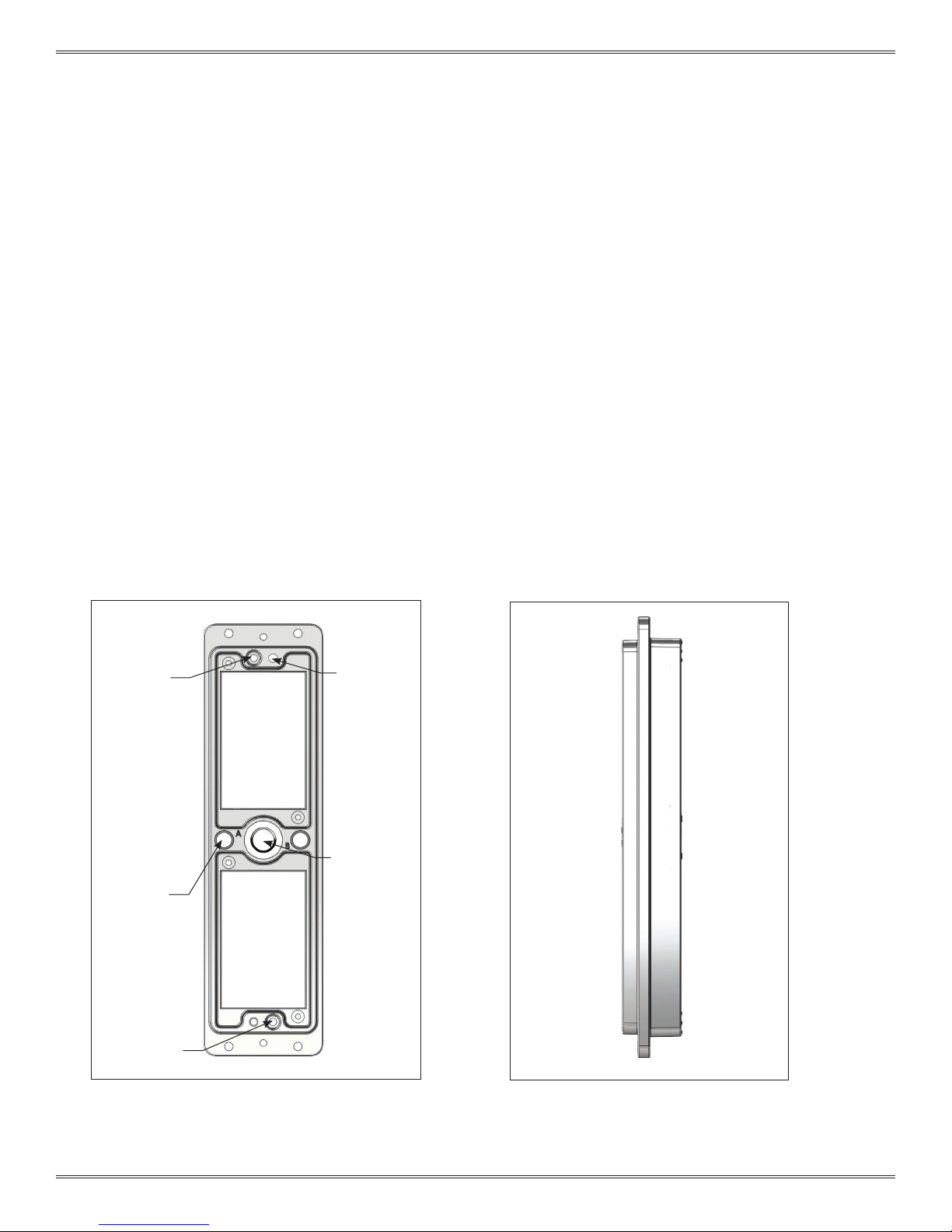
Figure A points out distinguishing features of the iCon receiver so that the top and
bottom can be identied. Features to look for are the alpha keying receptacle on
the top side and the numeric keying receptacle on the bottom. By holding the iCon
receiver, the top can be determined by holding it so the letters and numbers are
readable.
The front and rear of the iCon receiver are shown in Figure B. The front has a polarizing
feature which prevents the ITA and receiver from being engaged in the incorrect
orientation. The front of the iCon receiver can be identied as the side with the
latching feature.
The front side mates with the iCon ITA. Wires exit the iCon receiver from the rear side.
Top
Alpha Keying
Receptacle
Guide Pin
Receptacle
Numeric Keying
Receptacle
Bottom
Figure A. iCon receiver front view.
Polarizing
Feature
Receptacle
Locking
Mechanism
Receptacle
Rear
Mating
Side
Figure B. iCon receiver side view.
Front
Wiring
Side
1-1 For the most current information available, visit www.vpc.com
6/7/18
Page 3

ICON USER’S MANUAL: SECTION 1 VIRGINIA PANEL CORPORATION
iCON ITA PART IDENTIFICATION
PART # 410 123 XXX
Figure A points out distinguishing features of the iCon ITA so that the top and bottom
can be identied. Features to look for are the alpha keying receptacle on the top
side and the numeric keying receptacle on the bottom. By holding the iCon ITA, the
top can be determined by holding it so the letters and numbers are readable.
The front and rear of the iCon ITA are easily distinguished as shown in Figure B. The
front has protruding guide pins, a locking mechanism, and the rear has the knob.
The front side mates with the iCon receiver. The front has a polarizing feature which
prevents the ITA and receiver from being engaged in the incorrect orientation. Wires
exit the iCon ITA through the 30° cable clamp exit.
Top
Alpha Keying
Receptacle
Guide Pin
Numeric Keying
Receptacle
Bottom
Figure A. iCon ITA front view.
Polarizing
Feature
Locking
Mechanism
Front
Mating
Side
Figure B. iCon ITA side view.
Rear
Wiring
Side
Cable Clamp with
30° Cable Exit
1-2 For the most current information available, visit www.vpc.com
6/7/18
Page 4
ICON USER’S MANUAL: SECTION 2 VIRGINIA PANEL CORPORATION
ICON RECEIVER & ITA ENGAGEMENT & DISENGAGEMENT
RECEIVER • PART # 310 123 XXX, 310 124 XXX
ITA • PART # 410 123 XXX, 410 124 XXX
ENGAGEMENT INSTRUCTIONS
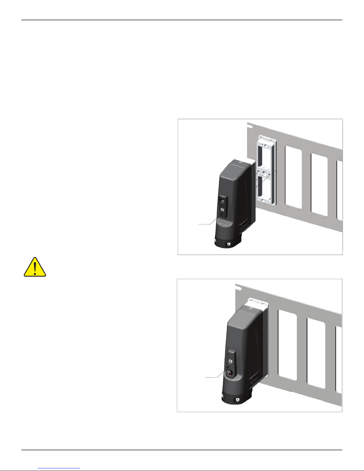
1. Turn the engagement handle to the open position as
shown in Figure A.
2. Align the dowel pins and push the ITA onto the
receiver. There will be about a 0.200″ gap.
NOTE: The iCon connector is polarized; the ITA will
not align if it is upside down.
3. Rotate the handle 180º clockwise (Figure B).
NOTE: For optimum performance and system longevity,
distribute the load evenly.
ENGAGEMENT INSTRUCTIONS
1. Turn the engagement handle to the open position.
2. Remove the ITA.
MAXIMUM CONTACT MATING FORCE
SHOULD NOT EXCEED 100 LBS.
ENGAGEMENT
HANDLE
OPEN
Figure A. When the engagement handle is open it wi ll reveal the text
“OPEN” and the two raised circles will align.
ENGAGEMENT
HANDLE
CLOSED
2-1 For the most current information available, visit www.vpc.com
Figure B. When the engagement handle is engaged, the raised
triangles will align.
6/7/18
Page 5

ICON USER’S MANUAL: SECTION 3 VIRGINIA PANEL CORPORATION
(SUPPLIED WITH 4X, 2-56 SCREWS,
ICON RECEIVER MOUNTING
PART # 310 123 101
Dimensions shown: [millimeters]
inches
5
SEE TABLE 1 FOR MINIMUM DISTANCE OF SUBSEQUENT SIDE BY SIDE CUTOUTS.
TOOLS REQUIRED
Phillips Head Screwdriver
MOUNTING INSTRUCTIONS
1. Prepare the mounting surface using the dimensions
provided in Figure A.
2. Attach the iCon receiver to the panel with the provided
2-56 Phillips head screws and nuts (Figure B). Torque
screws to 2 in-lbs [0.23 Nm].
NOTE: If the mounting surface is thicker than 0.125” [3.18
mm], longer screws may be needed.
NOTE: If the mounting surface has threaded holes, the
nuts will not be needed.
NOTE: M2.5 hardware can be used in place of the
provided 2-56 hardware.
22.86
.90
3.68
.15
PART NUMBER
410123101
410123102
410123106
410123111
410123116
410123122
6.99
.28
129.54
5.10
136.91
5.39
36.83
1.45
TABLE 1
DESCRIPTION
ITA, iCon
ITA, iCon, EMI-Shielded
ITA, iCon, with Large Cable Clamp
ITA, iCon, with Threaded Coupling
ITA, iCon, with Large Cable Clamp,
ITA, iCon with Oversized Backshell
Adapter
with EMI Housing and Handle
RECEIVER CUTOUT
SPACING
1.75 [44.45]
2.20 [55.88]
2.20 [55.88]
2.20 [55.88]
2.20 [55.88]
2.20 [55.88]
RECOMMENDED PANEL
5.
CUTOUT
TOLERANCES ARE:
.XX =
.XXX =
UNLESS OTHERWISE SPECIFIED
.01[.25]
.005[.13]
3-1 For the most current information available, visit www.vpc.com.
4.06
R
.16
MAX TYP.
FOR MOUNTING USE
[2.79].11 THRU HOLE,
2-56 OR M2.5 METRIC
TAPPED HOLE
Figure A. Recommended panel cutout.
Figure B. If you prefer metric hardware, you can replace
the supplied 2-56 screws with M2.5 ha rdware.
6/7/18
Page 6
ICON USER’S MANUAL: SECTION 4 VIRGINIA PANEL CORPORATION
ICON ITA COVER REMOVAL
PART # 410 123 XXX
The iCon ITA is designed with a removable cover to allow
the test technician access to probe signal points while
troubleshooting the test set up.
TOOLS REQUIRED
Flat Head Screwdriver
Phillips Head Screwdriver
COVER REMOVAL INSTRUCTIONS
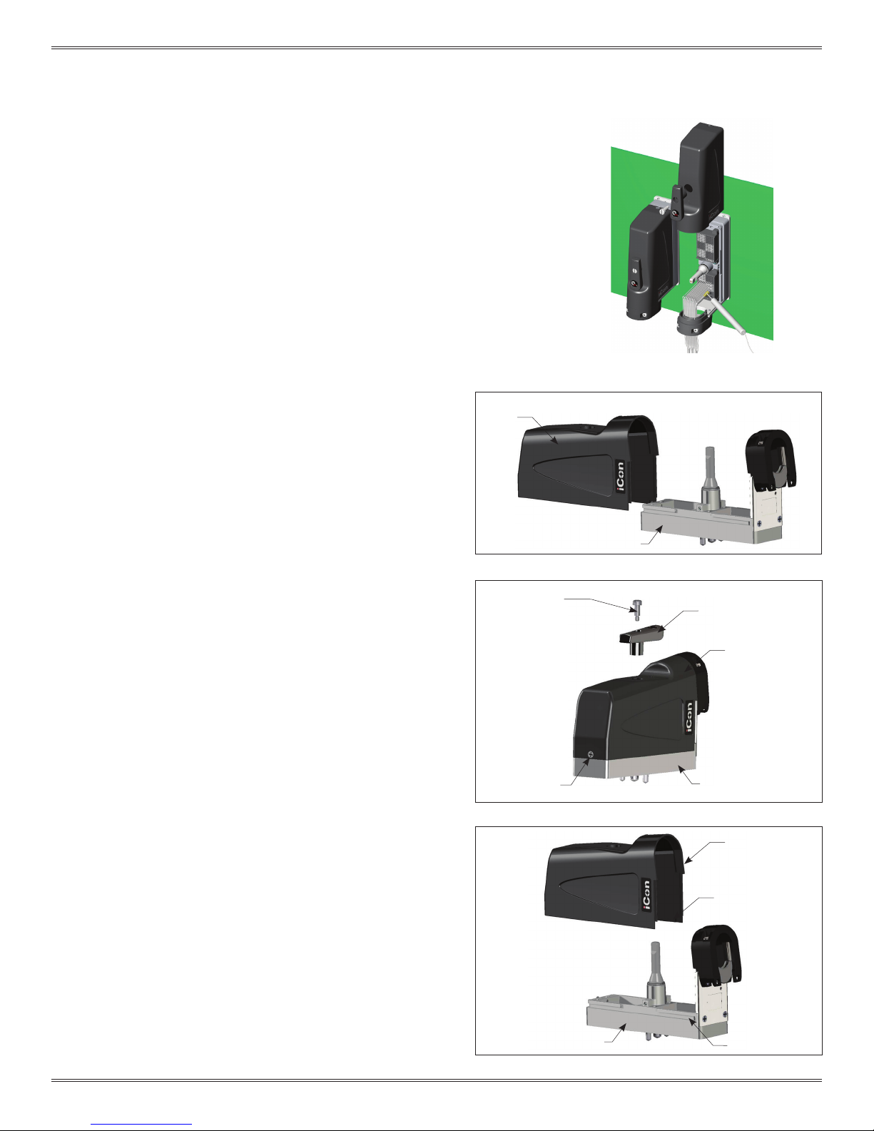
There are two options for removing the cover:
OPTION A: Slide the cover straight up the ITA frame (Figure A).
Option A requires 4.75″ of vertical space above the iCon.
REMOVABLE
COVER
OPTION B: Slide the cover halfway up the ITA frame then lift away
from the frame. This can be used if other components need to be
mounted above the iCon. Option B requires 1.64″ of vertical space
above the iCon.
OPTION A
1. Using a at head screwdriver remove the shoulder screw
located on the top of the removable cover (Figure B).
2. Remove the engagement handle by pulling it upward.
3. Loosen the captive screw with a Phillips head screwdriver
(Figure B).
4. Slide the cover off (Figure A).
OPTION B
1. Using a at head screwdriver remove the shoulder screw
located on the top of the removable cover (Figure B).
2. Remove engagement handle by pulling it upward.
3. Loosen the captive screw with a Phillips head screwdriver
(Figure B).
4. Slide the cover up until the cover notch within the cover aligns
with the notch on the ITA frame (Figure C).
Figure A.
Figure B.
ITA FRAME
SLOTTED SHOULDER
SCREW
CAPTIVE
SCREW
ENGAGEMENT
HANDLE
REMOVABLE
COVER
ITA FRAME
REMOVABLE
COVER
COVER NOTCH
5. With the notches aligned lift the cover up to remove it.
4-1 For the most current information available, visit www.vpc.com.
Figure C.
ITA FRAME
NOTCH AREA
6/7/18
Page 7
ICON USER’S MANUAL: SECTION 4 VIRGINIA PANEL CORPORATION
SCALE 3 : 1
SCALE 3 : 1
ICON ITA COVER INSTALLATION
PART # 410 123 XXX
TOOLS REQUIRED
Flat Head Screwdriver
Phillips Head Screwdriver
COVER INSTALLATION INSTRUCTIONS
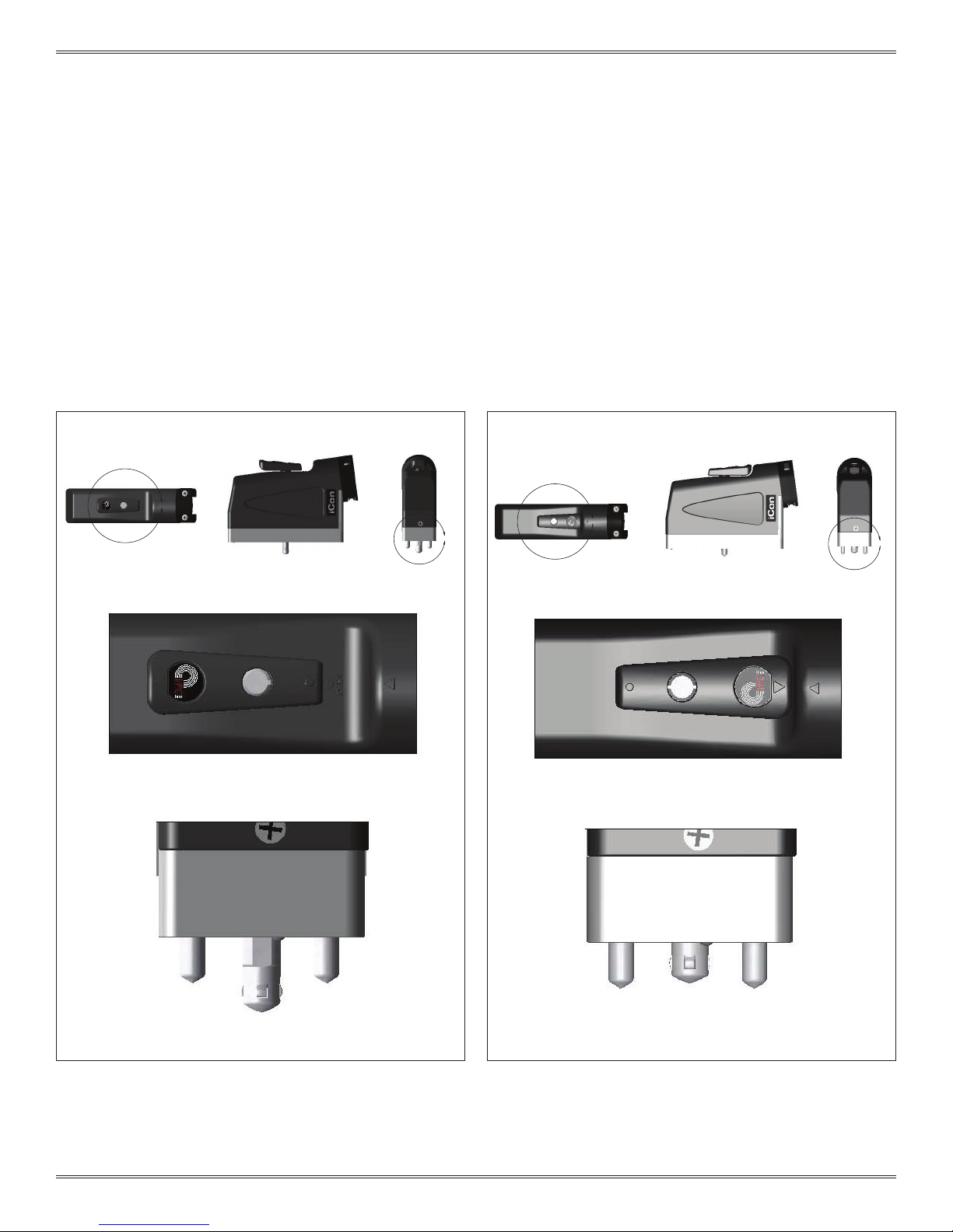
There are two options for installing the cover:
OPTION A: Installing the cover while the iCon ITA is disengaged from the
receiver or the ITA is in the disengaged position (Figure A).
A
B
DETAIL A
SCALE 2 : 1
OPTION B: Installing the cover while the iCon ITA is engaged to the
receiver or the ITA is in the engaged position (Figure B).
C
DETAIL C
SCALE 2 : 1
D
DETAIL B
Figure A. iCon ITA in the open position.
4-2 For the most current information available, visit www.vpc.com.
DETAIL D
Figure B. iCon ITA in the engaged position.
6/7/18
Page 8
ICON USER’S MANUAL: SECTION 4 VIRGINIA PANEL CORPORATION
SHOULDER SCREW
SUPPLIED 4-40
ICON ITA COVER INSTALLATION
PART # 410 123 XXX
COVER INSTALLATION INSTRUCTIONS CONTINUED
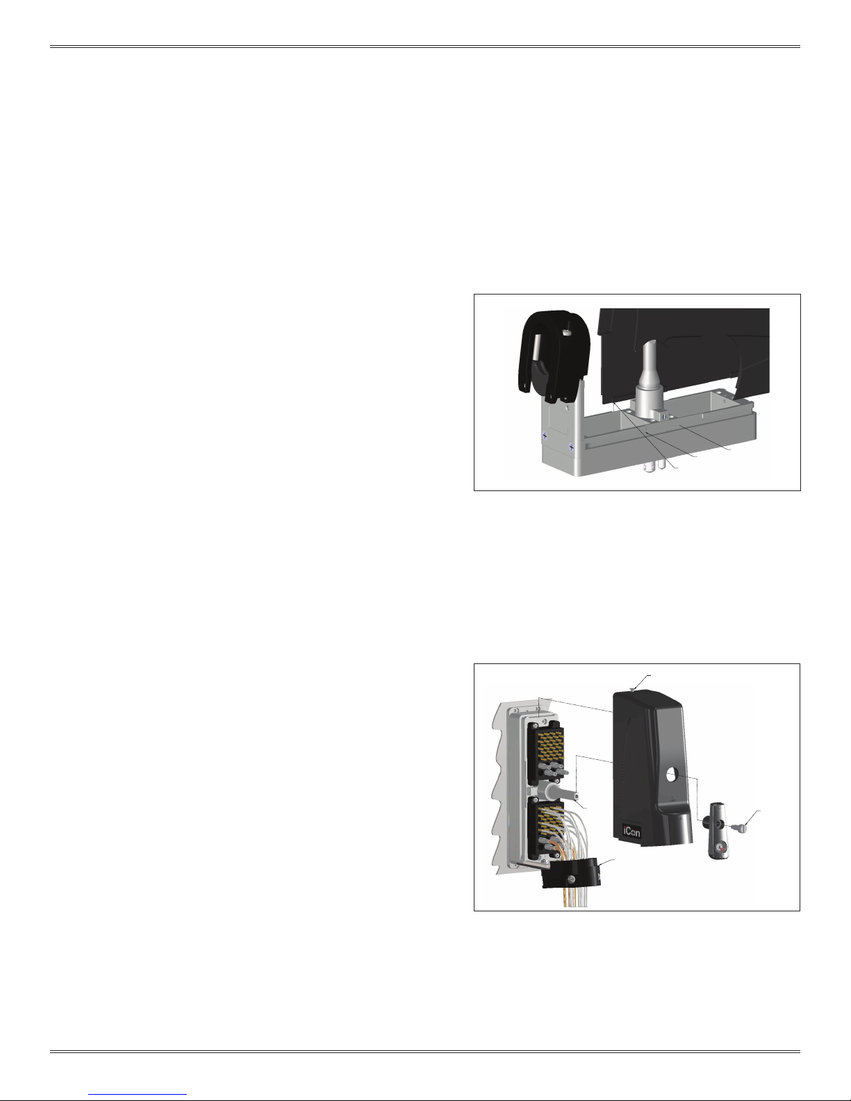
OPTION A: DISENGAGED POSITION
1. Place the cover onto the ITA as shown in Figure A. The lip will
align with the ITA groove.
2. Slide the cover onto the ITA frame until it is fully seated against
the cable clamp.
3. Place the handle (onto the shaft with the raised circles aligned.
Make sure wires are routed around the shaft and do not get
caught between the handle (Figure B) and shaft.
4. Position the supplied 6-32 shoulder screw into the handle and
tighten with a Flat Head screwdriver (Figure B).
5. Finally, tighten the captive screw at the top of the ITA securing
the cover to the ITA.
COVER LIP EDGES
Figure A. The notch area provides an option of sliding
the cover half way as explained in the “ICON ITA COVER
REMOVAL” section.
ITA GROOVE
NOTCH AREA
OPTION B: ENGAGED POSITION
1. Place the cover onto the ITA as shown in Figure A. The lip will
align with the ITA groove.
2. Slide the cover onto the ITA frame until it is fully seated against
the cable clamp.
3. Place the handle onto the shaft with the raised triangles lined up
as shown in Figure B.
4. Position the supplied 6-32 shoulder screw into the handle and
tighten with a Flat Head screwdriver (Figure B).
5. Finally, tighten the captive screw at the top of the ITA securing
the cover to the ITA.
4-3 For the most current information available, visit www.vpc.com.
FLATHEAD SCREW
SHAFT
CABLE CLAMP
Figure B. Route the wires around the shaft to avoid
damage when the handle is attached.
SUPPLIED 6-32
6/7/18
Page 9
ICON USER’S MANUAL: SECTION 5 VIRGINIA PANEL CORPORATION
ICON ITA CABLE CLAMP REMOVAL AND INSTALLATION
PART # 410 123 XXX
The iCon ITA cable clamp is designed to allow the
test technician to easily recongure or add wired
modules to the system.
TOOLS REQUIRED
Phillips Head Screwdriver
CABLE CLAMP REMOVAL INSTRUCTIONS
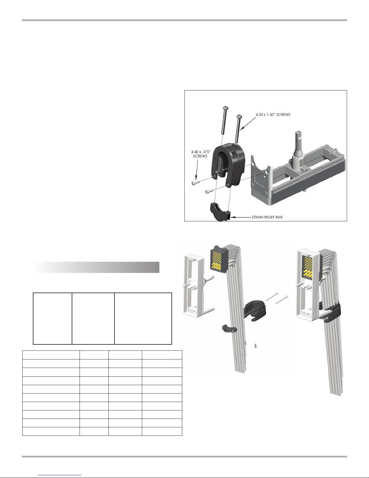
1. After removing the handle and cover, loosen the 6-32 x
1.5” screws to allow the wire(s) or cable to slide freely in
the clamp.
2. Unscrew the 4-40 x .375” screws holding the clamp
to the ITA frame (Figure A). Afterwards, if necessary,
entirely remove the 1.5” screws to allow the wire(s) or
cable to be removed.
CABLE CLAMP INSTALLATION INSTRUCTIONS
1. Place wire(s) or cables into “U” shaped clamp. Install
strain relief bar and start 1.5” screws; alternate screws
when tightening.
2. Install .375” screws to mount clamp to ITA frame. Slowly
alternate tightening the 1.5” screws until the clamp has
cinched the wire(s) or cable tightly.
NOTE: The U-shaped cable clamp is adjustable to
accommodate the amount of wires in your cable bundle.
FORMULA TO CALCULATE THE MAXIMUM
NUMBER OF WIRES IN A CABLE BUNDLE
B = 1.2 √(N
B = Wire Bundle
Diameter
2
+ N2d
1d1
N1 = Quantity of
rst wire type
N2 = Quantity of
second wire type
Nn = Quantity of
nth wire type
2
+. . . +Nnd
2
d1 = Outside Diameter
of rst wire type
d
= Outside Diameter
2
of second wire type
dn = Outside Diameter
of nth wire type
2
)
n
WIRE TYPE Ø [in] # WIRES BUNDLE Ø [in]
26AWG 16878/4 0.043 549 1.21
24AWG 16878/4 0.048 441 1.21
22AWG 16878/4 0.054 348 1.21
M27500-26ml2t08 0.114 78 1.21
M27500-24ml2t08 0.126 64 1.21
M27500-22ml2t08 0.140 52 1.21
M27500-22ml1t08 0.087 134 1.21
22AWG 16878/4 T/P 0.108 87 1.21
24AWG 16878/4 T/P 0.096 110 1.21
Figure A. The U-shape allows cables to be preterminated before
clamp installation.
NOTE: Acceptable bundle dimension must be reduced
when using sleeving and shrink tubing.
5-1 For the most current information available, visit www.vpc.com.
6/7/18
Page 10
ICON USER’S MANUAL: SECTION 5 VIRGINIA PANEL CORPORATION
RECOMMENDED SLEEVING INSTRUCTIONS
In order to prevent protective sleeving slippage for cable assemblies, VPC recommends lacing to secure the wire to sleeve
or wrapping with silicone tape. We have internal procedures to resolve these types of issues in order to provide optimal
outcomes for your system. Please contact us with any questions. Below are VPC best practices for securing protective
sleeving.
TOOLS REQUIRED
Blunt Sewing Needle
Wax Lacing Tape
Cable Sleeving
Silicone Tape (optional)
OPTIONAL CABLE SLEEVING INSTRUCTIONS
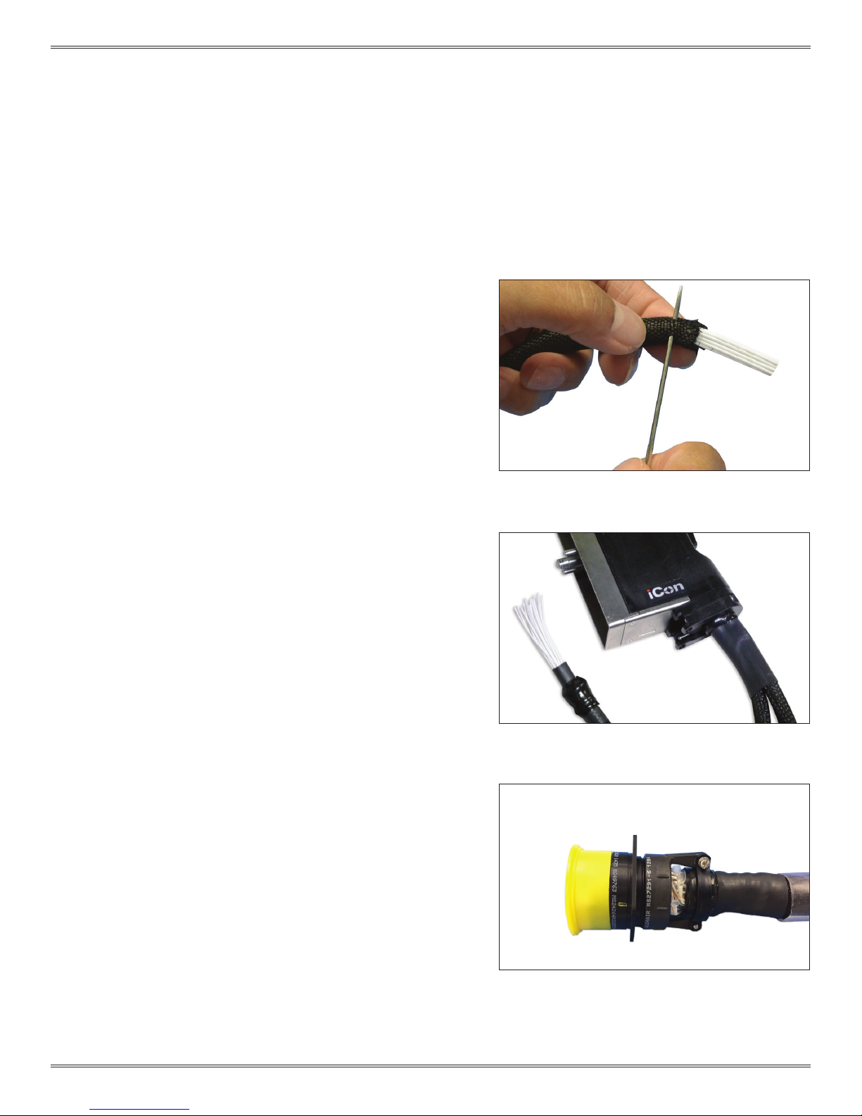
1. Fold the end of the sleeving under.
2. Sew the sleeving to the wires using lacing tape
(Figure A); using a ‘gure 8’pattern around the wires is
recommended for a better hold.
3. Use silcone tape to increase cable diameter, if necessary,
for a secure clamp (Figure B & C).
Figure A. Lacing.
4. When possible, place sleeving under the inside of the
clamp.
NOTE: The prefer red method is to place sleeving inside clamp
regardless of tape use.
Figure B. Example of silicone tape usage.
5-2 For the most current information available, visit www.vpc.com.
Figure C. Example of silicone tape on ci rcular connector.
6/7/18
Page 11
ICON USER’S MANUAL: SECTION 6 VIRGINIA PANEL CORPORATION
ICON RECEIVER MODULE INSTALLATION AND REMOVAL
PART # 310 123 XXX
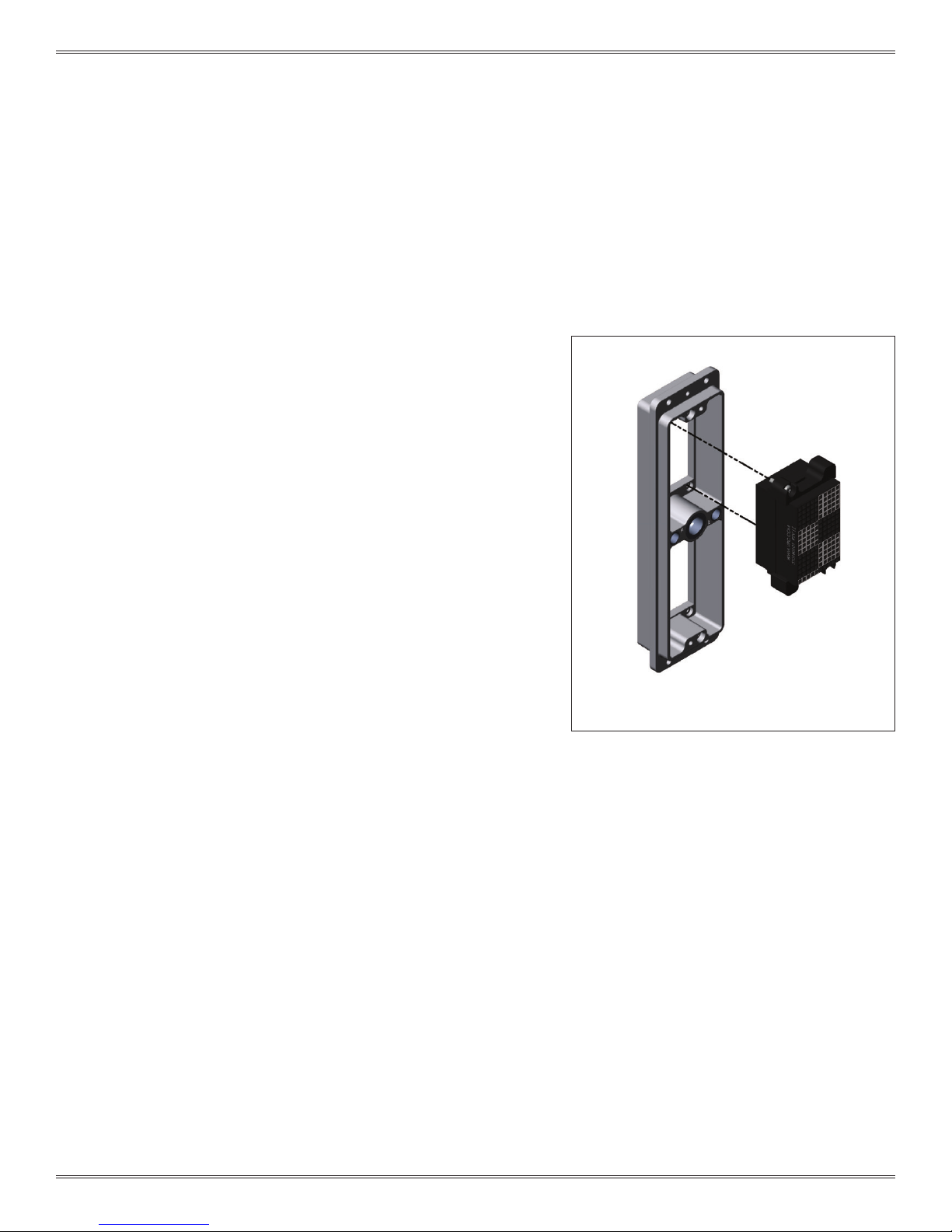
The iCon receiver is designed so the modules mount
from the rear. This allows the test technician to easily
mount wired cable assemblies without having to route
the connectors through the receiver frame.
TOOLS REQUIRED
Phillips Head Screwdriver
NOTE: If the application requires, receiver modules can be
installed in the ITA and ITA modules in the receiver (must use
receiver Part # 310 123 103). If this is done, you must be sure
to switch the contacts as well (receiver contacts in a receiver
module and ITA contacts in an ITA module). You should also use
the keying kit to prevent attempted mating to a receiver or ITA
that has a standard module orientation.
RECEIVER MODULE INSTALLATION INSTRUCTIONS
1. Place the module in the receiver until the upper and lower
module screws touch the mating holes in the frame. Install
modules such that Pin 1 is located at the top of the receiver
frame (Figure A).
2. Using a Phillips head screwdriver, tighten the top screw 1 to 2
full revolutions, while pushing lightly against the face of the
module.
3. Maintain this pressure while tightening the bottom screw 1 to
2 full revolutions.
4. Repeat this sequence until the module is seated. Torque the
screw to 1.5 in-lbs [0.16 Nm].
RECEIVER MODULE REMOVAL INSTRUCTIONS
1. To remove, loosen the top screw 1 to 2 full revolutions.
Loosen bottom screw 1 to 2 full revolutions.
2. Repeat this sequence until the module is separated from the
receiver.
NOTE: For optimum performance and system longevity,
distribute the contact load evenly throughout the module.
Figure A. The 2-56 module screws are designed with
a captive feature for loss prevention.
6-1 For the most current information available, visit www.vpc.com.
6/7/18
Page 12
ICON USER’S MANUAL: SECTION 5 VIRGINIA PANEL CORPORATION
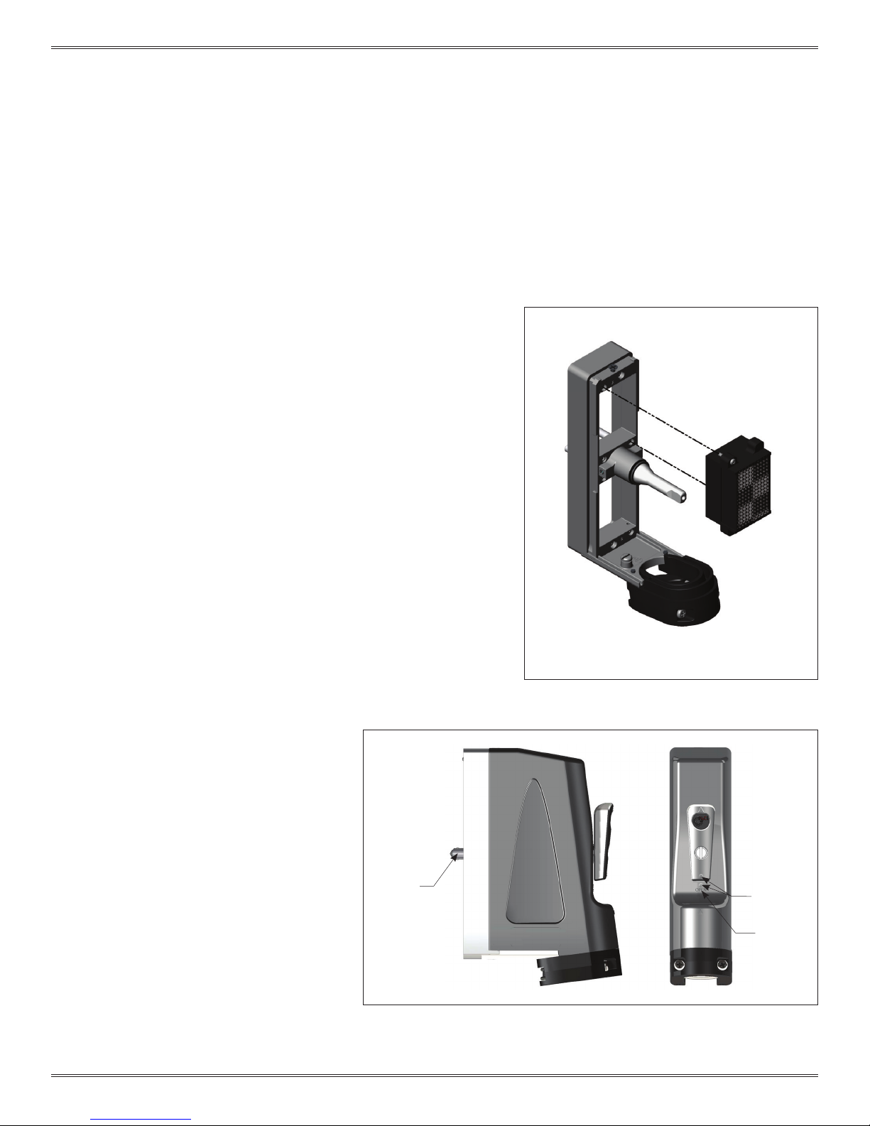
ICON ITA MODULE INSTALLATION AND REMOVAL
PART # 410 123 XXX
TOOLS REQUIRED
Phillips Head Screwdriver
NOTE: If the application requires, receiver modules can be installed in
the ITA and ITA modules in the receiver (must use receiver Part #
310 123 103). If this is done, you must be sure to switch the contacts as
well (receiver contacts in a receiver module and ITA contacts in an ITA
module). You should also use the keying kit to prevent attempted mating to a receiver or ITA that has a standard module orientation.
ITA MODULE INSTALLATION INSTRUCTIONS
1. Remove the cover. Refer to Section 4.
2. Place the module in the ITA until the upper and lower module
screws touch the mating holes in the frame. Install modules such
that Pin 1 is located at the top of the ITA frame (Figure A).
3. Using a Phillips head screwdriver, tighten the top screw 1 to 2 full
revolutions, while pushing lightly against the face of the module.
4. Maintain this pressure while tightening the bottom screw 1 to 2 full
revolutions.
5. Repeat this sequence until the module is seated. Torque the
screw to 1.5 in-lbs [0.16 Nm].
6. Reinstall the removable cover. It is important to
align the handle correctly (Figure B), or refer to
Section 4.
ITA MODULE REMOVAL INSTRUCTIONS
1. To remove, loosen the top screw 1 to 2 full
revolutions. Loosen bottom screw 1 to 2 full
revolutions.
2. Repeat this sequence until the module is
separated from the ITA.
NOTE: For optimum performance and system
longevity, distribute the contact load evenly
throughout the module.
ENGAGEMENT
MECHANISM
EXTENDED
Figure A. Make sure position 1 on the ITA module
aligns with position 1 on the receiver module.
RAISED
CIRCLE
OPEN
6-2 For the most current information available, visit www.vpc.com.
Figure B. If the engagement mechanism is extended beyond the alignment pins
the handle should be attached in the “OPEN” position. Open is indicated by
aligning the raised circles on the handle and cover and revealing the “OPEN”
text.
6/7/18
Page 13
ICON USER’S MANUAL: SECTION 7 VIRGINIA PANEL CORPORATION
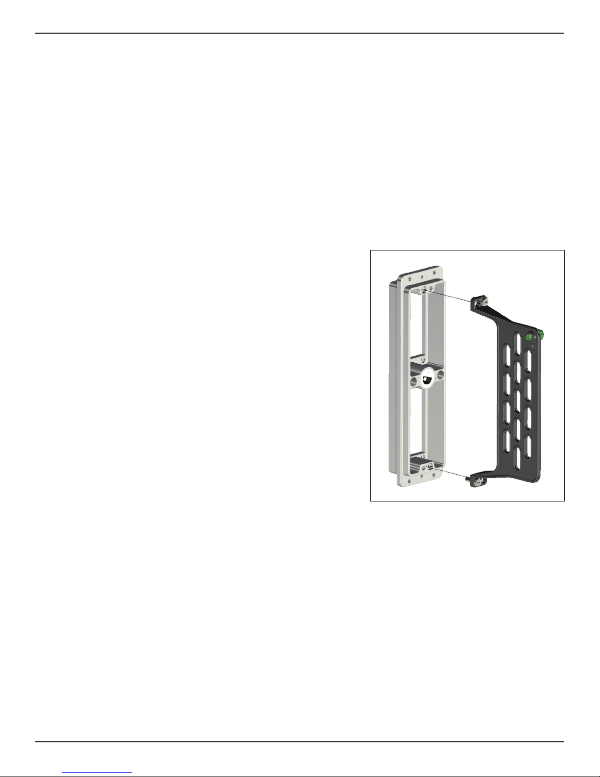
ICON RECEIVER STRAIN RELIEF ASSEMBLY
PART # 310 113 456
TOOLS REQUIRED
Phillips Head Screwdriver
ASSEMBLY INSTRUCTIONS
1. Attach the strain relief to the iCon receiver on the wiring side
of the receiver frame (Figure A).
2. Fasten the strain relief to the iCon receiver frame with the
included screws and a Phillips head screwdriver.
3. Wires should be restrained a minimum of 2 inches from the
wiring face of the module. Six wire ties are included with the
strain relief.
NOTE: If using 8AWG, 10AWG or non-exible Coaxial wire in the
center module positions, the iCon Strain Relief stand-off Kit, Part # 310
113 582, will be required.
NOTE: When using the strain relief stand-off kit, install patchcords into
module before attaching strain relief.
Figure A. Strain relief diagram showing proper
hole alignment.
7-1 For the most current information available, visit www.vpc.com.
6/7/18
Page 14
ICON USER’S MANUAL: SECTION 7 VIRGINIA PANEL CORPORATION
CENTER BOSS
CENTER BUSHING
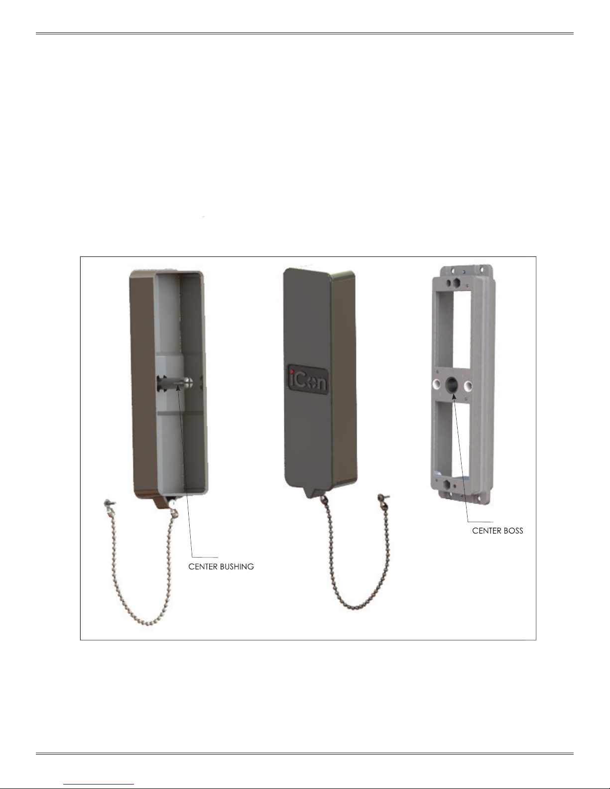
ICON RECEIVER PROTECTIVE COVER INSTALLATION
PART # 310 113 460
INSTALLATION INSTRUCTIONS
1. Align the center boss on the cover with the center bushing
on the receiver (Figure A).
2. Push the cover on ensuring that the two smaller alignment
bushings mate properly.
3. Press the cover until it seats fully against the receiver.
CENTER BUSHING
Figure A.
7-2 For the most current information available, visit www.vpc.com.
CENTER BOSS
6/7/18
Page 15
ICON USER’S MANUAL: SECTION 7 VIRGINIA PANEL CORPORATION
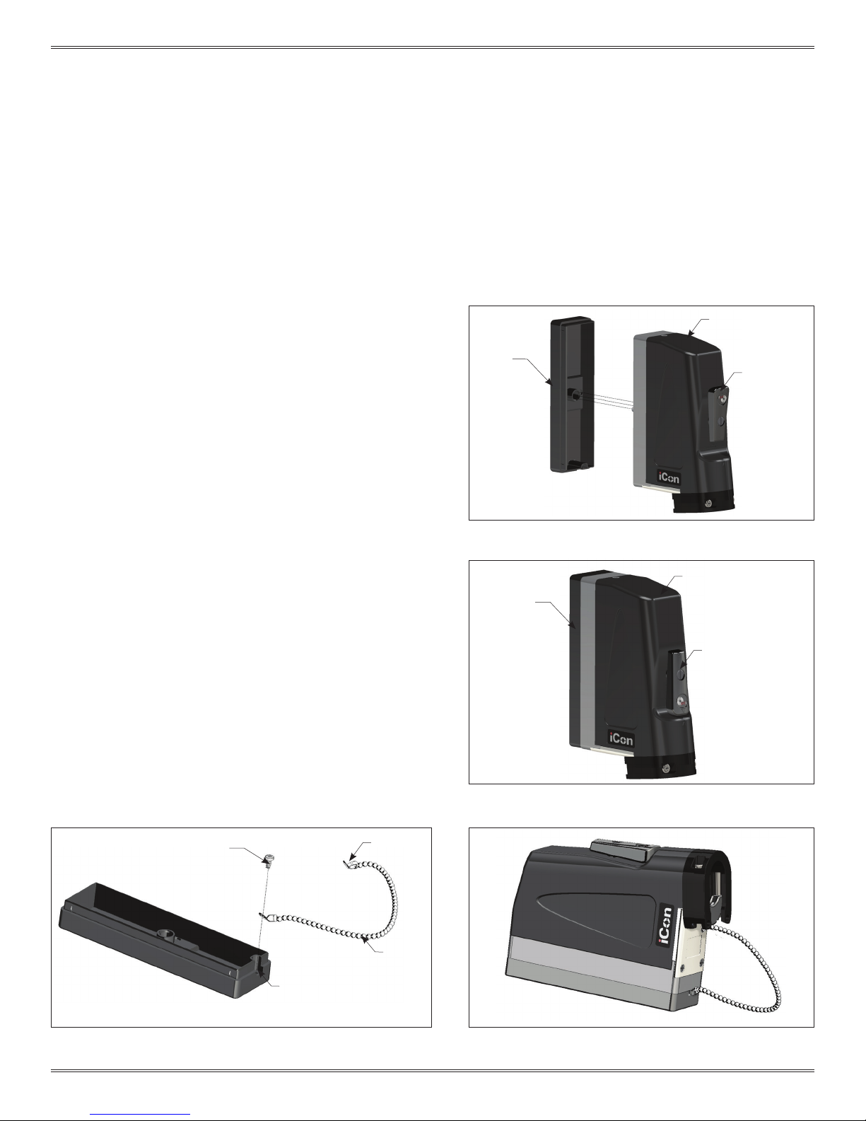
ICON ITA PROTECTIVE COVER ASSEMBLY AND INSTALLATION
PART # 410 112 750
The ITA protective cover can be mounted to
a cabinet or enclosure if a permanent storage
location for the ITA is desired.
ASSEMBLY INSTRUCTIONS
1. Move the iCon engagement handle to the open position.
2. Place the protective cover on the engagement mechanism
as shown in Figure A.
3. Turn the engagement handle to the closed position to fully
mate the iCon ITA and protective cover (Figure B).
INSTALLATION OF THE ITA PROTECTIVE COVER CHAIN
1. Attach one end of the chain to one of the supplied eyelets.
2. Attach the eyelet to the mounting hole in the protective
cover (Figure C).
3. Thread the chain through the mounting hole on the ITA base
(Figure D).
4. Attach the end of the chain to the end of the eyelet.
NOTE: A chain lanyard, protective cover, and hardware are
included with iCon ITA, part # 410 123 101.
ICON ITA
PROTECTIVE
COVER
ENGAGEMENT
HANDLE
IN OPEN
POSITION
Figure A. When the engagement handle is open, the raised
circles will align and reveal the word “OPEN.”
ICON ITA
PROTECTIVE
COVER
ENGAGEMENT
HANDLE IN
CLOSED POSITION
SUPPLIED
4-40 SCREW
CHAIN
MOUNTING
HOLE
Figure C. The provided 4-40 screw has sharp angled threads to
easily secure the lanyard to the protective cover.
7-3 For the most current information available, visit www.vpc.com.
Figure B. The triangles on the removable cover and
engagement handle align to indicate the closed position.
SUPPLIED
EYELET
SUPPLIED
CHAIN
Figure D. This end of the eyelet can be attached using the
mounting hole on the ITA.
6/7/18
Page 16
ICON USER’S MANUAL: SECTION 7 VIRGINIA PANEL CORPORATION
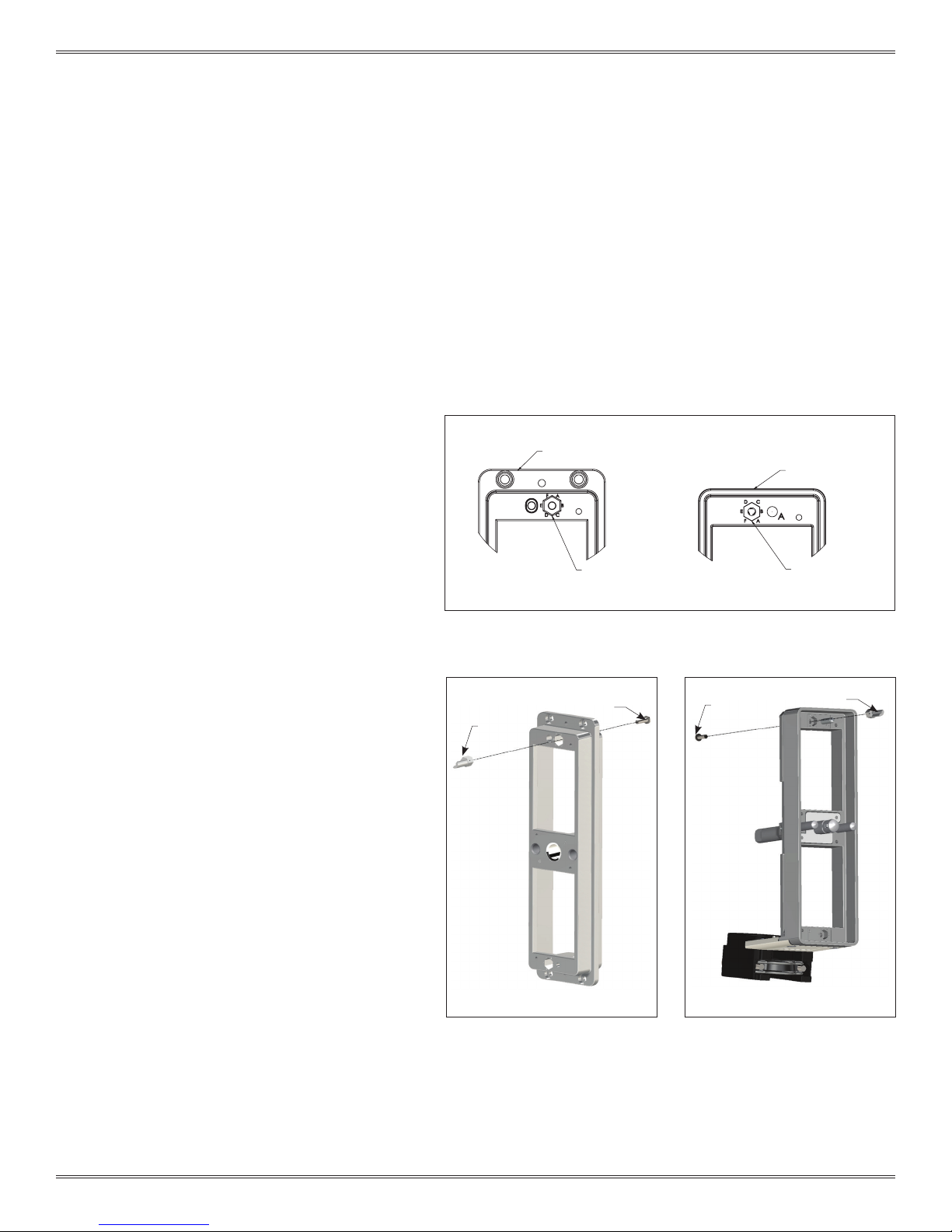
KEYING NOMENCLATURE
KEYING NOMENCLATURE
ICON RECEIVER MATING FACE
KEYING PIN KIT, RECEIVER AND ITA ASSEMBLY
PART # 310 113 461
The iSeries keying kit includes two pins and screws
which provide six different keying options. The
iCon system is designed to accept two kits which
increase the keying options to 36.
TOOLS REQUIRED
Phillips Head Screwdriver
Flat Blade Screwdriver
ASSEMBLY INSTRUCTIONS
1. Align the keying pin in the desired location. Place
the keying pin in the hexagonal opening in the iCon
receiver. Figure A is a detailed view of the keying
feature.
ICON ITA MATING FACE
2. Secure the keying pin with the 2-56 phillips head
screws (Figure B).
3. Remove the iCon ITA cover.
4. Place the other keying pin in the corresponding
location in the iCon ITA. Refer to Figure C.
5. Replace the iCon ITA cover.
Figure A. In order to mate the connector, the keying pin will be in the
same alphabetical positions in both the iCon receiver and ITA.
KEYING
PIN
KEYING
PIN
2-56
SCREW
2-56 SCREW
7-4 For the most current information available, visit www.vpc.com.
Figure B. The keying pin kit, Part #
310 113 461, includes two keying
pins and two screws.
Figure C. One keying pin kit will
allow 6 variations. By using a
second keying pin kit, you will
have 36 different variations.
6/7/18
Page 17
ICON USER’S MANUAL: SECTION 8 VIRGINIA PANEL CORPORATION
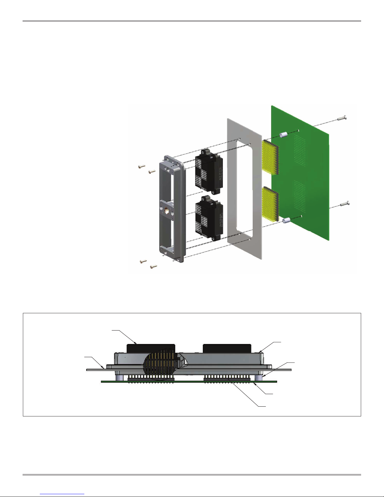
Standard .100" spacing male header
Custom mounting panel
1
Receiver module with Quadrapaddle
ICON PCB LAYOUT AND MOUNTING OVERVIEW
The iCon receiver is designed as a rack and panel
mount connector that can have a PCB attached
on the rear side. While it is capable of being
mounted directly to a PCB without an intermediary
panel, VPC recommends mounting the iCon
receiver to a panel and then mounting the PCB to
the other side of the panel using stand-offs (Figure
A). This will reduce the amount of stress the PCB
endures when the iCon is mated and un-mated.
Twin Female contacts, 510160105
Figure A.
8-1 For the most current information available, visit www.vpc.com.
iCon Receiver frame, 31012310
Threaded Stand off
(customer desired length)
Custom printed circuit board
6/7/18
Page 18
ICON USER’S MANUAL: SECTION 8 VIRGINIA PANEL CORPORATION
E
RECEIVER FRAME MOUNTING PLATE
/
0.45” [11.4 mm]
HEADER CARRIER HEIGHT
ICON PCB MOUNTING OVERVIEW
HEADER, .100 SPACING TWIN MALE SOLDERED
TO PCB CREATES A
SEPARABLE INTERFACE
ICON RECEIVER FRAM
160 PIN TWIN FEMALE ICON MODULE
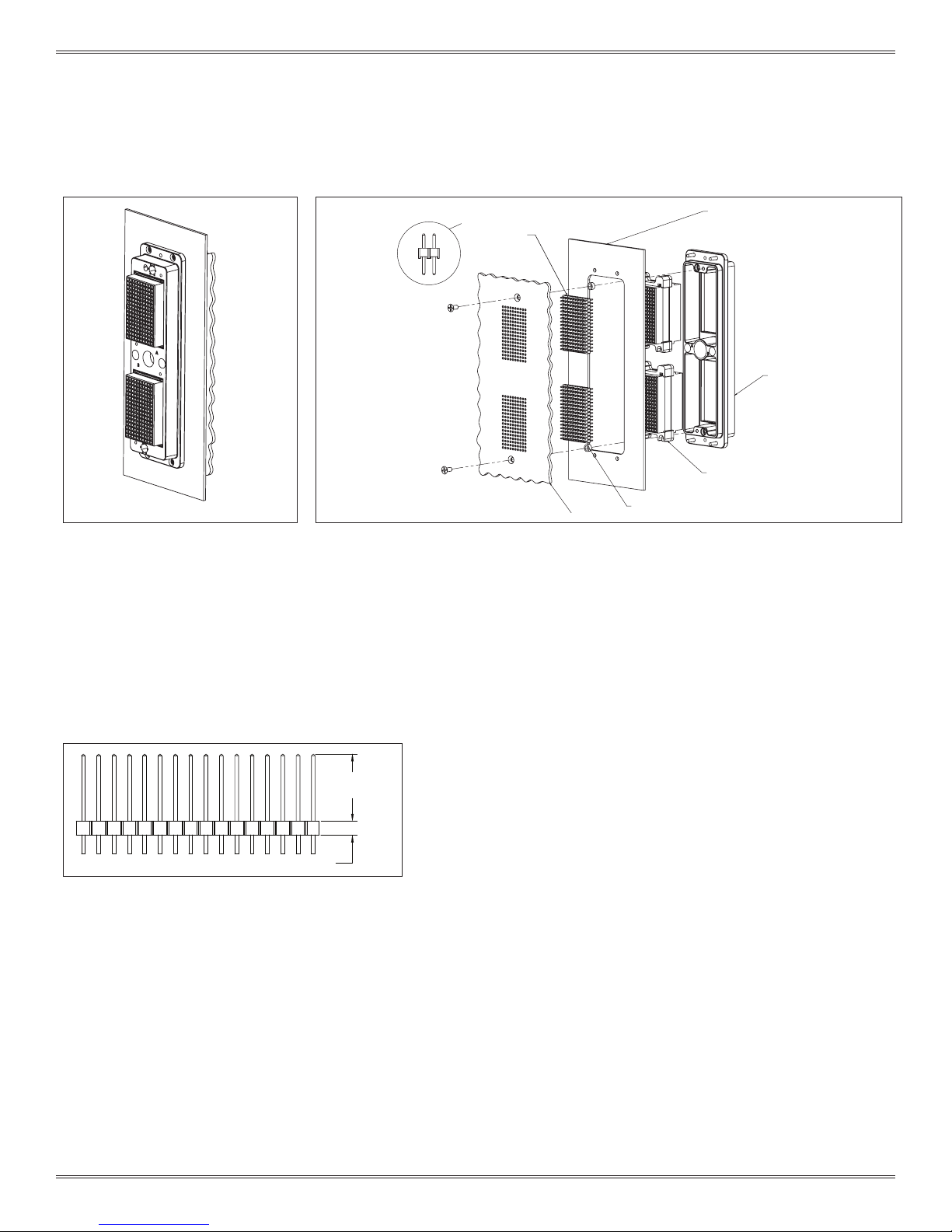
Figure B. iCon receiver with t wo
160 pin QuadraPaddle modules.
Each module is loaded with twin
female contacts, Part # 510 160 105.
Each module will accept twin male
headers connecting the female
contacts to the PCB plated thru holes.
Figure D. Twin male header.
SPACER, SAME WIDTH AS HEADER BODY TO
Figure C. A PCB can be mounted directly to the back of an iCon receiver as shown above.
Use 2 x 4-40 screws (athead shown) to mount to the Receiver frame. When using twin male
headers, spacers may be needed to prevent unwanted stress on the PCB.
NOTE: Figure D detai ls 0.22” [5.59 mm]/0.45” [11.43 mm] min/max
engagement.
0.22” [5.6 mm]
NOTE: Minimum spacer height = 0.24” + header carrier height panel thickness (if used).
Any additional height beyond this minimum must be added to
the header post limits shown in Figure D.
NOTE: Several manufacturers offer the twin male header:
Samtec, TE, MultiComp, Molex. The specic part number
required is dependant on the distance the iCon will be located
from the PCB, the thicknes s of the PCB, and the plating type
required.
8-2 For the most current information available, visit www.vpc.com.
6/7/18
Page 19
ICON USER’S MANUAL: SECTION 8 VIRGINIA PANEL CORPORATION
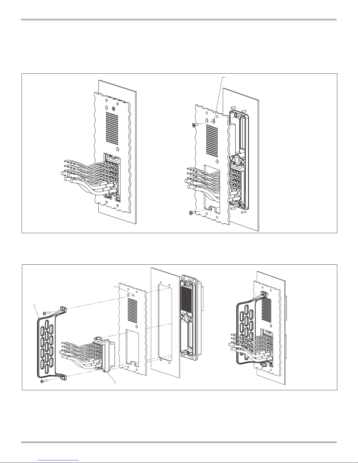
COUNTERSUNK HOLE FOR
ICON PCB MOUNTING OVERVIEW
FLATHEAD SCREW
Figure F. User can use athead screws to mount the PCB as shown. This can be done when no strain relief is required.
THRU HOLE FOR
MOUNTING THE PCB
STRAIN RELIEF PLATE
DISCRETE WIRING MODULE
Figure G. A strain relief plate, Par t # 310 113 456 can be used with a PCB as shown. To do this put thru holes on the PCB and use a 4-40
pan head screw.
8-3 For the most current information available, visit www.vpc.com.
6/7/18
Page 20
ICON USER’S MANUAL: SECTION 8 VIRGINIA PANEL CORPORATION
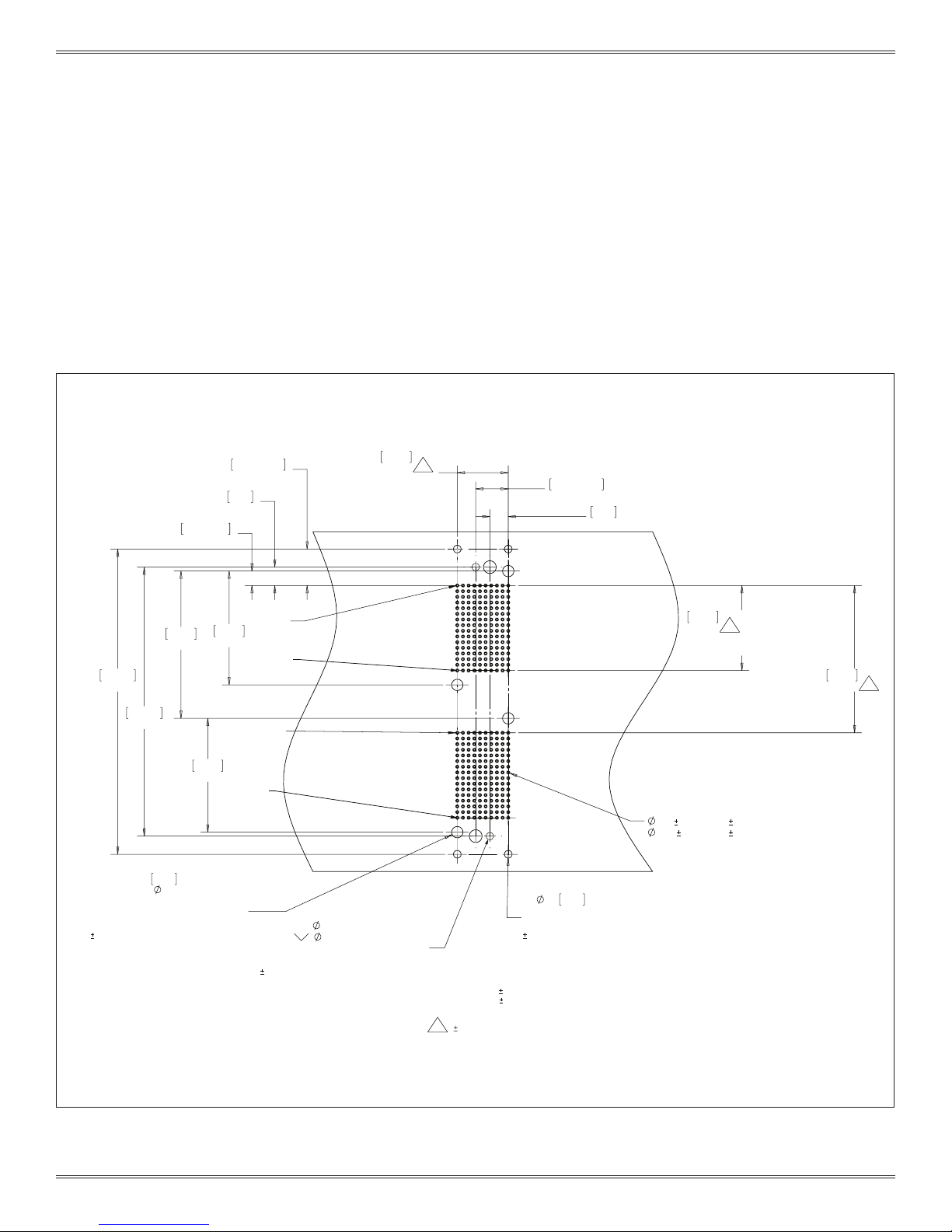
PCB LAYOUT AND MOUNTING
SIGNAL MODULE, RECEIVER, QUADRAPADDLE, ICON, 160 POSITION,
FULLY LOADED WITH TWIN FEMALE CONTACTS • PART # 510 160 105
PCB layout for the iCon Receiver, Part # 310 123 101 loaded with two 510 160 105 modules.
Thru hole and pad diameters are for VPC QuadraPaddle Adapter Contact, Part #610 138 117.
The size of these holes may be different if a header from a different manufacturer is used.
Also shown are optional clearance holes.
VPC modules/pin mount this side.
16.38±0.25
.645±.010
8.26
.325
6.48±0.25
.255±.010
51.05
2.01
51.05
2.01
PIN A16
PIN A1
PIN A16
66.04
2.60
136.91
5.39
120.65
4.750
5.08
6X
THRU
OPTIONAL CLEARANCE HOLES FOR ACCESS
TO MODULE MNTG SCREWS AND
KEYING PIN ACCESSORY SCREWS
.01 LOCATION TOLERANCE APPLIES
.20
22.86
9 EQUAL SPACES @.100
PIN A1
2X
.129 [3.26] THRU
PCB TO RECEIVER MOUNTING HOLES
USES TWO 4-40 FLATHEAD SCREWS
.005 LOCATION TOLERANCE APPLIES
.225 [5.72] X 82° FAR SIDE
.900
TYP. 2 PATTERNS
1
4X
CLEARANCE HOLES FOR
RECEIVER MOUNTING HARDWARE
.01 LOCATION TOLERANCE APPLIES
RECOMMENDED PCB LAYOUT
CONNECTOR MOUNTS THIS SIDE
TOLERANCES ARE:
.XX=
[0.25] .01
.XXX=
UNLESS OTHERWISE SPECIFIED
1
APPLIES TO PLATED THRU HOLES
[0.13] .005
.0021 LOCATION TOLERANCE
14.61±0.25
.575±.010
.14 3.43
8.26
.325
THRU
38.10
1
1.500
15 EQUAL SPACES @.100
TYP. 2 PATTERNS
66.04
1
2.600
320X
037
.003 [0.094
.054 .003 [1.37
0.08] PLATED THRU HOLE
0.08] SOLDER PAD
8-4 For the most current information available, visit www.vpc.com.
6/7/18
Page 21
ICON USER’S MANUAL: SECTION 8 VIRGINIA PANEL CORPORATION
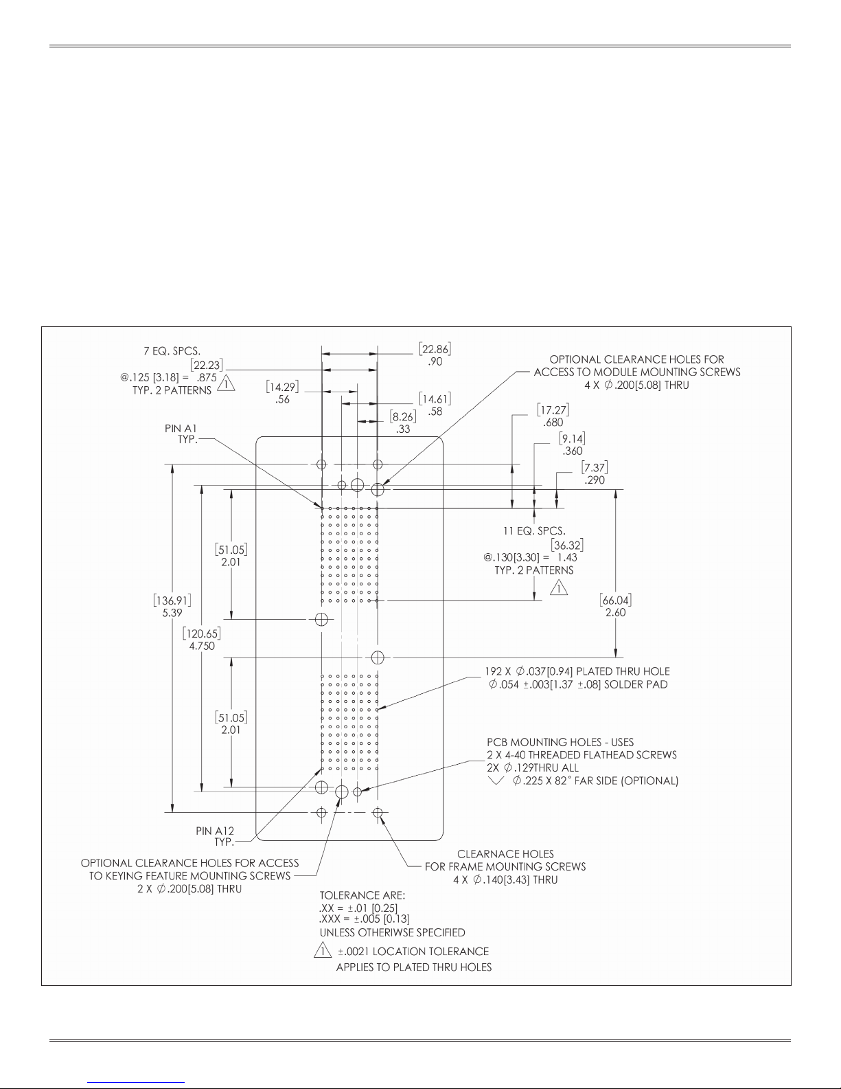
PCB LAYOUT AND MOUNTING
SINGLE MODULE, RECEIVER, TRIPADDLE, ICON, 96 POSITION,
FULLY LOADED WITH FEMALE CONTACTS • PART # 510 160 108
PCB layout for the iCon Receiver, Part # 310 123 101 loaded with two 510 160 108 modules.
Thru hole and pad diameters are for VPC TriPaddle Adapter Contact, Part #610 110 179.
The size of these holes may be different if a header from a different manufacturer is used.
Also shown are optional clearance holes.
VPC modules/pin mount this side.
8-5 For the most current information available, visit www.vpc.com.
6/7/18
Page 22
ICON USER’S MANUAL: SECTION 8 VIRGINIA PANEL CORPORATION
FOR ACCESS TO MODULE MOUNTING SCREWS
ON HOLE PATTERNS
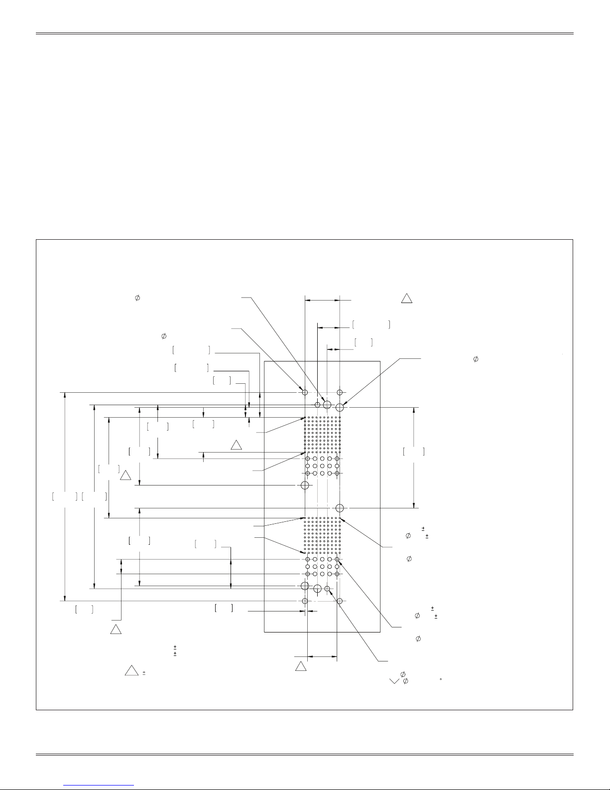
PCB LAYOUT AND MOUNTING
QUADRAPADDLE SIGNAL/MICRO POWER OR MICRO COAXIAL MODULE, RECEIVER,
ICON, 100/15 POSITION, WITH TWIN FEMALE SIGNAL • PART # 510 160 112
QUADRAPADDLE SIGNAL/MICRO POWER OR MICRO COAXIAL MODULE, RECEIVER,
ICON, 100/15 POSITION, FULLY LOADED WITH MALE POSTS • PART # 510 160 113
PCB layout for the iCon Receiver, Part # 310 123 101 loaded with two 510 160 112/113 modules. 200 thru
hole and pad diameters are for VPC QuadraPaddle Adapter Contact, Part #610 138 117; 30 thru hole
and pad diameters are for VPC Micro Power contact, Part # 610 142 102. The size of these holes may
be different if a header from a different manufacturer is used.
Also shown are optional clearance holes.
VPC modules/pin mount this side.
66.04
2.600
CLEARANCE HOLES
2 X
.200[5.08] THRU
CLEARANCE HOLES
FOR FRAME MOUNTING SCREWS
51.05
2.01
1
51.05
2.01
4 X
35.31
1.39
.135[3.43] THRU
16.38±0.25
.645±.010
6.48±0.25
.255±.010
22.86
9 PLCS. @ .100
TYP. 2 PATTERNS
FOR ACCESS TO KEYING FEATURE MOUNTING SCREWS
5.39
120.65
4.750
136.91
.90
19.30
.76
.900
9 PLCS. @ .100
TYP. 2 PATTERNS
14.61±0.25
.575±.010
8.26
8.26
.325
PIN A1
1
PIN A10
PIN A1
PIN A10
.325
TYP.
1
CLEARANCE HOLES
4 X
.200[5.08] THRU
66.04
2.60
0.08]
[0.94
.037 .003
PLATED THRU HOLE
[1.52]
.060 PAD
TYP .200 PLCS EACH
9.65
.38
2 PLCS. @ .190
TYP. 2 PATTERNS
RECOMMENDED PCB LAYOUT
1
CONNECTOR MOUNTS THIS SIDE
TOLERANCES ARE:
.XX=
[0.25] .01
.XXX=
UNLESS OTHERWISE SPECIFIED
1
.0021 LOCATION TOLERANCE
APPLIES TO PLATED THRU HOLES
TOLERANCE N0N-ACCUMULATIVE
[0.13] .005
8-6 For the most current information available, visit www.vpc.com.
1.78
.07
TYP.
4 PLCS. @ .190
TYP. 2 PATTERNS
.760
TYP.
[2.54
0.08]
.100 .003
PLATED THRU HOLES
[3.18]
.125 PAD
TYP 30 PLCS EACH
1
3&%02817,1*+2/(686(6
;7+5($')/$7+($'6&5(:6
7+58$//
;
;
)$56,'(237,21$/
6/7/18
Page 23
ICON USER’S MANUAL: SECTION 8 VIRGINIA PANEL CORPORATION
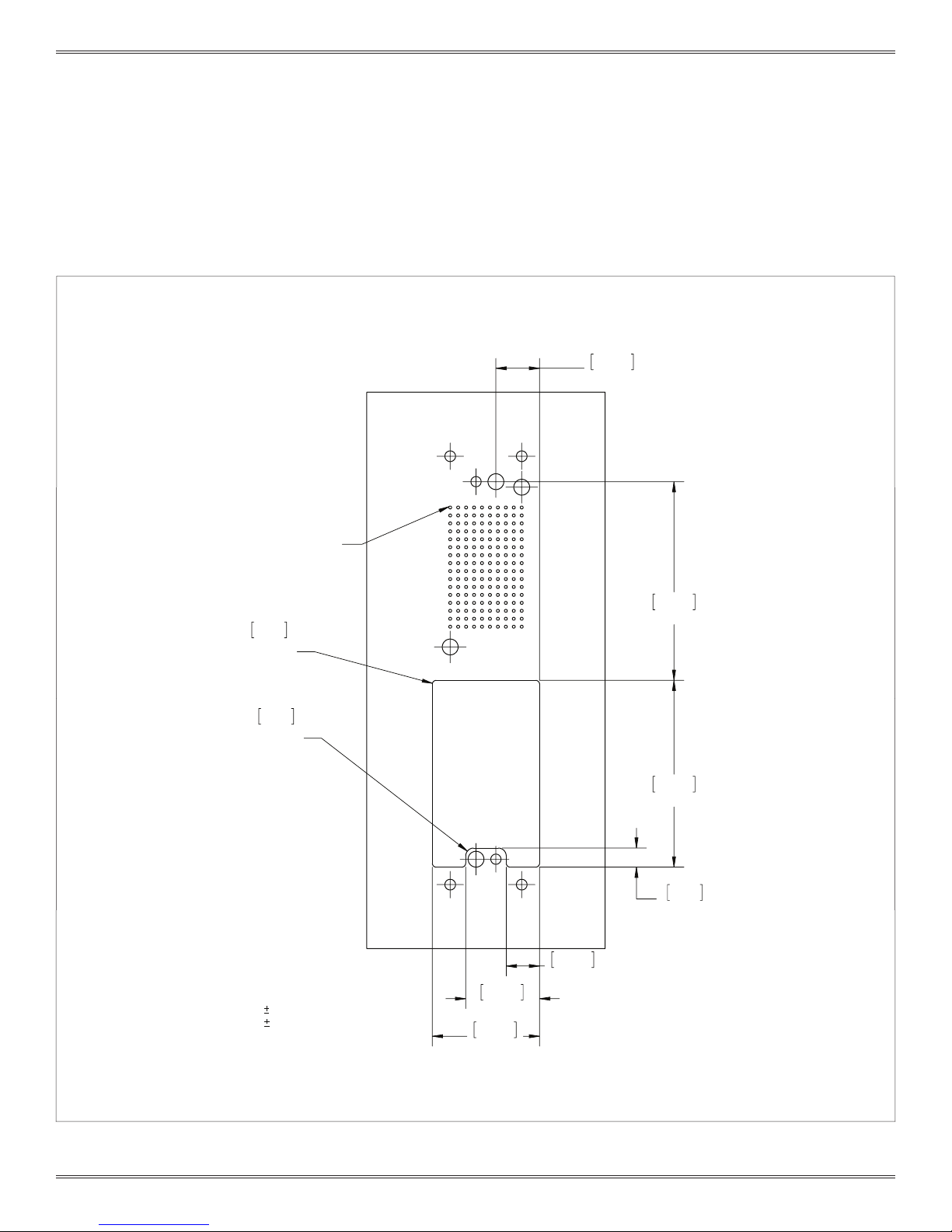
PCB LAYOUT AND MOUNTING
ONE PCB MOUNTED MODULE AND ONE DISCRETELY WIRED MODULE
PCB layout for the iCon Receiver, Part # 310 123 101 loaded with one PCB mounted module
and one discretely wired module. Also shown are optional clearance holes. VPC modules/
pin mount this side. See Section 8-4 thru 8-6 for option hole pattern dimensioning.
13.97
.55
PIN A1
1.27
R.05
2 PLCS.
2.54
R.10
2 PLCS.
RECOMMENDED PCB LAYOUT
CONNECTOR MOUNTS THIS SIDE
TOLERANCES ARE:
.XX=
.XXX=
UNLESS OTHERWISE SPECIFIED
[0.25] .01
[0.13] .005
34.29
23.62
.93
1.35
63.50
10.92
.43
2.50
59.69
2.35
6.10
.24
8-7 For the most current information available, visit www.vpc.com.
6/7/18
Page 24

ICON USER’S MANUAL: SECTION 9 VIRGINIA PANEL CORPORATION
TROUBLESHOOTING
ITA Frame is not lined up when in the process of engagement with Receiver
• This may indicate that the ITA was dropped and is out of alignment or that a module is not mating with its intended module.
• Remove and inspect the ITA for alignment
• Check for foreign objects/tools
• Inspect the matching of modules - Power ITA Module to mate with Power Receiver Module, etc.
• The keying pin locations do not mate.
• The handle is installed wrong (“ITA ICON COVER INSTALLATION”).
9-1 For the most current information available, visit www.vpc.com
Forceful engagement of the Receiver and the ITA
will result in serious damage to multiple par ts of
the system (Modules, Receiver, ITA and Contacts)!
6/7/18
 Loading...