

VPC G12, G12x User Manual

G12/G12x USER’S MANUAL
TABLE OF CONTENTS
SECTION 1 SLIDE CONFIGURATION
SECTION 2 SLIDE CONFIGURATION ACCESSORIES
SECTION 3 TABLETOP CONFIGURATION
SECTION 4 TABLETOP CONFIGURATION ACCESSORIES
SECTION 5 RACK MOUNT CONFIGURATION
SECTION 6 RACK MOUNT CONFIGURATION ACCESSORIES
SECTION 7 HANDLE REMOVAL AND REPOSITIONING
SECTION 8 ITA ENCLOSURES
SECTION 9 ACCESSORIES
SECTION 10 ITA AND RECEIVER ENGAGEMENT
SECTIO N 11 TROUBLESHOOTING AND PRECAUTIONARY NOTES
Please note that any printed or downloaded User Manuals or Procedure Sheets may not reect the most current
revisions. The information contained in these materials is subject to change.
For the most current information available, visit www.vpc.com.
10/17/18
G12/G12 x USER’S MANUAL: SECTION 1 VIRGINIA PANEL CORPORATION
TOP VIEW
SLIDE CONFIGURATION INSTALLATION
20” SLIDE KIT (FITS 20” – 22” DEEP RACKS [508 - 558.8]) • PART # 310 113 409
24” SLIDE KIT (FITS 24” – 26” DEEP RACKS [609.6 - 660.4]) • PART # 310 113 410
28” SLIDE KIT (FITS 28” - 30” DEEP RACKS [711.2 - 762]) • PART # 310 113 451
30” SLIDE KIT (FITS 30” – 32” DEEP RACKS [762 - 812.8]) • PART # 310 113 411
36” SLIDE KIT (FITS 34” – 38” DEEP RACKS [863.6 - 965.2]) • PART # 310 113 500
Slides can be used with both the 15" and 20" G12/G12x
receivers. The slide kits include a mounting bracket kit, slides
and hardware. Choose your slide kit based on the distance
from rail to rail and verify that the slides will not interfere with
the rack enclosure. Each kit will suppor t 180 lbs.
TOOLS REQUIRED
Phillips Head Screwdriver
Flat Head Screwdr iver
³/
Allen Wrench
32
DETERMINE YOUR SLIDE KIT
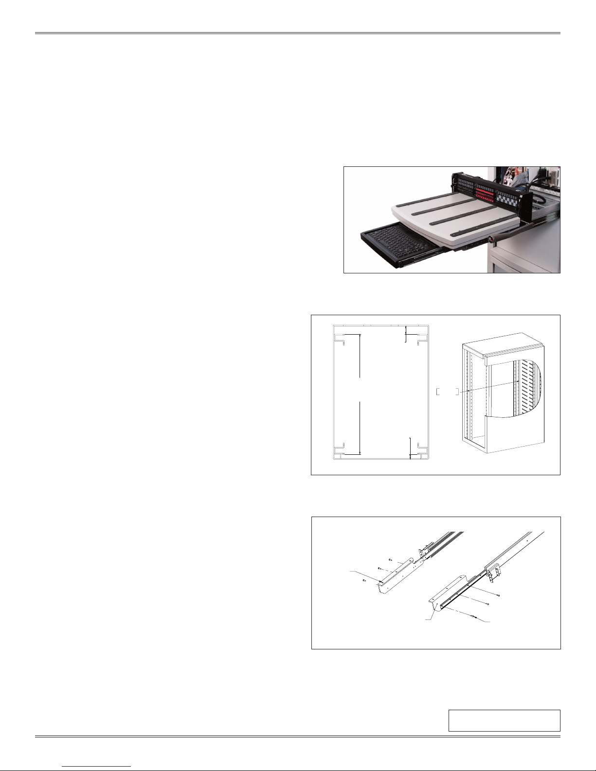
1. Measure dimension A as shown in Figure A to determine the
proper slide kit.
NOTE: Make sure the slide length does not exceed dimensions A
plus B.
DIMENSION B
[50.8]
2.00
INSTALLATION
1. Install slides using manufacturer’s instructions. A hard copy is
included with the slide kit.
( ww w.accuride.com/Resources/pdf/3507-r4-0309.pdf)
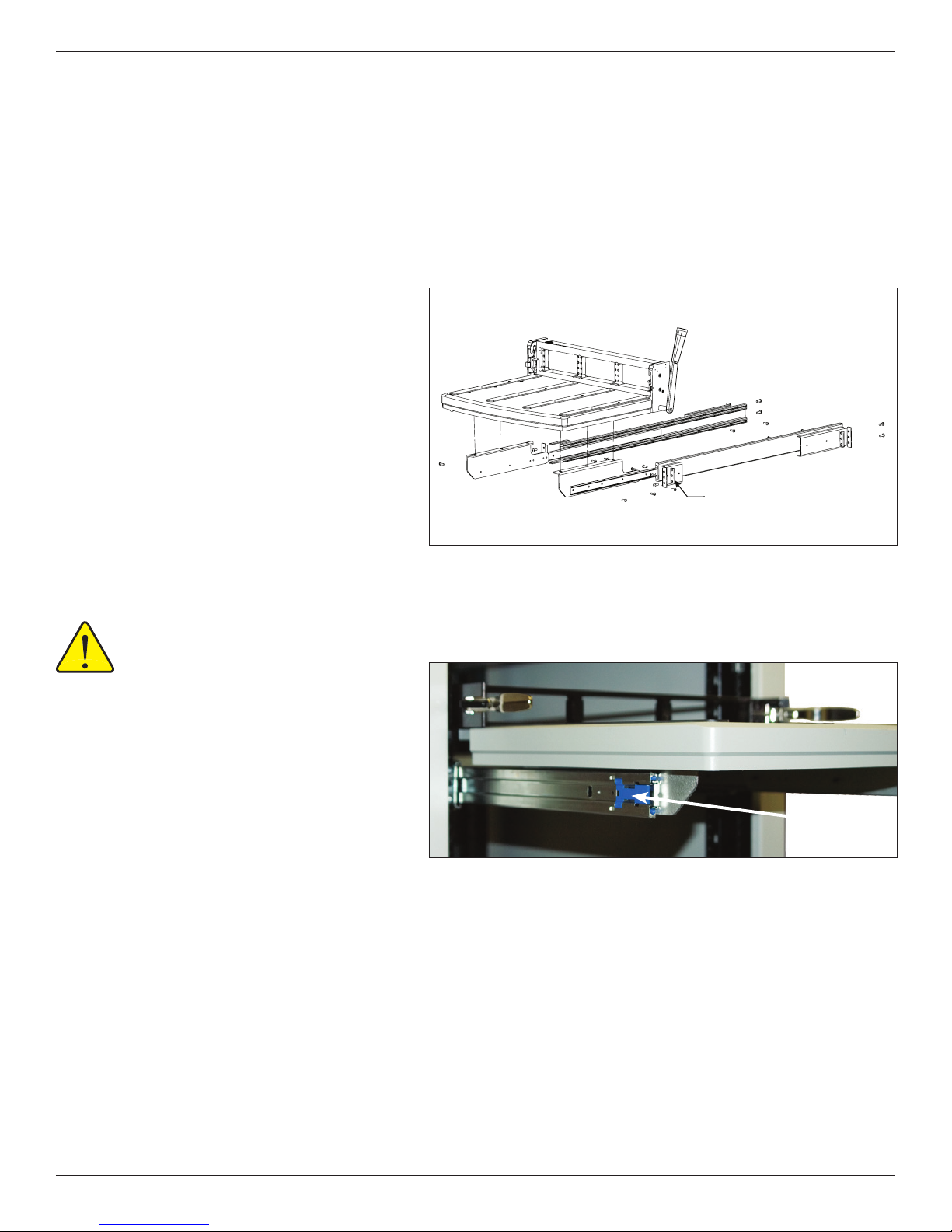
2. Attach platform mounting brackets to slides (Figure B).
NOTE: The screws will overhang the bracket holes by 3/8". These
screws will also be used to mount the keyboard tray kit, Part #
310 113 43 9.
Continued on next page...
DIMENSION A
[749.3]
29.50
DIMENSION C
FRONT OF RACK
[31.75]
1.25
749.30
29.50
Figure A. If dimension C exceeds 1" use the Rack Extender Kit,
Part # 310 113 406 for G12 or Part # 310 113 519 for G12x.
PLATFORM
MOUNTING
BRACKETS
G12 RECEIVER SUPPORTS
FOR MOUNTING PLATFORM
TO SLIDES
SLIDE TO BRACKET
MOUNTING HARDWARE
Figure B. The platform mounting brackets are threaded so
washers and nuts will not need to be locked.
1-1
For the most current information available, visit www.vpc.com
Dimensions shown: [millimeters]
inches
10/17/18
G12/G12 x USER’S MANUAL: SECTION 1 VIRGINIA PANEL CORPORATION
SLIDE CONFIGURATION INSTALLATION
20” SLIDE KIT (FITS 20” – 22” DEEP RACKS [508 - 558.8]) • PART # 310 113 409
24” SLIDE KIT (FITS 24” – 26” DEEP RACKS [609.6 - 660.4]) • PART # 310 113 410
28” SLIDE KIT (FITS 28” - 30” DEEP RACKS [711.2 - 762]) • PART # 310 113 451
30” SLIDE KIT (FITS 30” – 32” DEEP RACKS [762 - 812.8]) • PART # 310 113 411
36” SLIDE KIT (FITS 34” – 38” DEEP RACKS [863.6 - 965.2]) • PART # 310 113 500
3. Remove the rubber feet.
4. Attach the G12/G12x platform to the platform
mounting brackets after removing the rubber feet
(Figure C).
NOTE: If you are installing a cable tray or instrument
brackets, do not attach the platform until those
accessories are installed.
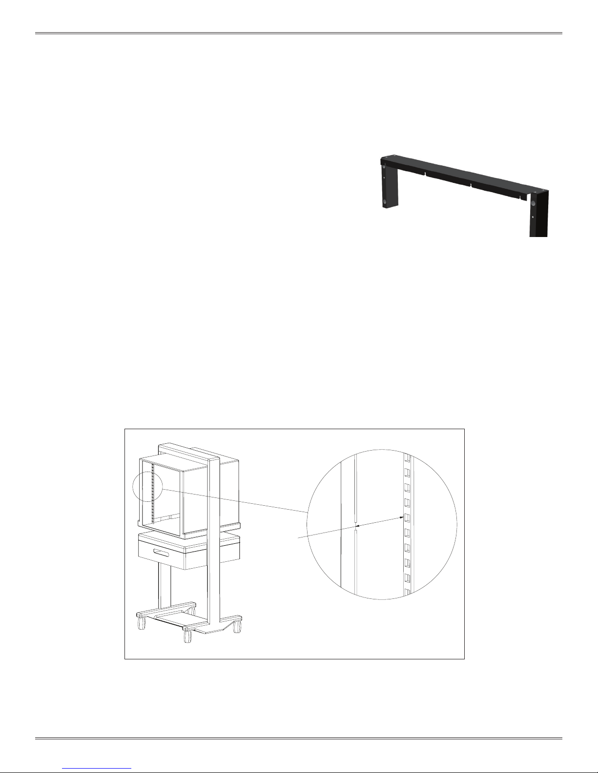
5. Pull the receiver out as far as possible. The slides
will lock in position. Push the blue tabs located on
the middle section of the slides (Figure D). Apply
pressure to push the receiver back in toward the
rack. The smaller inner slides move into the middle
section, which should not move. Push receiver until
it backs into the rack. The mounting screws can now
be used.
Figure C. Use the existing #8-32 at head screws, washers, and hex nuts to
secure the platform to the brackets.
BAR NUT
ALWAYS SUPPORT THE RECEIVER AND
PLATFORM WITH THE MOST ROBUST
(MIDDLE) SECTION OF THE SLIDES.
ensure proper support when extending the
receiver and table away from the rack, stop
the receiver and platform at approximately 6” from the
rack. Reach around to the rear of the receiver to the
slides underneath on both sides. Manually extend the
middle section of the slides forward until fully underneath
the platform. The receiver and platform may then be
extended while holding this middle slide in place. If
completed properly, the middle section of the slides will
remain underneath the platform and offer the strongest
support.
6. Secure receiver to rack.
To
BLUE TAB
Figure D. The slides will support 180 pounds. VPC recommends removing the
ITA/Fixture when extending the slides for wiring access and maintenance.
1-2
For the most current information available, visit www.vpc.com
10/17/18
G12/G12 x USER’S MANUAL: SECTION 2 VIRGINIA PANEL CORPORATION
SLIDE CONFIGURATION ACCESSORIES
RACK EXTENDER KIT, G12, 1.5" DEEP • PART # 310 113 406
RACK EXTENDER KIT, G12X, 1.5” DEEP • PART # 310 113 519
The G12/G12x is designed to easily t 19" standard racks when
used in the slide con guration. Although mounting rail dimensions
are standardized, there may be variances in the rack enclosure
design. VPC offers a rack extender kit for rails that are recessed
more than 1". The Rack Extender Kit has a maximum depth of 2.5".
TOOLS REQUIRED
5
/32 Allen Wrench
Phillips Head Screwdriver
INSTALLATION
1. To determine if a Rack E xtender Kit is needed, verify that the distance bet ween the front of the rack enclosure and the rail is between
1" and 2.5" (Figure A).
2. Attach the mounting rack mating sur face on the extender brackets to the recessed rail with the cap screws. Do not fully tighten until
until the cover plate is attached.
3. Attach the cover to the brackets with the fl at head screws.
4. With the extender kit in place, secure the G12 receiver to the mating surface on the extender brackets with #10-32 cap screws.
NOTE: The #10-32 cap screws are provided with the G12 receiver.
DIMENSION C
DIMENSION C
2.5“[63.5mm]
[101.6]
4.00
Figure A. Rack Extender Kits are used when the rails are recessed more than 1".
2-1
For the most current information available, visit www.vpc.com
10/17/18
G12/G12 x USER’S MANUAL: SECTION 2 VIRGINIA PANEL CORPORATION
INSTRUMENT BRACKET INSTALLATION
PART # 310 113 453
The instrument brackets mount to the inner sl ide and provide
maintenance access to the chassis and the instruments.
NOTE: This instrument bracket kit does not work with the 20”
or 24” slide kits.
TOOLS REQUIRED
5
/32 Allen Wrench
Phillips Head Screwdriver
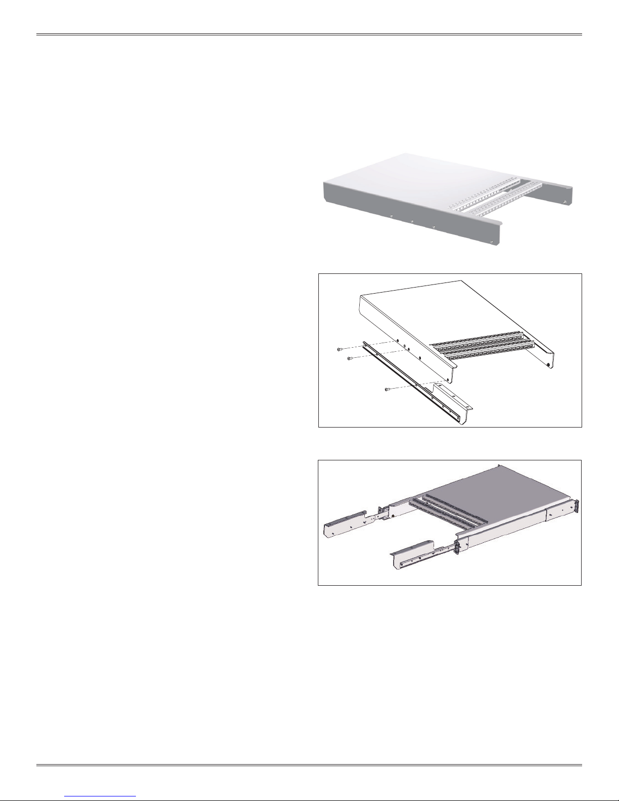
INSTALLATION
1. Depress the blue tab on the inner slide and remove.
2. Attach one of the brackets to the slide using three #8-32
button head screws. The left bracket assembly is shown in
Figure A.
3. Attach the remaining bracket to the other inner slide. If you
are also installing a cable tray, do so before reinstalling the
slides and attaching the plate. See Cable Tray Installation
instructions in this section.
Continued on next page...
Figure A. The brackets are identical par ts and only the front two
holes on each bracket are designed to line up with the slides.
Figure B. The slots on the instrument brackets are designed to
accept a strap should you want to secure your chassis.
2-2
For the most current information available, visit www.vpc.com
10/17/18
G12/G12 x USER’S MANUAL: SECTION 2 VIRGINIA PANEL CORPORATION
INSTRUMENT BRACKET INSTALLATION
PART # 310 113 453
5. Reinstall the inner slides.
• Slide the left mid-section of the slide all the way out, you will feel it
lock into position.
• Feed the matching inner slide into position and ensure the inner
section rides into place with the roller bearings seated into the
groove.
• Push the inner slide in about 6-8 inches and then pull out the right
side. Slide the track of the mid-section over the right side of the
inner slide.
• Pull the slide out until the position matches the left side.
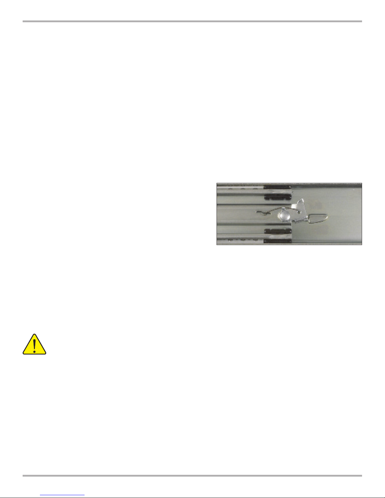
• Reach to the back of the middle slides and release the spr ing
locking mechanism (Figure C).
NOTE: At this time, both sides should be partially installed when it will
no longer proceed into the rack because the support tab on the
instrument brackets will hit the slide mounting bracket.
6. Rotate both instrument brackets inward so the support tabs
can pass the mounting brackets. Continue to push (install slides
simultaneously) into position. Remember to push the blue tabs
to allow the inner slide to continue to travel into the middle slide
section.
NOTE: The middle section will not go into the outer section until the
inner section has been fully installed into the middle section.
7. Tighten the slide mounting screws.
MAKE SURE ALL SCREW HEADS HAVE BEEN SECURELY
TIGHTENED. ONLY USE 8-32 BUTTON HEAD SCREWS.
Figure C. Spring-locking mechanism.
2-3
For the most current information available, visit www.vpc.com
10/17/18
 Loading...