


G12/G12x USER’S MANUAL
TABLE OF CONTENTS
SECTION 1 SLIDE CONFIGURATION
SECTION 2 SLIDE CONFIGURATION ACCESSORIES
SECTION 3 TABLETOP CONFIGURATION
SECTION 4 TABLETOP CONFIGURATION ACCESSORIES
SECTION 5 RACK MOUNT CONFIGURATION
SECTION 6 RACK MOUNT CONFIGURATION ACCESSORIES
SECTION 7 HANDLE REMOVAL AND REPOSITIONING
SECTION 8 ITA ENCLOSURES
SECTION 9 ACCESSORIES
SECTION 10 ITA AND RECEIVER ENGAGEMENT
SECTIO N 11 TROUBLESHOOTING AND PRECAUTIONARY NOTES
Please note that any printed or downloaded User Manuals or Procedure Sheets may not reect the most current
revisions. The information contained in these materials is subject to change.
For the most current information available, visit www.vpc.com.
10/17/18
G12/G12 x USER’S MANUAL: SECTION 1 VIRGINIA PANEL CORPORATION
TOP VIEW
SLIDE CONFIGURATION INSTALLATION
20” SLIDE KIT (FITS 20” – 22” DEEP RACKS [508 - 558.8]) • PART # 310 113 409
24” SLIDE KIT (FITS 24” – 26” DEEP RACKS [609.6 - 660.4]) • PART # 310 113 410
28” SLIDE KIT (FITS 28” - 30” DEEP RACKS [711.2 - 762]) • PART # 310 113 451
30” SLIDE KIT (FITS 30” – 32” DEEP RACKS [762 - 812.8]) • PART # 310 113 411
36” SLIDE KIT (FITS 34” – 38” DEEP RACKS [863.6 - 965.2]) • PART # 310 113 500
Slides can be used with both the 15" and 20" G12/G12x
receivers. The slide kits include a mounting bracket kit, slides
and hardware. Choose your slide kit based on the distance
from rail to rail and verify that the slides will not interfere with
the rack enclosure. Each kit will suppor t 180 lbs.
TOOLS REQUIRED
Phillips Head Screwdriver
Flat Head Screwdr iver
³/
Allen Wrench
32
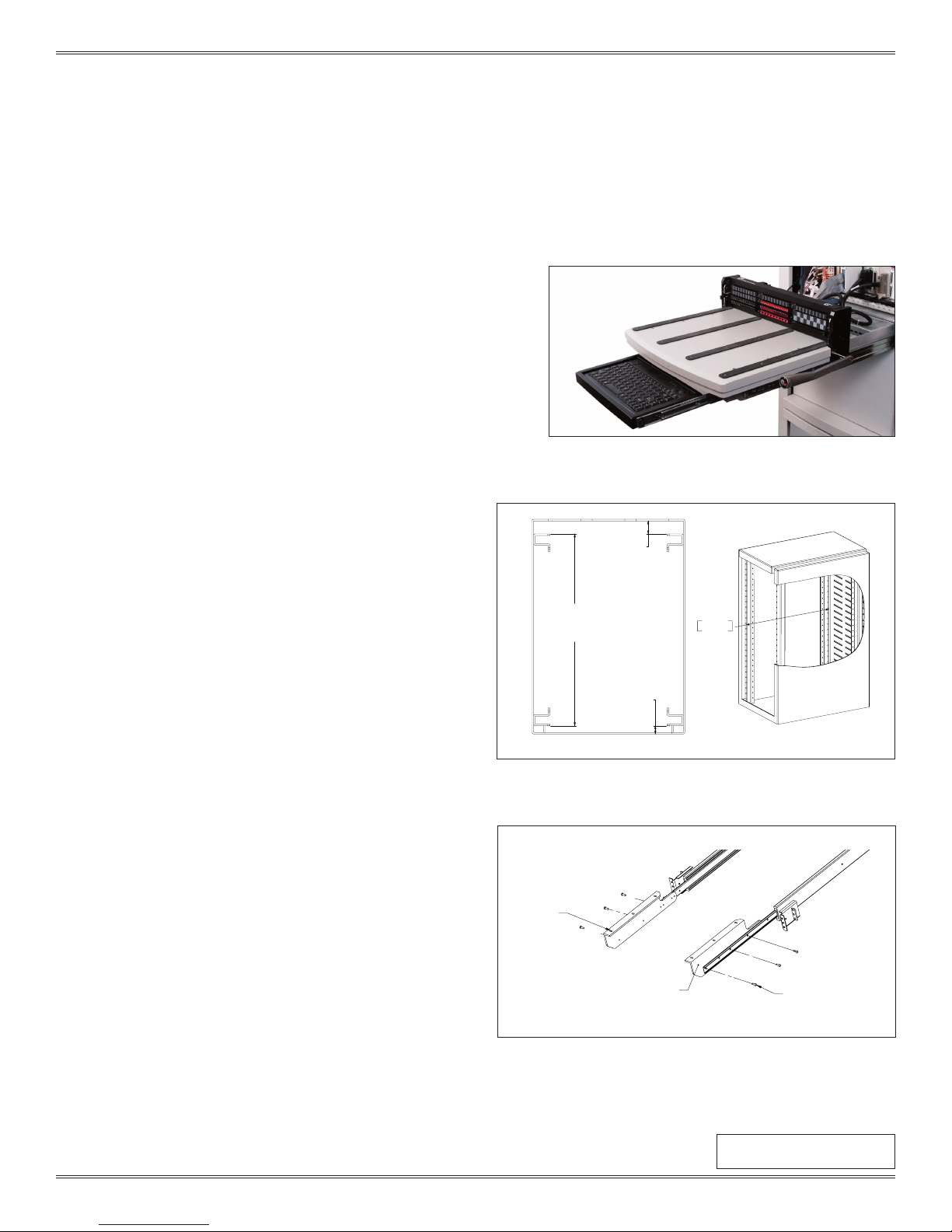
DETERMINE YOUR SLIDE KIT
1. Measure dimension A as shown in Figure A to determine the
proper slide kit.
NOTE: Make sure the slide length does not exceed dimensions A
plus B.
DIMENSION B
[50.8]
2.00
INSTALLATION
1. Install slides using manufacturer’s instructions. A hard copy is
included with the slide kit.
( ww w.accuride.com/Resources/pdf/3507-r4-0309.pdf)
2. Attach platform mounting brackets to slides (Figure B).
NOTE: The screws will overhang the bracket holes by 3/8". These
screws will also be used to mount the keyboard tray kit, Part #
310 113 43 9.
Continued on next page...
DIMENSION A
[749.3]
29.50
DIMENSION C
FRONT OF RACK
[31.75]
1.25
749.30
29.50
Figure A. If dimension C exceeds 1" use the Rack Extender Kit,
Part # 310 113 406 for G12 or Part # 310 113 519 for G12x.
PLATFORM
MOUNTING
BRACKETS
G12 RECEIVER SUPPORTS
FOR MOUNTING PLATFORM
TO SLIDES
SLIDE TO BRACKET
MOUNTING HARDWARE
Figure B. The platform mounting brackets are threaded so
washers and nuts will not need to be locked.
1-1
For the most current information available, visit www.vpc.com
Dimensions shown: [millimeters]
inches
10/17/18
G12/G12 x USER’S MANUAL: SECTION 1 VIRGINIA PANEL CORPORATION
SLIDE CONFIGURATION INSTALLATION
20” SLIDE KIT (FITS 20” – 22” DEEP RACKS [508 - 558.8]) • PART # 310 113 409
24” SLIDE KIT (FITS 24” – 26” DEEP RACKS [609.6 - 660.4]) • PART # 310 113 410
28” SLIDE KIT (FITS 28” - 30” DEEP RACKS [711.2 - 762]) • PART # 310 113 451
30” SLIDE KIT (FITS 30” – 32” DEEP RACKS [762 - 812.8]) • PART # 310 113 411
36” SLIDE KIT (FITS 34” – 38” DEEP RACKS [863.6 - 965.2]) • PART # 310 113 500
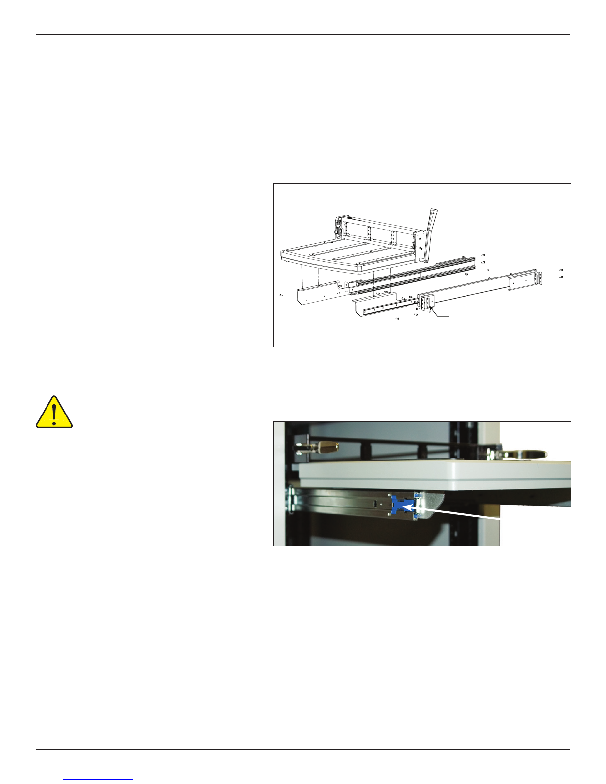
3. Remove the rubber feet.
4. Attach the G12/G12x platform to the platform
mounting brackets after removing the rubber feet
(Figure C).
NOTE: If you are installing a cable tray or instrument
brackets, do not attach the platform until those
accessories are installed.
5. Pull the receiver out as far as possible. The slides
will lock in position. Push the blue tabs located on
the middle section of the slides (Figure D). Apply
pressure to push the receiver back in toward the
rack. The smaller inner slides move into the middle
section, which should not move. Push receiver until
it backs into the rack. The mounting screws can now
be used.
Figure C. Use the existing #8-32 at head screws, washers, and hex nuts to
secure the platform to the brackets.
BAR NUT
ALWAYS SUPPORT THE RECEIVER AND
PLATFORM WITH THE MOST ROBUST
(MIDDLE) SECTION OF THE SLIDES.
ensure proper support when extending the
receiver and table away from the rack, stop
the receiver and platform at approximately 6” from the
rack. Reach around to the rear of the receiver to the
slides underneath on both sides. Manually extend the
middle section of the slides forward until fully underneath
the platform. The receiver and platform may then be
extended while holding this middle slide in place. If
completed properly, the middle section of the slides will
remain underneath the platform and offer the strongest
support.
6. Secure receiver to rack.
To
BLUE TAB
Figure D. The slides will support 180 pounds. VPC recommends removing the
ITA/Fixture when extending the slides for wiring access and maintenance.
1-2
For the most current information available, visit www.vpc.com
10/17/18
G12/G12 x USER’S MANUAL: SECTION 2 VIRGINIA PANEL CORPORATION
SLIDE CONFIGURATION ACCESSORIES
RACK EXTENDER KIT, G12, 1.5" DEEP • PART # 310 113 406
RACK EXTENDER KIT, G12X, 1.5” DEEP • PART # 310 113 519
The G12/G12x is designed to easily t 19" standard racks when
used in the slide con guration. Although mounting rail dimensions
are standardized, there may be variances in the rack enclosure
design. VPC offers a rack extender kit for rails that are recessed
more than 1". The Rack Extender Kit has a maximum depth of 2.5".
TOOLS REQUIRED
5
/32 Allen Wrench
Phillips Head Screwdriver
INSTALLATION
1. To determine if a Rack E xtender Kit is needed, verify that the distance bet ween the front of the rack enclosure and the rail is between
1" and 2.5" (Figure A).
2. Attach the mounting rack mating sur face on the extender brackets to the recessed rail with the cap screws. Do not fully tighten until
until the cover plate is attached.
3. Attach the cover to the brackets with the fl at head screws.
4. With the extender kit in place, secure the G12 receiver to the mating surface on the extender brackets with #10-32 cap screws.
NOTE: The #10-32 cap screws are provided with the G12 receiver.
DIMENSION C
DIMENSION C
2.5“[63.5mm]
[101.6]
4.00
Figure A. Rack Extender Kits are used when the rails are recessed more than 1".
2-1
For the most current information available, visit www.vpc.com
10/17/18
G12/G12 x USER’S MANUAL: SECTION 2 VIRGINIA PANEL CORPORATION
INSTRUMENT BRACKET INSTALLATION
PART # 310 113 453
The instrument brackets mount to the inner sl ide and provide
maintenance access to the chassis and the instruments.
NOTE: This instrument bracket kit does not work with the 20”
or 24” slide kits.
TOOLS REQUIRED
5
/32 Allen Wrench
Phillips Head Screwdriver
INSTALLATION
1. Depress the blue tab on the inner slide and remove.
2. Attach one of the brackets to the slide using three #8-32
button head screws. The left bracket assembly is shown in
Figure A.
3. Attach the remaining bracket to the other inner slide. If you
are also installing a cable tray, do so before reinstalling the
slides and attaching the plate. See Cable Tray Installation
instructions in this section.
Continued on next page...
Figure A. The brackets are identical par ts and only the front two
holes on each bracket are designed to line up with the slides.
Figure B. The slots on the instrument brackets are designed to
accept a strap should you want to secure your chassis.
2-2
For the most current information available, visit www.vpc.com
10/17/18
G12/G12 x USER’S MANUAL: SECTION 2 VIRGINIA PANEL CORPORATION
INSTRUMENT BRACKET INSTALLATION
PART # 310 113 453
5. Reinstall the inner slides.
• Slide the left mid-section of the slide all the way out, you will feel it
lock into position.
• Feed the matching inner slide into position and ensure the inner
section rides into place with the roller bearings seated into the
groove.
• Push the inner slide in about 6-8 inches and then pull out the right
side. Slide the track of the mid-section over the right side of the
inner slide.
• Pull the slide out until the position matches the left side.
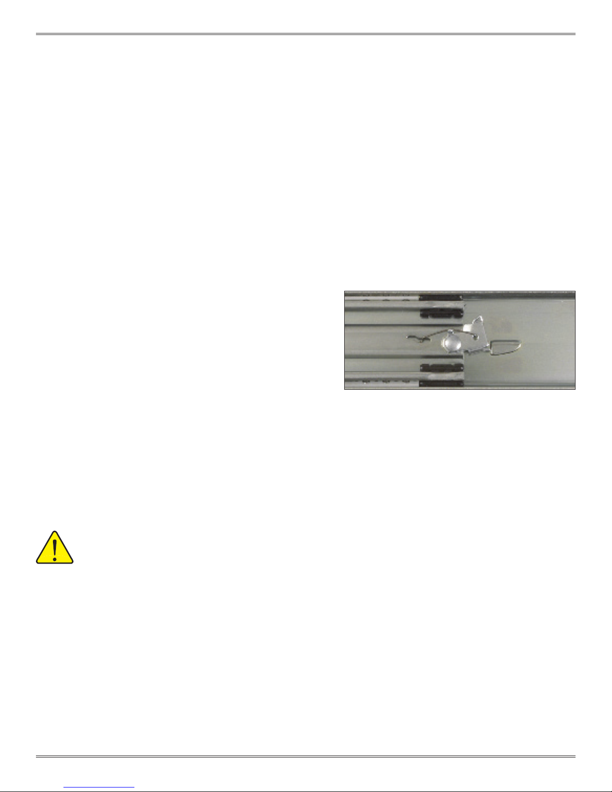
• Reach to the back of the middle slides and release the spr ing
locking mechanism (Figure C).
NOTE: At this time, both sides should be partially installed when it will
no longer proceed into the rack because the support tab on the
instrument brackets will hit the slide mounting bracket.
6. Rotate both instrument brackets inward so the support tabs
can pass the mounting brackets. Continue to push (install slides
simultaneously) into position. Remember to push the blue tabs
to allow the inner slide to continue to travel into the middle slide
section.
NOTE: The middle section will not go into the outer section until the
inner section has been fully installed into the middle section.
7. Tighten the slide mounting screws.
MAKE SURE ALL SCREW HEADS HAVE BEEN SECURELY
TIGHTENED. ONLY USE 8-32 BUTTON HEAD SCREWS.
Figure C. Spring-locking mechanism.
2-3
For the most current information available, visit www.vpc.com
10/17/18

G12/G12 x USER’S MANUAL: SECTION 2 VIRGINIA PANEL CORPORATION
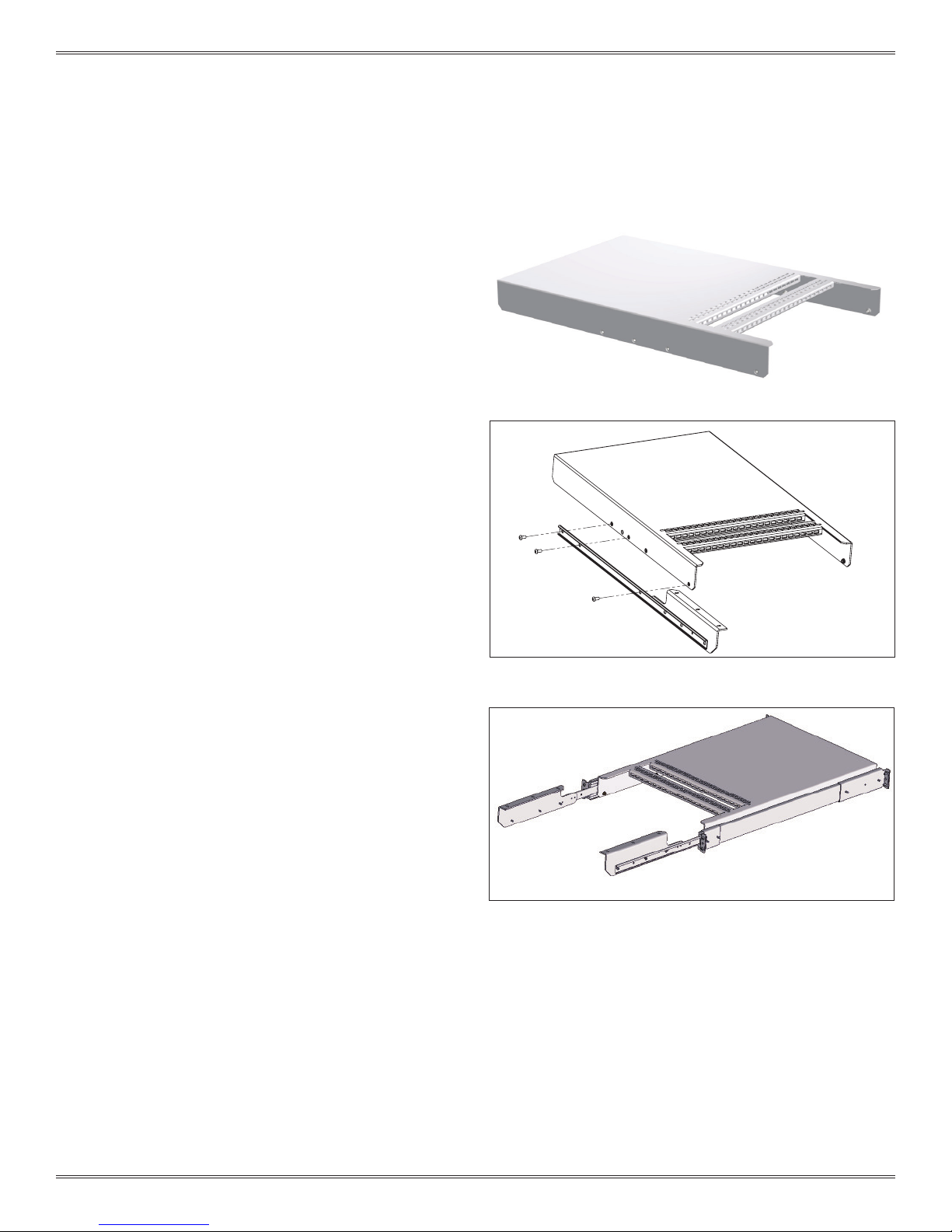
SLIDE CONFIGURATION ACCESSORIES
CABLE TRAY • PART # 310 113 424
The cable tray is used for strain relief and cable management.
The horizontal and vertical anges provide tie down options that
allow you to bend and route your cables as needed and also
present a secure and reliable way to protect your investment.
NOTE: The cable tray does not work with the 20” or 24” slide kits
or the instrument bracket kit with strain relief.
TOOLS REQUIRED
3
32
/
Allen wrench
CABLE TRAY INSTALLATION
1. Loosen the slide mounting screws by one turn.
2. Depress the blue tab and remove the inner slides.
3. Attach the cable tray to the slides with #8-32 screws as shown in Figure A.
Figure A. The angled side of the cable tray should face the G12/G12x receiver, and with shorter
slide kits the cable tray will sit below the lip of the instrument brackets.
4. Install the inner slides and cable tray assembly into the rack. See Instrument Bracket Installation instructions in this section for more
detail.
5. Tighten the slide mounting screws.
2-4
For the most current information available, visit www.vpc.com
10/17/18

G12/G12 x USER’S MANUAL: SECTION 2 VIRGINIA PANEL CORPORATION
KEYBOARD WITH TOUCHPAD
[721.36]
KEYBOARD TRAY KIT INSTALLATION
PART # 310 113 439
The Keyboard Tray Kit mounts below the platfor m on the
G12 or G12x receiver. The kit includes a keyboard with
touchpad and 58" long USB connector, keyboard tray,
and 12" slides.
TOOLS REQUIRED
3
32
/
Allen wrench
28.4
12 INCH SLIDE
MOVEMENT
13.0
[330.2]
13.3
[337.82]
MOUNTING BRACKET, RIGHTMOUNTING BRACKET, LEFT
USB KEYBOARD
CONNECTOR.
12 INCH SLIDES
RUBBER GROMMET
KEYBOARD TRAY
1.2
[30.48]
Figure A. Keyboard Tray Kit, Part # 310 113 439, includes components listed above and
mounting hardware.
Continued on next page...
2-5
For the most current information available, visit www.vpc.com
Dimensions shown: [millimeters]
inches
10/17/18

G12/G12 x USER’S MANUAL: SECTION 2 VIRGINIA PANEL CORPORATION
KEYBOARD TRAY KIT INSTALLATION
PART # 310 113 439
INSTRUCTIONS
1. Attach the keyboard mounting brackets to the existing
platform mounting brackets. Use the #8-32 nuts
and lock washers to secure the keyboard mounting
brackets to the three screws extending from the
platform mounting brackets (Figure B).
2. Use the #8 -32 button head screws to attach the 12"
slides to the inner side of the keyboard brackets. The
manufacturer stamped identication on the slides
should be placed toward the rack. You need to adjust
the position of the slides to access the hole locations.
Hole locations are shown in Figure C.
3. Insert the keyboard into the keyboard tray. Wrap the
plastic strain relief around the cable near the back of
the keyboard and press into the hole provided on the
keyboard tray.
PLATFORM MOUNTING BRACKET
EXISTING #8-32 SCREWS
Figure B. Orient the keyboard mounting brackets to align with the three
screws that extend beyond the platform mounting bracket.
MOUNTING BRACKET, LEFT
4. Fully extend the 12” slides and mount the keyboard
tray, (Figure D). The different hole patterns allow for
variations in the overall extension of the keyboard tray.
Figure C. There are oating, self-locking fasteners in the keyboard
mounting brackets which prevent the screws from backing out. You will
notice the snug t when tightening the screws.
Figure D. The remaining 4 #8-32 button head screws are used to attach
the keyboard tray to the slides.
2-6
For the most current information available, visit www.vpc.com
10/17/18

G12/G12 x USER’S MANUAL: SECTION 3 VIRGINIA PANEL CORPORATION
TABLETOP CONFIGURATION
RECEIVER, G12, 12 MODULE • PART # 310 104 408 / 310 104 409
RECEIVER, G12X, 18 MODULE • PART # 310 104 410 / 310 104 411 / 310 104 422
G12/G12x receivers are shipped with four rubber feet
for portable tabletop applications. The four feet are
removable to expose ¼ -20 tapped holes and allow for
permanent mounting applications.
PERMANENT TABLETOP MOUNTING
1. Remove rubber feet from ¼-20 tapped holes beneath the platform.
2. Prepare the mounting surface using the dimensions provided in Figure A or B, and drill 0.257" [6.53 mm] minimum thru holes.
3. Secure the receiver to the mounting surface with ¼-20 screws and washers.
449.58
17.70
292.10
11.50
16.51
.65
Figure A. Receiver with 15" Platform, Part # 310 104 408 &
310 104 410.
85.60
3.37
449.58
17.70
419.10
16.50
16.51
Figure B. Receiver with 20" Platform, Par t # 310 104 409 &
310 104 411.
.65
85.60
3.37
3-1
For the most current information available, visit www.vpc.com
Dimensions shown: [millimeters]
inches
10/17/18

G12/G12 x USER’S MANUAL: SECTION 4 VIRGINIA PANEL CORPORATION
1.35
15.00
P
TABLETOP CONFIGURATION ACCESSORIES
REAR COVER, G12, TABLETOP CONFIGURATION • PART # 310 113 421
REAR COVER, G12X, TABLETOP CONFIGURATION • PART # 310 113 520
The rear cover is used to protect the wiring from the
tabletop mounted receiver to the instruments. The rear
cover includes neces sar y hardware to attach the G12/
G12x receiver to the tabletop.
TOOLS REQUIRED
³/32 Allen Wrench
REAR COVER INSTALLATION
1. Use the ³/32 Allen wrench with the provided #8 -32 screws and washers to attach the rear cover to the G12/G12x receiver. An
exploded view of the assembly is provided in Figure A.
Figure A. Rear cover, Part # 310 113 421, is designed to attach to the G12 receiver, Part # 310 104
408/409. Part # 310 113 520 is designed to attach to the G12x receiver, Part # 310 104 410/411.
OPTIONAL INSTALLATION
1. Rear covers can be permanently mounted to the tabletop using the dimensions provided in Figure B. Hardware is not included.
287.19
11.307
34.29
Figure B. The rubber feet included with the rear cover are not
necessary when permanently mounting the G12/G12x receiver.
381
6.60
.26 TY
Dimensions shown: [millimeters]
inches
4-1
For the most current information available, visit www.vpc.com
10/17/18

G12/G12 x USER’S MANUAL: SECTION 5 VIRGINIA PANEL CORPORATION
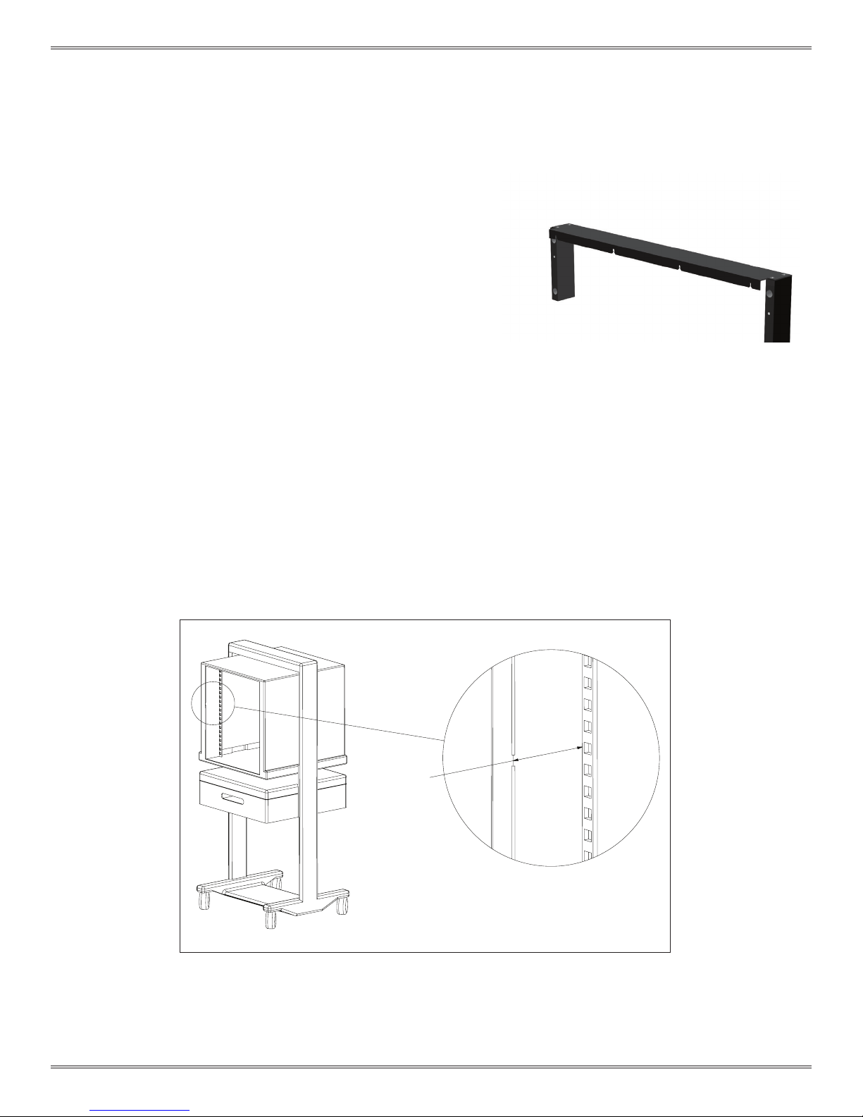
RACK MOUNT CONFIGURATION
RECEIVER, G12, 12 MODULE • PART # 310 104 338
The 15” G12 Receiver provides a platform for use with large
xtures. When this Receiver is xed mounted, it can support
up to 275 lbs.
TOOLS REQUIRED
5
/32 Allen Wrench
INSTALLATION
1. Place receiver over clip/cage nuts on rack, making sure they are aligned (Figure A).
Figure A.
2. Tighten screws in a cr iss-cross pattern to ensure even torque is applied.
5-1
For the most current information available, visit www.vpc.com
10/17/18

G12/G12 x USER’S MANUAL: SECTION 6 VIRGINIA PANEL CORPORATION
RACK MOUNT CONFIGURATION ACCESSORIES
RACK EXTENDER KIT, G12 • PART # 310 113 413
The Rack Mount Extender Block Kit is used for
mounting to racks with recessed mounting
rails. It is made of aluminum with a black
anodized nish. The Rack Extender Kit will allow
for a maximum rack depth of 3.5”.
TOOLS REQUIRED
5
/32 Allen Wrench
Phillips Head Screwdriver
Flat Head Screwdr iver
INSTALLATION
1. Verify that the distance from the front of
the rack enclosure to the rail is between 1"
and 3.5" (Figure A).
2. Attach the mounting rack mating surface
on the extender brackets (Figure B), to the
recessed rail with the cap screws. Do not
fully tighten until until the cover plate is
attached.
3. Attach the cover to the brackets with the
fl at head screws.
4. With the extender kit in place, secure the
G12 receiver to the G12 receiver mating
surface on the extender brackets with
#10-32 cap screws.
NOTE: The #10-32 cap screws are
provided with the G12 receiver.
*For a larger and easier-to-read drawing please
consul t the of fi cial drawing online at vpc.com.
Enter part # 310113413 and select the drawing link on
the right side of the Product Page.
Figure B.
DIMENSION C
DIMENSION C
3.5“[88.9mm]
[101.6]
4.00
Figure A. Rack Extender Kits are used when the rails are recessed more than 1".
4-4 0 Flat Hea d Screws
for mountin g Extender
10-32 x . 75 Button He ad
Socket Sc rews to secure
rack. 4 places .
M6 x 20 scr ews may
also be used (not
included).
Kit Top to r eceiver
6-1
For the most current information available, visit www.vpc.com
Left Extension
Figure B.
RIght Extension
10/17/18

G12/G12 x USER’S MANUAL: SECTION 7 VIRGINIA PANEL CORPORATION
310104325, 310104286, 310104408 & 310104409, : G12/G12x receiver
HANDLE REMOVAL AND REPOSITIONING
RECEIVER, G12 • PART # 310 104 325 / 310 104 334 / 310 104 408 / 310 104 409
RECEIVER, G12, LEFT HANDLE • PART # 310 104 356 & 310 104 359
RECEIVER, G12X • PART # 310 104 385 / 310 104 386 / 310 104 410 / 310 104 411
The G12/G12x receiver handle requires approximately 90° of
counter-clockwise travel for engagement and 90° of clockwise
travel for disengagement of the ITA. This handle is removable and
adjustable to accommodate different mounting conguration
requirements and for transport purposes.
TOOLS REQUIRED
3
32
/
Allen Wrench
REMOVAL INSTRUCTIONS
1. Remove the handle set screw with a 3/32 Allen wrench.
2. Remove the handle and reposition in 90˚ increments.
3. Replace the screw and tighten until the handle is secured tightly.
with a 15” platform show with handle in the
standard disengaged position.
310104334, 310104385, 310104410 & 310104411, : G12/G12x receiver
with a 20” platform show with handle in the
standard engaged position.
HANDLE CAN BE LOOSENED AND
ROTATED IN 90 DEGREE INCREMENTS.
362.79
14.28
430.10
16.93
560.32
22.06
493.01
19.41
7-1
For the most current information available, visit www.vpc.com
HANDLE CAN BE LOOSENED AND
ROTATED IN 90 DEGREE INCREMENTS.
Dimensions shown: [millimeters]
inches
10/17/18

G12/G12 x USER’S MANUAL: SECTION 8 VIRGINIA PANEL CORPORATION
44.45
G12 ITA ENCLOSURE
ENCLOSURE, G12 , FRONT MOUNT • PART # 410 112 665
ENCLOSURE, G12, FOR DISCRETE WIRING, 4" X 18" X 12 " • PART # 410 112 739
The front mounting G12 enclosure is available to meet your
testing needs. Custom enclosures are also available if the
standard is not applicable to your test system.
TOOLS REQUIRED
3 mm Allen Wrench
Phillips Head Screwdriver
ENCLOSURE MUST BE FLUSH TO BOTTOM OF ITA
FRAME. THE WIDTH MAY GROW TO CUSTOMERS
NEEDS WITH A SIMPLE ADJUSTMENT OF THE HANDLE
ON THE RECEIVER. THERE IS NO LIMIT TO THE HEIGHT
OF THE ENCLOSURE.
Figure A. Enclosures must be ush with the ITA bottom to ensure the proper function of the G12 system.
8-1
1.75
For more information visit vpc.com
84.84
3.34
Dimensions shown: [millimeters]
inches
10/17/18

G12/G12 x USER’S MANUAL: SECTION 8 VIRGINIA PANEL CORPORATION
31.75
ENCLOSURE MUST BE FLUSH TO BOTTOM OF IT
FRAME. THE WIDTH MAY GROW TO CUSTOMER
NEEDS WITH A SIMPLE ADJUSTMENT OF THE HANDLE
ON THE RECEIVER. THERE IS NO LIMIT TO THE HEIGH
OF THE ENCLOSURE.
G12X ITA ENCLOSURE
ENCLOSURE, G12X , FRONT MOUNT • PART # 410 112 849
ENCLOSURE, G12X, FOR DISCRETE WIRING, 4" X 18" X 12 " • PART # 410 112 856
The front mounting G12x enclosure is available to meet your
testing needs. Custom enclosures are also available if the
standard is not applicable to your test system.
TOOLS REQUIRED
3 mm Allen Wrench
Phillips Head Screwdriver
Figure A. Enclosures must be ush with the ITA bottom to ensure the proper function of the G12x system.
8-2
1.25
A
S
T
136.40
5.37
For more information visit vpc.com
Dimensions shown: [millimeters]
inches
10/17/18

G12/G12 x USER’S MANUAL: SECTION 9 VIRGINIA PANEL CORPORATION
KEYING PIN KIT, RECEIVER AND ITA ASSEMBLY
PART # 310 118 112
TOOLS REQUIRED
Allen Wrench
³/
32
INSTALLATION
1. Determine which locations in the receiver and ITA
will have keying pins installed and which will be open
according to Tabl e 1.
2. Install the required keying pin combination with the
3/32 Hex Wrench (Figure A).
NOTE: One keying pin kit will allow 6 variations. By using a
second keying pin kit, you can have up to 36 variations.
Table 1.
KEYING PIN LOCATIONS
PATTERN 1 PATTERN 4
RECEIVER ITA RECEIVER ITA
PIN A
INSTALLED
PIN B
OPEN
PIN A
INSTALLED
PIN B
INSTALLED
PIN A
OPEN
PIN B
OPEN
PIN C
INSTALLED
PIN D
OPEN
RECEIVER ITA RECEIVER ITA
PIN C
OPEN
PIN D
OPEN
RECEIVER ITA RECEIVER ITA
PIN C
INSTALLED
PIN D
INSTALLED
SCREW A
SCREW B
INSTALLED
PATTERN 2 PATTERN 5
SCREW A
SCREW B
PATTERN 3 PATTERN 6
SCREW A
INSTALLED
SCREW B
INSTALLED
OPEN
OPEN
OPEN
SCREW C
OPEN
SCREW D
INSTALLED
SCREW C
INSTALLED
SCREW D
INSTALLED
SCREW C
OPEN
SCREW D
OPEN
PIN A
OPEN
PIN B
INSTALLED
PIN A
OPEN
PIN B
INSTALLED
PIN A
INSTALLED
PIN B
OPEN
PIN C
OPEN
PIN D
INSTALLED
PIN C
INSTALLED
PIN D
OPEN
PIN C
OPEN
PIN D
INSTALLED
SCREW A
INSTALLED
SCREW B
OPEN
SCREW A
INSTALLED
SCREW B
OPEN
SCREW A
OPEN
SCREW B
INSTALLED
SCREW C
INSTALLED
SCREW D
OPEN
SCREW C
OPEN
SCREW D
INSTALLED
SCREW C
INSTALLED
SCREW D
OPEN
A
DETAIL A
SCALE 1 : 1.5
Figure A.
9-1
For the most current information available, visit www.vpc.com
Figure B.
DETAIL B
SCALE 1 : 1.5
B
10/17/18

G12/G12 x USER’S MANUAL: SECTION 10 VIRGINIA PANEL CORPORATION
G12 ITA & RECEIVER ENGAGEMENT
Prior to engaging an ITA with the receiver for the rst time, ensure all modules (ITA and receiver) are properly installed. This involves
inspection of modules to ensure proper mounting and to verif y module positioning. Module positions are shown in Figures A and B.
Modules must be installed such that Pin 1 of each respective mating receiver and ITA module pair are adjacent. VPC recommends that
Pin 1 always be positioned to the left in the receiver and ITA frames. All ITA Modules must match the respective receiver Modules. It is
crucial for all modules to be installed properly. G12x Only: The lower four module rows share the same description as on G12 (i.e. A1-A4).
The extended tier of the G12x is considered to be rows 5 or 6.
MODULE POSITION C5
MODULE POSITION C6
MODULE POSITION C1
MODULE POSITION C2
MODULE POSITION C3
MODULE POSITION C4
MODULE POSITION C5
MODULE POSITION C6
MODULE POSITION C1
MODULE POSITION C2
MODULE POSITION C3
MODULE POSITION C4
MODULE POSITION A1
MODULE POSITION A2
MODULE POSITION A3
MODULE POSITION A4
MODULE POSITION A1
MODULE POSITION A2
MODULE POSITION A3
MODULE POSITION A4
MODULE POSITION B1
MODULE POSITION B2
MODULE POSITION B3
MODULE POSITION B4
MODULE POSITION B1
MODULE POSITION B2
MODULE POSITION B3
MODULE POSITION B4
MODULE POSITION C1
MODULE POSITION C2
MODULE POSITION C3
MODULE POSITION C4
MODULE POSITION C1
MODULE POSITION C2
MODULE POSITION C3
MODULE POSITION C4
MODULE POSITION A5
MODULE POSITION A6
MODULE POSITION A1
MODULE POSITION A2
MODULE POSITION A3
MODULE POSITION A4
MODULE POSITION A5
MODULE POSITION A6
MODULE POSITION A1 MODULE POSITION B1
MODULE POSITION A2
MODULE POSITION A3
MODULE POSITION A4
MODULE POSITION B5
MODULE POSITION B6
MODULE POSITION B1
MODULE POSITION B2
MODULE POSITION B3
MODULE POSITION B4
MODULE POSITION B5
MODULE POSITION B6
MODULE POSITION B2
MODULE POSITION B3
MODULE POSITION B4
Figure A. G12 receiver shown from the mating side, ITA shown
from the wiring side.
Figure B. G12x receiver shown from the mating side; G12x ITA shown
from the wiring side.
1. The receiver should be checked for any foreign objects that may interfere with engagement.
2. After inspection, the ITA is ready for engagement with the receiver. The ITA may be placed onto the receiver platform and properly
positioned relative to the receiver guide pins. Ensure that the ITA roller bearings are aligned with the receiver slide openings when the
receiver handle is in the open position.
3. Carefully rotate the handle forward to actuate the receiver slide engagement mechanisms, which will draw the ITA into engagement
position with the receiver. Once the handle reaches a positive stop at the end of its travel and latches into place, the modules are
engaged.
4. Upon completing use of the ITA, rotate the receiver handle to the open position, remove the ITA, reinstall the receiver protective cover
and rotate the handle to the closed position.
5. Always protect the contacts when the system is not in use. The receiver contacts are protected when either the ITA or receiver
protective cover is engaged. VPC recommends use of both receiver and ITA protective covers to avoid potential contact damage.
IMPROPER INSTALLATION WILL DAMAGE THE
MODULES, AND POSSIBLY THE ITA AND/OR
RECEIVER.
10-1
For the most current information available, visit www.vpc.com
IN THE EVENT OF COMPLICATIONS, A TRAINED
TECHNICIAN SHOULD BE NOTIFIED IMMEDIATELY
TO AVOID ANY DAMAGE TO THE SYSTEM. THIS
APPLIES TO ANY DIFFICULTIES THAT MAY BE
EXPERIENCED DURING ENGAGEMENT.
10/17/18

G12/G12 x USER’S MANUAL: SECTION 11 VIRGINIA PANEL CORPORATION
TROUBLESHOOTING
ITA Frame is not lined up when in the process of engagement with receiver
• This may indicate that the ITA is out of alignment or that a module is not mating with its intended Module.
• Remove and inspect the ITA for alignment
• Check for foreign objects/tools.
• Inspect the matching of modules -power ITA module to mate with power receiver module, etc.
Excessive force is needed to engage the Handle
• With a typical contact load, approximately 35lbs force is needed to engage the handle. Consult with a VPC application engineer
for detailed contact loading information.
• If excessive force is required, this may indicate that the ITA is out of alignment or that a module is not mating with its intended
module.
• Remove and inspect the ITA for alignment. Contact Vi rginia Panel Corporation – unauthorized user adjustments to system will void
the war ranty.
• Check for foreign objects/tools.
• Contact damage may provide enough resistance to notice. Upon replacing a contact in the ITA, the mating contact on the receiver
side should also be inspected and replaced if necessary.
• Verify the orientation of the receiver and ITA modules.
• Inspect the matching modules - power ITA module to mate with power receiver module, etc.
ITA will not engage with the receiver after diagnosing the above problems
• Contact Virginia Panel Corporation – unauthorized user adjustments to the System will void the warranty.
No continuity upon engagement
• When replacing an ITA contact, the mating contact on the receiver side should also be inspected and replaced if necessary.
• Check wiring and replace if necessary.
• Contact not secured in module.
• A contact may be damaged. Visually check all contacts for damage to potentially isolate damaged pin prior to checking for
continuity with a multi-meter.
A “short ” in the wiring upon engagement
• A damaged contact(s) may cause high resistance. Upon replacing a contact in the ITA, the mating contact on the receiver side
should also be inspected and replaced if necessar y.
• Check wiring and replace if necessary.
Receiver and ITA will not disengage
• This may indicate that the engagement mechanism within the receiver is faulty -contact Virginia Panel Corporation immediately-
user adjustments to system, unless authorized, will void the warranty.
FORCEFUL ENGAGEMENT OF THE RECEIVER
AND THE ITA WILL RESULT IN SERIOUS DAMAGE
TO MULTIPLE PARTS OF THE SYSTEM (MODULES,
RECEIVER, ITA AND CONTACTS)!
11-1
For the most current information available, visit www.vpc.com
10/17/18

G12/G12 x USER’S MANUAL: SECTION 11 VIRGINIA PANEL CORPORATION
PRECAUTIONARY NOTES
The following is a listing of precautionary notes found within this Manual and otherwise. They should be noted and followed for the
equipment to operate in an optimum state.
• Never probe a contact without using a mating patchcord as a test lead.
• Never forcefully engage a system if there is an excessive amount of resistance on the handle.
• Never allow an ITA to drop as this may cause misaligned engagement and/or irreparable damage.
• Always insert and extract a contact insertion/extraction tool in line with the contact. Never apply pressure to the side as this may
break either contact or tool. This also applies to forming and enlarging tools.
• It is advisable that power to the interface system be disconnected prior to handling and maintenance.
• Caution should always be used when engaging, making sure that all foreign objects are removed from the system.
• The foremost precautionary step that needs to be taken is to protect the inter face system from damage caused by people
(bumping into the receiver/ITA assembly with a box, chair or electronic equipment for example). To prevent this, VPC recommends
engaging either the ITA or the receiver Protective Cover to the receiver when not in use.
11-2
For the most current information available, visit www.vpc.com
10/17/18
 Loading...