

VPC 9025, 9025TR User Manual

9025 USER’S MANUAL
TABLE OF CONTENTS
SECTION 1 RACK MOUNT CONFIGURATION
SECTION 2 VERTICAL HINGED MOUNTING FRAME CONFIGURATION
SECTION 3 SLIDE CONFIGURATION
SECTION 4 SLIDE CONFIGURATION ACCESSORIES
SECTION 5 TABLE TOP MOUNTING CONFIGURATION
SECTION 6 PLATFORM REMOVAL
SECTION 7 HANDLE REMOVAL AND REPOSITIONING
SECTION 8 MICROSWITCH REMOVAL AND INSTALLATION
SECTION 9 ITA ENCLOSURES
SECTION 10 ITA AND RECEIVER ENGAGEMENT
SEC T I O N 11 TROUBLESHOOTING AND PRECAUTIONARY NOTES
10/4/13

9025 USER’S MANUAL: SECTION 1 VIRGINIA PANEL CORPORATION
RACK MOUNT INSTALLATION
RECEIVER, 9025, 25 MODULE, SINGLE TIER • PART # 310 104 420
The 25 Module Receiver is designed to t into a standard 19” rack. It is
equipped with a locking handle to ensure your contacts are engaged. A
standa rd integrated microswitch (when wired to the test system) shuts off
power when the ITA disengages from the Receiver.
TOOLS REQUIRED
Phillips Head Screwdriver
INSTALLATION INSTRUCTIONS
1. Install clip/cage nuts on rack, to correlate with mounting
holes and captive screws on receiver.
2. Place receiver up to clip/cage nuts on rack, making sure
they are aligned (Figure A).
3. Tighten captive screws in a cross pattern to ensure even
torque is applied.
1-1 For more information visit vpc.com
Figure A. Mounting 9025 Receiver.
10/4/13
9025 USER’S MANUAL: SECTION 2 VIRGINIA PANEL CORPORATION
VERTICAL HINGED MOUNTING FRAME INSTALLATION
8U HINGED MOUNTING FRAME • PART # 310 113 316
9U HINGED MOUNTING FRAME • PART # 310 113 320
RECEIVER, 9025, 25 MODULE, SINGLE TIER • PART # 310 104 420
The Vertical Hinged Mounting Frame allows the 9025 Receiver to hinge
down allowing access to instrumentation and wiring.
TOOLS REQUIRED
Phillips Head Screwdriver
³/
Allen Wrench
32
INSTALLATION INSTRUCTIONS
1. Using the 4 receiver mounting holes, attach the receiver to the
Vertical Hinged Mounting Frame (VHMF) with the 10-32 x 1”
captive screws, lock washers, and hex nuts included with the
VHMF (Figures A and B).
2. Determine an appropriate location in the rack to mount the
VHMF and receiver. Keep in mind that the cables connecting
to the receiver need to be long enough to allow the VHMF to
hinge down.
NOTE: The “Cable Management” section of the master catalog
and website can be used as a guide.
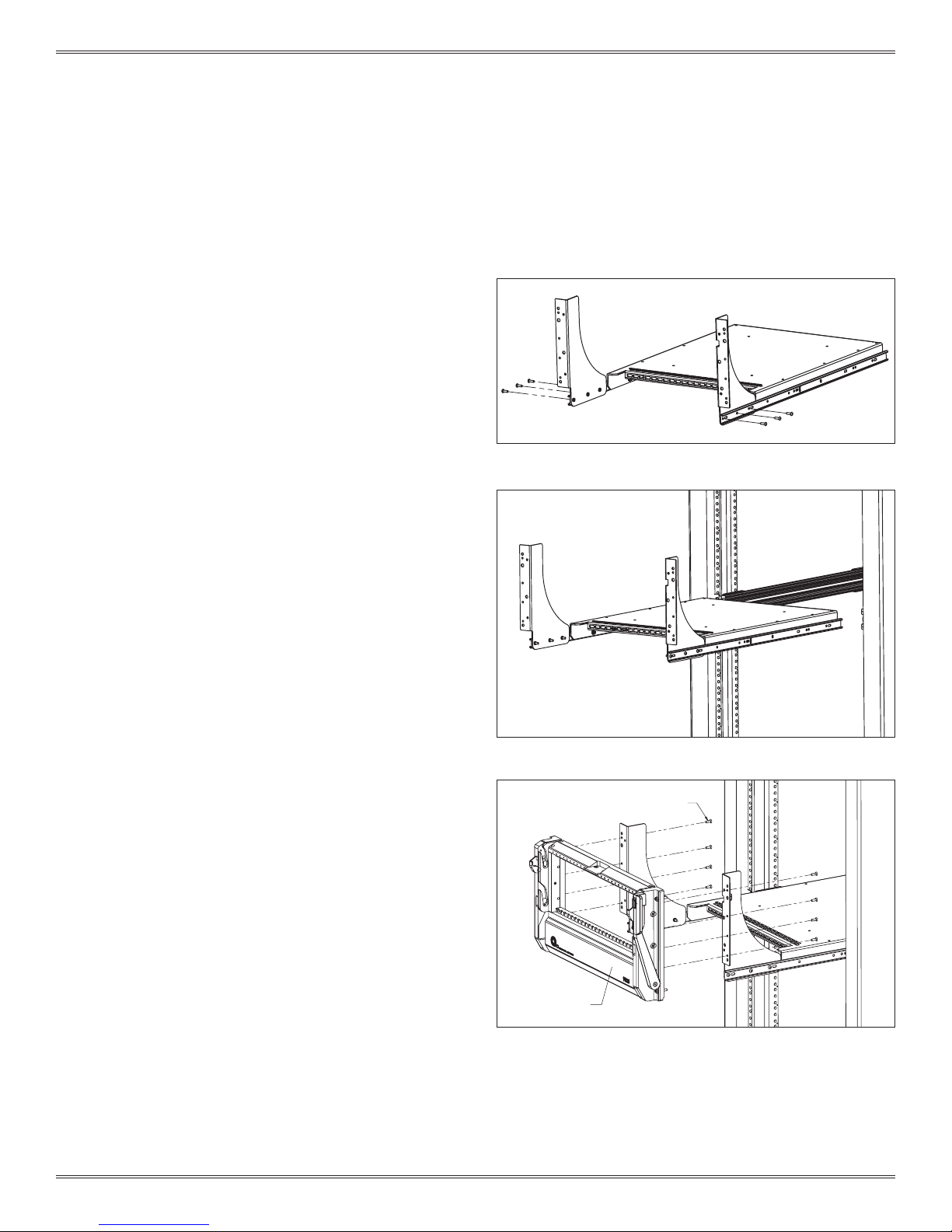
3. Attach the VHMF to the rack in the desired location using the
four 10-32 x 1” mounting screws (Figure C). Tighten screws in a
cross pattern to ensure even torque is applied.
4. When not in use, ensure that the receiver handle is closed and
the VHMF is in the closed position, secured with the two 8-32
screws (Figure D).
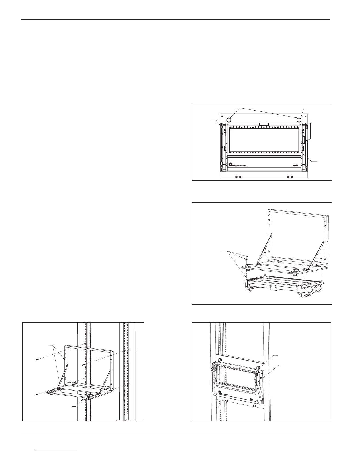
MOUNTING HOLE
TYP. 4 PLCS.
1/4 TURN LATCHES
VERTICAL HINGED
MOUNTING FRAME
RECEIVER
Figure A. Receiver assembled with Vertical Hinged Mounting
Frame.
MOUNTING HARDWARE
4 PLACES EACH
VERTICAL HINGED
MOUNTING FRAME
10-32 X 1" MOUNTING SCREWS
TYP. 4 PLCS.
Figure C. Attach the VHMF to the rack.
2-1 For more information visit vpc.com
Figure B. Attach receiver to VHMF using provided hardware.
8-32 SECURING SCREWS
RECEIVER HANDLE
(CLOSED POSITION)
Figure D. Screws secure receiver to rack when not in use.
10/4/13
9025 USER’S MANUAL: SECTION 3 VIRGINIA PANEL CORPORATION
SLIDE CONFIGURATION INSTALLATION - 9025TR
RECEIVER, 9025TR, 25 MODULE, WITH 20" PLATFORM • PART # 310 104 435
28" SLIDE KIT (FITS 26"– 30 " DEEP RACKS [660.4 – 762]) • PART # 310 113 451
30" SLIDE KIT (FITS 28" – 32" DEEP RACKS [711.2 – 812.8]) • PART # 310 113 411
36" SLIDE KIT (FITS 34" – 38" DEEP RACKS [863.6 – 965.2]) • PART # 310 113 500
Slides are used with the 9025 and 9025TR receiver. The receiver
includes a mounting bracket kit and hardware. Choose your slide kit
based on the distance from rail to rail and verify that the slides will not
interfere with the rack enclosure. Each kit will support 180 lbs.
TOOLS REQUIRED
Phillips Head Screwdriver
³/
Allen Wrench
32
DETERMINE YOUR SLIDE KIT
1. Measure dimension A to determine the proper slide kit, ensuring
the slide length does not exceed dimensions A + B (Figure A).
LOCATE AND MOUNT SLIDES
1. Determine an appropriate location in the rack to mount the
slides and receiver. Keep in mind that the cables connecting to
instrumentation not placed on the instrument bracket will need
to be long enough for the slides to fully extend without putting
tension on the cables.
NOTE: The “Cable Management” section of the Master catalog
can be used as a guide.
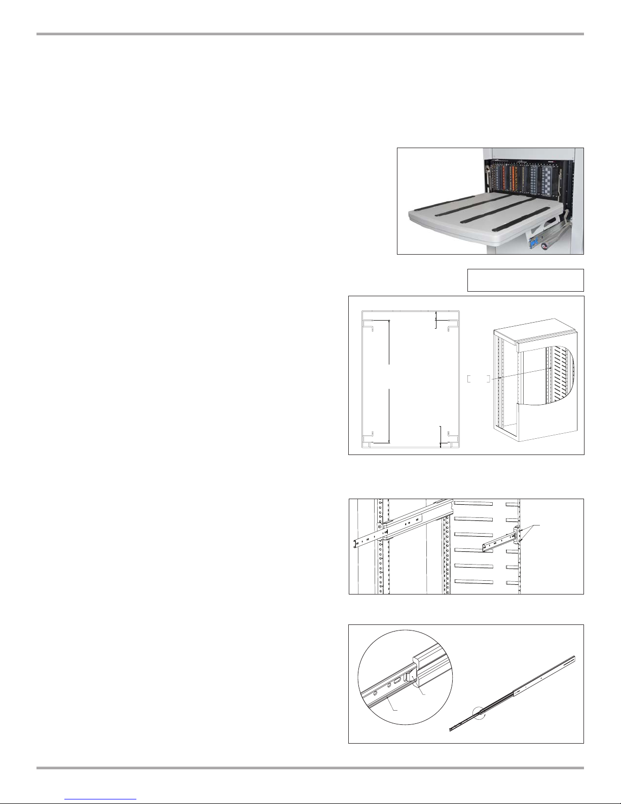
TOP VIEW
DIMENSION A
[749.3]
29.50
DIMENSION B
[50.8]
2.00
DIMENSION C
[31.75]
1.25
Dimensions shown: [millimeters]
inches
749.30
29.50
2. Install slides using manufacturer’s instructions. A hard copy is
included with the shipment (www.accur ide.com/Resources/
pdf/3507-r4-0309.pdf). Make sure the same position mounting
holes are used for each side of the front and back brackets. Do
not fully tighten down the 4 front and 4 rear mounting screws at
this time (Figure B).
4. Remove the innermost section of each slide by extending the slide
fully, depressing the tab, and continue extending the inner section
of the slide until it is free from the slide assembly (Figure C).
5. Install the instrument bracket and/or cable tray onto the inner
sections of the slide kit following the Instrument Bracket Installation
instructions and/or Cable Tray Installation instructions found in
Section 4.
Figure A. Dimensions of rack to measure for slide kit.
10-32 X 1" MOUNTING
SCREW
2 TYP. EACH SIDE
Figure B. Slides installed into rack.
SLIDE
RELEASE TAB
INNER SLIDE
A
3-1 For more information visit vpc.com
Figure C. Remove inner section of slide from assembly.
10/4/13
9025 USER’S MANUAL: SECTION 3 VIRGINIA PANEL CORPORATION
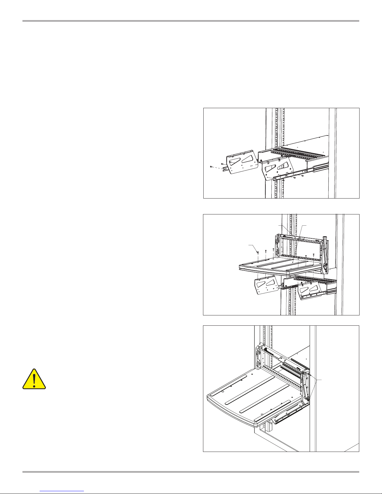
9025TR RECEIVER 9025TR PLATFORM
8-32 X .62"
FLAT HEAD SOCKET SCREW
TYP. 6 PLCS.
SLIDE CONFIGURATION INSTALLATION - 9025TR
RECEIVER, 9025TR, 25 MODULE, WITH 20" PLATFORM • PART # 310 104 435
28" SLIDE KIT (FITS 26"– 30 " DEEP RACKS [660.4 – 762]) • PART # 310 113 451
30" SLIDE KIT (FITS 28" – 32" DEEP RACKS [711.2 – 812.8]) • PART # 310 113 411
36" SLIDE KIT (FITS 34" – 38" DEEP RACKS [863.6 – 965.2]) • PART # 310 113 500
INSTALLATION - 9025TR
1. Install inner slides back into slide kit in the rack.
2. Attach the platform mounting anges to the inner slide rails
using the six 8-32 button head screws provided with the
receiver (Figure D). Do not fully tighten down the screws.
3. Install the 9025TR platform/receiver onto the platform
mounting anges with the six 8-32 screws (Figure E). Do not
fully tighten down the screws.
4. Pull the receiver out as far as possible. The slides will lock in
position. Push the blue tabs located on the middle section
of the slides. Apply pressure to push the receiver back in
toward the rack. The smaller inner slides move into the
middle section, which should not move. Push receiver until
it backs into the rack.
Figure D. Attach platform mounting anges to the inner slide
rails.
5. Secure the receiver to the rack using the captive 10- 32
screws (Figure F). Be sure to lift up on the platform slightly to
ensure an even engagement of the screws.
6. Fully tighten screws in this order:
- 6 8-32 platform mounting screws (as shown in Figure D).
- 6 8-32 button head platform mounting ange screws (as
shown in Figure C).
- 4 front slide mounting screws (from Slide Mounting
procedure, previous page).
- 4 rear slide mounting screws (from Slide Mounting
procedure, previous page).
7. Unscrew the 10-32 captive screws and slide the receiver
out.
ALWAYS SUPPORT THE RECEIVER AND PLATFORM
WITH THE MOST ROBUST (MIDDLE) SECTION OF
THE SLIDES.
To ensure proper support when extending the receiver and
table away from the rack, stop the receiver and platform at
approximately 6" from the rack. Reach around to the rear of the
receiver to the slides underneath on both sides. Manually extend
the middle section of the slides forward until fully underneath
the platform. The receiver and platform may then be extended
while holding this middle slide in place. If completed properly,
the middle section of the slides will remain underneath the
platform and offer the strongest support.
3-2 For more information visit vpc.com
Figure E. Install 9025TR into platform mounting anges.
CAPTIVE 10-32
PANHEAD SCREWS
TYP. EACH SIDE
Figure F. Secure the receiver to the rack with the captive 10-32
screws, taking care to lift up on the platform slightly to ensure
even engagement.
10/4/13
9025 USER’S MANUAL: SECTION 3 VIRGINIA PANEL CORPORATION
SLIDE CONFIGURATION INSTALLATION - 9025
RECEIVER, 9025, 25 MODULE, WITH SLIDE MOUNTING KIT • PART # 310 104 437
28" SLIDE KIT (FITS 26"– 30 " DEEP RACKS [660.4 – 762]) • PART # 310 113 451
30" SLIDE KIT (FITS 28" – 32" DEEP RACKS [711.2 – 812.8]) • PART # 310 113 411
36" SLIDE KIT (FITS 34" – 38" DEEP RACKS [863.6 – 965.2]) • PART # 310 113 500
Slides are used with the 9025 and 9025TR receiver. The receiver
includes a mounting bracket kit and hardware. Choose your slide kit
based on the distance from rail to rail and verify that the slides will not
interfere with the rack enclosure. Each kit will support 180 lbs.
TOOLS REQUIRED
Phillips Head Screwdriver
³/32 Allen Wrench
DETERMINE YOUR SLIDE KIT
1. Measure dimension A to determine the proper slide kit, ensuring
the slide length does not exceed dimensions A + B (Figure A).
LOCATE AND MOUNT SLIDES
1. Determine an appropriate location in the rack to mount the
slides and receiver. Keep in mind that the cables connecting to
instrumentation not placed on the instrument bracket will need
to be long enough for the slides to fully extend without putting
tension on the cables.
NOTE: The “Cable Management” section of the Master catalog
can be used as a guide.
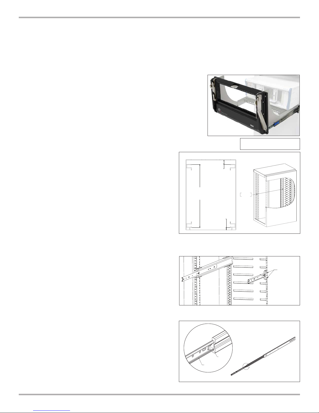
TOP VIEW
DIMENSION A
[749.3]
29.50
DIMENSION B
[50.8]
2.00
DIMENSION C
[31.75]
1.25
Dimensions shown: [millimeters]
inches
749.30
29.50
2. Install slides using manufacturer’s instructions. A hard copy is
included with the shipment (www.accur ide.com/Resources/
pdf/3507-r4-0309.pdf). Make sure the same position mounting
holes are used for each side of the front and back brackets. Do
not fully tighten down the 4 front and 4 rear mounting screws at
this time (Figure B).
4. Remove the innermost section of each slide by extending the slide
fully, depressing the tab, and continue extending the inner section
of the slide until it is free from the slide assembly (Figure C).
5. Install the instrument bracket and/or cable tray onto the inner
sections of the slide kit following the Instrument Bracket Installation
instructions and/or Cable Tray Installation instructions found in
Section 4.
Figure A. If dimension C exceeds 1" use the Rack Extender
Kit, Par t # 310 113 406.
10-32 X 1" MOUNTING
SCREW
2 TYP. EACH SIDE
Figure B. Slides installed into rack.
SLIDE
RELEASE TAB
INNER SLIDE
A
3-3 For more information visit vpc.com
Figure C. Remove inner section of slide from assembly.
10/4/13
9025 USER’S MANUAL: SECTION 3 VIRGINIA PANEL CORPORATION
SLIDE CONFIGURATION INSTALLATION - 9025
RECEIVER, 9025, 25 MODULE, WITH SLIDE MOUNTING KIT • PART # 310 104 437
28" SLIDE KIT (FITS 26"– 30" DEEP RACKS [660.4 – 762]) • PART # 310 113 451
30" SLIDE KIT (FITS 28 " – 32" DEEP RACKS [711.2 – 812.8]) • PART # 310 113 411
36" SLIDE KIT (FITS 34" – 38" DEEP RACKS [863.6 – 965.2]) • PART # 310 113 500
INSTALLATION - 9025
1. Attach each receiver mounting ange to the
appropriate slide using the provided three 8 -32 button
head screws per side. Ensure that the mounting surface
portion of the ange is directed toward the outside of
the overall assembly (Figure D).
2. Re-install the inner slide assembly into the rack by
aligning each inner slide with the slide assembly in the
rack (Figure E). With the inner section inser ted into the
center section of the slide assembly, push the mounting
anges toward the rack, collapsing the slides. It may be
necessary to depress the locking tabs, if the slides are
locked in the extended position.
Figure D. Be sure the mounting surface of the ange is facing out.
3. Pull the slide assembly out to enable access to the
mounting anges.
4. Using the provided eight 8-32 at head screws, attach
the receiver to the mounting anges (Figure F).
NOTE: When moving the rack or attaching an ITA, ensure the
slides are fully collapsed and receiver is secured to rack
with .190-32 UNF screws.
Figure E. If necessary, depress the locking tabs on the slides to
fully collapse the slide assembly.
8-32
FLAT HEAD SOCKET SCREW
TYP. 8 PLCS.
9025 RECEIVER
3-4 For more information visit vpc.com
Figure F.
10/4/13
 Loading...