


9025 USER’S MANUAL
TABLE OF CONTENTS
SECTION 1 RACK MOUNT CONFIGURATION
SECTION 2 VERTICAL HINGED MOUNTING FRAME CONFIGURATION
SECTION 3 SLIDE CONFIGURATION
SECTION 4 SLIDE CONFIGURATION ACCESSORIES
SECTION 5 TABLE TOP MOUNTING CONFIGURATION
SECTION 6 PLATFORM REMOVAL
SECTION 7 HANDLE REMOVAL AND REPOSITIONING
SECTION 8 MICROSWITCH REMOVAL AND INSTALLATION
SECTION 9 ITA ENCLOSURES
SECTION 10 ITA AND RECEIVER ENGAGEMENT
SEC T I O N 11 TROUBLESHOOTING AND PRECAUTIONARY NOTES
10/4/13
9025 USER’S MANUAL: SECTION 1 VIRGINIA PANEL CORPORATION
RACK MOUNT INSTALLATION
RECEIVER, 9025, 25 MODULE, SINGLE TIER • PART # 310 104 420
The 25 Module Receiver is designed to t into a standard 19” rack. It is
equipped with a locking handle to ensure your contacts are engaged. A
standa rd integrated microswitch (when wired to the test system) shuts off
power when the ITA disengages from the Receiver.
TOOLS REQUIRED
Phillips Head Screwdriver
INSTALLATION INSTRUCTIONS
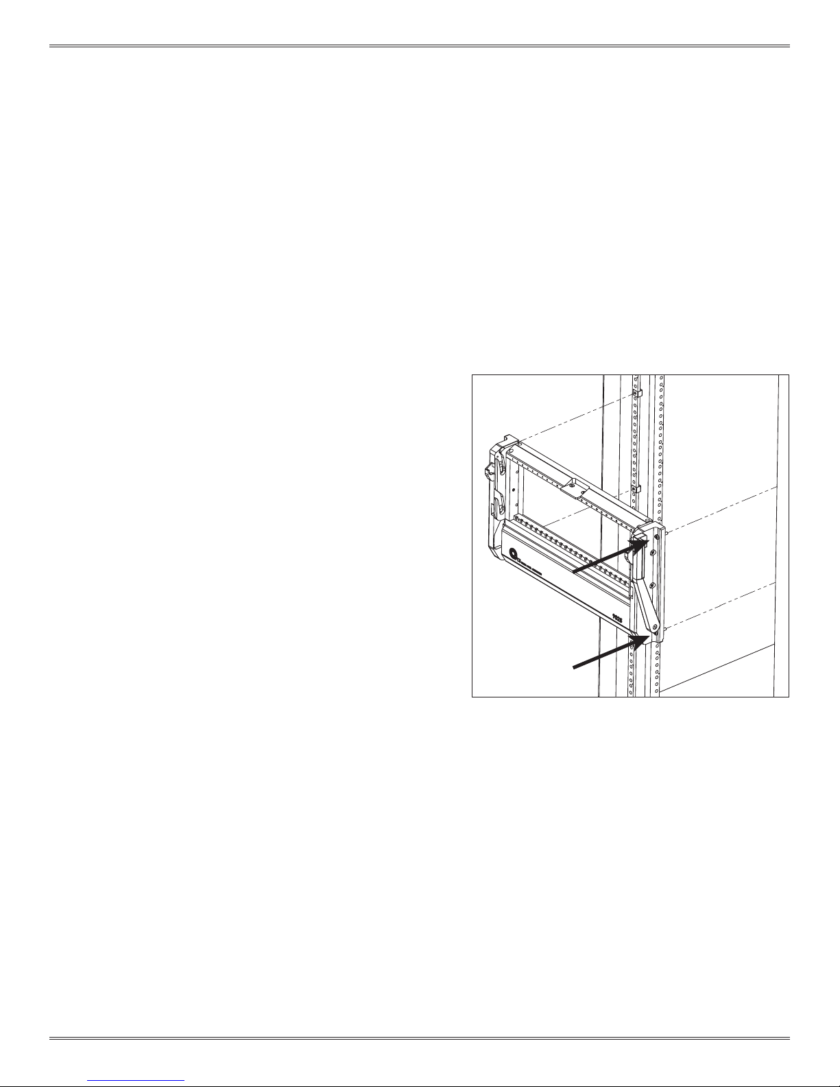
1. Install clip/cage nuts on rack, to correlate with mounting
holes and captive screws on receiver.
2. Place receiver up to clip/cage nuts on rack, making sure
they are aligned (Figure A).
3. Tighten captive screws in a cross pattern to ensure even
torque is applied.
1-1 For more information visit vpc.com
Figure A. Mounting 9025 Receiver.
10/4/13
9025 USER’S MANUAL: SECTION 2 VIRGINIA PANEL CORPORATION
VERTICAL HINGED MOUNTING FRAME INSTALLATION
8U HINGED MOUNTING FRAME • PART # 310 113 316
9U HINGED MOUNTING FRAME • PART # 310 113 320
RECEIVER, 9025, 25 MODULE, SINGLE TIER • PART # 310 104 420
The Vertical Hinged Mounting Frame allows the 9025 Receiver to hinge
down allowing access to instrumentation and wiring.
TOOLS REQUIRED
Phillips Head Screwdriver
³/
Allen Wrench
32
INSTALLATION INSTRUCTIONS
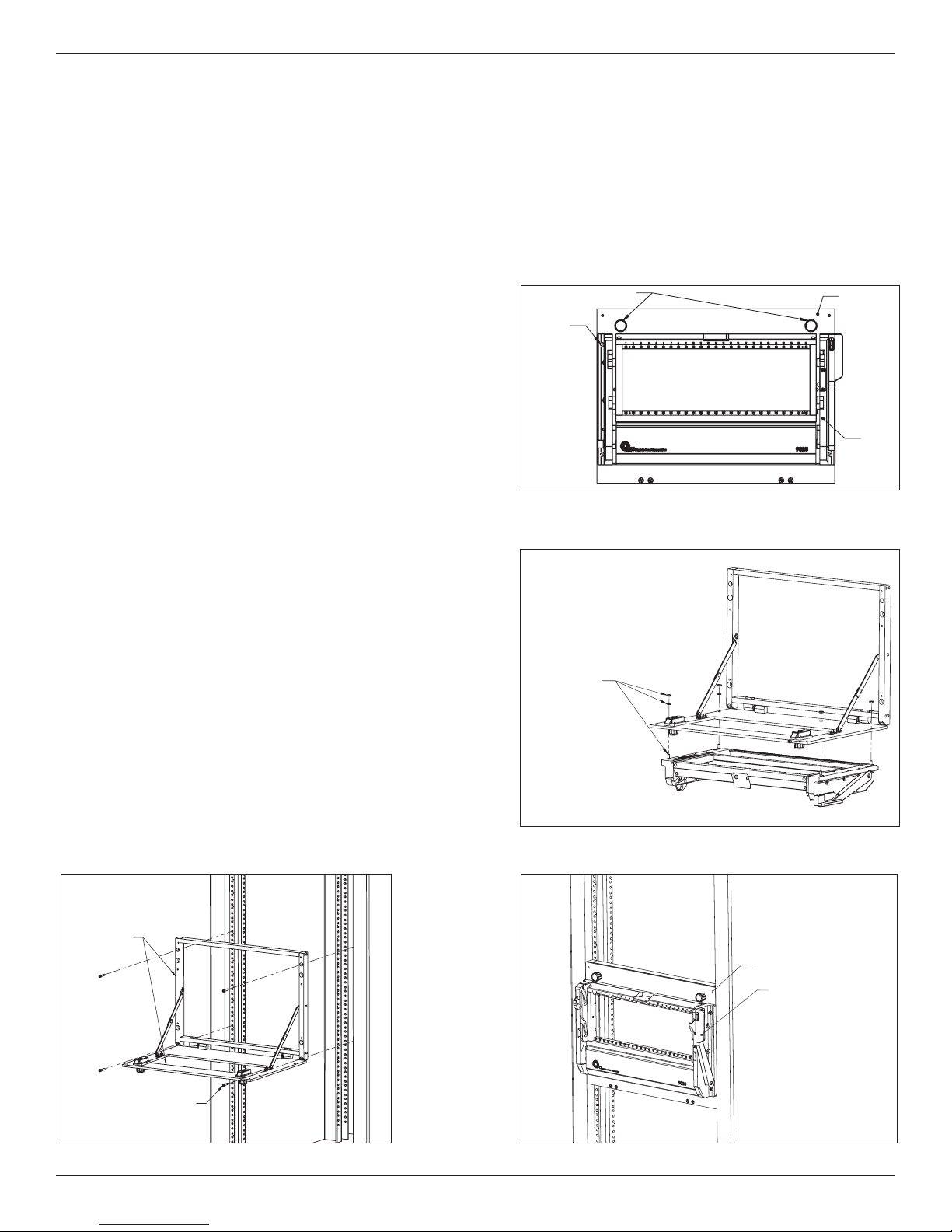
1. Using the 4 receiver mounting holes, attach the receiver to the
Vertical Hinged Mounting Frame (VHMF) with the 10-32 x 1”
captive screws, lock washers, and hex nuts included with the
VHMF (Figures A and B).
2. Determine an appropriate location in the rack to mount the
VHMF and receiver. Keep in mind that the cables connecting
to the receiver need to be long enough to allow the VHMF to
hinge down.
NOTE: The “Cable Management” section of the master catalog
and website can be used as a guide.
3. Attach the VHMF to the rack in the desired location using the
four 10-32 x 1” mounting screws (Figure C). Tighten screws in a
cross pattern to ensure even torque is applied.
4. When not in use, ensure that the receiver handle is closed and
the VHMF is in the closed position, secured with the two 8-32
screws (Figure D).
MOUNTING HOLE
TYP. 4 PLCS.
1/4 TURN LATCHES
VERTICAL HINGED
MOUNTING FRAME
RECEIVER
Figure A. Receiver assembled with Vertical Hinged Mounting
Frame.
MOUNTING HARDWARE
4 PLACES EACH
VERTICAL HINGED
MOUNTING FRAME
10-32 X 1" MOUNTING SCREWS
TYP. 4 PLCS.
Figure C. Attach the VHMF to the rack.
2-1 For more information visit vpc.com
Figure B. Attach receiver to VHMF using provided hardware.
8-32 SECURING SCREWS
RECEIVER HANDLE
(CLOSED POSITION)
Figure D. Screws secure receiver to rack when not in use.
10/4/13
9025 USER’S MANUAL: SECTION 3 VIRGINIA PANEL CORPORATION
SLIDE CONFIGURATION INSTALLATION - 9025TR
RECEIVER, 9025TR, 25 MODULE, WITH 20" PLATFORM • PART # 310 104 435
28" SLIDE KIT (FITS 26"– 30 " DEEP RACKS [660.4 – 762]) • PART # 310 113 451
30" SLIDE KIT (FITS 28" – 32" DEEP RACKS [711.2 – 812.8]) • PART # 310 113 411
36" SLIDE KIT (FITS 34" – 38" DEEP RACKS [863.6 – 965.2]) • PART # 310 113 500
Slides are used with the 9025 and 9025TR receiver. The receiver
includes a mounting bracket kit and hardware. Choose your slide kit
based on the distance from rail to rail and verify that the slides will not
interfere with the rack enclosure. Each kit will support 180 lbs.
TOOLS REQUIRED
Phillips Head Screwdriver
³/
Allen Wrench
32
DETERMINE YOUR SLIDE KIT
1. Measure dimension A to determine the proper slide kit, ensuring
the slide length does not exceed dimensions A + B (Figure A).
LOCATE AND MOUNT SLIDES
1. Determine an appropriate location in the rack to mount the
slides and receiver. Keep in mind that the cables connecting to
instrumentation not placed on the instrument bracket will need
to be long enough for the slides to fully extend without putting
tension on the cables.
NOTE: The “Cable Management” section of the Master catalog
can be used as a guide.
TOP VIEW
DIMENSION A
[749.3]
29.50
DIMENSION B
[50.8]
2.00
DIMENSION C
[31.75]
1.25
Dimensions shown: [millimeters]
inches
749.30
29.50
2. Install slides using manufacturer’s instructions. A hard copy is
included with the shipment (www.accur ide.com/Resources/
pdf/3507-r4-0309.pdf). Make sure the same position mounting
holes are used for each side of the front and back brackets. Do
not fully tighten down the 4 front and 4 rear mounting screws at
this time (Figure B).
4. Remove the innermost section of each slide by extending the slide
fully, depressing the tab, and continue extending the inner section
of the slide until it is free from the slide assembly (Figure C).
5. Install the instrument bracket and/or cable tray onto the inner
sections of the slide kit following the Instrument Bracket Installation
instructions and/or Cable Tray Installation instructions found in
Section 4.
Figure A. Dimensions of rack to measure for slide kit.
10-32 X 1" MOUNTING
SCREW
2 TYP. EACH SIDE
Figure B. Slides installed into rack.
SLIDE
RELEASE TAB
INNER SLIDE
A
3-1 For more information visit vpc.com
Figure C. Remove inner section of slide from assembly.
10/4/13
9025 USER’S MANUAL: SECTION 3 VIRGINIA PANEL CORPORATION
9025TR RECEIVER 9025TR PLATFORM
8-32 X .62"
FLAT HEAD SOCKET SCREW
TYP. 6 PLCS.
SLIDE CONFIGURATION INSTALLATION - 9025TR
RECEIVER, 9025TR, 25 MODULE, WITH 20" PLATFORM • PART # 310 104 435
28" SLIDE KIT (FITS 26"– 30 " DEEP RACKS [660.4 – 762]) • PART # 310 113 451
30" SLIDE KIT (FITS 28" – 32" DEEP RACKS [711.2 – 812.8]) • PART # 310 113 411
36" SLIDE KIT (FITS 34" – 38" DEEP RACKS [863.6 – 965.2]) • PART # 310 113 500
INSTALLATION - 9025TR
1. Install inner slides back into slide kit in the rack.
2. Attach the platform mounting anges to the inner slide rails
using the six 8-32 button head screws provided with the
receiver (Figure D). Do not fully tighten down the screws.
3. Install the 9025TR platform/receiver onto the platform
mounting anges with the six 8-32 screws (Figure E). Do not
fully tighten down the screws.
4. Pull the receiver out as far as possible. The slides will lock in
position. Push the blue tabs located on the middle section
of the slides. Apply pressure to push the receiver back in
toward the rack. The smaller inner slides move into the
middle section, which should not move. Push receiver until
it backs into the rack.
Figure D. Attach platform mounting anges to the inner slide
rails.
5. Secure the receiver to the rack using the captive 10- 32
screws (Figure F). Be sure to lift up on the platform slightly to
ensure an even engagement of the screws.
6. Fully tighten screws in this order:
- 6 8-32 platform mounting screws (as shown in Figure D).
- 6 8-32 button head platform mounting ange screws (as
shown in Figure C).
- 4 front slide mounting screws (from Slide Mounting
procedure, previous page).
- 4 rear slide mounting screws (from Slide Mounting
procedure, previous page).
7. Unscrew the 10-32 captive screws and slide the receiver
out.
ALWAYS SUPPORT THE RECEIVER AND PLATFORM
WITH THE MOST ROBUST (MIDDLE) SECTION OF
THE SLIDES.
To ensure proper support when extending the receiver and
table away from the rack, stop the receiver and platform at
approximately 6" from the rack. Reach around to the rear of the
receiver to the slides underneath on both sides. Manually extend
the middle section of the slides forward until fully underneath
the platform. The receiver and platform may then be extended
while holding this middle slide in place. If completed properly,
the middle section of the slides will remain underneath the
platform and offer the strongest support.
3-2 For more information visit vpc.com
Figure E. Install 9025TR into platform mounting anges.
CAPTIVE 10-32
PANHEAD SCREWS
TYP. EACH SIDE
Figure F. Secure the receiver to the rack with the captive 10-32
screws, taking care to lift up on the platform slightly to ensure
even engagement.
10/4/13
9025 USER’S MANUAL: SECTION 3 VIRGINIA PANEL CORPORATION
SLIDE CONFIGURATION INSTALLATION - 9025
RECEIVER, 9025, 25 MODULE, WITH SLIDE MOUNTING KIT • PART # 310 104 437
28" SLIDE KIT (FITS 26"– 30 " DEEP RACKS [660.4 – 762]) • PART # 310 113 451
30" SLIDE KIT (FITS 28" – 32" DEEP RACKS [711.2 – 812.8]) • PART # 310 113 411
36" SLIDE KIT (FITS 34" – 38" DEEP RACKS [863.6 – 965.2]) • PART # 310 113 500
Slides are used with the 9025 and 9025TR receiver. The receiver
includes a mounting bracket kit and hardware. Choose your slide kit
based on the distance from rail to rail and verify that the slides will not
interfere with the rack enclosure. Each kit will support 180 lbs.
TOOLS REQUIRED
Phillips Head Screwdriver
³/32 Allen Wrench
DETERMINE YOUR SLIDE KIT
1. Measure dimension A to determine the proper slide kit, ensuring
the slide length does not exceed dimensions A + B (Figure A).
LOCATE AND MOUNT SLIDES
1. Determine an appropriate location in the rack to mount the
slides and receiver. Keep in mind that the cables connecting to
instrumentation not placed on the instrument bracket will need
to be long enough for the slides to fully extend without putting
tension on the cables.
NOTE: The “Cable Management” section of the Master catalog
can be used as a guide.
TOP VIEW
DIMENSION A
[749.3]
29.50
DIMENSION B
[50.8]
2.00
DIMENSION C
[31.75]
1.25
Dimensions shown: [millimeters]
inches
749.30
29.50
2. Install slides using manufacturer’s instructions. A hard copy is
included with the shipment (www.accur ide.com/Resources/
pdf/3507-r4-0309.pdf). Make sure the same position mounting
holes are used for each side of the front and back brackets. Do
not fully tighten down the 4 front and 4 rear mounting screws at
this time (Figure B).
4. Remove the innermost section of each slide by extending the slide
fully, depressing the tab, and continue extending the inner section
of the slide until it is free from the slide assembly (Figure C).
5. Install the instrument bracket and/or cable tray onto the inner
sections of the slide kit following the Instrument Bracket Installation
instructions and/or Cable Tray Installation instructions found in
Section 4.
Figure A. If dimension C exceeds 1" use the Rack Extender
Kit, Par t # 310 113 406.
10-32 X 1" MOUNTING
SCREW
2 TYP. EACH SIDE
Figure B. Slides installed into rack.
SLIDE
RELEASE TAB
INNER SLIDE
A
3-3 For more information visit vpc.com
Figure C. Remove inner section of slide from assembly.
10/4/13
9025 USER’S MANUAL: SECTION 3 VIRGINIA PANEL CORPORATION
SLIDE CONFIGURATION INSTALLATION - 9025
RECEIVER, 9025, 25 MODULE, WITH SLIDE MOUNTING KIT • PART # 310 104 437
28" SLIDE KIT (FITS 26"– 30" DEEP RACKS [660.4 – 762]) • PART # 310 113 451
30" SLIDE KIT (FITS 28 " – 32" DEEP RACKS [711.2 – 812.8]) • PART # 310 113 411
36" SLIDE KIT (FITS 34" – 38" DEEP RACKS [863.6 – 965.2]) • PART # 310 113 500
INSTALLATION - 9025
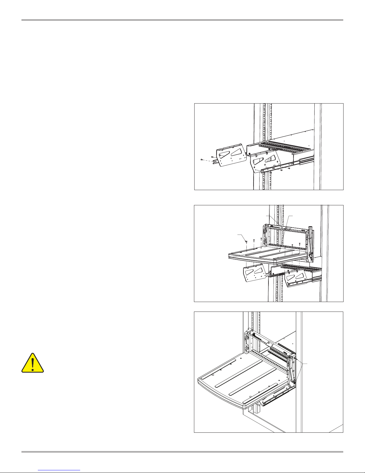
1. Attach each receiver mounting ange to the
appropriate slide using the provided three 8 -32 button
head screws per side. Ensure that the mounting surface
portion of the ange is directed toward the outside of
the overall assembly (Figure D).
2. Re-install the inner slide assembly into the rack by
aligning each inner slide with the slide assembly in the
rack (Figure E). With the inner section inser ted into the
center section of the slide assembly, push the mounting
anges toward the rack, collapsing the slides. It may be
necessary to depress the locking tabs, if the slides are
locked in the extended position.
Figure D. Be sure the mounting surface of the ange is facing out.
3. Pull the slide assembly out to enable access to the
mounting anges.
4. Using the provided eight 8-32 at head screws, attach
the receiver to the mounting anges (Figure F).
NOTE: When moving the rack or attaching an ITA, ensure the
slides are fully collapsed and receiver is secured to rack
with .190-32 UNF screws.
Figure E. If necessary, depress the locking tabs on the slides to
fully collapse the slide assembly.
8-32
FLAT HEAD SOCKET SCREW
TYP. 8 PLCS.
9025 RECEIVER
3-4 For more information visit vpc.com
Figure F.
10/4/13

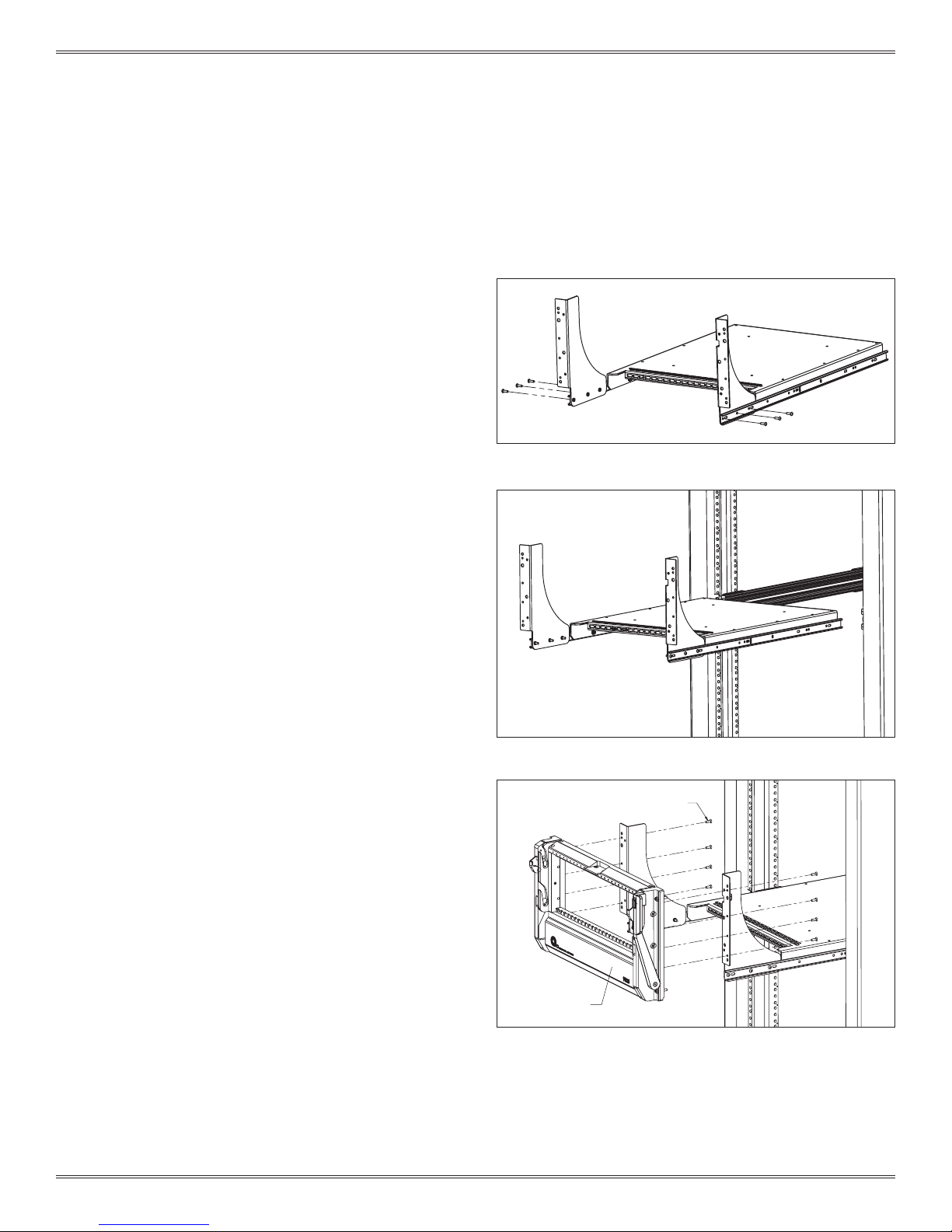
9025 USER’S MANUAL: SECTION 4 VIRGINIA PANEL CORPORATION
INSTRUMENT BRACKET INSTALLATION
PART # 310 113 453
The instrument bracket mounts to the inner slide and provides
maintenance access to the chassis and the instruments.
NOTE: This instrument bracket kit does not work with the 20”
or 24” slide kits.
TOOLS REQUIRED
5
/32 Allen Wrench
Phillips Head Screwdriver
INSTALLATION
1. Depress the blue tab on the inner slide and remove from
outer slide.
2. Attach one of the inner slides to the instrument bracket
using two 8-32 button head screws in the front two holes
(Figure A). Install the third 8 -32 button head screw in the rear
hole of the inner slide and instrument bracket.
3. Attach the remaining inner slide to the other side of the
instrument bracket.
Continued on next page...
FRONT TWO HOLES
ALIGN UNIVERSALLY
ON ALL SLIDE LENGTHS
Figure A. The front two holes on the instrument bracket align with
the front two holes on any length slide kit. The third hole alignment may differ depending on which slide kit you are using.
Shown here, 30” slide k it, part # 310 113 411.
4-1 For more information visit vpc.com
Figure B. The slots on the instrument brackets are designed to
accept a strap should you want to secure your chassis.
10/4/13

9025 USER’S MANUAL: SECTION 4 VIRGINIA PANEL CORPORATION
INSTRUMENT BRACKET INSTALLATION
PART # 310 113 453
4. Reinstall the inner slides.
• Slide the left mid-section of the slide all the way out, you will
feel it lock into position.
• Feed the matching inner slide into position and ensure the
inner section rides into place with the roller bearings seated
into the groove.
• Push the inner slide in about 6-8 inches and then pull out the
right side. Slide the track of the mid-section over the right side
of the inner slide.
• Pull the slide out until the position matches the left side.
• Reach to the back of the middle slides and release the spring
locking mechanism (Figure C).
NOTE: At this time, both sides should be partially installed when it
will no longer proceed into the rack because the support tab on
the instrument brackets will hit the slide mounting bracket.
5. Rotate both instrument brackets inward so the support tabs
can pass the mounting brackets. Continue to push (install slides
simultaneously) into position. Remember to push the blue tabs
to allow the inner slide to continue to travel into the middle slide
section.
NOTE: The middle section will not go into the outer section until
the inner section has been fully installed into the middle section.
6. Tighten the slide mounting screws.
MAKE SURE ALL SCREW HEADS HAVE BEEN SECURELY
TIGHTENED. ONLY USE 8-32 BUTTON HEAD SCREWS.
Figure C. Spring-locking mechanism.
4-2 For more information visit vpc.com
10/4/13

9025 USER’S MANUAL: SECTION 4 VIRGINIA PANEL CORPORATION
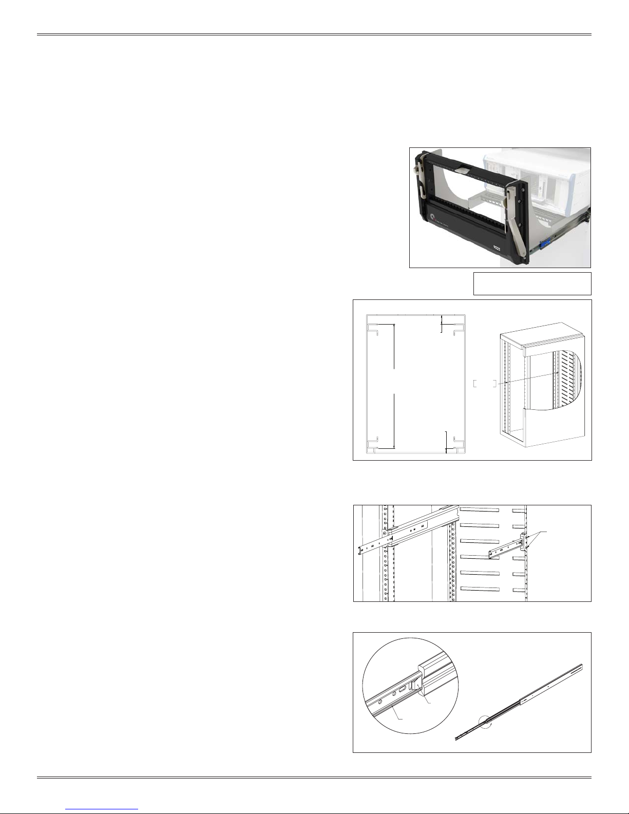
KEYBOARD TRAY KIT INSTALLATION
PART # 310 113 439
The Keyboard Tray Kit mounts below the platform on
the slide-mounted 9025TR receiver. The kit includes a
keyboard with touchpad and 72" long USB connector,
keyboard tray, and 12" slides.
TOOLS REQUIRED
3
32
/
Allen Wrench
28.4
[721.36]
13.0
[330.2]
12 INCH SLIDE
MOVEMENT
13.3
[337.82]
MOUNTING BRACKET, RIGHTMOUNTING BRACKET, LEFT
USB KEYBOARD
CONNECTOR.
12 INCH SLIDES
RUBBER GROMMET
KEYBOARD WITH TOUCHPAD
KEYBOARD TRAY
1.2
[30.48]
Figure A. Keyboa rd Tray Kit, Part # 310 113 439, includes components listed above and
mounting hardware.
4-3 For more information visit vpc.com
Dimensions shown: [millimeters]
inches
10/4/13
9025 USER’S MANUAL: SECTION 4 VIRGINIA PANEL CORPORATION
BOTTOM VIEW
BOTTOM VIEW
KEYBOARD TRAY KIT INSTALLATION
PART # 310 113 439
INSTRUCTIONS
1. Attach the keyboard mounting brackets to the existing
platform mounting brackets using with the supplied
8-32 at head screws, nuts, and lock washers to secure
the keyboard mounting brackets (Figure B).
2. Use six of the 8-32 x .38 button head screws to attach
th e 12" keyboard kit slides to the inner side of the
keyboard brackets. The manufacturer stamped
identication on the slides should be placed toward
the rack. Fully extend the keyboard slides to access the
hole locations. Hole locations are shown in Figure C.
3. Insert the keyboard into the keyboard tray. Wrap the
plastic strain relief around the cable near the back of
the keyboard and press into the hole provided on the
keyboard tray.
4. Fully extend the 12” slides and mount the keyboard
tray (Figure D). The different hole patterns allow for
variations in the overall extension of the keyboard tray.
SUPPLIED 8-32 SCREW,
LOCKING WASHER, AND NUT
PLATFORM MOUNTING BRACKET
MOUNTING BRACKET, LEFT
Figure B. Orient the keyboard mounting brackets to align with the three
screws that extend beyond the platform mounting bracket.
4-4 For more information visit vpc.com
SELF-LOCKING FASTENERS
Figure C. Fully extend the keyboard slides to access the mounting holes
for the self-locking fasteners.
Figure D. Floating, self-locking fasteners in the keyboard mounting
brackets prevent the screws from backing out. You will notice the snug
t when tightening the screws.
10/4/13

9025 USER’S MANUAL: SECTION 4 VIRGINIA PANEL CORPORATION
CABLE TRAY INSTALLATION
PART # 310 113 424
The cable tray is used for strain relief and cable management.
The horizontal and vertical anges provide tie down options that
allow you to bend and route your cables where you want and also
present a secure and reliable way to protect your investment.
NOTE: The cable tray does not work with the 20” or 24” slide kits or
the instrument bracket kit with strain relief.
TOOLS REQUIRED
3
32
/
Allen Wrench
INSTRUCTIONS
1. Loosen the slide mounting screws by one turn.
2. Depress the blue tabs and remove the inner slides.
3. Attach the cable tray to the slides with 8 -32 screws (Figure A).
Figure A. The angled side of the cable tray should face the receiver.
4. Install the inner slides and cable tray assembly into the rack. See Instrument Bracket Installation instructions for more detail.
5. Tighten the slide mounting screws.
4-5 For more information visit vpc.com
10/4/13

9025 USER’S MANUAL: SECTION 4 VIRGINIA PANEL CORPORATION
492.76
TABLETOP CONFIGURATION
RECEIVER, 9025TR, 25 MODULE • PART # 310 104 436
The 9025TR for tabletop applications is shipped with a rear
cover to protect receiver side wiring and a “skirt” to allow
sufcient rotation of the handle.
PERMANENT TABLETOP MOUNTING
1. Prepare the mounting surface using the dimensions provided in Figures A and B.
2. Secure the receiver skirt to the mounting sur face with the provided ¼ -20 x 1.00 screws, washers and nuts.
3. Use the ³/32 Allen wrench with the provided #8 -32 screws and washers to attach the included rear cover to the receiver.
4. Secure the rear cover to the mounting surface with the provided 10 -32 x .375 screws, washers and nuts (Figure B).
19.40
368.30
14.50
184.15
7.25
314.33
12.38
219.08
8.63
123.83
4.88
Figure A. Receiver without Rear Cover Installed. Drill 0.257”
[6.53 mm] minimum thru holes.
4-6 For more information visit vpc.com
11.43
.45
37.19
1.46
197.76
7.79
197.76
7.79
Figure B. Receiver with Rear Cover Installed. Drill 0.196”
[4.98 mm] minimum thru holes.
Dimensions shown: [millimeters]
inches
37.19
1.46
10/4/13

9025 USER’S MANUAL: SECTION 5 VIRGINIA PANEL CORPORATION
8-32 x .625" PLATFORM
MOUNTING SCREWS
PLATFORM REMOVAL AND INSTALLATION
RECEIVER, 9025TR, 25 MODULE, WITH 20” PLATFORM • PART # PART # 310 104 435
The platform is removable to allow easier pack ing and
moving of the instrument rack.
TOOLS REQUIRED
5
/32 Ball End Allen Wrench or Ball Driver
Phillips Head Screwdriver
Zip Ties
REMOVAL INSTRUCTIONS
1. Secure receiver to rack using the captive 10-32 mounting
screws (Figure A).
2. Remove any optional accessories including keyboard tray,
leg kit, and instrument bracket.
3. With the receiver secured to the rack, remove the six 8-32
mounting screws from the bottom of the 9025TR to remove
the platform (Figure B).
4. Remove the 8-32 screws that attach the platform brackets
to the slides. The platform will now be free from the receiver
and slides. The platform brackets do not need to be
removed from the platform for transportation.
5. To secure the slides for transport, return the slides to the
closed position and use zip tie to secure the 3 sections of
each slide.
INSTRUMENT BRACKET
10-32 X 1" MOUNTING SCREW
TYP. EACH SIDE
KEYBOARD
TRAY KIT
Figure A. The platform can be removed from the receiver only after
the receiver has been secured to the rack.
5-1 For more information visit vpc.com
Figure B. The six mounting screws must be removed from the
receiver before the platform can be removed.
10/4/13

9025 USER’S MANUAL: SECTION 5 VIRGINIA PANEL CORPORATION
PLATFORM BRACKET
8-32 X .50" BRACKET MOUNTING
SCREWS TYP.
9025TR PLATFORM
PLATFORM REMOVAL AND INSTALLATION
INSTALLATION INSTRUCTIONS
1. Remove the zip ties used to secure the slides.
2. Attach the platform with brackets to the slides using
six 8 -32 mounting screws (Figure C).
3. Slide the platform to the closed position and install
the six 8-32 mounting screws to attach the platform
to the 9025TR receiver.
4. Re-install any optional accessories.
5. Once the platform has been re-attached to the
9025TR and the slides, remove the captive 10-32
mounting screws shown in Figure A.
Figure C. The brackets will be securely attached to the slides after
the mounting screws are installed.
5-2 For more information visit vpc.com
10/4/13

9025 USER’S MANUAL: SECTION 6 VIRGINIA PANEL CORPORATION
MICRO-SWITCH REMOVAL AND INSTALLATION
PART # 310 113 200
A microswitch is used in the 90 Series/VXI receiver s
to determine the presence (or absence) of an ITA
engaged in the system. It is usually congured so that
power to the interface is turned off when there is no ITA
present. An integrated microswitch is standard on the
25 and 50 module receivers.
TOOLS REQUIRED
Phillips Head Screwdriver
REMOVAL INSTRUCTIONS
1. Disengage the ITA from the receiver (remove the ITA completely).
2. With the receiver handle still in the open position (handle is down), unscrew the two plate retaining screws (using a Phillips
screwdr iver) that are located immediately below the top right engaging mechanism/slot - this will expose the microswitch.
3. Remove the necessar y modules so that the microswitch retaining screws may be accessed.
4. Unscrew the retaining screws (using a Phillips screwdr iver), removing each as they are loosened (caution should be used so that the
screw(s) do not fall into the system).
5. Carefully remove the microswitch for continuity testing.
For microswitch installation, repeat steps 1 - 5 in reverse order.
AS WITH ALL ELECTRICAL SYSTEMS - DISCONNECT
ALL ELECTRICAL SUPPLIES TO THE SYSTEM PRIOR TO
REMOVAL OF THE MICROSWITCH.
6-1 For more information visit vpc.com
10/4/13

9025 USER’S MANUAL: SECTION 7 VIRGINIA PANEL CORPORATION
ITA ENCLOSURE
ENCLOSURE, 25 MODULE, HINGED COVER PLATE, 4” DEEP • PART # 410 112 198
ENCLOSURE, 25 MODULE, HINGED COVER PLATE, 8” DEEP • PART # 410 112 273
ITA, 9025, 25 MODULE, SINGLE TIER • PART # 410 104 111
The 9025 Enclosure is available to meet your testing needs. Custom
enclosures are also available if the standard one is not applicable
to your test system.
TOOLS REQUIRED
3 mm Allen Wrench
Phillips Head Screwdriver
25.40
1.00
*
164.85
Figure A. *Enclosures must be ush with the bottom of the ITA frame to ensure the proper function of the 9025TR. The width
may grow with customer needs as long as the extended width is offset to the side opposite the engagement handle. There
is no limit to the height of the enclosure.
7-1 For more information visit vpc.com
6.49
Dimensions shown: [millimeters]
inches
10/4/13

9025 USER’S MANUAL: SECTION 8 VIRGINIA PANEL CORPORATION
HANDLE REMOVAL AND REPOSITIONING
RECEIVER, 9025TR, 25 MODULE, WITH 20” PLATFORM • PART # 310 104 420
The 9025TR receiver handle requires approximately 90° of counter-
clock wise travel for engagement and 90° of clock wise travel for
disengagement of the ITA. This handle is removable and adjustable
to accommodate different mounting conguration requirements
and for transport purposes.
TOOLS REQUIRED
3
/32 Allen Wrench
ROTATION INSTRUCTIONS
1. Remove the handle screw with a 3/32 Allen wrench.
2. Remove the handle and reposition in 90˚ increments (Figure A).
3. Replace the screw and tighten until the handle is secured tightly.
REPOSITIONING INSTRUCTIONS
1. Using the 3/32 Allen wrench, remove the handle screw and handle
(Figure B).
2. Using the 3/32 Allen wrench, remove the screw and handle washer on
the left side of the receiver (Figure B).
3. Install the handle into the left side hole at the preferred 90° position
(Figure C).
4. Replace the screw and handle washer into the cavit y on right side of
the receiver (Figure C).
HANDLE WASHER
SCREW
HANDLE CAN BE LOOSENED AND
ROTATED IN 90 DEGREE INCREMENTS
489.97
19.29
553.47
21.79
Figure A. 9025TR Receiver handle can be rotated in
90 degree increments to support test station set up
needs.
Figure B. Remove handle from standard right side. Figure C. Install handle on left side.
8-1 For more information visit vpc.com
OFFSET LINK
OFFSET LINK
Dimensions shown: [millimeters]
inches
10/4/13

9025 USER’S MANUAL: SECTION 9 VIRGINIA PANEL CORPORATION
13
O
D
U
L
E
P
O
S
I
T
I
O
N
M
I
O
P
E
L
U
D
O
M
O
12
I
T
S
N
O
N
O
I
T
I
S
O
P
E
L
U
D
M
251
N
O
I
T
I
S
O
P
E
L
U
D
O
M
4
N
O
I
T
I
S
O
P
E
L
U
D
O
M
6
N
O
I
T
I
S
O
P
E
L
U
D
O
M
I
T
I
7
O
M
O
D
U
L
E
P
O
S
N
I
O
N
18
O
D
U
L
E
P
O
S
I
T
M
15
I
T
I
S
O
P
E
L
U
D
O
M
N
O
16
I
T
I
S
O
P
E
L
U
D
O
M
N
O
17
I
T
I
S
O
P
E
L
U
D
O
M
N
O
M
O
D
U
L
E
P
O
S
I
T
I
O
N
19
M
O
D
U
L
E
P
O
S
I
T
I
O
N
20
M
O
D
U
L
E
P
O
S
I
T
I
O
N
21
M
O
D
U
L
E
P
O
S
I
T
I
O
N
23
M
O
D
U
L
E
P
O
S
I
T
I
O
N
24
O
N
O
I
T
I
S
O
P
E
L
U
D
M
22
L
U
D
O
M
9
N
O
I
T
I
S
O
P
E
D
O
M
N
O
I
T
I
S
O
P
E
L
U
11M10
O
I
T
I
S
O
P
E
L
U
D
O
N
U
O
M
3
N
O
I
T
I
S
O
P
E
L
D D
U
L
E
P
O
S
I
T
I
O
N
5
M
O
O
N
M
O
D
U
L
E
P
O
S
I
T
I
14
M
2
N
O
I
T
I
S
O
P
E
L
U
D
O
N
D
U
L
E
P
O
S
I
T
I
O
8
M
O
M
D
U
L
E
P
O
S
I
T
I
O
N
23
O
D
L
E
P
O
S
I
T
I
O
N
14
O
U
M
13
N
O
I
T
I
S
O
P
E
L
U
D
O
M
12
N
O
I
T
I
S
O
P
E
L
U
D
O
M
11
N
O
I
T
I
S
O
P
E
L
U
D
O
M
10
N
O
I
T
I
S
O
P
E
L
U
D
O
M
I
I
O
N
M
O
D
U
L
E
P
O
S
6T8
O
M
O
D
U
L
E
P
O
S
I
T
I
N
7
S
O
P
E
L
U
D
O
M
N
O
I
T
I
M
L
E
P
O
S
I
T
I
O
N
4
O
D
U
M
L
E
P
O
S
I
T
I
O
N
3
O
D
U
9
N
O
I
T
I
S
O
P
E
L
U
D
O
M
D
M
L
E
P
O
S
I
T
I
O
N
17
O
U
M
O
D
U
L
E
P
O
S
I
T
I
O
N
25
O
21
N
O
I
T
I
S
O
P
E
L
U
D
MM
U
L
E
P
O
S
I
T
I
O
N
15
O
D
24
O
M
O
D
U
L
E
P
O
S
I
T
I
N
M
O
D
U
L
E
P
O
S
I
T
I
O
N
22
O
16
N
O
I
T
I
S
O
P
E
L
U
D
M
M
U
L
E
P
O
S
I
T
I
O
N
2
O
D
M
19
N
O
I
T
I
S
O
P
E
L
U
D
O
U
D
O
18
N
O
I
T
I
S
O
P
E
L
MM
O
D
U
L
E
P
O
S
I
T
I
O
N
20
N
5
I
T
I
S
O
P
E
L
U
D
O
M
O
M
O
D
U
L
E
P
O
S
I
T
I
O
N
1
ITA & RECEIVER ENGAGEMENT
Prior to engaging an ITA with the receiver for the rst time, ensure all modules (ITA and receiver) are properly installed. This involves
inspection of modules to ensure proper mounting and to verify module positioning. Module positions are shown in Figure A. Modules
must be installed such that Pin 1 of each respective mating receiver and ITA module pair are adjacent. VPC recommends that Pin 1
always be positioned to the left in the receiver and ITA frames. All ITA modules must match the respective receiver modules. It is crucial
for all modules to be installed properly.
Figure A. 9025 Receiver and ITA.
1. The receiver should be checked for any foreign objects that may interfere with engagement.
2. After inspection, the ITA is ready for engagement with the receiver. The ITA may be placed onto the receiver platform and properly
positioned relative to the receiver guide pins. Ensure that the ITA roller bearings are aligned with the receiver slide openings when the
receiver handle is in the open position.
3. Carefully rotate the handle for ward to actuate the receiver slide engagement mechanisms, which will draw the ITA into engagement
position with the receiver. Once the handle reaches a positive stop at the end of its travel and latches into place, the modules are
engaged.
4. Upon completing use of the ITA, rotate the receiver handle to the open position, remove the ITA, reinstall the receiver protective cover
and rotate the handle to the closed position.
5. Always protect the contacts when the system is not in use. The receiver contacts are protected when either the ITA or receiver
protective cover is engaged. VPC recommends use of both receiver and ITA protective covers to avoid potential contact damage.
IMPROPER INSTALLATION WILL DAMAGE THE
MODULES, AND POSSIBLY THE ITA AND/OR
RECEIVER.
IN THE EVENT OF COMPLICATIONS, A TRAINED
TECHNICIAN SHOULD BE NOTIFIED IMMEDIATELY
TO AVOID ANY DAMAGE TO THE SYSTEM. THIS
APPLIES TO ANY DIFFICULTIES THAT MAY BE
EXPERIENCED DURING ENGAGEMENT.
9-1 For more information visit vpc.com
10/4/13

9025 USER’S MANUAL: SECTION 10 VIRGINIA PANEL CORPORATION
TIGHTEN SCREW TO
DESIRED SETTING WITH
FLAT HEAD SCREWDRIVER.
TIGHTEN SCREW TO
RIGHT HANDLE LEFT HANDLE
DESIRED SETTING WITH
FLAT HEAD SCREWDRIVER.
TROUBLESHOOTING
ITA frame is not lined up when in the process of engagement with receiver
• This may indicate that the ITA is out of alignment or that a module is not mating with its intended module.
• Remove and inspect the ITA for alignment,
• Check for foreign objects/tools.
• Inspect the matching of modules -power ITA module to mate with power receiver module, etc.
Excessive force is needed to engage the handle
• With a typical contact load, approximately 35lbs force is needed to engage the handle. Consult with a VPC application engineer
for detailed contact loading information.
• If excessive force is required, this may indicate that the ITA is out of alignment or that a module is not mating with its intended
module.
• Remove and inspect the ITA for alignment. Contact VPC – unauthor ized user adjustments to system will void the warranty.
• Check for foreign objects/tools.
• Contact damage may provide enough resistance to notice. Upon replacing a contact in the ITA, the mating contact on the receiver
side should also be inspected and replaced if necessar y.
• Verify the orientation of the receiver and ITA modules.
• Inspect the matching modules - power ITA module to mate with power receiver module, etc.
ITA will not engage with the receiver after diagnosing the above problems
• Contact Vi rginia Panel Corporation – unauthorized user adjustments to the system will void the warranty.
No continuity upon engagement
• When replacing an ITA contact, the mating contact on the receiver side should also be inspected and replaced if necessary.
• Check wiring and replace if necessary.
• Contact not secured in module.
• A contact may be damaged. Visually check all contacts for damage to potentially isolate damaged pin prior to checking for
continuity with a multi-meter.
A “short ” in the wiring upon engagement
• A damaged contact(s) may cause high resistance. Upon replacing a contact in the ITA, the mating contact on the receiver side
should also be inspected and replaced if necessary.
• Check wiring and replace if necessary.
Receiver and ITA will not disengage
• This may indicate that the engagement mechanism within the receiver is faulty -contact VPC immediately- user adjustments to
system, unless authorized, will void the warranty.
Handle feels/appears loose
• Refer to drawing:
FORCEFUL ENGAGEMENT OF THE RECEIVER AND THE ITA WILL
RESULT IN SERIOUS DAMAGE TO MULTIPLE PARTS OF THE SYSTEM
(MODULES, RECEIVER, ITA AND CONTACTS)!
10-1 For more information visit vpc.com
10/4/13

9025 USER’S MANUAL: SECTION 10 VIRGINIA PANEL CORPORATION
PRECAUTIONARY NOTES
The following is a listing of precautionary notes found within this manual and otherwise. They should be noted and followed for the
equipment to operate at an optimum state.
• Never probe a contact without using a mating patchcord as a test lead.
• Never forcefully engage a system if there is an excessive amount of resistance on the handle.
• Never allow an ITA to drop as this may cause misaligned engagement and/or irreparable damage.
• Always insert and extract a contact insertion/extraction tool in line with the contact. Never apply pressure to the side as this may
break either contact or tool. This also applies to forming and enlarging tools.
• It is advisable that power to the interface system be disconnected prior to handling and maintenance.
• Caution should always be used when engaging, making sure that all foreign objects are removed from the system.
• The foremost precautionar y step that needs to be taken is to protect the interface system from damage caused by people
(bumping into the receiver/ITA assembly with a box, chair or electronic equipment for example). To prevent this, VPC recommends
engaging either the ITA or the receiver protective cover to the receiver when not in use.
10-2 For more information visit vpc.com
10/4/13
 Loading...