


Vpatch System
ECG Remote Event Monitor
Instructions for Use
(User Manual)
WRH-N-06232-04

Table of Contents
1.0 Equipment Supplied ....................................................................................................... 2
2.0 General Description of Vpatch System .......................................................................... 2
3.0 Indications for Use ......................................................................................................... 2
3.1 Contraindications ....................................................................................................... 2
3.2 Warnings .................................................................................................................... 3
4.0 Vpatch System Equipment ............................................................................................ 3
4.1 REM Biosensor Array ................................................................................................ 3
4.2 Vpod and Vcell Devices ............................................................................................. 3
5.0 Conditions of Use .......................................................................................................... 4
6.0 System Operation .......................................................................................................... 5
6.1 Device Preparation and Charging ............................................................................. 5
6.2 Charging .................................................................................................................... 5
6.3 Cleaning ..................................................................................................................... 5
6.4 Skin Preparation ........................................................................................................ 5
6.5 Biosensor Array Application ...................................................................................... 6
6.6 Vcentral ...................................................................................................................... 7
6.7 Device Operation ....................................................................................................... 7
6.8 To Begin Monitoring ................................................................................................. 11
6.9 Frequently Used Functions During the Monitoring Period ....................................... 11
6.8.1 Pressing the Event Button ................................................................................... 11
6.9.2 Out of Range Indicators ....................................................................................... 11
6.9.3 Low Battery Alarms .............................................................................................. 11
6.9.4 Restarting the Vpod and Vcell ............................................................................. 12
6.10 Viewing the Patient’s ECG Data .............................................................................. 12
7.0 Transmission of Data ................................................................................................... 12
8.0 Specifications ............................................................................................................... 13
8.1 EMC Compliance ........................................................................................................... 15
8.2 FCC Compliance ............................................................................................................ 16
9.0 Storage and Transport Conditions ............................................................................... 17
9.1 Maintenance................................................................................................................... 17
10.0 Disposal ....................................................................................................................... 18
11.0 Explanation of Symbols Used on Vpatch System Documentation .............................. 19
11.1 Vpatch System Model/Serial Numbers .................................................................... 19
12.0 Start-Up Guide ............................................................................................................. 20
13.0 Indicator Guide ............................................................................................................ 21
14.0 Troubleshooting Guide ................................................................................................ 23
15.0 Standards .................................................................................................................... 25
16.0 Warranty ...................................................................................................................... 25
17.0 Distributor Details ........................................................................................................ 26
18.0 Manufacturer Details .................................................................................................... 26
19.0 Authorized Representative in the European Community ............................................ 26
1

1.0 Equipment Supplied
1 Vpod device
1 Vcell device
1 Mascot Type 2240 Li-Ion battery charger (4.2V)
1 Quick Start Guide
Note: The Vpatch Biosensor Array (BSA) is essential and supplied separately.
This User Manual is available electronically, for viewing or download, at
www.vpatchcardio.com.
2.0 General Description of Vpatch System
The Vpatch System is a Remote Event Monitoring (REM) system that records a patient’s
ECG signals and detects whether one of the following arrhythmias is present:
Bradyarrhythmia
Ventricular Tachycardia
Supraventricular Tachycardia
Ventricular Fibrillation
Atrial Flutter
Atrial Fibrillation
First Degree Heart Block
Second Degree Heart Block
Third Degree Heart Block
This small battery operated portable system consists of the Vpod (a body-worn device), the
Vcell (a portable device) and the REM Biosensor Array (Biosensor). The Vpod is connected
to the REM Biosensor, which is worn by the patient.
The Vpod is pre-programmed to monitor ECG signals on a continuous basis using the
Biosensor Array. If an event is detected by the Vpod or triggered by the user (by pressing the
Event Button), the relevant ECG data is sent via a wireless link to the Vcell. Cellular
communication technology is used to send the data to a remote device/receiving station for
analysis by the patient’s clinician.
Note: This device is NOT a life saving device nor can it be used in any way to summon
first responders to administer first aid or emergency care. If there is a concern
regarding the health of the individual (i.e. chest pain or any other health concerns)
when wearing the device; the individual or nearest bystander should contact a medical
professional or emergency services IMMEDIATELY.
3.0 Indications for Use
The Vpatch System is intended for patients requiring ambulatory monitoring and is controlled
via a central point by a clinician. The system is suitable for patients experiencing
symptomatic or asymptomatic cardiac arrhythmias.
3.1 Contraindications
The Biosensor Array (and therefore the Vpatch System) should not be applied to
patients with a skin disorder or patients with known sensitivities to hydrogels or
adhesives.
The Vpatch System including the BSA has not been tested or approved for use to
during an MRI scan and therefore MUST be REMOVED from the patient prior to the
MRI procedure being performed.
Patients fitted with an “active” implantable medical device such as a pacemaker or
ICD should not use the Vpatch System due to the presence of magnetic studs on the
2

biosensor array. The presence of these magnetic studs may affect the performance of
A
ging
g
the implanted device.
3.2 Warnings
The device must be issued by health care professional. The issuing health care
professional must ensure that the person wearing the device, or their carer is capable
of and instructed in how to change the Vpod batteries and recharge the Vcell as per
the instructions outlined in Section 6.5, and Table 5 in Section 8.0
Care should be taken to ensure that the Vpod and Vcell devices do not come into
contact with water or any other liquids. The Biosensor Array should not be
submerged in water, for example during a bath or while swimming.
A biosensor array has a shelf-life of 28 days once it is removed from the sealed
plastic pouch.
The Vpod should only be opened to replace discharged batteries or at the completion
of the monitoring period or if the batteries have discharged. DO NOT remove the coin
cell batteries from the Vpod during monitoring.
The Vcell should be used in accordance with restrictions that apply to the use of
cellular mobile telephones.
Care should be taken when changing the CR3032 coin cell batteries in the Vpod as
they may present a choking hazard.
The CR3032 coin cell should be disposed of correctly as described in Section 10.0 on
page 18
The Vpatch electronics should only be operated at temperatures between 0 °C and
40 °C (32 °F and 104 °F). Exceeding the recommended storage conditions and
conditions for use can result in impaired system performance.
4.0 Vpatch System Equipment
4.1 REM Biosensor Array
The REM Biosensor Array (BSA) provides quality ECG measurements to facilitate event
analysis, as well as being flexible and comfortable to wear.
4.2 Vpod and Vcell Devices
The Vpod and Vcell are shown below in Figure 1. The Vpod monitors ECG signals when
connected to the Biosensor Array on the patient’s body.
Event Button/Pairing Button
B Release Clips
C Char
D On/Off Button
E LED
F Pairin
Figure 1: Vpod and Vcell Devices
Port
Button
3

5.0 Conditions of Use
The patient should adhere to the following conditions while using the Vpatch System:
The Vpatch System is to be operated under the restrictions which apply to the use of
cellular/mobile telephones.
Only use a genuine Biosensor that is supplied with the device or sourced from an
approved agent.
The Biosensor should be within its shelf life.
Biosensors are single-use only and should not be used if they are damaged.
The use of damaged or unsuitable Biosensors may lead to poor results or
unnecessary skin irritation.
Excessive exercise and perspiration may decrease the length of time that the
Biosensor Array can be worn.
Avoid touching or rubbing the Biosensor Array once it has been applied.
Apply a new Biosensor Array if reduced adhesion is observed.
A slight reddening of the skin or minor irritation underneath and/or immediately
adjacent to the Biosensor Array border is normal. If this is uncomfortable for the
person wearing the device, it is recommended they contact the issuing Healthcare
professional for consideration of discontinuation, replacement or re-positioning of the
BSA.
The Vpatch System including the BSA has not been tested or approved for use to
during an MRI scan and therefore MUST be REMOVED from the patient prior to the
MRI procedure being performed.
The Biosensor (BSA) is not defibrillation-proof and therefore MUST be REMOVED
prior to the use of a cardiac defibrillator on the patient.
The Biosensor Array can be worn in the shower (excluding power showers) with the
Vpod device disconnected. The Biosensor Array should be gently dabbed dry with a
lint free cloth and the Vpod device cleaned and reconnected as soon as possible
thereafter.
The Vpod device can be worn during sleep.
The Vpatch devices and accessories should be kept out of the reach of children and
pets.
The Vpatch Devices are designed to be resistant to normal environmental conditions
such as lint, dust and light including sunlight. All care should be taken to minimise
exposure. If required cleaning instructions are included in section 6.3 Cleaning of
these Instructions for Use.
There are no user serviceable parts.
4

6.0 System Operation
6.1 Device Preparation and Charging
The device should be prepared by a suitably trained health care professional.
The issuing health care professional must ensure that on each occasion a device is
fitted that the patient or their carer is issued with a fully charged Vcell and that new
batteries are inserted into the Vpod.
The issuing health care professional must ensure that the person wearing the device,
or their carer is capable of and instructed in how to change the Vpod batteries and
recharge the Vcell as per the instructions outlined in Section 6.5, Page 11 and Table
5 in Section 8.0 on Page 15.
The patient must recharge the Vcell overnight and thereafter whenever the low
battery alarm sounds (i.e. when there is one beep heard from the Vcell every 5
seconds).
When in use, the Vpod and Vcell can be up to 10 metres apart however they must be
in ‘line of sight’. The distance may be reduced if there are physical obstructions
between the two devices.
6.2 Charging
The Vcell must only be charged using the supplied charger.
The Vcell can be used while charging.
For charger and battery specifications see Section 8.0
To Charge:
First plug the charger into the charging port of the Vcell, then plug the charger into the
mains socket and turn it on. The indicator on the charger will turn red, indicating that it is
in charging mode. The indicator light will turn green when the unit is charged.
Charging can take up to 3 hours.
When charging is complete, turn off the mains power and remove the plug from the Vcell
charging port.
A fully charged battery should provide up to 7 days operation in normal monitoring
conditions. This can vary between patients depending on the amount of activity.
Note: It is important that the charger be connected to the Vcell before turning on
the mains power to ensure the charging function is activated correctly.
6.3 Cleaning
The system MUST be cleaned before and after each patient use. The device
may be cleaned using an alcoholic or non-alcoholic wipe (without applying
undue pressure) and dried with a lint-free cloth.
General Cleaning - Surfaces which do not have contact with a patient have no special
cleaning requirements, however it is recommended that the instrument is wiped with a
dry cloth once a week to reduce the build-up of dust in the device.
Patient Contact Surfaces - Clean patient contact surfaces between patients. Cleaning
should be performed using any biofilm removing wipe. Discard wipe after use. Do not
use any other chemical product.
6.4 Skin Preparation
The Biosensor Array must be applied to clean, dry skin that is free from body hair.
Body hair can be removed using hair removal cream, shaving or waxing. To prevent
irritation due to hair re-growth, it may be acceptable to carefully trim chest hair if there
5

is not heavy coverage. It is important to ensure that any chest hair present does not
prevent the Biosensor Array from adhering well to the skin.
To ensure the collection of diagnostic quality ECG recordings and to reduce the
collection of “noise events” the skin MUST be cleaned using a non-alcoholic skin wipe
ensuring that the skin surface is thoroughly dried BEFORE applying the Biosensor
Array.
The Biosensor Array must be applied within two hours of skin preparation.
6.5 Biosensor Array Application
It is essential for the collection of clear event and episode recordings that a suitably
trained healthcare professional apply the Biosensor Array to the patient for the first
time.
It is the responsibility of this healthcare professional to provide education and
instruction to the patient for replacing the Biosensor Array during the monitoring
period.
The Vpod device should be placed onto the Biosensor Array after the array is applied
to the patient’s chest.
It is advisable to determine the optimum electrode placement on the patient before
removing the paper liners from the electrodes.
NOTE: The Biosensor Array is a single-use product, which is recommended for use
on the patient for a duration of up to 7 days, after w hich a new Biosensor Array is
to be applied to the patient’s chest.
The Biosensor Array must be applied to the patient in the configuration as illustrated
in Figure 2.
Figure 2: Biosensor Array Placement
After removing the release liners to expose the adhesive foam, it is recommended the
Health care professional instruct the patient to inhale and hold a deep breath while
they position the Biosensor Array in place. This is done to maximize patient comfort
during wear.
The health care professional must ensure that the Biosensor Array is securely fixed to
the patient’s body by smoothing each adhesive area firmly to the skin ensuring that
there are no creases.
Loose fitting outer clothing and minimal contact between the Biosensor Array and
undergarments is highly recommended.
When removing the Vpod to replace batteries or prior to bathing or showering,
remove one stud at a time while pressing down firmly on the Biosensor Array beside
each stud.
6

NOTE: Incorrect Biosensor Array application may impair the quality of ECG recording.
6.6 Vcentral
Once an event has been recorded, the data is sent to a central server for display on Vcentral.
To modify this default setting the Vpatch Website must be accessed to create a custom setup.
The default setting of a Vpatch System records up to 20 seconds of pre-and 30 seconds of
post arrhythmia detection events (as listed in Section 2.0) or as a result of the person
pressing the Event Button on the Vpod.
The Vpatch website (V Central) allows the healthcare professional to:
Add new patients to the server database
Assign a Vpatch monitor to the patient
Specify the period of time that the patient will be monitored
Change the monitoring settings
View ECG data recorded by the Vpatch System
The Vpatch System devices MUST be re-assigned and re-configured every time
they are used by a new patient, or each time there is a new monitoring period.
Failure to reconfigure a monitor may result in ECG data not reaching the Vpatch
website.
NOTE: Please contact your distributor to obtain login details for the Vpatch website.
Your distributor will also ensure that the correct devices are added to your facility. This
is necessary for assigning a device to a patient in support of successful monitoring.
NOTE TO DISTRIBUTORS: When adding new devices to a customer’s inventory, you
must enter the Vpod serial number correctly, to enable the clinician or HCP to assign
the device to a patient.
6.7 Device Operation
6.7.1 Switching the Vpod on and off
The Vpod device is switched on when the batteries are inserted and the case is closed using
the release clips. Once the case is opened using the release clips, the Vpod is switched off.
To insert the Vpod batteries:
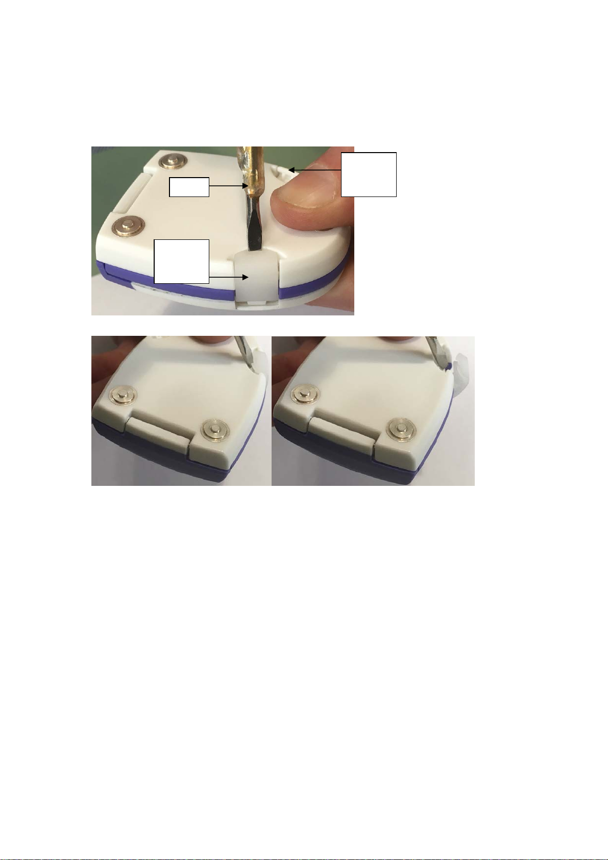
1. Open the Vpod device using the release clips (labelled ‘B’ in Figure 14 below).
Note:
The Left Release Clip can be opened by using the fingers only while the Right
Release Clip needs a tool to be unlocked (See Figure 3 and 4 below).
2. Place both coin cell batteries into the case, positive side upwards (i.e. the smooth
side with writing, ‘
3. Close the Vpod case by securing the release clips.
4. The Vpod will beep once* to indicate ‘Power On’.
Ensure older batteries are not used with new batteries in the device.
Only new batteries should be inserted into the device when replacing used batteries.
For information on battery disposal please refer to Section 10.0, Page 17.
* If the Vpod memory is full, two beeps will be heard approximately 30 seconds after the
‘Power On’ beep during Vpod start-up, otherwise only the ‘Power On’ beep will be heard.
If three beeps are repeatedly heard immediately after switching on, please see the
Section 14.0 Troubleshooting Guide.
+’ symbol will be etched on this side).
7
During monitoring, the Vpod should only be switched off during the following; when
batteries are being replaced, once monitoring has concluded or if the person intends not to
wear the Vpod for several hours.
NOTE: Healthcare professionals and patient must be familiar with the correct
procedure for inserting and replacing Vpod batteries.
Left
Release
Tool
Clip
Right
Release
Clip
Figure 3: Using the tool to unlock the Right Release Clip.
Figure 4: The tip of the tool is used to unlock the Right Release Clip.
6.7.2 Device Start-up
After the configuration settings have been selected the devices are now ready to be set up. A
Vpod must be paired with a Vcell before the system is used to allow the patient’s ECG data to
be sent to the Vpatch website.
Before commencing a new monitoring period or using the devices on a new patient, it is
important to pair the Vpod and Vcell, even if the devices have been paired previously.
Pairing clears any stored events from the device memory and restores the Vpatch
System’s to the default settings, i.e. the system records up to 20 seconds pre-event
and 30 seconds post-event ECG data when the Event Button is pressed or when one of
nine arrhythmias are detected (See Section 2.0 for a list of arrhythmias).
Figure 14 indicates V Patch device labelling.
8

/
ging
g
A
F
B
C
Figure 14: Device Labelling
A Event Button
D
Pairing Button
E
B Release Clips
C Char
Port
D On/Off Button
E LED
F Pairin
Button
9

The healthcare professional responsible for issuing, assigning or fitting a V Patch System must read and
r
A
understand the contents in Table 1 “System Setup”, be familiar with the device operation and expert in the
listed contents of section 14.0 “Troubleshooting Guide” PRIOR to using the device.
Function Indication
To configure the device, please refer to Section 6.4.2, before use. The length of the monitoring period is
chosen during the previous system configuration.
Switch on the Vcell by pressing ‘D’: ‘E’ will turn orange and then green while 1 beep is heard.
To pair the devices, press and hold ‘F’ on the Vcell until the pairing mode indication is seen:
1 beep and ‘E’ is green when ‘F’ is pressed initially
Enter Pairing Mode on the Vcell by
pressing and holding ‘F’:
‘E’ flashes green to indicate that it is in pairing mode and is searching for
Vpod.
‘E’ can now be released.
Once ‘E’ begins to flash green, the user has 60 seconds to complete the pairing process by switching on
the Vpod and placing it in pairing mode.
If pairing is not completed within 60 seconds the devices will timeout and return to normal operation.
If pairing is still required, the healthcare professional must switch the devices off and then on again and
repeat the sequence.
Insert the coin cell batteries into the
Vpod and close the case using ‘B’:
1 beep or 3 beeps (See Section 6.7.1, Page 7)
1 beep (depending on previous configuration) when ‘A’ is pressed initially
Press and hold ‘A’ on Vpod:
Repeated fast beeping while searching for Vcell
Long beep when successfully paired with Vcell
‘E’ on Vcell is stops flashing when successfully paired with Vpod
1 long beep is heard from the Vpod and ‘E’ stops flashing on the Vcell to indicate that it has successfully
paired and that the system has been reset to the default settings (30 seconds of ECG data recorded when
an arrhythmia is detected or when Event Button is pressed).
The Vcell will connect to the network to retrieve configuration settings.
Please note the solid orange LED described below to confirm that the device has connected successfully.
While the device is searching for a
Network connection
When a successful connection has
been established
If the Vcell is unable to connect to the
network
‘E’ is flashing orange
‘E’ is solid orange
‘E’ will stop flashing orange
The Vcell will then ensure it is in range with the Vpod (whether there is a successful connection to the
network or not).
The Vcell will then send any new configuration settings available to the Vpod. The LED sequence may vary
at this stage; however the system has successfully received the new settings when 3 beeps are heard from
the Vpod.
Sending configuration settings
‘E’ will be orange for a short time while data is transferred
3 beeps will be heard from the Vpod
Devices in range ‘E’ will remain solid green
‘E’ will become solid green again when the system is ready for use.
This indicates that the paired Vpod and Vcell are within range of each other.
The Vpod can now be connected to the Biosenso
rray that is applied to the patient.
When the devices are out of range, ‘E’ will not be lit, but will flash green approximately every 10 seconds
as it searches for the Vpod it was prev iously paired with.
To switch off the Vcell, press and hold ‘D’.
Vcell switching off ‘E’ is solid orange while 1 beep is heard
Table 1: System Setup
10

6.8 To Begin Monitoring
Once the devices have been set up and connected to the patient via the Biosensor Array,
the Event Button ‘A’ should be pressed to send an initial ECG trace to the server. This will
allow a predefined amount of data to be recorded and sent to the Vcell. One beep will be
heard from the Vpod when the event button is pressed.
The ECG file will be present on the website within a few minutes providing there is a
constant and uninterrupted cellular network signal. It is highly recommended that the ECG
file is viewed before the patient leaves the healthcare professionals workplace. This
verifies that the system is configured correctly.
6.9 Frequently Used Functions During the Monitoring Period
NOTE: If the Vpod becomes disconnected from the Biosensor Array during the
monitoring period, it should be reconnected as soon as possible.
NOTE: There are no frequently used functions available to the patient during the
monitoring period that they cannot safely use.
6.8.1 Pressing the Event Button
If the patient feels unwell during monitoring they must press the Event Button, ‘A’. One beep
will be heard from the Vpod. The Vpod will queue up to ten events if it is already recording
data. Two beeps will be heard from the Vpod every 5 minutes or when ‘A’ is pressed on the
th
5
occasion, and thereafter.
If events are queued on the Vpod, ensure that the Vcell is in range and in line of sight. If
events remain queued, please refer to Section 14.0 “Troubleshooting Guide”.
This recorded data is sent to the central receiving station for analysis by the patient’s clinician.
6.9.2 Out of Range Indicators
During use, the LED on the Vcell will be green to indicate that the Vpod and Vcell are within
range of each other. Should the Vpod and Vcell be out of range, the green LED will flash
approximately every 10 seconds until the devices are back in range again.
6.9.3 Low Battery Alarms
Low battery alarms may sound during the monitoring period:
Vpod: Single beep sounding every 5 seconds. The patient should replace the batteries if
the battery alarm sounds. (See Section 6.5.1). This alarm may be silenced by
pressing and holding ‘A’ until a long beep is heard. The low battery alarm can only be
silenced 5 times before the batteries must be changed.
Vcell: Single beep sounding every 5 seconds. This alarm can be silenced by pressing and
holding ‘F’ or connecting the device to the charger provided. The Vcell should be
connected to the charger as soon as possible.
If the battery level of the Vpod is no longer sufficient to record and transmit events, a critical
low battery alarm will sound. Batteries MUST be replaced at this point. The critical low
battery alarm on the Vpod is described below:
Vpod: Single beep sounding every 2 seconds. The wireless link between Vpod and Vcell
is now shut down and the Vcell will appear to be out of range (‘E’ will flash green
once every 10 seconds). The patient should replace the batteries as soon as possible.
(See Section 6.5.1, Page 12).
11

The battery level of the Vcell can be checked by pressing ‘F’ once at any time during use.
One beep and a green LED will indicate that there is sufficient battery level power in the
Vcell.
One beep and an orange LED will indicate that the battery level is low and the Vcell
requires charging.
6.9.4 Restarting the Vpod and Vcell
Should the Vpod or Vcell be switched off (intentionally or unintentionally), the user is not
required to re-pair the devices as outlined in Table 1. The Vpod and Vcell retains the most
recent device pairing information. It is important that the user avoids switching devices off
unnecessarily during any monitoring period.
To restart the devices:
Vpod: Ensure fresh batteries are inserted and that the Vpod case is closed correctly (See
Section 6.5.1). The sounding of one beep indicates correct operation.
If two beeps are sounded within 30 seconds, the Vpod memory is full.
ECG data will send to the Vcell when both devices are in range again. If three beeps
are repeated after switching on, please see Section 14.0 “Troubleshooting Guide”
Vcell: If the Vcell has sufficient charge, it should be switched on again by pressing ‘D’.
Otherwise connect the device to the charger provided and press ‘D’ if required.
6.10 Viewing the Patient’s ECG Data
To view the patient’s ECG file:
1. Log on to the Vpatch website using a user name and password.)
2. Refer to Section 6.4.2 for more information on selecting the correct patient.
3. Click on the patient’s first or last name in order to see the Patient Dashboard.
4. From the files listed in the “Recent Measurements” the clinician can view any of the
most recent ECG measurements sent to the Vpatch website.
5. Clicking on the “Overview” link will bring the clinician to the full list of events sent to
the website, with each monitoring period in a separate section.
7.0 Transmission of Data
If any events are recorded in an area of limited cellular network signal, the system is equipped
to ensure that no data is lost if communications are restored before the devices are re-paired.
Up to 10 events may be stored on the Vcell device at any one time.
The cellular communications also support global roaming functionality, permitting the user to
move between countries without losing any of the benefits of the Vpatch System.
12

r
8.0 Specifications
Size and Weight:
Vpod: External dimensions: 59mm x 48mm x 18mm
Weight: 34grams
Vcell: External dimensions: 86mm x 61mm x 20mm
Weight: 78grams
IP Rating:
Vpod: IP22
Vcell: IP21
FCC ID:
Vpod: 2ARNZ-1001
3G Vcell: 2ARNZ-1002.
The Vpod requires 2 x CR3032 Lithium coin cell batteries. Care must be taken to insert the
batteries correctly, with the positive side facing upwards. (See Section 6.5.1)
NOTE: The batteries MUST be removed from the Vpod when not in use.
Power Sources:
Device
Vpod 3.0 Coin Cell: Non-Rechargeable
Vcell 3.7 Li-Ion: Rechargeable
Battery Voltage
(V)
Table 2
Battery Type
CR3032 Coin Cell Battery:
(Specifications)
Nominal Voltage (V) 3
Nominal Capacity (mAh) 500
Continuous Standard Load (mA) 0.2
Operating Temperature (C) -30 to +60
Table 3
Mascot Type 2240 Li-Ion Battery Charger
(Containing 1.3 mm x 3.8 mm power connector):
Input Voltage
(VAC)
90-264 4.2 1.3 -25 ~ +40
Output Voltage
(V)
Current (Max)
(A)
Operating Temperature
(°C)
LED Indicators on Mascot Type 2240 Li-Ion Battery
Red LED Green LED
Table 4
Charge
NOTE: Do not use any other mains adapter with the charger as it may result in damage
to the Vcell unit or affect system operation.
Vcell is not fully charged Vcell is fully charged
Table 5
Expected Service Life
The Li-Ion battery in the Vcell is rated last for at least 300 charging cycles. At maximum use,
assuming a charging cycle of every 5 days, this should provide an expected service life of the
Vpatch System of 5 years.
13

√
Guidance and manufacturer’s declaration – electromagnetic immunity
The Wireless ECG Monitor is intended for use in the electromagnetic environment specified below. The
customer or the user of the Wireless ECG Monitor should assure that it is used in such an environment
Immunity test
Electrostatic discharge
(ESD)
IEC 61000-4-2
Guidance and manufacturer’s declaration – electromagnetic immunity – for equipment and systems that are
IEC 60601
Test level
±6 kV contact
±8 kV air
not life-supporting
Compliance
level
±6 kV contact
±8 kV air
Electromagnetic
environment - guidance
Floors should be wood,
concrete or ceramic tile. If floors
are covered with synthetic
material, the relative humidity
should be at least 30%.
Guidance and manufacturer’s declaration – electromagnetic immunity
The Wireless ECG Monitor is intended for use in the electromagnetic environment specified below. The customer or the
user of the Wireless ECG Monitor should assure that it is used in such an environment
Radiated RF
IEC 61000-4-3
80 MHz to 2.5 GHz
3 V/m
[E
]V/m
1
d = [1.17]√P…80MHz to 800 MHz
d = [2.33]
Where P is the maximum output power rating
of the transmitter in Watts (W) according to the
transmitter manufacturer and d is the
recommended separation distance in metres
(m)
Field strengths from fixed RF transmitters, as
determined by an electromagnetic site survey,
a
should be less than the compliance level in
each frequency range. b
Interference may occur in the vicinity of
equipment marked with the following symbol
P…800 MHz to 2.5GHz
Note 1: At 80 MHz and 800 MHz, the higher frequency range applies
Note 2: These guidelines may not apply in all situations. Electromagnetic propagation is affected by absorption and
reflection from structures, objects and people.
Field strengths from fixed transmitters, such as base stations for radio (cellular/cordless)
telephones and land mobile radios, amateur radio, AM and FM radio broadcast and TV
broadcast cannot be predicted theoretically with accuracy. To assess the electromagnetic
a
b
Guidance and manufacturer’s declaration – electromagnetic immunity – for equipment and systems that are
environment due to fixed RF transmitters, an electromagnetic site survey should be
considered. If the measured field strength in the location in which the Wireless ECG Monitor is
used exceeds the applicable RF compliance level above, the Vpatch System should be
observed to verify normal operation. If abnormal performance is observed, additional measures
may be necessary, such as re-orientating or relocating the Wireless ECG Monitor.
Over the frequency range 150 kHz to 80 MHz, field strengths should be less than
not life-supporting
14
[V1]V/m

r
Recommended separation distances between portable and mobile RF communication
equipment and the Wireless ECG Monito
The Wireless ECG Monitor is intended for use in an electromagnetic environment in which radiated RF
disturbances are controlled. The customer or the user of the Wireless ECG Monitor can help prevent
electromagnetic interference by maintaining a minimum distance between portable and mobile RF
communications equipment (transmitters) and the Wireless ECG Monitor as recommended below, according to
the maximum output power of the communications equipment.
Rated maximum
output power of
transmitter
W
0.01 0.12 0.23
0.1 0.37 0.75
1 1.17 2.33
10 3.70 7.36
100 11.70 23.30
For transmitters rated at a maximum output power not listed above, the recommended separation distance d in
metres (m) can be estimated using the equation applicable to the frequency of the transmitter, where P is the
maximum output power rating of the transmitter in watts (w) according to the transmitter manufacturer.
NOTE 1 At 80 MHz and 800 MHz, the separation distance for the higher frequency range applies.
NOTE 2 These guidelines may not apply in all situations. Electromagnetic propagation is affected by absorption
and reflection from structures, objects and people.
Recommended separation distances between portable and mobile RF communications equipment and the
equipment and system – for equipment and systems that are not life supporting
Separation distance according to frequency of transmitter
m
80 MHz to 800 MHz
d = [1.17]√P
800 MHz to 2.5GHz
d = [2.33]√P
8.1 EMC Compliance
This product is compliant with the electromagnetic compatibility requirements of IEC60601-1-
2.
Guidance and Manufacturer's Declaration – Electromagnetic Emissions
The Vpatch System is intended for use in the electromagnetic environment specified below.
The customer or the user of the Vpatch System should assure that it is used in such an
environment.
Emissions test Compliance Electromagnetic environment – guidance
RF emissions CISPR 11 GROUP 1 The Vpatch System uses RF energy only for its
internal function. Therefore, its RF emissions are
very low and are not likely to cause any
interference in nearby electronic equipment.
RF emissions CISPR 11 Class B The Vpatch System is suitable for use in all
establishments other than domestic and those
Harmonic emissions
IEC 61000-3-2
Voltage fluctuations/
flicker emissions
IEC 61000-3-3
15
Class A
Complies
directly connected to the public low-voltage
power supply network that supplies buildings
used for domestic purposes.

8.2 FCC Compliance
The Vpod device and Vcell device comply with part 15 of the FCC Rules. Operation is subject
to the following two conditions:
(1) This device may not cause harmful interference, and
(2) This device must accept any interference received, including interference that may cause
undesired operation.
NOTE:
This equipment (Vpod device and Vcell device) has been tested and found to comply with the
limits for a Class B digital device, pursuant to part 15 of the FCC Rules. These limits are
designed to provide reasonable protection against harmful interference in a residential
installation. This equipment generates, uses and can radiate radio frequency energy and, if
not installed and used in accordance with the instructions, may cause harmful interference to
radio communications. However, there is no guarantee that interference will not occur in a
particular installation. If this equipment does cause harmful interference to radio or television
reception, which can be determined by turning the equipment off and on, the user is
encouraged to try to correct the interference by one or more of the following measures:
Reorient or relocate the receiving antenna.
Increase the separation between the equipment and receiver.
Connect the equipment into an outlet on a circuit different from that to which the
receiver is connected.
Consult the dealer or an experienced radio/TV technician for help.
Caution:
Changes or modifications (not expressly approved by the party responsible for compliance)
could void the user's authority to operate the equipment.
16

emperature
tatio
9.0 Storage and Transport Conditions
The Vpatch System electronics must be stored between the temperatures of -20 °C and 40 °C
(-4 °F and 104 °F) and at 30% relative humidity. The electronics must be protected from water
and other liquids at all times.
T
Limi
n
Handle with care
Temperature Relative Humidity Air Pressure
Transport -10 to +60°C 10 to 90%** 700 to 1013 hPa
Storage -20 to +40°C 10 to 85%** 700 to 1013 hPa
Operation 0 to +40°C 20 to 80%** 800 to 1013 hPa
**Wet bulb limit of 7°C
9.1 Maintenance
Vpatch System Should be kept clean and periodically checked to ensure the integrity of the
case, hinges, contact points and battery contact points. Power leads and battery charger
should also be visually inspected for signs of wear and damage.
The system is to be cleaned before and after use on each patient. The device may be
cleaned using an alcoholic or non-alcoholic wipe and dried with a lint-free cloth. It is
recommended that that the device is kept in the supplied case while not in use and the
rechargeable battery charged periodically.
The following guidelines should be adhered to.
Care should be taken to ensure that the Vpod and Vcell devices do not come into
contact with water or any other liquids.
There are no user serviceable parts.
17
10.0 Disposal
The information below is sourced from a recommended battery manufacturer’s guideline
material:
The Vpod and Vcell are electronic devices and must be returned to the distributor for disposal.
Do not heat or dispose of any part of the Vpatch System in fire. The devices may burst or
release toxic materials.
Do not disassemble, apply excessive pressure or deform any part of the Vpatch System.
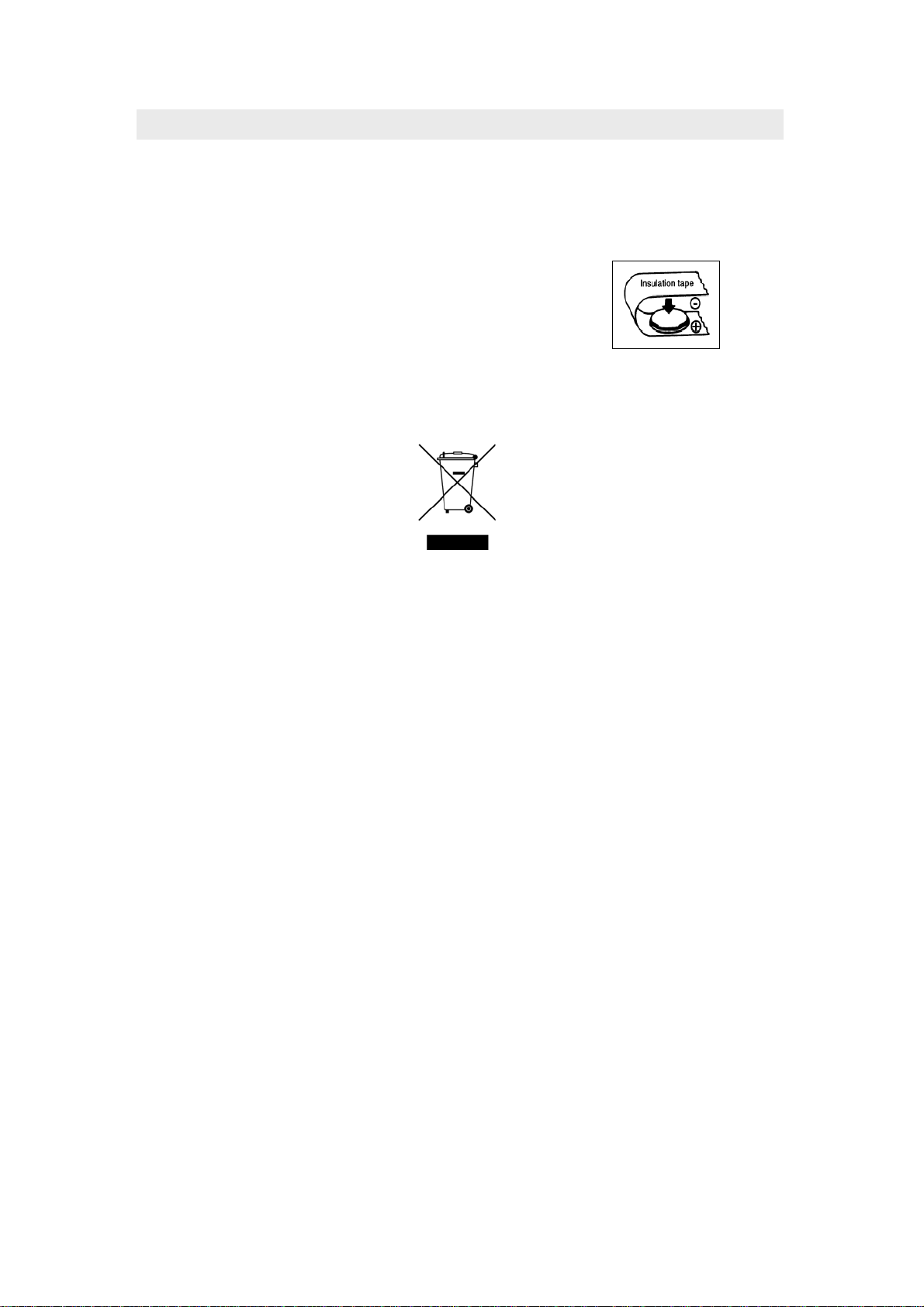
When disposing batteries, insulate the (+) and
(-) terminals of batteries with insulating tape,
etc. (see Figure 15). When disposed of
improperly, lithium batteries may short,
causing them to become hot, burst or ignite.
Figure 15
NOTE: Electronics and battery disposal must be in accordance with local and state
regulations
18
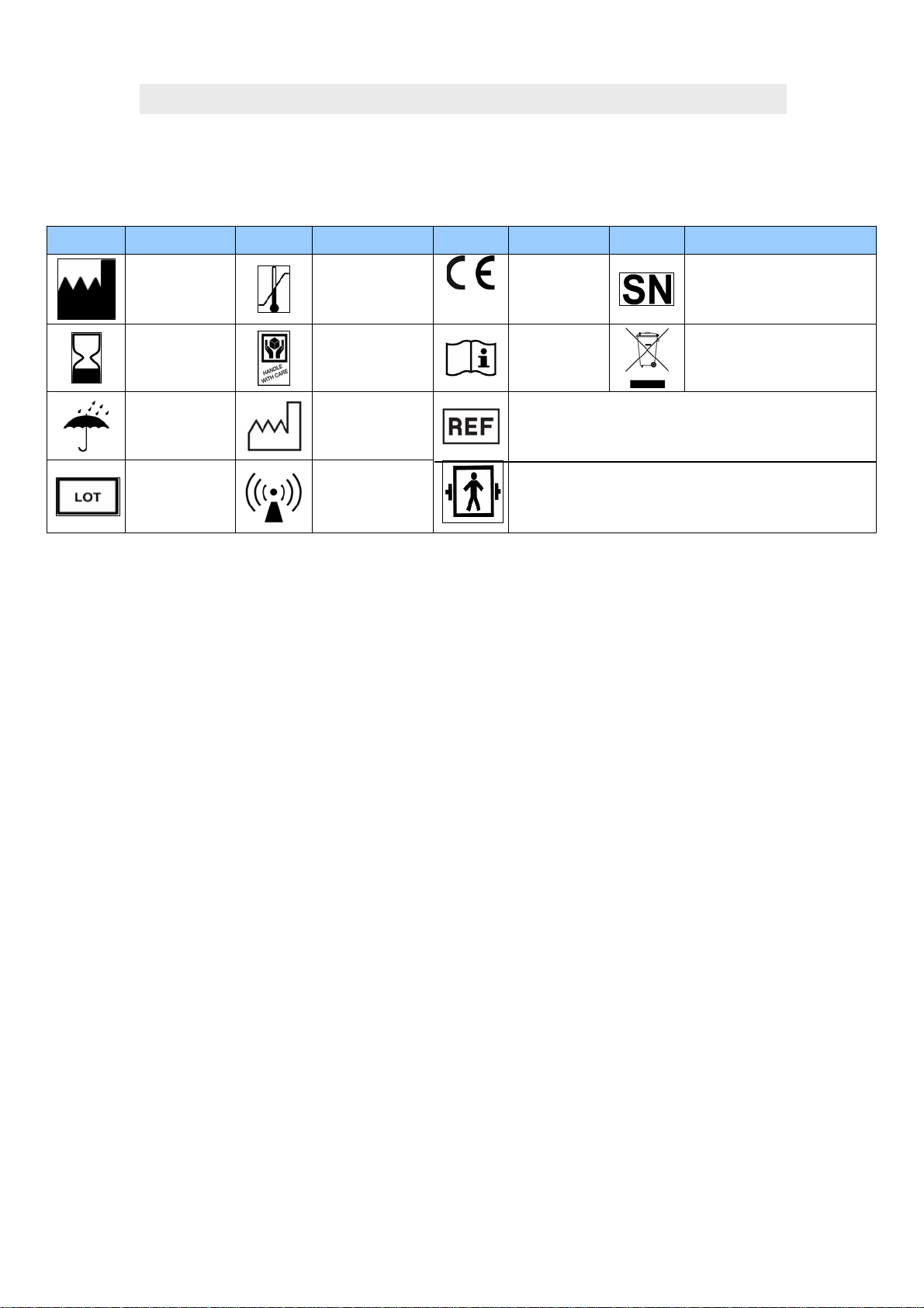
11.0 Explanation of Symbols Used on Vpatch System Documentation
The symbols used in the documentation for the Vpatch System are summarised in the
following
table:
Symbol Description Symbol Description Symbol Description Symbol Description
Manufacturer
Temperature
limitation
0805
CE Mark
Serial Number
Use-by date
Do not get wet
Batch code
Handle with care
Date of
manufacture
Non-ionizing
electromagnetic
radio
Consult
Instructions
for Use
Catalogue Number
Defibrillator Proof Type BF: The Vpod device is a type
BF device and has a high level of protection against
defibrillation energy as per EN 60601-1.
Equipment should not be
disposed of with normal
waste stream
Table 6
11.1 Vpatch System Model/Serial Numbers
The Vpatch System model/serial numbers are in the format shown below.
Vkit model number FG06120 contains:
1 x Vpod
1 x Vcell
1 x Mascot battery charger type 2240
1 x Carry case
The first three digits of the model/serial number are the model number and indicate the device
type (Vpod or Vcell). The last six digits are the serial number.
Vpod devices will have the model/serial numbers:
101-XXXXXX
001XXXXX
Vcell devices will have the model/serial numbers:
201-XXXXXX Representing models with 2G SIM cards
301-XXXXXX Representing models with 3G SIM cards
The device labels include a Global Trade Item Number (GTIN) that provides an additional
form of model identification.
19

V
V
V
V
V
V
V
V
12.0 Start-Up Guide
The following indicators and actions are required to start and configure the Vpatch System.
Press ‘D’ to switch on Vcell and wait for green LED and 1 beep.
START UP VCELL LED VCELL BUZZER VPOD BUZZER
Setup
Setup complete
1 flash
1 sec
Single
beep
If PAIRING is not required, switch on the Vpod immediately and skip to NETWORK.
To PAIR devices, press and hold ‘F’ on the Vcell until ‘E’ begins to flash.
Then switch on the Vpod and press and hold ‘A’ until 1 long beep is heard.
This indicates successful pairing.
PAIRING VCELL LED
While searching
Successful pairing
Default Settings reset
Vcell moves on to next
stage (see next table)
Fast
flashing
Successful
pairing
CELL BUZZER
POD BUZZER
The Vcell will then immediately connect to the Network. This LED sequence may var y slightly.
NETWORK VCELL LED
While searching
Successful
connection
For duration
Slow
flashing
of action
CELL BUZZER
POD BUZZER
The Vcell will then check that it is in range with the Vpod.
Fast
beeping
Long
beep
Single
beep
RANGE VCELL LED
In Range
CELL BUZZER
POD BUZZER
The Vcell will check for configuration settings and transfer them to the Vpod.
CONFIGURATION VCELL LED
Sending configuration
data
CELL BUZZER
POD BUZZER
Three
beeps
The green LED on the Vcell will light up, indicating that the devices are in range.
The system is now ready for use.
20
V
V
r
V
V
r
V
V
V
V
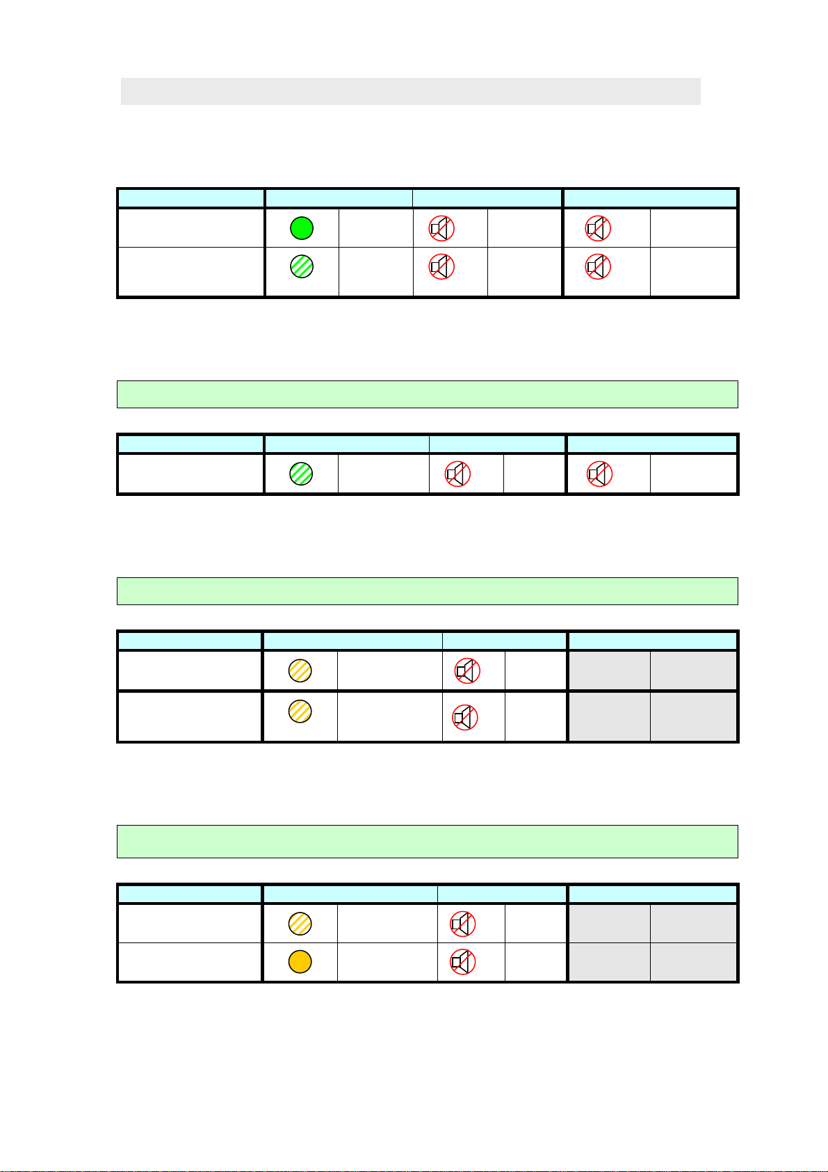
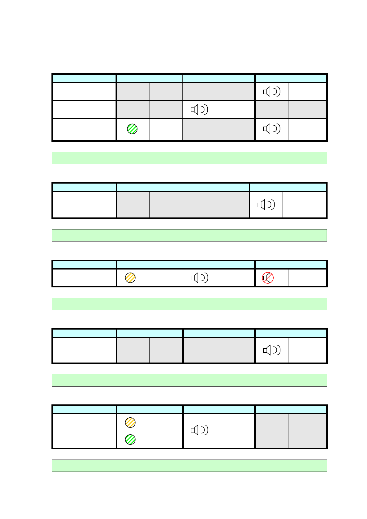
13.0 Indicator Guide
The following indicators can occur at any time during normal use.
Vpod/Vcell Range
RANGE VCELL LED
In Range
Out of Range
1 flash
every 10
seconds
ECG Data Transfer (from Vpod to Vcell)
If Vpod is in range of Vcell
ECG Data Transfe
Vpod to Vcell ECG
Transfer
ECG Data Transfer (from Vcell to Internet)
VCELL LED
Flashing for
duration
If ECG Data is on Vcell
CELL BUZZER
CELL BUZZER
POD BUZZER
POD BUZZER
ECG Data Transfe
While searching
Successful
connection and data
transfer
Vcell Network Checks
Every 4 hours the Vcell will connect to the Internet to check for new configuration settings.
The clinician/patient is not required to take any action.
VCELL LED
Slow flashing N/A N/A
Fast flashing
for duration of
transfer
CELL BUZZER
POD BUZZER
N/A N/A
NETWORK VCELL LED
While searching
Successful
connection
Slow flashing N/A N/A
For duration
of action
CELL BUZZER
POD BUZZER
N/A N/A
21
Warning Indicators
V
V
V
V
V
V
V
V
V
V
The following indicators can occur at any time during normal use. These indicators require a
corrective action to rectify the issue.
Low Battery
LOW BATTERY VCELL LED
Vpod Low Battery
Vcell Low Battery
Vpod Critically Low
N/A N/A N/A N/A
N/A N/A
Battery
Connect Vcell to charger or Replace Vpod batteries
Vpod Memory Full
MEMORY FULL VCELL LED
Ten events stored
on Vpod
N/A N/A N/A N/A
Ensure Vpod is in range of Vcell
Vcell Memory Full
Flash
every
10 sec
CELL BUZZER
N/A N/A
CELL BUZZER
Beep every
5 sec
POD BUZZER
Beep every
5 sec
N/A N/A
Beep every
2 sec
POD BUZZER
Double beep
every 5 min or
when Event
Button pressed
MEMORY FULL VCELL LED
Ten events stored
on Vcell
Double flash
every 5 min
CELL BUZZER
Double beep
every 5 min
POD BUZZER
Move to an area of cellular network coverage.
Vpod System Error
SYSTEM ERROR VCELL LED
System error
N/A N/A N/A N/A
CELL BUZZER
POD BUZZER
Repeated
triple beep
on Start Up
Switch Vpod off and on again. If error persists contact you distributor.
Vcell System Error
SYSTEM ERROR VCELL LED
Alternating
green and
orange
LEDs
System error
CELL BUZZER
One beep
every sec
POD BUZZER
N/A N/A
For further information on warning indications, please see the Troubleshooting Guide (Table
7).
22
Switch Vcell off and on again. If error persists contact you distributor.

14.0 Troubleshooting Guide
Problem Possible Solution
One beep heard every 5
seconds from the Vpod
One beep heard every 2
seconds from the Vpod
One beep heard every 5
seconds from the Vcell
This is the low battery alarm. To silence the alarm, press and hold ‘A’ until a
long beep is heard. Insert new batteries into the Vpod as soon as possible.
This is the critical low battery alarm. The Vpod has shut down communications
with the Vcell, which will therefore show the “Out of Range” indication (See
Section 13, Page 21). Insert new batteries into the Vpod as soon as possible.
This is the low battery alarm. To silence the alarm, press and hold ‘F’ or
connect the device to the charger provided. The Vcell must be connected to the
charger as soon as possible.
Connect the Vcell to the charger provided. If the LED on the charger is red the
Vcell requires charging. If the LED on the charger is green you may need to
disconnect the charger from the mains while it is still connected to the Vcell,
Vcell will not switch on
reconnect and try again. The Vcell should be charged for 3hrs (minimum).
If the device does not switch on after charging, ‘D’ should be pressed and held
for approximately 15 seconds. Release ‘D’ and switch the Vcell on as normal.
The Vcell will then switch on. This results in a full reset of the Vcell.
Press and hold ‘D’ for approximately 15 seconds. Release ‘D’ and switch the
Vcell will not switch off
Vcell on as normal. The Vcell will then switch on. This is a full reset of the Vcell.
Any ECG data stored on the device can still be transmitted to the Vpatch
website.
Switch the Vpod off and on again. If there is still no beep heard on start up,
No beep heard from
Vpod when switched on
No pairing beeps heard
from Vpod /
No flashing green LED
from Vcell /
Devices will not pair
No beep heard from the
Vpod when Event
Button is pressed
place new batteries in the Vpod (See Section 6.5) and retry. If there is no
audible tone after new batteries have been inserted, please contact your
distributor.
Pairing beeps may be heard from the Vpod up to 10 seconds after initially
pressing and holding the pairing button. If no pairing beeps or LED indications
are heard or seen after this time, ensure that enough digital pressure is
consistently placed on the device buttons.
Switch both devices off and on again and re-try.
Insert new batteries into the Vpod and re-try.
Switch the Vpod off and on again. If there is still no beep heard when the Event
Button is pressed, place new batteries in the Vpod (See Section 6.5) and retry.
If there is no tone after new batteries have been inserted, please contact your
distributor.
Two beeps heard from
the Vpod every 5
minutes and when the
Event Button is pressed
Two beeps and two
orange LED flashes
from Vcell every 5
minutes
The Vpod has ten events stored in its memory and is now full. Ensure the Vpod
and Vcell are within range and are in direct line of sight of each other.
The Vcell has ten events stored in its memory and is now full. Ensure the user
is in an area of good cellular network. Press ‘F’ on the Vcell twice, ensuring a
beep is heard with each press to allow the Vcell to attempt a network
connection. Additionally, the Vcell will do this every 4 hours itself.
Table 7 (continued on following page)
23

Problem Possible Solution
Three beeps heard from
the Vpod when the
Event Button is pressed
Three beeps repeatedly
heard from the Vpod
when it is switched on
Alternating green and
orange LEDs and one
beep every second on
the Vcell
The Vpod has not been configured to record ECG data when ‘A’ is pressed.
See Section 6.4 for information on configuration.
This is a system error. The Vpod must be switched off and on. If the error
persists, please contact your distributor.
This is a system error. The Vcell must be switched off and on. If the error
persists, please contact your distributor.
Ensure that the recommended skin prep and removal of excessive body hair
were followed and attended to if not.
Ensure the magnetic studs on the Vpod and Biosensor Array are clean and
Poor quality ECG signal
from one or more leads
free of all debris.
Ensure the Vpod is securely connected to the Biosensor Array via each of the
magnetic studs.
Ensure the Biosensor Array has been applied correctly, as outlined in Section
6.3, Page 4.
Ensure the correct Vpod Serial Number is assigned to the correct patient and
that the monitoring period has not ended (See Section 6.4).
Events cannot be
viewed on Vpatch
System website
If the Vpatch System is an area of limited or zero cellular network coverage,
ECG data sent from the Vpod to the Vcell cannot be transmitted to the Vpatch
website. The Vcell can store up to ten events in its memory. Once the system
returns to an area of cellular network coverage any stored events will be
transmitted to the Vpatch website.
The Vcell does not
connect to network
during set-up
If the Vpatch System is being set up in an area of limited or zero cellular
network coverage. Move to an area of cellular network coverage and re-try.
You can initiate the Vcell to attempt to connect to the network by pressing ‘F’
twice, ensuring that a beep is heard with each button press. If the Vcell
consistently fails to connect to the network, please contact your distributor.
Table 7 (Continued)
24

15.0 Standards
The Vpatch System has been designed and tested to conform to the essential requirements
and provisions of European Council Medical Devices Directive 93/42/EEC Annex II (excluding
Section 4) for a Class IIa device, (under Annex IX Rule 10 – non-invasive active device),
obtaining the European CE Mark.
The device has been designed to conform to the following International Standards:
IEC 60601-1 :
2005/AMD1:2012/COR1:2014
IEC 60601-1-2 :2014 EN 1041 : 2008 BS PD IEC TR 60878:2003
IEC 60601-1-6 : 2010+AMD1: 2013 ANSI/AAMI EC57:2012 EC38 : 1998
IEC 60601-1-11:2015 BS EN 60529: 1992
AAMI EC 12:2000 (R2015) ISO 15223-1:2016
ISO 14971:2012 BS EN 980:2008
EN 60950-1 : 2001 plus amendments
A11:2004
ISO 13485 2016
Table 8
16.0 Warranty
Medical Manufacturers products are warranted to be free from manufacturing and material
defects for a period of 1 year from the date of shipment by the manufacturer to the distributor
or directly to the health care professional workplace.
Excluded from this warranty are the CR3032 Lithium Coin Cell Batteries and the Mascot
Battery Charger.
Any repairs made to the product that are not covered by the warranty shall be billed to the
customer.
For service or technical support contact your distributor.
25

17.0 Distributor Details
Vpatch Cardio Pty Ltd.
1221 Toorak Road,
Camberwell, Victoria,
Australia
3124
w: www.vpatchcardio.com
e: info@vpatchcardio.com
18.0 Manufacturer Details
Manufactured by:
Medical Manufacturers
Unit 131, 45 Gilby Road,
Mt. Waverley, Victoria,
Australia
3149
0805
19.0 Authorized Representative in the European Community
Medical Manufacturers
Europe Co Ltd.
St. Marys House
Netherhampton, Salisbury
Wiltshire, SP2 8PU
United Kingdom
Tel: +44 7831 429 245
26
 Loading...