

vpai360 VPai Slide User Manual

V
U
Since
V
P
a
se
r
PaiApp and fi
r
i·
M
mware will be
1
Sli
d
an
u
upgradedconti
e
al
nuously, pleas
e
refer to the physical object.
2017-08-10

2
Contents
1.Appearance .......................... ... ..... ...... .. ...... ..... ... ..... ..... ... ..... ... ..... ...... .. ...... ..... ... ..... ............. 4
2.Begin to Use .......................................................................................................................... 5
2.1Charge the Battery .................................. .. ...... ..... ... ..... ..... ... ..... ...... .. ...... ..... ... ..... ..... ..... ... 5
2.2 Power-ON & Power-OFF ............................................................................................... 5
2.3 Use Mode ...... .. ................................... ................................... .......................................... 5
2.3.1Independent Operation ....................................... .................................. ................ 5
2.3.2App Operation....................................................................................................... 6
3.App Functions .................................................... .................................. ... ............................. 9
3.1VPai .................................................................................................................................. 9
3.1.1Camera Settings .................................... ... ................................... .......................... 9
3.1.2Take Photos .............................................................. ... .................................. ...... 12
3.1.3Video and Time-lapse .......................................................................................... 13
3.1.4Live ...................................................................................................................... 14
3.2Gallery ............................................................................................................................ 20
3.2.1Local Gallery ........................................................... ........................................... 21
3.2.2Camera Gallery ....................... ................................... .................................. ...... 23
3.2.3Cloud Gallery ....... ... ................................................................... ........................ 24
3.3Share ............................................................................................................................... 24
3.4Space ........................ ...................................................... ................................................ 26
3.5Me ............................ ........................... ........................... .......................... ...................... 29
4.360player ............................ ................................ ................................ ................................ 31

3
Warning
This device complies with part 15 of the FCC Rules. Operation is subject to the following two
conditions: (1) This device may not cause harmful interference, and (2) this device must accept
any interference received, including interference that may cause undesired operation.
Note: This equipment has been tested and found to comply with the limits for a Class B digital
device, pursuant to part 15 of the FCC Rules. These limits are designed to provide reasonable
protection against harmful interference in a residential installation. This equipment generates
uses and can radiate radio frequency energy and, if not installed and used in accordance with
the instructions, may cause harmful interference to radio communicat i ons . H owev er, there is no
guarantee that interference will not occur in a particular installation. If this equipment does cause
harmful interference to radio or television reception, which can be determined by turning the
equipment off and on, the user is encouraged to try to correct the interference by one or more of
the following measures:
-Reorient or relocate the receiving antenna.
-Increase the separation between the equipment and receiver.
-Connect the equipment into an outlet on a circuit different from that to which the receiver is
connected.
-Consult the dealer or an experienced radio/TV technician for help.
Any Changes or modifications not expressly approved by the party responsible for
compliance could void the user's authority to operate the equipment.
SAR Warning Body Operation
This device was tested for typical body support operations. To comply with RF exposure
requirements, a minimum separation distance of 0.0 cmmust be maintained between the user’ s
body and the device, including the antenna. Third-party belt-clips, holsters, and similar
accessories used by this device should not contain any metallic components. Body accessories
that do not meet these requirements may not comply with RF exposure requirements and should
be avoided. Use only the supplied or an approved antenna.
4
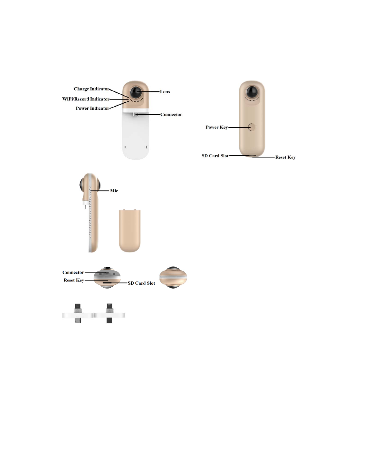
1. Appearance
Front View Back View
Left ViewPower Bank
Upward ViewTop Vi ew
Micro-B to Micro-B Connector Micro-B to Type-C Connector
Power Key:Click Power Key for short time is taking a photo; click Power Key between
0.4s and 1.8s start recording video or stop it, when recording video the blue light will flash
all the time except the end; click the Power Key more than 3.5s the camera will be turn off,
click the Power Key for 2s the camera will be turn on.
Reset Key: Click the reset key can reboot the camera.
Power Bank Indicator: Flashone time, 0-25% voltage; flash twice times,25-50% voltage;
flash three times, 50-75% voltage; flash four times,75-100% voltage; the indicator always

5
on is full voltage.
Micro SD Card Slot: The camera can support the max storage is 128GB Micro SD
card(for short SD card)
The SD card capacity over 32GB must change its format to NTFS file system.
USB connection record/take photos, files are saved in your phone.WI-FI connected with SD card
record/take photos, files are saved in SD card; WI-FI connected without SD cardrecord/take photos, files
are saved in your phone.
2. Begin to Use
2.1 Charge the Battery
Please use the supplied USB PowerAdapter to connect the camera. When charging the
camera, the charge lamp (red light) is always on, if it’s fully charged, the red light will turn
off; when the battery is low, the green light will flash.
The camera is limited to use a USB power adapter with output power rating of 5V/1.5A.
Charging with other adapters may damage the battery.
2.2 Power-ON & Power-OFF
Power-ON: Press the Power Key of camera and wait for 2 seconds, then release it. After a
period of time, the blue light is on and accompanied by a voice prompts, it means that t he
camera was really start-up. The whole process required about 15s.
Power-OFF: Press the Power Key of camera and wait for over 3.5 seconds, then release it,
the blue light is flashing at this moment. When all lights go out, the camera is turned off.
2.3 Use Mode
2.3.1 Independent Operation
Camera can also use without connec ting to the Mobile, click Power Key for short t i me is
taking a photo, the blue light will flash onc e; click Power Key between 0.4s and 1. 8 s start
recording a video or stop it, when recording video the blue light will flash all the time.

2.3.
2
App
Figu
r
W
corr
e
And
8.0a
n
And
Baid
u
from
down
O
T
and i
t
s
ucc
e
atten
t
s
ettin
US
B
U
S
In
dire
c
pops
App Ope
r
Downloa
d
e 1: Androi
d
hen you co
n
sponding
Q
roid App su
p
d above.
roid App ca
App assista
n
VPai official
load.
G: The USB
is necessar
y
ssfully,your
p
ion to some
o
gs]->[OTG
c
Connecti
o
B connectio
n
stall the Pa
i
tion of arr
o
up as Figu
r
ation
and Insta
l
App Dow
n
nected ca
m
Rcode of
t
port Androi
n also down
l
t, Tencent p
h
website(w
w
version cam
e
to open aut
o
hone will a
u
ther phones
onnection]
a
n
only suppo
r
r App on
m
w on the a
d
e 3:
l
load Figure
eras first
t
he system,
d 5.0and ab
o
oad it from
V
one assista
n
w.vpai360.
c
ra need to i
n
matic rotati
n
tomatically
o
such as OP
P
nd then star
t
t to Android
A
obile, and
c
apter mus
t
2: iOS App
D
ime,Please
download
t
ve, and the
p
Pai official
w
t, peas platf
oom
)or ent
e
sert into M
o
g screen fu
n
pen 720VP
a
O, need to e
n
using the O
T
pp.
onnect m
o
be inserte
d
6
ownload
use mobile
he VPai A
p
hone must s
u
ebsite(ww
w
rm and so o
n
r App Store
s
bile’s USB i
n
ction for yo
u
i APP and e
n
ter into [sy
s
G function,
c
bile to the
c
into the c
a
phones to
s
p.
pport OTG
;
.vpai360.c
o
;
iOS App
c
earch“VP
a
terface thro
u
r phone. You
r
ter preview
m
tem setting]
-
an only be
u
amera via
a
mera), the
n
can and
iOS App su
p
m),Google
an also do
w
i”directly a
gh the USB
c
phone con
n
odel. Pay
m
>[other
se the came
r
USB ada
p
wait until
V
port iOS
Play Store,
nload it
nd then
onnector,
ect camera
ore
a.
ter (the
Pai

7
Figure 3: Camera USB connection tips
Click “OK”, the system will automatically enter the VPai application, if you select “Use
by default for this USB camera”, there no longer have the tips when you connect the
camera,it will enter VPai application directly.
After the camera is connected, click the Photo button to take pictures.Images can be
viewed in the Gallery, and shared to the social platforms. Details refer to Gallery
and Share.
WI-FI Connection
Because of iOS App is similar to Android App functions and interfaces, the following will describe
an Android App as an example, iOS users for reference.
Through the mobile WI-FI connect the camera hotspot, open APP enter the camera and do
the work on the preview interface directly. Please install the APP in your phone in advance
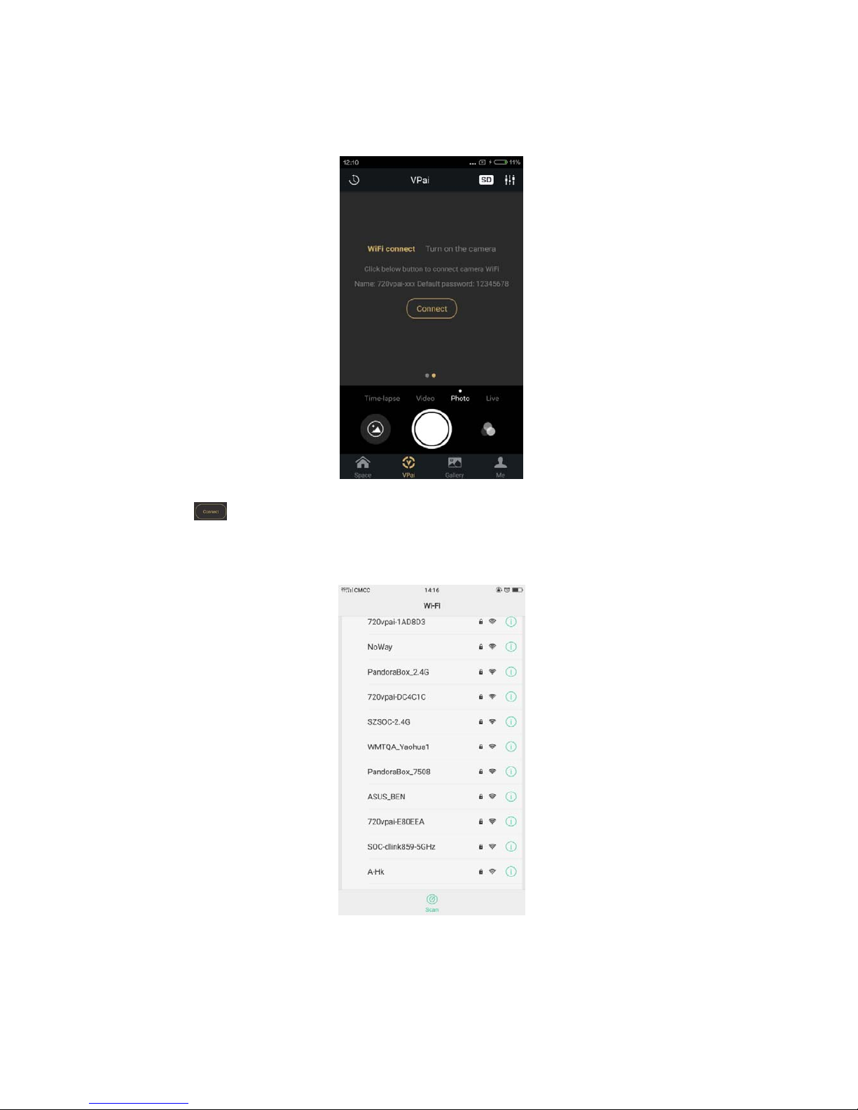
downloaded, open it and then enter the VPai connect interface as shown in Figure 4:
8
Figure 4: WI-FI Connection VPai preview interface
Click button, enter the interface as shown in Figure 5, so you can select the camera
hotspot, the default password is: 12345678,you can change the connect password in the
Camera Setting->Hotspot password interface.
Figure 5: VPai WI-FI selection interface
When the camera hotspotis connected, you can ente r the VPai preview interface , as shown
in Figure 6 below:
9
3. App Functions
VPaiApp contains the following features: 1. VPai: Including camera settings, photo shoo t ,
video recording, live management; 2.Gallery: View and edit pictures / videos; 3.Share: select
the image / video in the Gallery to share it with the social platforms; 4.Space: VPai360
built-in sharing platform; 5.Me: Acco unt ma nagement, FAQs, etc.
3.1 VPai
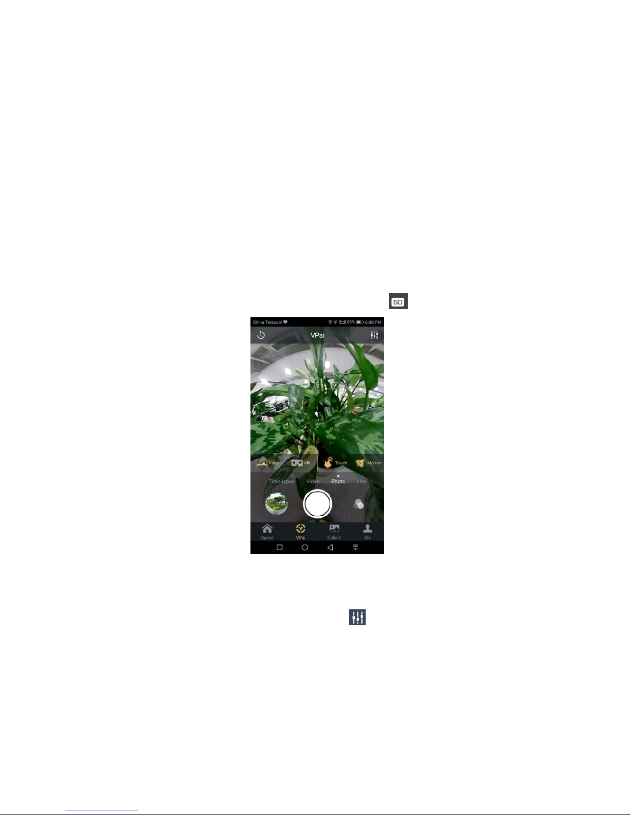
After connected, the
VPai preview interface as picture below. In the VPai interface, you
can switch the camera to: Time-lapse, Video, Photo, Live. Touch the button on the screen to
switch to the corresponding mode. If inserted the SD card, the top right corner close to the
Camera Settings button will have an SD card icon is displayed
.
Figure 6: VPai preview interface
3.1.1 Camera Settings
USB Connection
When USB connecting, click the Camera Settings that you will enter it, as shown in
Figure7:
10
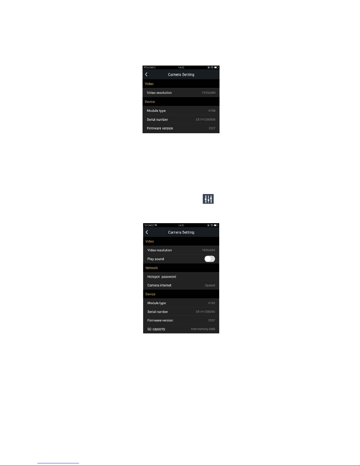
Figure 7: USB Connection Camera Settings interface
Video resolution: It can set the Camera’s resolution to 2048x1024 or 1920x960.
Device: You can view the Camera’s Module type, Serial number, Firmware version atthis
place.
WI-FI Connection
When WI-FI connecting, click the Camera Settings that you will enter it, as shown
in Figure8:
Figure 8: WI-FI Connection Camera Settings interface
Video resolution: It can set the Camera’s resolution to 2048x1024 or 1920x960.
Play sound: It can open/close the sound in the preview interface.
Network
:It can change hotspot password, connect to camera network.
Hotspot password:Click on the hotspot password entered the hot password change
interface, such as the need to change the password, please enter at least 8 characters, when
input characterscan switch show password or hide the password, click ok button to complete
 Loading...