


Series 5100/6100
™
Voice/Data Router
Reference Manual
MGCP Telephony

Trademarks and copyrights
All trademarks and registered trademarks listed belong to their respective owners.
Vpacket, Vpacket Communications, and the Vpacket 5100/6100 Series Voice/Data Router are registered trademarks of Vpacket
Communications, Inc., Milpitas, California.
Vpacket Communications, Inc. does not warrant that the hardware will work properly in all environments and applications, and makes no
warranty and representation, either implied or expressed, with respect to the quality, performance, merchantability, or fitness for a particular
purpose.
The products and programs described in this document are licensed products of Vpacket Communications, Inc. This document contains
proprietary information protected by copyright, and this document and all accompanying hardware, software, and documentation are
copyrighted. Vpacket Communications, Inc. has made every effort to ensure that this manual is accurate. However, information in this guide is
subject to change without notice and does not represent a commitment on the part of Vpacket Communications, Inc. Vpacket Communications,
Inc. makes no commitment to update or keep current the information in this document, and reserves the right to make changes to this manual
and/or product without notice. Vpacket Communications, Inc. assumes no responsibility for any inaccuracies and omissions that may be
contained in this document. If you find information in this document that is incorrect, misleading, or incomplete, we would appreciate your
comments and suggestions.
No part of this document may be reproduced or transmitted in any form or by any means, electronic or mechanical, including photocopying,
recording, or information storage and retrieval systems, for any purpose other than the purchaser's personal use, without the express written
permission of Vpacket Communications, Inc.
Copyright © 2000-2002 by Vpacket Communications, Inc.™ U.S. Patents Pending. All Rights Reserved. Reproduction or media conversion by
any means is protected by copyright and may only occur with prior written permission of Vpacket Communi
cations, Inc.
The PSQM technology included in this product is protected by copyright and by European, US, and other patents, and is provided under license
from OPTICOM Dipl. Ing. M. Keyhl GmbH, Erlangen, Germany, 2001
1390 McCarthy Boulevard
Milpitas, CA 95035
Tel: 1(866)VPACKET (872-2538)
Fax: 1(408)433-5870
E-mail: mail@vpacket.com
Web: http://www.vpacket.com
Document title Date
issued
Product number Release
Vpacket Series 5100/6100 Voice/Data Router Reference Manual MGCP
Configuration
June 2002 750-0031-001, Rev A 2.1.1
Vpacket 5100/6100 Series Voice/Data Router Reference Manual
(Data Features)
750-0025-001, Rev A
Vpacket 5100/6100 Series Voice/Data Router SIP Telephony Configuration 750-0032-001, Rev A
Vpacket 5100/6100 Series Voice/Data Router H.323 Telephony Configuration 750-0033-001, Rev A
Vpacket 5100/6100 Series Voice/Data Router Web Interface Manual 750-0035-001, Rev A

About this manual

About this manual
ii Vpacket 5100/6100 Series MGCP Telephony

Content summary
Vpacket 5100/6100 Series MGCP Telephony
iii
Audience
This manual is written for the technical staff of a service provider, who are responsible for the
telephony configuration of a Vpacket 5100/6100 Voice/Data Router (VDR). These users include,
but are not limited to, network technicians, systems administrators, and network operation staff.
Content summary
This manual contains all of the information you need to configure a 5100/6100 VDR to operate
within an MGCP environment. Table 1 lists the chapters and appendixes and a summary of each.
Table 1. Chapter summaries
Location Contents
Chapter 1 About MGCP Describes MGCP
Chapter 2 Coding profile
commands
Explains the coding profile commands and gives CLI examples
Chapter 3 TCID commands Explains the TCID commands and gives CLI examples
Chapter 4 MGCP commands Explains the MGCP-related commands and gives CLI examples
Chapter 5 T1 interface
commands
Explains the T1 interface commands
Chapter 6 Voice quality
commands
Explains the voice quality commands
Chapter 7 Default coding
profiles and TCID settings
Lists the default codecs

About this manual
iv Vpacket 5100/6100 Series MGCP Telephony
Conventions
This manual uses typeface, syntax, and messages to alert you to information of special interest.
Typefaces
Table 2 lists the typefaces that are used in this manual.
Command syntax
The syntax of commands is described using the following conventions:
• Angle brackets (<fill_in_the_blank >) denote required parameters or arguments.
• Square brackets ([ ]) denote optional elements.
• A pipe (|) separates choices.
Messages
Notes, cautions, and warnings are posted throughout the manuals to give supplementary
information and encourage safety awareness and safe practices.
Notes
Notes are supplemental information requiring your attention.
For example:
Note. Please remember to go to the Vpacket Web site and complete the online
Warranty Registration Card. Doing so registers your Vpacket 5100/6100 VDR and
allows you to receive the latest information, technical support, and upgrades
applicable to your unit.
Table 2. Typefaces and their meanings
Typefac e Description
Bold Designates menus, commands, and parameters
Courier Designates output resulting from a command issued by a user and messages
issued via a telnet or terminal-emulation screen

Related documentation
Vpacket 5100/6100 Series MGCP Telephony
v
Cautions
Cautions are information requiring extra attention.
For example:
Caution. No system-level confirmation message appears during the deletion.
Warnings
Warnings are information that, if not followed, could result in injury or equipment damage.
For example:
Warning. Use of longer screws could result in damage to internal components.
Related documentation
The documentation set related to the Vpacket 5100/6100 VDR includes all documents on the
CD-ROM that was shipped with the unit:
• Vpacket 5100/6100 Series Voice/Data Router Installer’s Guide, Release 2.1
•Quick Start Guides
• T1 and dual T1 Quick Start Guide
• SDSL Quick Start Guide
• Ethernet WAN Quick Start Guide
• T1-PRI Voice Quick Start Guide
•Vpacket 5100/6100 Series Voice/Data Router Datasheet
The reference manual is broken down into five sections allowing you to print only the sections
that apply to your network environment:
• Vpacket 5100/6100 Series Voice/Data Router Reference Manual (Data Features)
• Vpacket 5100/6100 Series Voice/Data Router MGCP Telephony Configuration
• Vpacket 5100/6100 Series Voice/Data Router SIP Telephony Configuration
• Vpacket 5100/6100 Series Voice/Data Router H.323 Telephony Configuration
!
WARNING

About this manual
vi Vpacket 5100/6100 Series MGCP Telephony
Contact information
For more information about the Vpacket 5100/6100 Series VDRs, please contact us using any of
the following methods.
Voice calls
We welcome your calls at 1(866) 872-2538 (VPACKET) Monday through Friday, from 9:00 am to
6:00 pm Pacific Time. Voice mail is available during non-business hours.
E-mail
If you prefer, you can send information requests to our e-mail address: info@vpacket.com
Fax number
You can also send your requests for information to our 24-hour fax number:
1(408) 433-5870
Website
Our website contains valuable information about our products. We encourage you to visit us at
http://www.vpacket.com

Contents
Vpacket 5100/6100 Series MGCP Telephony vii
About MGCP 1
MGCP and voice services over IP . . . . . . . . . . . . . . . . . . . . . . . . . . . . . . 3
Setting up voice ports for MGCP . . . . . . . . . . . . . . . . . . . . . . . . . . . . . . . 5
Coding profiles. . . . . . . . . . . . . . . . . . . . . . . . . . . . . . . . . . . . . . . . . . . . . . . . . . . . 5
TCID . . . . . . . . . . . . . . . . . . . . . . . . . . . . . . . . . . . . . . . . . . . . . . . . . . . . . . . . . . . 5
Activating and storing configurations . . . . . . . . . . . . . . . . . . . . . . . . . . . . 6
Evaluating call quality . . . . . . . . . . . . . . . . . . . . . . . . . . . . . . . . . . . . . . . . 6
Accessing MGCP commands . . . . . . . . . . . . . . . . . . . . . . . . . . . . . . . . . . 7
Accessing the help feature . . . . . . . . . . . . . . . . . . . . . . . . . . . . . . . . . . . . 7
Viewing the DSP version . . . . . . . . . . . . . . . . . . . . . . . . . . . . . . . . . . . . . 8
Recommended FAX settings . . . . . . . . . . . . . . . . . . . . . . . . . . . . . . . . . 12
Coding profile commands . . . . . . . . . . . . . . . . . . . . . . . . . . . . . . . . . . . . 12
Assigning codecs to coding profiles . . . . . . . . . . . . . . . . . . . . . . . . . . . . . . . . . . 13
Setting the coding usage. . . . . . . . . . . . . . . . . . . . . . . . . . . . . . . . . . . . . . . . . . . 14
Viewing coding profiles . . . . . . . . . . . . . . . . . . . . . . . . . . . . . . . . . . . . . . . . . . . . 15
Setting the voice information field . . . . . . . . . . . . . . . . . . . . . . . . . . . . . . . . . . . . 17
Setting the nominal delay (jitter) . . . . . . . . . . . . . . . . . . . . . . . . . . . . . . . . . . . . . 19
Setting the maximum delay (jitter). . . . . . . . . . . . . . . . . . . . . . . . . . . . . . . . . . . . 19
Setting the adaptive playout function. . . . . . . . . . . . . . . . . . . . . . . . . . . . . . . . . . 20
Setting the DTMF relay mode . . . . . . . . . . . . . . . . . . . . . . . . . . . . . . . . . . . . . . . 21
Setting the VAD mode. . . . . . . . . . . . . . . . . . . . . . . . . . . . . . . . . . . . . . . . . . . . . 21
Setting an audio threshold. . . . . . . . . . . . . . . . . . . . . . . . . . . . . . . . . . . . . . . . . . 22
Setting the silence detect time. . . . . . . . . . . . . . . . . . . . . . . . . . . . . . . . . . . . . . . 22
Setting a silence detection level . . . . . . . . . . . . . . . . . . . . . . . . . . . . . . . . . . . . . 23
Setting tone detection . . . . . . . . . . . . . . . . . . . . . . . . . . . . . . . . . . . . . . . . . . . . . 23
Enabling or disabling the echo canceller. . . . . . . . . . . . . . . . . . . . . . . . . . . . . . . 24
Setting the processor mode for the echo canceller. . . . . . . . . . . . . . . . . . . . . . . 24
Setting the echo canceller tail length. . . . . . . . . . . . . . . . . . . . . . . . . . . . . . . . . . 25
Setting the echo canceller processor value. . . . . . . . . . . . . . . . . . . . . . . . . . . . . 25
Setting the refresh state . . . . . . . . . . . . . . . . . . . . . . . . . . . . . . . . . . . . . . . . . . . 26
Setting the echo canceller refresh coefficient . . . . . . . . . . . . . . . . . . . . . . . . . . . 26

viii Vpacket 5100/6100 Series MGCP Telephony
CONTENTS
TCID commands 27
TCID commands . . . . . . . . . . . . . . . . . . . . . . . . . . . . . . . . . . . . . . . . . . . 29
Required TCID commands . . . . . . . . . . . . . . . . . . . . . . . . . . . . . . . . . . . 31
Assigning a TCID number and coding profile . . . . . . . . . . . . . . . . . . . . . . . . . . . . 31
Setting the notify entry . . . . . . . . . . . . . . . . . . . . . . . . . . . . . . . . . . . . . . . . . . . . . 32
Setting the TCID endpoint . . . . . . . . . . . . . . . . . . . . . . . . . . . . . . . . . . . . . . . . . . 32
TCID FXS loopstart . . . . . . . . . . . . . . . . . . . . . . . . . . . . . . . . . . . . . . . . . 33
Setting the on hook level . . . . . . . . . . . . . . . . . . . . . . . . . . . . . . . . . . . . . . . . . . . 33
Setting the seize detect parameter. . . . . . . . . . . . . . . . . . . . . . . . . . . . . . . . . . . . 34
Setting the originator clear detect parameter . . . . . . . . . . . . . . . . . . . . . . . . . . . . 34
Setting the answer-side clear detect . . . . . . . . . . . . . . . . . . . . . . . . . . . . . . . . . . 35
Miscellaneous TCID parameters . . . . . . . . . . . . . . . . . . . . . . . . . . . . . . 35
Setting the TCID mode. . . . . . . . . . . . . . . . . . . . . . . . . . . . . . . . . . . . . . . . . . . . . 35
Setting the receive gain . . . . . . . . . . . . . . . . . . . . . . . . . . . . . . . . . . . . . . . . . . . . 36
Setting the transmit gain. . . . . . . . . . . . . . . . . . . . . . . . . . . . . . . . . . . . . . . . . . . . 36
Setting the idle noise . . . . . . . . . . . . . . . . . . . . . . . . . . . . . . . . . . . . . . . . . . . . . . 36
Setting the TCID state . . . . . . . . . . . . . . . . . . . . . . . . . . . . . . . . . . . . . . . . . . . . . 37
Copying the settings of one TCID to another TCID . . . . . . . . . . . . . . . . . . . . . . . 37
Setting tone out on . . . . . . . . . . . . . . . . . . . . . . . . . . . . . . . . . . . . . . . . . . . . . . . . 38
Setting tone out off . . . . . . . . . . . . . . . . . . . . . . . . . . . . . . . . . . . . . . . . . . . . . . . . 38
Setting a call length limit. . . . . . . . . . . . . . . . . . . . . . . . . . . . . . . . . . . . . . . . . . . . 38
Setting the default digit map . . . . . . . . . . . . . . . . . . . . . . . . . . . . . . . . . . . . . . . . . 39
Setting the default event list . . . . . . . . . . . . . . . . . . . . . . . . . . . . . . . . . . . . . . . . . 39
Setting the partial digit timer. . . . . . . . . . . . . . . . . . . . . . . . . . . . . . . . . . . . . . . . . 40
Setting the critical digit timer. . . . . . . . . . . . . . . . . . . . . . . . . . . . . . . . . . . . . . . . . 40
Setting the type of service . . . . . . . . . . . . . . . . . . . . . . . . . . . . . . . . . . . . . . . . . . 41
MGCP commands 43
MGCP commands . . . . . . . . . . . . . . . . . . . . . . . . . . . . . . . . . . . . . . . . . 45
Enabling T1 CAS for MGCP. . . . . . . . . . . . . . . . . . . . . . . . . . . . . . . . . . . . . . . . . 46
Enabling MGCP to interoperate with a Nuera softswitch . . . . . . . . . . . . . . . . . . . 47
Setting the MGCP version . . . . . . . . . . . . . . . . . . . . . . . . . . . . . . . . . . . . . . . . . . 47
Viewing the MGCP code version . . . . . . . . . . . . . . . . . . . . . . . . . . . . . . . . . . . . . 48
Viewing the current MGCP configuration . . . . . . . . . . . . . . . . . . . . . . . . . . . . . . . 49
Setting the remote gateway name . . . . . . . . . . . . . . . . . . . . . . . . . . . . . . . . . . . . 50
Setting the DNS IP address . . . . . . . . . . . . . . . . . . . . . . . . . . . . . . . . . . . . . . . . . 50
Enabling all endpoints to send messages . . . . . . . . . . . . . . . . . . . . . . . . . . . . . . 51

Vpacket 5100/6100 Series MGCP Telephony ix
CONTENTS
Enabling or disabling recording of events . . . . . . . . . . . . . . . . . . . . . . . . . . . . . . 51
Setting the number of transmissions . . . . . . . . . . . . . . . . . . . . . . . . . . . . . . . . . . 52
Setting the number of retransmissions. . . . . . . . . . . . . . . . . . . . . . . . . . . . . . . . . 52
Setting the restart wait time . . . . . . . . . . . . . . . . . . . . . . . . . . . . . . . . . . . . . . . . . 52
Setting the nominal wait time . . . . . . . . . . . . . . . . . . . . . . . . . . . . . . . . . . . . . . . . 53
Setting a history limit . . . . . . . . . . . . . . . . . . . . . . . . . . . . . . . . . . . . . . . . . . . . . . 54
Setting the initial time-out delay . . . . . . . . . . . . . . . . . . . . . . . . . . . . . . . . . . . . . . 55
Setting the minimum time delay before a reconnect . . . . . . . . . . . . . . . . . . . . . . 56
Enabling event recording . . . . . . . . . . . . . . . . . . . . . . . . . . . . . . . . . . . . . . . . . . . 56
Enabling or disabling keep alive messages . . . . . . . . . . . . . . . . . . . . . . . . . . . . . 57
Setting the connection type attribute . . . . . . . . . . . . . . . . . . . . . . . . . . . . . . . . . . 57
T1 interface commands 59
T1 voice interface commands . . . . . . . . . . . . . . . . . . . . . . . . . . . . . . . . .61
Viewing the T1 configuration settings. . . . . . . . . . . . . . . . . . . . . . . . . . . . . . . . . . 62
Setting the T1 frame mode. . . . . . . . . . . . . . . . . . . . . . . . . . . . . . . . . . . . . . . . . . 62
Setting the T1 line coding. . . . . . . . . . . . . . . . . . . . . . . . . . . . . . . . . . . . . . . . . . . 63
Setting the T1 clock source . . . . . . . . . . . . . . . . . . . . . . . . . . . . . . . . . . . . . . . . . 63
Setting the T1 loopback . . . . . . . . . . . . . . . . . . . . . . . . . . . . . . . . . . . . . . . . . . . . 64
Voice quality commands 65
Call quality commands . . . . . . . . . . . . . . . . . . . . . . . . . . . . . . . . . . . . . .67
Enabling the call detail records feature . . . . . . . . . . . . . . . . . . . . . . . . . . . . . . . . 67
Viewing the call detail record . . . . . . . . . . . . . . . . . . . . . . . . . . . . . . . . . . . . . . . . 67
Deleting CDR information from the Flash memory. . . . . . . . . . . . . . . . . . . . . . . . 68
Viewing CDR statistics . . . . . . . . . . . . . . . . . . . . . . . . . . . . . . . . . . . . . . . . . . . . . 69
Data coding profiles . . . . . . . . . . . . . . . . . . . . . . . . . . . . . . . . . . . . . . . . . 73
Default settings for TCID 0 and 23 . . . . . . . . . . . . . . . . . . . . . . . . . . . . .82

x Vpacket 5100/6100 Series MGCP Telephony
CONTENTS

Contents
1
About MGCP
Overview, page 3
MGCP and voice services over IP, page 3
Setting up voice ports for MGCP, page 5
Activating and storing configurations, page 6
Evaluating call quality, page 6
Accessing MGCP commands, page 7
Accessing the help feature, page 7
Viewing the DSP version, page 8

CHAPTER 1
About MGCP
2 Vpacket 5100/6100 Series MGCP Telephony

MGCP and voice services over IP
Vpacket 5100/6100 Series MGCP Telephony 3
Overview
This chapter describes the capability of the 5100/6100 VDR to support IP telephony with the
media gateway control protocol (MGCP) and the commands available to configure the voice
ports using the Command Line Interface (CLI). MGCP is supported for FXS and T1-CAS
5100/6100 VDR models.
Note. If you are using MGCP with a digital T1 port, you need to set the T1 parameters
before setting any coding profile, TCID, or MGCP commands.
This chapter contains the following information:
• Background information about MGCP
• A description of the uses of telecommunication channels (TCIDs) and their coding profiles
for encoding the characteristics of traffic flow
• Procedures for accessing the telephony command shell and help features
MGCP and voice services over IP
The basic conditions that required bringing together data and voice routing capabilities were the
development of specialized telephonic applications connecting LAN devices, across a WAN, and
with interfaces to the PSTN. These required attention to several key areas:
• Operational differences between packet-switched and circuit-switched environments
• Major issues revolving on the management of bandwidth, QoS, and latency
These required the development of protocols capable of managing:
• Audio compression to reduce bandwidth
• Sensitivity to latency on the audio path–a 200ms round trip is considered acceptable
• Use jitter buffers and codecs that minimize the network impacts
MGCP provides the means to interconnect a large number of IP telephony gateways. MGCP
assumes that a call agent (CA) performs the intelligence of all call-control operations and that a
media gateway (MG) carries out all media processing and conversion.
MGCP provides an internetworking control system to control telephony gateways from external
call control elements are referred to as call agents. A telephony gateway is a network element that
provides conversion between the audio signals carried on telephone circuits and data packets
carried over the Internet or over other packet networks.

CHAPTER 1
About MGCP
4 Vpacket 5100/6100 Series MGCP Telephony
Example of gateways are:
• Trunking gateways provide an interface between the telephone network and a Voice over IP
network. Such gateways typically manage a large number of digital circuits.
• Voice over ATM gateways operate much the same way as voice over IP trunking gateways,
except that they interface to an ATM network.
• Residential gateways provide a traditional analog (RJ11) interface to a Voice over IP network.
Examples of residential gateways include cable modem/cable set-top boxes, xDSL devices,
broad-band wireless devices.
• Access gateways provide a traditional analog (RJ11) or digital PBX interface to a Voice over
IP network. These can be access gateways and include small-scale voice over IP gateways.
• Business gateways provide a traditional digital PBX interface or an integrated “soft PBX”
interface to a Voice over IP network.
• Network Access Servers attach a modem to a telephone circuit and provide data access to the
Internet. We expect that, in the future, the same gateways will combine Voice over IP services
and Network Access services.
• Circuit switches or packet switches can offer a control interface to an external call control
element.
MGCP assumes a call control architecture in which the call control “intelligence” is outside the
gateways and handled by external call control elements. The MGCP assumes that these call
control elements, or Call Agents, will synchronize with each other to send coherent commands to
the gateways under their control. MGCP does not define a mechanism for synchronizing Call
Agents. MGCP is, in essence, a master/slave protocol, where the gateways are expected to execute
commands sent by the Call Agents.
MGCP assumes a connection model constructed of endpoints and connections. Endpoints are
sources or sinks of data and could be physical or virtual.
Examples of physical endpoints are:
• An interface on a gateway that terminates a trunk connected to PSTN switch (for example, a
Class 5 or Class 4 switch). A gateway that terminates trunks is called a trunk gateway.
• An interface on a gateway that terminates an analog POTS connection to a phone, key
system, PBX, etc. A gateway that terminates residential POTS lines (to phones) is called a
residential gateway.
• An example of a virtual endpoint is an audio source in an audio-content (media) server.
Creation of physical endpoints requires hardware installation, while creation of virtual endpoints
can be done in software.
Connections may be either point-to-point or multipoint. A point-to-point connection is an
association between two endpoints with the purpose of transmitting data between these
endpoints. Once this association is established for both endpoints, data transfer between these
endpoints can take place.

Setting up voice ports for MGCP
Vpacket 5100/6100 Series MGCP Telephony 5
Setting up voice ports for MGCP
To enable voice services, you must individually set up each voice port. Each voice port needs to
have telephony channel identifier (TCID) parameters configured, a set coding profile and then
any coding profile parameters need to be configured.
Note. Vpacket strongly recommends that you use the supplied coding profiles listed in
Appendix D for initial configuration and system tests. Only when network quality
characteristics have been benchmarked and systematically tested, you can proceed
with customizing them.
Coding profiles
Coding profiles are configuration files that consist of numbered sets of parameters that control
the characteristics of the voice and fax traffic over the DSP channels. You can assign at least one
but usually two coding profiles (one for voice and one for fax) to a TCID as a way of providing
quick definition of services over that channel. Coding profiles setup and coding profile
commands begin on page 12.
Coding profiles can be used by any TCID assigned to a port on a 5100/6100 VDR but only one at
a time.
Vpacket has supplied eight default coding profiles, six for voice and two for fax. Each coding
profile uses one of the major industry standard codecs, including G.711 (A-law 64 kbps), G.711mlaw, G.723 5.3, G.723 6.3, G.726 (ADPCM), and G.729ab as well as two versions of T.38 fax.
Based on these coding profiles, you can create additional coding profiles for a maximum of 32
coding profiles. See “Advanced MGCP commands” on page 1 for more information.
When the VDR first boots up, all TCIDs are assigned the default coding profile 0 (G.711m- law).
TCID
The TCID represents the telephony (logical) channel associated with each analog port. They are
numbered as integers from 0 to (the number of voice ports on the VDR minus 1). For example,
the 24-port VDR (either 24 analog FXS ports or 24 channels in T1-CAS) has a TCID range of 0-
23. TCID setup and TCID commands begin on page 29.
CHAPTER 1
About MGCP
6 Vpacket 5100/6100 Series MGCP Telephony
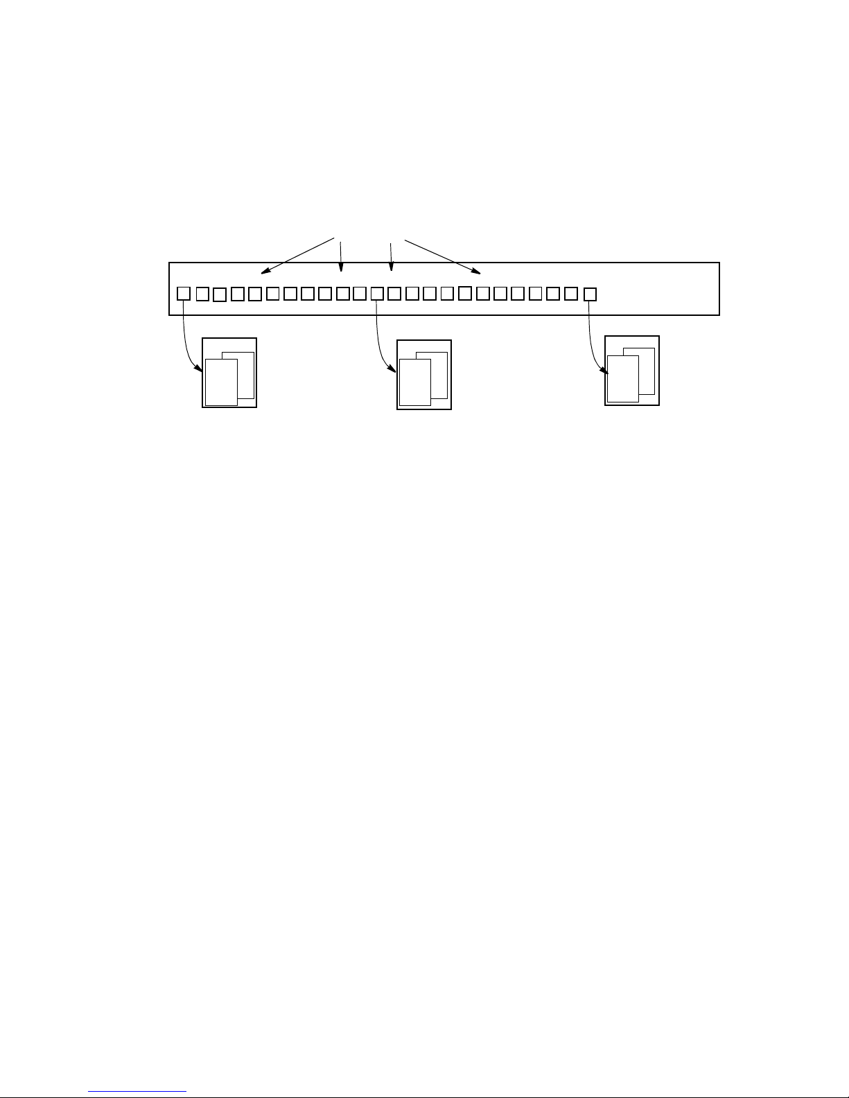
Figure 1-1 shows the 5100/6100 voice ports, voice port numbers, TCID numbers, and coding
profiles.
Figure 1-1. Relationship between voice ports, TCID, and coding profiles
Activating and storing configurations
When a command is issued, it is placed in a temporary storage area where it can be stored or
removed by user operation. To implement a change, that command must be stored in Flash
memory with the activate command and then stored in the configuration file with a commit
command so when the VDR is rebooted it is part of the current configuration. When a sequence
of commands is entered and processed, it changes the values of the affected parameters in a
temporary area, but this does not affect current operation which uses values in the active area.
When you issue the activate command, the new configuration data is moved from the temporary
area to the active area, where it can actually be used. Thus a user can make multiple changes in the
temporary area, for example, using set coding commands, then put them into use with a single
activate command.
Use the activate command only between calls since when it is invoked, it tears down (disrupts)
any calls that are in progress.
Configuration data in the active area is only available while the software platform remains in
operation. If the reset command is issued, or if the platform is manually reset, the active area is
reloaded from the data stored in Flash memory. Data in the active area may be saved to Flash
memory by entering the commit command.
Evaluating call quality
A key feature of the VDR’s support for MGCP is the Call Detail Record (CDR) functionality.
CDR records every successful phone call which is placed through the VDR. Each successful
phone call will have one record in the CDR list. The System Administrator can extract and review
detailed records concerning phone quality and also can access these records for billing purposes.
1
2
3
4
5
6
7
8
9
10
11
12
13
14 15
16
171819 20
21
22 23 24
TCID 0
TCID 23
TCID 11
Coding profile 1
voice
fax
voice
voice
fax
fax
Coding profile 1
Coding profile 1
2
2
2
5100/6100 VDR
voice ports

Accessing MGCP commands
Vpacket 5100/6100 Series MGCP Telephony 7
Accessing MGCP commands
MGCP commands are available within the command line interface (CLI) under the telephony
command shell. Once you establish connectivity to the 5100/6100 VDR either through a
HyperTerminal session or a telnet session, you can access the telephony shell by entering tel and
pressing the Enter key (Figure 1-2).
Figure 1-2. Entering the telephony command shell
Accessing the help feature
Once inside the telephony command shell, you can view a listing of MGCP commands by
entering either the set or show keywords (Figure 1-3).
Figure 1-3. Viewing MGCP help
If you enter a two word combination, you can view the entire list of available commands within
that group. The list contains both basic and advanced commands; so, it is possible to change
parameters that might adversely affect a network.
The commands are listed by group:
• Show commands
• Coding profile parameter command
• TCID parameter commands (including loop start options)
• MGCP parameter commands
• Call quality commands
VPacket# tel
telephony#
VPacket# tel
telephony# set
set tcid
set coding
set xgcp
VPacket#

CHAPTER 1
About MGCP
8 Vpacket 5100/6100 Series MGCP Telephony
Viewing the DSP version
You can view a character string that identifies the DSP software version by issuing the show
dsp_version command.
Syntax: show dsp_version [dsp]
Argument:
dsp the number of the DSP about which you want to view information
Example:
In this example, the DSP information is displayed.
MXP>show dsp_version 1
DSP Version: 6.2.3.107, Voice & Fax, @Small, C548F/C549F, Codecs 0xffd2, Features
0x1fe

Coding profile
commands
Contents
2
Overview, page 11
Recommended FAX settings, page 12
Coding profile commands, page 12

CHAPTER 2
10 Vpacket 5100/6100 Series MGCP Telephony

Vpacket 5100/6100 Series MGCP Telephony 11
Overview
Note. If you are using MGCP with a digital T1 port, you need to set the T1 parameters
before setting any coding profile, TCID, or MGCP commands.
Coding profile commands are used for setting up voice and fax services. These commands allow
you to customize:
• type and usage parameters
• VAD-related parameters
• Echo canceller-related parameters
Voice Activation Detection (VAD) allows a data network carrying voice traffic over the Internet
to detect the absence of audio and conserve bandwidth by preventing the transmission of “silent
packets” over the network. Most conversations include about 50% silence; VAD (also called
“silence suppression”) can be enabled to monitor signals for voice activity so that when silence is
detected for a specified amount of time, the application informs the Packet Voice Protocol and
prevents the encoder output from being transported across the network.
Caution. Before using any MGCP commands, Vpacket strongly recommends that you
prepare a backup configuration of your installation as you have benchmarked it.
Echo canceller commands define the characteristics for controlling voice degradation, adjusting
the filter drift, and managing the echo cancelling features.
Caution. Before using any MGCP commands, Vpacket strongly recommends that you
prepare a backup configuration of your installation as you have benchmarked it.
!
!

CHAPTER 2
12 Vpacket 5100/6100 Series MGCP Telephony
Recommended FAX settings
The recommended fax settings (G.711) for a coding profile are as follows:
• set coding 11 copyof 0
• set coding 11 usage fax on
• set coding 11 usage voice off
• set coding 11 vad off
• set coding 11 nom_delay 80
• set coding 11 max_delay 160
• set coding 11 adaptive_playout off
• set coding 11 tone_detect off
The number 11 (eleven) is a place holder indicating the profile number. You can choose a
different number. In addition to these commands, you also need to assign the fax coding profile to
a TCID (set tcid 0 fax_prof 11) and set the following MGCP command: set xgcp fax_support
local. After the settings are configured, you need to activate and commit the changes.
Coding profile commands
Table 2-1 lists the coding profile commands for an MGCP environment.
Table 2-1. Coding profile commands
Table 2-2.
Command See...
set coding [prof_id] coding_type page 13
set coding [prof_id] usage page 14
show coding page 15
set coding [prof_id] vif page 17
set coding [prof_id] nom_delay page 19
set coding [prof_id] max_delay page 19
set coding [prof_id] adaptive playout page 20
set coding [prof_id] dtmf_relay page 21

Coding profile commands
Vpacket 5100/6100 Series MGCP Telephony 13
Caution. Before using any MGCP commands, Vpacket strongly recommends that
you prepare a backup configuration of your installation as you have benchmarked it.
Some commands that appear in the help should not be altered. The 5100/6100 VDR allows you
to set these some of these parameters, but the choices you configure will not impact the function
of the 5100/6100 VDR because the choices are either not applicable to the 5100/6100 VDR
(some modem or telephone features) or the choices are not yet supported by the system.
One unalterable command exists: set coding [prof_id] ec_cfg <nlp_fix|4w_det>; nlp_fix is the
valid choice; 4w_det is not a valid choice
Unsupported or nonapplicable commands include:
• set coding [prof_id] xfer [g729|g727|pcm|fax]; Frame Relay is not supported
• set coding [prof_id] blocksplit [on|off]; Frame Relay and G.727 are not supported
• set coding [prof_id] enhbits <bits>; G.727 is not supported
• set coding [prof_id] v18_tone_detect [on|off]
• set coding [prof_id] ss7_cot_tone_detect [on|off]
• set coding [prof_id] sf_sig_tone_detect [on|off]
• set coding [prof_id] modem_tx_level <value -- In dB (0 to -13)>
• set coding [prof_id] modem_cd_threshold <0=-26dBm,1=-33dBm, 2=-43dBm>
• set coding [prof_id] modem_cd_threshold <0=-26dBm,1=-33dBm, 2=-43dBm>
Assigning codecs to coding profiles
You can specify the codec type for a coding profile by issuing the set coding command.
Syntax: set coding [prof_id] coding_type [tx|rx] <codec type>
Argument:
tx|rx (optional) choice of transmit (tx) or receive (rx)
codec type Refer to Table 2-3.
Table 2-3. Codec parameter names and descriptions
Codec Type/parameter Description
pcm_mu PCM u-Law coding
pcm_a PCM a-Law coding
a16 ADPCM 16kbps coding
a24 ADPCM 24kbps coding
!

CHAPTER 2
14 Vpacket 5100/6100 Series MGCP Telephony
Example:
In this example, the telephony submenu is accessed and then the coding command is entered. The
5100/6100 VDR responds to confirm the action.
Setting the coding usage
You can set the coding usage by issuing the set coding [prof_id] usage command.
Syntax: set coding [prof_id] usage [voice | fax | modem | data] [on | off]
Arguments:
voice | fax | modem | data
choice of usage
on | off enable or disable usage
Example:
a32 ADPCM 32kbps coding
a40 ADPCM 40kbps coding
g723_53 G.723.1 5.3 kbps coding
g723_63 G.723.1 6.3 kbps coding
g729ab G.729 annex a, annex b 8kbps coding
fax Fax relay
fax_t38 Fax relay in T.38 mode
clear_chan PCM with no other processing (VAD, ECU, etc.)
VPacket# tel
telephony# set coding 1 coding_type pcm_mu
OK
telephony#
VPacket# tel
telephony# set coding 1 usage voice on
OK
telephony#
Table 2-3. Codec parameter names and descriptions
Codec Type/parameter Description

Coding profile commands
Vpacket 5100/6100 Series MGCP Telephony 15
Viewing coding profiles
To view all of the coding profiles, you can issue the show coding command; to view only one,
you can enter a profile number after the command.
Syntax: show coding [prof_ id]
Argument:
prof_id limits the command to showing the requested coding profile
Example:
VPacket# tel
telephony# show coding
Configuration for coding profile id 0:
Tx Coding = G.711 MU
Rx Coding = G.711 MU
Coding profile for voice
Tx VIF size = 640 (bits)
Rx VIF size = 640 (bits)
VAD = ENABLED
VAD threshold = 0 (dB) (relative to ref level of -30dBm)
Playout nominal delay = 30 (msec)
Playout maximum delay = 60 (msec)
Adaptive Playout = ENABLED
Rate = 14400
DTMF Relay = ENABLED
Tone detect = ENABLED
Call Progress Tone detect = DISABLED
V.18 Tone detect = DISABLED
SS7 COT Tone detect = DISABLED
SF Sig Tone detect = DISABLED
EC = ENABLED
EC NL = ENABLED
EC NL Sens = 327
EC Tail = 16 (msec)
EC Refresh = UPDATE
EC Coeffs = RESET
Modem TX level = -13 (dB)
Modem CD threshold = 0
Modem no activity timeout = 20 (sec)
Silence detection time = 60 (msec)
Silence detection level = -50 (dB)
Fax debug level = 0
Caller ID Support = ENABLED
Resampling = DISABLED
EC Config = NLP_FIXED
NLP Confort Noise = 65496
Encapsulation = RTP

CHAPTER 2
16 Vpacket 5100/6100 Series MGCP Telephony
In this example, the coding profile numbered 0 is shown. This profile shows these parameters:
• the transmit coding is set to G.711 Mu
• the receive coding is set to G.711 Mu
• Type of coding profile (in this case, voice)
• the transmit Voice Information Field (VIF) size in bits
• the receive VIF size in bits
•VAD enabled
•VAD threshold
• Playout nominal delay
• Playout maximum delay
• Adaptive playout is enabled
• Rate is set to 14400
• DTMF relay is enabled
• Tone detect is enabled
• Call progress tone detect is disabled
• V.18 is disabled
• SS7 is disabled
• SF signal tone detect is disabled
• Echo canceller (EC) is enabled
• EC NL is enabled
• EC NL sensitivity is set to 327
• EC tail is set to 16 ms
• EC refresh is set to update
• EC coefficients is set to reset
• Modem transmit level is set to -13 dB
• Modem CD threshold is set to zero
• Modem time-out is set to 20 seconds
• Silence detection is set to 60 ms
• Silence detection level is set to -50 dB
• Fax debug level is set to zero
• Caller ID support is enabled
• Resampling is disabled
• EC config is NLP fixed

Coding profile commands
Vpacket 5100/6100 Series MGCP Telephony 17
• NLP comfort noise is 65496
• Encapsulation is set to RTP
Setting the voice information field
You can sets the size (in bits) of the Voice Information Field (VIF) for a coding profile. The
appropriate VIF sizes are related to the coding type. In Table 2-4, a VIF Size value is valid if a
table entry shows the equivalent packet time (in milliseconds); empty entries are not valid.Table 25 lists anticipated packet delay as compared to VIF size and codec.
Table 2-4. Voice coding algorithms
VIF
size
in
bits
Voice coding algorithms
G.726 G.729A G.723.1 G.711
16 kbps
3
24 kbps
3
32 kbps
40 kbps
3
8 kbps 5.3 kbps 6.3 kbps 64 kbps
80
5 ms
4
———10 ms———
120 —
5 ms
4
— — — ———
160 10 ms —
5 ms
4
— 20 ms — — —
192—————30 ms30 ms—
200
15 ms
4
——
5 ms
4
— ———
240 — 10 ms — — 30 ms — — —
320 20 ms — 10 ms — 40 ms — — —
360 —
15 ms
4
— — — ———
384—————60 ms60 ms—
400
25 ms
4
— — 10 ms 50 ms — — —
480 30 ms 20 ms
15 ms
4
— 60 ms — — —
560 — — — — 70 ms — — —
600 —
25 ms
4
— 15 ms — — — —
640 — — — 20 ms — — — 10 ms
720 — 30 ms — — — — — —

CHAPTER 2
18 Vpacket 5100/6100 Series MGCP Telephony
Syntax: set coding [prof_id] vif [tx|rx] <vif size in bits>
Argument:
tx|rx (optional) indicates transmit or receive
VIF size in bits See Table 2-3.
Example:
In this example, the VIF is set for 480 bits.
800 — —
25 ms
4
20 ms — — — —
960 — — 30 ms — — — — —
1000 — — —
25 ms
4
— ———
1200 — — — 30 ms — — — —
1280———————20 ms
1920———————30 ms
3= If encapsulation type is RTP, dynamic payload type is required
4= G.726, G.727 VIF sizes5ms, 15ms, 25ms are available only in restricted builds
VPacket# tel
telephony# set coding 1 vif 480
OK
telephony#
Table 2-4. (continued) Voice coding algorithms
VIF
size
in
bits
Voice coding algorithms
G.726 G.729A G.723.1 G.711
16 kbps
3
24 kbps
3
32 kbps
40 kbps
3
8 kbps 5.3 kbps 6.3 kbps 64 kbps

Coding profile commands
Vpacket 5100/6100 Series MGCP Telephony 19
Setting the nominal delay (jitter)
Jitter is the deviation in (or displacement of) some aspect of the pulses in a high-frequency digital
signal. This deviation is in terms of amplitude, phase timing, or the width of the signal pulse.
Among the causes of jitter are electromagnetic interference (EFI) and crosstalk with other signals.
Jitter can cause a display monitor to flicker; affect the ability of the processor in a personal
computer to perform as intended; introduce clicks or other undesired effects in audio signals, and
loss of transmitted data between network devices.
You can set the nominal delay in milliseconds by issuing the set coding [prof_id] nom_delay
command.
Syntax: set coding [prof_id] nom_delay <value in ms>
Argument:
value in ms delay value
Example:
In this example, the nominal delay is set to 60 ms.
Setting the maximum delay (jitter)
Table 2-5 lists the (absolute) maximum delays. The nominal delay should be at least twice the
packet time (in milliseconds); the packet time corresponds to the VIF value chosen with the codec
types that are displayed in Table 2-3 on page 13.
Note. The maximum delay should be at least twice the nominal delay.
For example, if you selected a VIF of 640 bits per second and the G.711 codec, you would
anticipate a nominal delay of 10 milliseconds (ms). When you double the 10 ms, you know to set
the maximum delay to 20 milliseconds.
VPacket# tel
telephony# set coding 0 nom_delay 60
OK
telephony#
Table 2-5. Delay for coding types
Coding Maximum delay
G.729A 500 ms
G.723.1 (5.3 kbps, 6.3 kbps) 500 ms

CHAPTER 2
20 Vpacket 5100/6100 Series MGCP Telephony
You can set the maximum delay for a coding profile by issuing the set coding [prof_id]
max_delay command.
Syntax: set coding [prof_id] max_delay <value in ms>
Argument:
value in ms value of delay
Example:
In this example, the maximum delay is set to 120 ms.
Setting the adaptive playout function
You can enable or disable the adaptive playout function by issuing the set coding [prof_id]
adaptive playout command.
Syntax: set coding [prof_id] adaptive playout [on|off]
Argument:
on|off enable or disables adaptive playout
Example:
In this example, the adaptive playout function is activated.
G.726, G.727 32 kbps 290 ms
G.711a, G.711m 64 kbps 160 ms
VPacket# tel
telephony# set coding 1 max_delay 120
OK
telephony#
VPacket# tel
telephony# set coding 0 adaptive_playout on
OK
telephony#
Table 2-5. (continued) Delay for coding types
Coding Maximum delay

Coding profile commands
Vpacket 5100/6100 Series MGCP Telephony 21
Setting the DTMF relay mode
You can select the DTMF Relay mode for a TCID, in which DTMF tones are detected during
voice processing and separately packetized for transmission, by issuing the set coding [prof_id]
dtmf_relay command. This is only available with FRF.11 or RTP encapsulation.
Syntax: set coding [prof_id] dtmf_relay [on|off]
Argument:
on|off enables or disables DTMF relay
Example:
In this example, TCID 0 is set to accept DTMF tones.
Setting the VAD mode
Voice Activation Detection (VAD) allows a data network carrying voice traffic over the Internet
to detect the absence of audio and conserve bandwidth by preventing the transmission of “silent
packets” over the network. Most conversations include about 50% silence; VAD (also called
“silence suppression”) can be enabled to monitor signals for voice activity so that when silence is
detected for a specified amount of time, the application informs the Packet Voice Protocol and
prevents the encoder output from being transported across the network.
Caution. Before using any MGCP commands, Vpacket strongly recommends that
you prepare a backup configuration of your installation as you have benchmarked it.
You can set the Voice Activity Detector (VAD) mode for a coding profile by issuing the set
coding [prof_id] vad command.
Syntax: set coding [prof_id] vad [on|off]
Argument:
on|off enables or disables VAD
Example:
In this example, the VAD mode is enabled.
VPacket# tel
telephony# set coding 0 dtmf_relay on
OK
telephony#
VPacket# tel
telephony# set coding 1 vad on
OK
telephony#
!

CHAPTER 2
22 Vpacket 5100/6100 Series MGCP Telephony
Setting an audio threshold
You can set the audio threshold level for the VAD for a coding profile by issuing the set coding
[prof_id] vad_thresh command.
Syntax: set coding [prof_id] vad_thresh <value>
Argument:
value in dBm, -20 to +10, or 32767 for adaptive VAD
Example:
In this example, the VAD audio threshold is set for -10 dBm.
Setting the silence detect time
You can set the silent time for declaring silence detection for a coding profile by issuing the set
coding [prof_id] silence_detect time command.
Syntax: set coding [prof_id] silence_detect time <silent time>
Argument:
silent time in ms; 0 disables silence detect time
Example:
In this example, the silence detection time is set for 2000 ms.
VPacket# tel
telephony# set coding 0 vad_thresh -10
OK
telephony#
VPacket# tel
telephony# set coding 0 silence_detect time 2000
OK
telephony#

Coding profile commands
Vpacket 5100/6100 Series MGCP Telephony 23
Setting a silence detection level
You can set a “silence” signal level for declaring silence detection for a coding profile by issuing
the set coding [prof_id] silence_detect level command.
Syntax: set coding [prof_id] silence_detect level <level>
Argument:
level in dB; valid levels -40 to -50
Example:
In this example, the silence detection level is set to -43 dB.
Setting tone detection
This command controls tone detection which allows switchover. You can enable switchover by
issuing the set coding [prof_id] tone_detect command.
Syntax: set coding [prof_id] tone_detect [on|off]
Argument:
on|off Tone_detect has to be ON in the voice profile if a fax/modem
switchover is desired, since switchover relies on tone detection. For a fax
profile, it does not matter if it is on or off.
Example:
In this example, the tone detection function is enabled because the coding profile is a voice
profile.
VPacket# tel
telephony# set coding 1 silence_detect level -43
OK
telephony#
VPacket# tel
telephony# set coding 0 tone_detect on
OK
telephony#

CHAPTER 2
24 Vpacket 5100/6100 Series MGCP Telephony
Enabling or disabling the echo canceller
Echo cannceller commands define the characteristics for controlling voice degradation, adjusting
the filter drift, and managing the echo cancelling features.
Caution. Before using any MGCP commands, Vpacket strongly recommends that
you prepare a backup configuration of your installation as you have benchmarked it.
You can enable or disable the echo canceller (EC) mode for a coding profile by issuing the set
coding [prof_id] ec command.
Syntax: set coding [prof_id] ec [on|off]
Argument:
on|off on enables the EC; off disables the EC
Example:
In this example, the echo canceller is enabled.
Setting the processor mode for the echo canceller
You can set the Non-Linear Processor mode of the echo canceller (EC) for a coding profile by
issuing the set coding [prof_id] ec_nl command. This command only has an effect if the Echo
Canceller is enabled.
Syntax: set coding [prof_id] ec_nl [on|off]
Argument:
on|off enables or disables the processor mode for EC
Example:
In this example, the processor mode is enabled.
VPacket# tel
telephony# set coding 0 ec on
OK
telephony#
VPacket# tel
telephony# set coding 0 ec_nl on
OK
telephony#
!

Coding profile commands
Vpacket 5100/6100 Series MGCP Telephony 25
Setting the echo canceller tail length
You can set the echo canceller (EC) tail length–the maximum echo value that the EC will cancel–
for a coding profile by issuing the set coding [prof_id] ec_tail command.
Syntax: set coding [prof_id] ec_tail <value in ms>
Argument:
value in ms
Valid values for the tail length depend upon the codecs available and the number of channels
configured in the DSP.
Example:
In this example, the echo tail length is set to 16 ms.
Setting the echo canceller processor value
You can set the sensitivity of the EC non-linear processing (NLP) values by issuing the set
coding [prof_id] ec_nlp_sens command.
Syntax: set coding [prof_id] ec_nlp_sens <value>
Argument:
value 0 through 32767; Default is 327
Example:
In this example, the echo canceller processor sensitivity value is set to 327.
VPacket# tel
telephony# set coding 0 ec_tail 16
OK
telephony#
VPacket# tel
telephony# set coding 0 ec_nlp_sens 327
OK
telephony#

CHAPTER 2
26 Vpacket 5100/6100 Series MGCP Telephony
Setting the refresh state
You can set the EC refresh state to remain frozen or refresh by issuing the set coding [prof_id]
ec_refresh command.
Syntax: set coding [prof_id] ec_refresh [freeze | update]
Argument:
freeze | update freeze does not update; update allows the EC to refresh
Example:
In this example, the EC is set to freeze and will not refresh the state.
Setting the echo canceller refresh coefficient
You can enable or disable the EC coefficient to refresh state by issuing the set coding [prof_id]
ec_coeffs command.
Syntax: set coding [prof_id] ec_coeffs [reset | normal]
Argument:
reset | normal
Example:
In this example, the EC is set to reset itself.
VPacket# tel
telephony# set coding 0 ec_refresh freeze
OK
telephony#
VPacket# tel
telephony# set coding 0 ec_coeffs reset
OK
telephony#

Contents
3
Overview, page 29
TCID commands, page 29
Required TCID commands, page 31
TCID FXS loopstart, page 33
Miscellaneous TCID parameters, page 35
TCID commands

CHAPTER 3
TCID commands
28 Vpacket 5100/6100 Series MGCP Telephony

TCID commands
Vpacket 5100/6100 Series MGCP Telephony 29
Overview
TCIDs are typically configured with the following information:
• A preferred coding profile to use for voice
• An alternate coding profile to switch to when FAX tones are detected
• Other possible coding profiles to use if the preferred voice profile can’t be negotiated
• Additional local configuration parameters
The following sections contain each command with a definition, parameters, and an example to
show how to modify an existing TCID channel description or build a new one.
• The set tcid commands describe and modify the local configuration parameters of the TCID
channel as a whole.
• The set coding commands describe and modify the coding profile attached to the TCID.
• The set xgcp commands to modify the MGCP parameters pertaining to the TCID.
Caution. Before using any TCID modification commands, Vpacket strongly
recommends that you prepare a backup configuration of your installation as you
have benchmarked it.
The TCID commands describe and modify the local configuration parameters of the TCID
channel as a whole.
TCID commands
Table lists the TCID-related commands for an MGCP environment.
!
Table 3-1. TCID commands
Required TCID parameters set tcid [tcid] voice_prof page 31
set tcid [tcid] notify_entity <IP_Address [:port]>
<dynamic| static>
page 31
set tcid [tcid] endpoint_id <string> page 32

CHAPTER 3
TCID commands
30 Vpacket 5100/6100 Series MGCP Telephony
Some commands that appear in the help should not be altered. The 5100/6100 VDR allows you
to set these some of these parameters, but the choices you configure will not impact the function
of the 5100/6100 VDR because the choices are either not applicable to the 5100/6100 VDR
(some modem or telephone features) or the choices are not yet supported by the system.
Unsupported or nonapplicable commands include:
• set tcid [tcid] out_type [tone|pulse]
• set tcid [tcid] aer_output <handset|handsfree>
TCID FXS loopstart set tcid [tcid] fxsls offhook_db page 33
set tcid [tcid] fxsls onhook_db page 33
set tcid [tcid] fxsls seize_detect page 34
set tcid [tcid] fxsls orig_clear_detect page 34
set tcid [tcid] fxsls answ_clear_detect page 35
Miscellaneous TCID
parameters
set tcid [tcid] mode [sw | trans] [cas | ccs | proxy |
xgcp]
page 35
set tcid [tcid] rxgain <value> page 36
set tcid [tcid] txgain <value in dB (-14 to 14)> page 36
set tcid [tcid] idle_noise <signed value in.01 dB> page 36
set tcid [tcid] state [normal|down] page 37
set tcid [tcid] copyof [tcid] page 37
set tcid [tcid] tone_out_on page 38
set tcid [tcid] tone_out_off page 38
set tcid [tcid] call_limit page 38
set tcid [tcid] default_digit_map page 39
set tcid [tcid] default_event_list page 39
set tcid [tcid] partial_digit_timer page 40
set tcid [tcid] critical_digit_timer page 40
set tcid [tcid] service_class page 41
Table 3-1. (continued) TCID commands

Required TCID commands
Vpacket 5100/6100 Series MGCP Telephony 31
• set tcid [tcid] aer_hf_spkr_gain <0-31>
• set tcid [tcid] aer_hs_spkr_gain <0-31>
Required TCID commands
TCIDs are typically configured with the following information:
• A preferred coding profile to use for voice
• An alternate coding profile to switch to when FAX tones are detected
• Other possible coding profiles to use if the preferred voice profile can’t be negotiated
• Additional local configuration parameters
The following sections contain each command with a definition, parameters, and an example to
show how to modify an existing TCID channel description or build a new one.
• The set tcid commands describe and modify the local configuration parameters of the TCID
channel as a whole.
• The set coding commands describe and modify the coding profile attached to the TCID
(page 29).
• The set xgcp commands modify the MGCP parameters pertaining to the TCID (See
page 43).
Caution. Before using any TCID modification commands, Vpacket strongly
recommends that you prepare a backup configuration of your installation as you
have benchmarked it.
The TCID commands describe and modify the local configuration parameters of the TCID
channel as a whole.
Assigning a TCID number and coding profile
You can set the preferred voice coding profile for the TCID by issuing the set tcid [tcid]
voice_prof command. [tcid] is a placeholder for the number of the TCID that you want to set.
Syntax: set tcid [tcid] voice_prof <prof_id>
Argument:
prof_id profile ID number; from 0 to maximum number of profiles -1; -1 means
no preferred profile
!

CHAPTER 3
TCID commands
32 Vpacket 5100/6100 Series MGCP Telephony
Example:
In this example, the preferred voice coding profile for voice port number 1, which is TCID
number 0, is set to coding profile number 1.
Setting the notify entry
You can set the softswitch information by issuing the set tcid [tcid] notify_entry command.
This command defines the address and port of the Call Agent that is to receive call event
information and is set on a per TCID basis.
Syntax: set tcid [tcid] notify_entity <IP_Address [:port]> <dynamic| static>
Argument:
IP_Address:port IP address of the entity to be notified with a port number (optional)
dynamic| static dynamic makes the VDR accept calls from all softswitches; static makes
the 5100/6100 VDR only accept calls from the softswitch identified by
the specified IP address
Example:
In this example, the MGCP call agent is set to the IP address 192.169.5.244 and port 2427. It is a
static setup, which means that the 5100/6100 VDR only accepts calls from that particular Call
Agent.
Setting the TCID endpoint
You can set the MGCP TCID endpoint by issuing the set tcid [tcid] endpoint_id command.
Syntax: set tcid [tcid] endpoint_id <string>
Argument:
string a unique number of 40 alphanumeric characters or fewer assigned by the
softswitch; can include a port number, slot number, circuit number a
combination values
VPacket# tel
telephony# set tcid 0 voice_prof 1
OK
telephony#
telephony# set tcid 1 notify_entity 192.169.5.244:2427 static
OK
telephony#

TCID FXS loopstart
Vpacket 5100/6100 Series MGCP Telephony 33
Example:
In this example, the MGCP endpoint is set to a001.
TCID FXS loopstart
The next section of commands are for FXS loopstart.
Setting the off hook level
You can set the off hook level by issuing the set tcid [tcid] fxsls offhook_db command. This
command applies only to those VDR models with FXS voice interface ports.
Syntax: set tcid [tcid] fxsls offhook_db <value in ms>
Argument:
value in ms
Example:
In this example, the off hook level is set to 3 ms.
Setting the on hook level
You can set the on hook level by issuing the set tcid [tcid] fxsls onhook_db command. This
command applies only to those VDR models with FXS voice interface ports.
Syntax: set tcid [tcid] fxsls onhook_db <value in ms>
Argument:
value in ms
Example:
In this example, the on hook level is set to 5 ms.
telephony# set tcid 1 endpoint_id a001
OK
telephony#
telephony# set tcid 2 fxsls offhook_db 3
OK
telephony#
telephony# set tcid 2 fxsls onhook_db 5
OK
telephony#

CHAPTER 3
TCID commands
34 Vpacket 5100/6100 Series MGCP Telephony
Setting the seize detect parameter
You can set the seize detect parameter by issuing the set tcid [tcid] fxsls seize_detect
command. This command applies only to those VDR models with FXS voice interface ports.
Syntax: set tcid [tcid] fxsls seize_detect <value in ms>
Argument:
value in ms
Example:
In this example, the seize detect is set to 3 ms.
Setting the originator clear detect parameter
You can set the originator clear detect parameter by issuing the set tcid [tcid] fxsls
orig_clear_detect command. This command applies only to those VDR models with FXS voice
interface ports.
Syntax: set tcid [tcid] fxsls orig_clear_detect <value in ms>
Argument:
value in ms
Example:
In this example, the clear originator detect parameter is set to 5 ms.
telephony# set tcid 2 fxsls seize_detect 3
OK
telephony#
telephony# set tcid 2 fxsls orig_clear_detect 5
OK
telephony#

Miscellaneous TCID parameters
Vpacket 5100/6100 Series MGCP Telephony 35
Setting the answer-side clear detect
You can set the answer-side clear detect by issuing the set tcid [tcid] fxsls answ_clear_detect
command. This command applies only to those VDR models with FXS voice interface ports.
Syntax: set tcid [tcid] fxsls answ_clear_detect <value in ms>
Argument:
value in ms
Example:
In this example, the answer-side clear detect is set to 4 ms.
Miscellaneous TCID parameters
The next section contains TCID commands for various features.
Setting the TCID mode
You can set the operating mode for each TCID (0-23) by issuing the set tcid [tcid] mode
command. The mode is set on a per TCID basis.
Syntax: set tcid [tcid] mode [sw | trans] [cas | ccs | proxy | xgcp]
Arguments:
tcid 0-23; the ID number of the TCID you want to
sw |trans sw is softswitch (choice for H.323)
cas | ccs | proxy | xgcp
cas is channel associated signaling (valid); ccs is clear channel signaling;
proxy; xgcp is MGCP (valid)
Example:
In this example, the mode for TCID 4 is set to use MGCP.
telephony# set tcid 2 fxsls answ_clear_detect 4
OK
telephony#
VPacket# tel
telephony# set tcid 4 mode sw xgcp
OK
telephony#

CHAPTER 3
TCID commands
36 Vpacket 5100/6100 Series MGCP Telephony
Setting the receive gain
You can set the receive gain by issuing the set tcid [tcid] rxgain command.
Syntax: set tcid [tcid] rxgain <value>
Argument: <value in dB (-14 to 14)>
Example:
In this example, the receive gain is set to -13 dB.
Setting the transmit gain
You can set the transmit gain value by issuing the set tcid [tcid] txgain command.
Syntax: set tcid [tcid] txgain <value>
Argument:
value in dB (-14 to 14)>
Example:
In this example, the transmit gain is set to 13.
Setting the idle noise
You can set the idle or comfort noise for a TCID by issuing the set tcid [tcid] idle_noise
command.
Syntax: set tcid [tcid] idle_noise <signed value>
Argument:
signed value in 0.01dBm; for example, -5000 = -50dBm
VPacket# tel
telephony# set tcid 0 rxgain -13
OK
telephony#
VPacket# tel
telephony# set tcid 1 txgain 13
OK
telephony#

Miscellaneous TCID parameters
Vpacket 5100/6100 Series MGCP Telephony 37
Example:
In this example, the idle noise is set to -5000 or -50dBm.
Setting the TCID state
If a call is not in progress, you can set the TCID state by issuing the set tcid [tcid] state
command.
Syntax: set tcid [tcid] state [normal|down]
Argument:
normal|down
Example:
In this example, the call state is set to normal.
Copying the settings of one TCID to another TCID
You can copy the settings of a second specified TCID to the first specified TCID by issuing the
set tcid [tcid] copyof command.
Syntax: set tcid [tcid1] copyof [tcid2]
Argument:
tcid1 is the identification number of the target TCID to be copied to
tcid2 is the identification number of the TCID you want to copy
Example:
In this example, the settings of TCID 0 are copied to TCID 1.
VPacket# tel
telephony# set tcid 1 idle_noise -5000
OK
telephony#
VPacket# tel
telephony# set tcid 0 state normal
OK
telephony#
VPacket# tel
telephony# set tcid 1 copyof 0
OK
telephony#

CHAPTER 3
TCID commands
38 Vpacket 5100/6100 Series MGCP Telephony
Setting tone out on
You can set the on-time for DTMF dial tones for a specific TCID by issuing the set tcid [tcid]
tone_out_on command.
Syntax: set tcid [tcid] tone_out_on <time>
Argument:
time in ms
Example:
In this example, the dial tone is set to ring after 200 ms.
Setting tone out off
You can set the off-time for DTMF dial tones for a specific TCID by issuing the set tcid [tcid]
tone_out_off command.
Syntax: set tcid [tcid] tone_out_off <time>
Argument:
time in ms
Example:
In this example, the dial tone is set to stop after 100 ms.
Setting a call length limit
You can set a call length limit for calls for a specific TCID by issuing the set tcid [tcid] call_limit
command. If the call length is exceeded, the call is automatically terminated.
Syntax: set tcid [tcid] call_limit <value>
Argument:
value 0-65535 seconds; -1 or 65535 for infinity
VPacket# tel
telephony# set tcid 1 tone_out_on 200
OK
telephony#
VPacket# tel
telephony# set tcid 0 tone_out_off 100
OK
telephony#

Miscellaneous TCID parameters
Vpacket 5100/6100 Series MGCP Telephony 39
Example:
In this example, the TCID is set to have no call length limit.
Setting the default digit map
You can defines the digit map to be used if the softswitch/Call Agent does not provide one by
issuing the set tcid [tcid] default_digit_map command.
Syntax: set tcid [tcid] default_digit_map <digit_map_string>
Argument:
digit_map_string [0-9]xxx|91x.T|9011x.T] which are defined as:
[0-9]xxx: the bracketed numbers supply a set of valid numbers–
separated by commas–which precede the local dialing number.
91x.T: these parameters allow for a PBX dial-out both locally and across
area codes (the x and the 1, respectively); the “.T” signifies a duration in
seconds during which the digits must be dialed or a fast busy signal
occurs.
9011x.T: these parameters allow for a PBX dial-out for international
calls.
Example:
In this example, the default digit map is set to 0T.
Setting the default event list
You can obtain a default list of detect events by issuing the set tcid [tcid] default_event_list
command.
Syntax: set tcid [tcid] default_event_list <event list string>
Argument:
event list string can be hu, hd, ft, or mt
VPacket# tel
telephony# set tcid 0 call_limit 65535
OK
telephony#
VPacket# tel
telephony# set tcid 1 default_digit_map 0t
OK
telephony#

CHAPTER 3
TCID commands
40 Vpacket 5100/6100 Series MGCP Telephony
Example:
In this example, the event list string is set to hu.
Setting the partial digit timer
You can specify the partial digit timer by issuing the set tcid [tcid] partial_digit_timer
command.
Syntax: set tcid [tcid] partial_digit_timer <time in seconds>
Argument:
time in seconds
Example:
In this example, the partial digit time is set to 16 seconds.
Setting the critical digit timer
You can set the critical digit time by issuing the set tcid [tcid] critical_digit_timer command.
Syntax: set tcid [tcid] critical_digit_timer <time in seconds>
Argument:
time in seconds
Example:
In this example, the critical digit timer is set to 4 seconds.
telephony# set tcid 0 default_event_list hu
OK
telephony#
VPacket# tel
telephony# set tcid 0 partial_digit_timer 16
OK
telephony#
telephony# set tcid 1 critical_digit_timer 4
OK
telephony#

Miscellaneous TCID parameters
Vpacket 5100/6100 Series MGCP Telephony 41
Setting the type of service
You can set the service class ID by issuing the set tcid [tcid] service_class command.
Syntax: set tcid [tcid] service_class <service_class_id>
Argument:
service_class_id 1 to 255
Example:
In this example, TCID number 2 is set for service class 3.
telephony# set tcid 2 service_class 3
OK
telephony#

CHAPTER 3
TCID commands
42 Vpacket 5100/6100 Series MGCP Telephony

Contents
4
MGCP commands
Overview, page 45
MGCP commands, page 45
, page 51

CHAPTER 4
MGCP commands
44 Vpacket 5100/6100 Series MGCP Telephony

MGCP commands
Vpacket 5100/6100 Series MGCP Telephony 45
Overview
You need to prepare the 5100/6100 VDR to qualify as a Client (to the Softswitch as Call Agent).
Note. If you are using MGCP with a digital T1 port, you need to set the T1 parameters
before setting any coding profile, TCID, or MGCP commands.
The 5100/6100 VDR’s local configuration MGCP parameters include both FXS Loop Start
parameters which are not part of the coding profiles and do not need to be identical at both ends
of the call (for each coding profile) and a set called “Other Parameters.”
MGCP commands
Table 4-1 lists MGCP commands.
Table 4-1. MGCP commands
Command See...
set xgcp package_type [1 | 2] page 46
set xgcp RFC2833 [on | off] page 46
set xgcp mgcp_version <#> page 47
show version page 48
show xgcp page 49
set xgcp rgw_name page 50
set xgcp dns_lookup page 50
set xgcp wc_restart page 51
set xgcp persistent_events page 51
set xgcp re_xmit2_limit page 51
set xgcp restart_wait page 52
set xgcp nominal_wait page 53
set xgcp size_history_list page 54
set xgcp ts_max page 54

CHAPTER 4
MGCP commands
46 Vpacket 5100/6100 Series MGCP Telephony
Enabling T1 CAS for MGCP
You can use T1 Channel Associated Signaling (CAS) by issuing the set xgcp package_type
command.
Syntax: set xgcp package_type [1 | 2]
Argument:
1 | 2 1 (Default) supports E&M wink start DTMF trunk as described in
RFC2705 M package; 2 supports E&M wink start DTMF as described
in RFC3064 DT package.
Example:
In this example, E&M wink start DTMF trunk as described in RFC3064 DT package is set.
set xgcp td_init page 55
set xgcp td_max page 55
set xgcp td_min page 56
set xgcp sdp page 56
set xgcp keep_alive page 57
set xgcp cta page 57
VPacket# tel
telephony# set xgcp package_type 2
OK
telephony#
Table 4-1. MGCP commands
Command See...

MGCP commands
Vpacket 5100/6100 Series MGCP Telephony 47
Enabling MGCP to interoperate with a Nuera softswitch
You can enable the ring on/off and hookflash events as defined in RFC2833 by issuing the set
xgcp RFC2833 command. Enabling this command allows the 5100/6100 VDR to interoperate
with a Nuera softswitch.
Syntax: set xgcp RFC2833 [on |off]
Argument:
on | off default = off; on enables this feature
Example:
In this example, ring on/off and the hookflahs event options are enabled as defined by RFC 2833.
Setting the MGCP version
You can define the MGCP version for the TCID by issuing the set xgcp mgcp_version
command.
Syntax: set xgcp mgcp_version [1 | 2]
Argument:
1 | 2 1 = MGCP 1.0; 2 = MGCP NCS 1.0
Example:
In this example, XGCP version is set to MGCP NCS 1.0.
VPacket# tel
telephony# set xgcp rfc2833 on
OK
telephony#
VPacket# tel
telephony# set xgcp mgcp_version 2
OK
telephony#

CHAPTER 4
MGCP commands
48 Vpacket 5100/6100 Series MGCP Telephony
Viewing the MGCP code version
You can view the code version, build characteristics, and DSP configuration by issuing the show
version command.
Syntax: show version
Example:
In this example, the version information is displayed.
ggdbg>show version
TSG Version: R7.0(Build 4)
XGCP Version: R7.0(Build 4)
CM Version Label: 1598-006
TBD-TBD, SUPERCOMBO Build, 500 Ticks/Sec Clock
24 Voice TCIDS, 0 Data TCIDS
System has FLASH
TIU Transitional Polling (0)
DSP Configuration:
DSPs = 2
Channels per DSP = 4
HPI Mapping = 2 (FIFO)
Clock Mult = 10
Fsx Fsr = 24
Pwr Dn Tmr Period = 5000
Wake Up Int Mask = 0
HW Companding = 1
Serial Port Config = 0
Sync Int Config = 1
Clock Out Config = 1
Hint Control = 0x0
BDX Delay Control = 0
HW Gain Control = 1

MGCP commands
Vpacket 5100/6100 Series MGCP Telephony 49
Viewing the current MGCP configuration
You can view the current congfiguration of MGCP by issuing the show xgcp command.
Syntax: show xgcp
Example:
In this example, the MGCP information is displayed.
VPacket# tel
telephony# show xgcp
xGCP Configuration:
Restart Wait: 5 sec
Rexmit retry limit MAX1: 7 retries, DNS re-query enabled
Rexmit retry limit MAX2: 5 retries, DNS re-query enabled
Nominal retry wait : 1000 msec
Ts Max : 20 sec
Size of History List : 30 sec
Our RGW Name :
DNS lookup : (disabled)
Persistent events : (enabled)
MGCP version : MGCP 1.0
Patch wildcard restart : (enabled)
SDP : (basic)
RFC2833 : Off
Td Init : 20 sec
Td Min : 20 sec
Td Max : 20 sec
telephony#

CHAPTER 4
MGCP commands
50 Vpacket 5100/6100 Series MGCP Telephony
Setting the remote gateway name
You can set the name of the remote gateway (5100/6100 VDR) with a DNS name or an IP
address by issuing the set xgcp rgw_name command.
Syntax: set xgcp rgw_name <name string>
Argument:
name string can be up to 40 characters; domain name server [DNS] name or IP
address
Example:
In this example, the remote gateway name is identified by the IP address 192.168.1.66.
Setting the DNS IP address
You can set the IP address for DNS services by issuing the set xgcp dns_lookup command.
Syntax: set xgcp dns_lookup [enable | disable]
Argument:
enable|disable enable activates the lookup feature; disable deactivates the lookup
feature
Example:
In this example, the DNS lookup feature is enabled so that the lookup feature functions.
Note. To use this command to set up the IP address for the DNS in an MGCP
environment, you must first use the set dns_client primary_server <ip address>
command, a command that must be issued at the main CLI command menu level.
VPacket# tel
telephony# set xgcp rgw_name 192.168.1.66
OK
telephony#
VPacket# tel
telephony# set xgcp dns_lookup enable
OK
telephony#

MGCP commands
Vpacket 5100/6100 Series MGCP Telephony 51
Enabling all endpoints to send messages
You can enable the 5100/6100 VDR to send RSIP messages to all endpoints by issuing the set
xgcp wc_restart command.
Syntax: set xgcp wc_restart [enable | disable]
Argument:
enable|disable
Example:
In this example, all endpoints are enabled to receive the RSIP message.
Enabling or disabling recording of events
You can enable or disable recording and reporting all events or the last event during a call by
issuing the set xgcp persistent_events command.
Syntax: set xgcp persistent_events <enable|disable>
Argument:
enable|disable enable forces recording and reporting of all calls;
disable forces recording and reporting of only the last call
Example:
In this example, only the last call is recorded and reported.
Setting the number of transmissions
The number of re-transmissions to the Call Agent before the XGCP Client will query the name
server one more time to detect if any other interface to Call Agent has become available.
Syntax: set xgcp re_xmit1_limit <number of tries> [disable]
Argument:
number of tries 0-5
VPacket# tel
telephony# set xgcp wc_restart enable
OK
telephony#
VPacket# tel
telephony# set xgcp persistent_events disable
OK
telephony#

CHAPTER 4
MGCP commands
52 Vpacket 5100/6100 Series MGCP Telephony
Example:
In this example, the transmit tries are limited to five.
Setting the number of retransmissions
The number of re-transmissions to the Call Agent before the XGCP Client will query the name
server one more time to detect if any other interface to Call Agent has become available.
Syntax: set xgcp re_xmit2_limit <number of retries> [disable]
Argument:
number of retries 0-5
Example:
In this example, the retransmit tries are limited to five.
Setting the restart wait time
You can set the time that the XGCP client waits before it notifies the VDR/Call Agent that it has
restarted by issuing the set xgcp restart_wait command.
Syntax: set xgcp restart_wait <time in secs>
Argument:
time in secs 0-255
Example:
In this example, the XGCP client is set to wait 5 seconds before notifying the 5100/6100 VDR
about a restart.
telephony# set xgcp re_xmit1_limit 5
OK
telephony#
telephony# set xgcp re_xmit2_limit 5
OK
telephony#
telephony# set xgcp restart_wait 5
OK
telephony#

MGCP commands
Vpacket 5100/6100 Series MGCP Telephony 53
Setting the nominal wait time
You can set the average re-transmission time value by issuing the set xgcp nominal_wait
command.
Syntax: set xgcp nominal_wait <time in ms>
Argument:
time in ms limit in excess of 100,000,000 ms
Example:
In this example, the nominal wait time is set to 1000 ms.
telephony# set xgcp nominal_wait 1000
OK
telephony#

CHAPTER 4
MGCP commands
54 Vpacket 5100/6100 Series MGCP Telephony
Setting a history limit
You can set the number of seconds that responses to old transactions must be kept in the history
list by issuing the set xgcp size_history_list command.
Syntax: set xgcp size_history_list <time in secs>
Argument:
time in secs
Example:
In this example, the history list will be kept for 30 seconds.
Setting the maximum retry
You can set the maximum amount of time to retry sending a message to a Call Agent by issuing
the set xgcp ts_max command.
Syntax: set xgcp ts_max <time in secs>
Argument:
time in secs must be less than size-history-list
Example:
In this example, the Call Agent will retry to send a message for a maximum of 20 seconds.
telephony# set xgcp size_history_list 30
OK
telephony#
telephony# set xgcp ts_max 20
OK
telephony#

MGCP commands
Vpacket 5100/6100 Series MGCP Telephony 55
Setting the initial time-out delay
You can set the initial time-out delay before attempting to reconnect following a disconnect from
the call agent by issuing the set xgcp td_init command. The default time-out delay is 15 seconds.
Syntax: set xgcp td_init <time in secs>
Argument:
time in secs
Example:
In this example, the initial time-out delay is set to 20 seconds.
Setting the maximum time delay before a reconnect
You can set the maximum time delay before attempting to reconnect following a disconnect from
the call agent by issuing the set xgcp td_max command. The default maximum time-out delay is
600 seconds.
Syntax: set xgcp td_max <time in seconds>
Argument:
time in seconds
Example:
In this example, the maximum time delay is set to 20 seconds.
telephony# set xgcp td_init 20
OK
telephony#
telephony# set xgcp td_max 20
OK
telephony#

CHAPTER 4
MGCP commands
56 Vpacket 5100/6100 Series MGCP Telephony
Setting the minimum time delay before a reconnect
You can set the minimum time delay before attempting to reconnect following a disconnect from
the call agent by issuing the set xgcp td_min command. The default minimum time delay is 15
seconds.
Syntax: set xgcp td_min <time in seconds>
Argument:
time in seconds
Example:
In this example, the minimum time delay is set to 20 seconds.
Enabling event recording
You can enable basic or full recording and recording and reporting of Session Description
Protocol events by issuing the set xgcp sdp command.
Syntax: set xgcp sdp [basic|full]
Argument:
basic|full
Example:
In this example, basic recording is enabled.
telephony# set xgcp td_min 20
OK
telephony#
telephony# set xgcp sdp basic
OK
telephony#

MGCP commands
Vpacket 5100/6100 Series MGCP Telephony 57
Enabling or disabling keep alive messages
You can set the 5100/6100 VDR to send an RSIP message to the Call Agent (CA) by issuing the
set xgcp keep_alive command. When enabled, this command enables the 5100/6100 VDR to
send an RSIP message to the CA if the CA does not send a message within 2.5 minutes. The
message sent by the CA does not have to be an audit endpoint message. The keep alive feature
allows the 5100/6100 VDR to detect connection loss within a maximum of five minutes. The
RSIP message is only sent on idle ports; if a call is active, the message is not sent.
Note. A flash clean is recommended before using this command. After configuring
this command to “on,” you need to activate, commit and then reset the 5100/
6100 VDR.
Syntax: set xgcp keep_alive [on | off]
Argument:
on | off default = off; on enables the 5100/6100 VDR to send an RSIP message
Example:
In this example, the 5100/6100 VDR is set to send an RSIP message to the CA if no
communication from the CA is received within 2.5 minutes.
Setting the connection type attribute
You can enable or disable the connection type attribute (CTA) by issuing the set xgcp cta
command. The CTA parameter allows interoperability with BroadSoft.
Syntax: set xgcp cta <on|off>
Argument:
on | off on enables the CTA feature; off disables the CTA feature
Example:
In this example, the 5100/6100 VDR is set for interoperability with BroadSoft products.
telephony# set xgcp keep_alive on
OK
telephony#
telephony# set xgcp cta on
OK
telephony#

CHAPTER 4
MGCP commands
58 Vpacket 5100/6100 Series MGCP Telephony

Contents
5
T1 interface commands
Overview, page 61
T1 voice interface commands, page 61

CHAPTER 5
T1 interface commands
60 Vpacket 5100/6100 Series MGCP Telephony

T1 voice interface commands
Vpacket 5100/6100 Series MGCP Telephony 61
Overview
The commands in this chapter apply only to 6100 VDR models that have a digital T1 port for
voice (T1-CAS). From within the telephony shell, you can access the T1 commands necessary for
configuring digital voice over a T1 port with channel associated signaling (CAS). The T1-CAS
port can be configured by using the T1-CAS commands.
After configuring the T1-CAS port, you can set the endpoints and port numbers, for the E&M
wink start option, by using the basic MGCP commands (See page 45).
Note. If, after customizing the T1 configuration, you use the flashclean command, all
T1 settings will return to the default settings.
For 5100/6100 VDR models with a digital T1 voice port, the following parameters must be set
prior to use:
•frame mode
• linecoding
•clock source
• loopback source
T1 voice interface commands
Table 5-1 lists the T1 parameter and interface monitoring commands found within this chapter.
From within the telephony shell, you can access the T1 commands necessary for configuring
digital voice over a T1 port with channel associated signaling.
Table 5-1. T1 voice interface commands
Command See...
show t1 page 62
set t1 framemode [ESF|D4] page 62
set t1 linecoding [B8ZS|AMI] page 63
set t1 clocksource [internal|network] page 63
set t1 loopback [noloopback|payload|line] page 64

CHAPTER 5
T1 interface commands
62 Vpacket 5100/6100 Series MGCP Telephony
Note. If, after customizing the T1 configuration, you use the flashclean command, all
T1 settings will return to the default settings.
Viewing the T1 configuration settings
You can view the T1 configuration settings by issuing the show t1 command.
Syntax: show t1
Example:
In this example, the T1 parameters are shown.
Setting the T1 frame mode
You can set the T1 frame mode by issuing the set t1 framemode command.
Syntax: set t1 framemode [ESF|D4]
Arguments:
ESF
D4
Example:
In this example, the T1 frame mode is set to ESF.
VPacket# tel
telephony# show t1
T1 Configuration :
Frame mode : ESF
Line coding : B8ZS
Clock source : network
Loopback mode : noloopback
telephony#
VPacket# tel
telephony# set t1 framemode esf
OK
telephony#

T1 voice interface commands
Vpacket 5100/6100 Series MGCP Telephony 63
Setting the T1 line coding
You can set the T1 line coding by issuing the set t1 linecoding command.
Syntax: set t1 linecoding [B8ZS|AMI]
Arguments:
B8ZS
AMI
Example:
In this example, the T1 linecoding is set to B8ZS.
Setting the T1 clock source
You can set the T1 clock source to either internal time keeping or from the network by issuing the
set t1 clocksource command.
Syntax: set t1 clocksource [internal|network]
Argument:
internal | network internal sets the VDR to use the internal clock for time keeping;
network forces the VDR to use the network clock
Example:
In this example, the T1 port is configured to use the network clock for time keeping.
VPacket# tel
telephony# set t1 linecoding B8ZS
OK
telephony#
VPacket# tel
telephony# set t1 clocksource network
OK
telephony#

CHAPTER 5
T1 interface commands
64 Vpacket 5100/6100 Series MGCP Telephony
Setting the T1 loopback
You can set the T1 loopback by issuing the set t1 loopback command.
Syntax: set t1 loopback [noloopback|payload|line]
Argument:
noloopback | payload | line
Example:
In this example, the T1 port is configured to no loopback.
VPacket# tel
telephony# set t1 loopback noloopback
OK
telephony#

Contents
6
Voice quality commands
Overview, page 67
Call quality commands, page 67

CHAPTER 6
Voice quality commands
66 Vpacket 5100/6100 Series MGCP Telephony

Call quality commands
Vpacket 5100/6100 Series MGCP Telephony 67
Overview
MGCP support includes Call Detail Record (CDR) functionality. CDR records every successful
phone call which is placed through the 5100/6100 VDR. Each successful phone call will have one
record in the CDR list. The system administrator can extract and review detailed records
concerning phone quality and also can access these records for billing purposes.
Call quality commands
Table 6-1 lists the call quality commands.
Enabling the call detail records feature
You can enable the call detail record (CDR) feature by issuing the cdr command.
Syntax: cdr [on | off]
Argument:
on | off the default is “on”; on enables CDR; off disables the CDR
Example:
In this example, the CDR feature is disabled.
Viewing the call detail record
You can view the CDR entries to evaluate call quality by issuing the cdr list command.
Syntax: cdr list [record_no]
Table 6-1. Call quality commands
Command See...
cdr page 67
cdr list <number> page 67
cdr clean page 68
cdr stats page 69
VPacket# tel
telephony# cdr off
OK
telephony#

CHAPTER 6
Voice quality commands
68 Vpacket 5100/6100 Series MGCP Telephony
Argument:
record_no the number of a specific call record that you want to view
Example:
In this example, a specific call record number is not entered. As a result, all CDR entries include:
• an ID for each call (a unique number assigned on a per-session basis)
• the TCID assigned to the call
• Date, Start (Starting Time) and Dur(ation) timestamps
• Dly (delay in making the round-trip, measured in milliseconds)
• Jitter (in milliseconds)
• Pkg (percentage of the packets lost during transmission)
• Coder (the codec assigned to the traffic flow)
• Vqs (the numerical quality of the Voice Quality Service measurement)
• Fjit (the measured Far-End Jitter)
• FPkg (Far-End Packet percentage loss)
• FVqs (Far-End Voice Quality Service measurement)
Deleting CDR information from the Flash memory
You can delete the CDR information from the Flash memory by issuing the cdr clean command.
Syntax: cdr clean
Example:
In this example, all previously stored CDR information is deleted from the Flash memory.
.
telephony# cdr list
ID TCID Date Start Dur Setup Dly Jitter Pkg Coder Vqs FJit FPkg FVqs
33 2 5/18 16:57 21162 2834 0 0 0 G.711 4.37 0 0 4.37
34 1 5/18 16:58 12202 2828 0 0 0 G.711 4.37 0 0 4.37
35 2 5/18 16:58 12190 2950 0 0 0 G.711 4.37 0 0 4.37
36 0 5/18 16:58 14204 1804 0 0 0 G.711 4.37 0 0 4.37
37 2 5/18 16:58 14202 1922 0 0 0 G.711 4.37 0 0 4.37
VPacket# tel
telephony# cdr clean
telephony#

Call quality commands
Vpacket 5100/6100 Series MGCP Telephony 69
Viewing CDR statistics
You can view the current CDR statistics by issuing the cdr stats command.
Syntax: cdr stats
Example:
In this example, the polling status and CDR status is listed. In addition, statistics are given for:
•the largest CDR
• the current CDR
• the largest polled ID
• the current polled ID
VPacket# tel
telephony# cdr stats
Largest_CDR, Current_CDR, Largest_PollID, Current_PollID
0 0 0 0
CDR has no record yet
CDR is activated, Polling is not activated
telephony#

CHAPTER 6
Voice quality commands
70 Vpacket 5100/6100 Series MGCP Telephony

Contents
7
Default coding profiles
and TCID settings
Overview, page 73
Data coding profiles, page 73
Default settings for TCID 0 and 23, page 82

APPENDIX 7
Default coding profiles and TCID settings
72 Vpacket 5100/6100 Series MGCP Telephony

Data coding profiles
Vpacket 5100/6100 Series MGCP Telephony 73
Overview
Vpacket supplies the following default coding profiles for the 5100/6100 VDR. The first six are
for data and the last two are for fax.
Data coding profiles
Coding profiles numbered 0 through 5 are specifically for data.
Configuration for coding profile ID 0:
Tx Coding = G.711 MU
Rx Coding = G.711 MU
Coding profile for voice
Tx VIF size = 1280 (bits)
Rx VIF size = 1280 (bits)
VAD = ENABLED
VAD threshold = 0 (dB) (relative to ref level of -30dBm)
Playout nominal delay = 30 (msec)
Playout maximum delay = 60 (msec)
Adaptive Playout = ENABLED
Rate = 14400
DTMF Relay = ENABLED
Tone detect = ENABLED
Call Progress Tone detect = DISABLED
V.18 Tone detect = DISABLED
SS7 COT Tone detect = DISABLED
SF Sig Tone detect = DISABLED
EC = ENABLED
EC NL = ENABLED
EC NL Sens = 327
EC Tail = 16 (msec)
EC Freeze = UPDATE
EC Coeffs = RESET
Modem TX level = -13 (dB)
Modem CD threshold = 0
Modem no activity timeout = 20 (sec)
Silence detection time = 60 (msec)
Silence detection level = -50 (dB)
Fax debug level = 0
Caller ID Support = ENABLED
Resampling = DISABLED
EC Config = NLP_FIXED
NLP Comfort Noise = -40 (dB)
Encapsulation = RTP

APPENDIX 7
Default coding profiles and TCID settings
74 Vpacket 5100/6100 Series MGCP Telephony
Configuration for coding profile ID 1:
Tx Coding = G.711 A
Rx Coding = G.711 A
Coding profile for voice
Tx VIF size = 1280 (bits)
Rx VIF size = 1280 (bits)
VAD = ENABLED
VAD threshold = 0 (dB) (relative to ref level of -30dBm)
Playout nominal delay = 30 (msec)
Playout maximum delay = 60 (msec)
Adaptive Playout = ENABLED
Rate = 14400
DTMF Relay = ENABLED
Tone detect = ENABLED
Call Progress Tone detect = DISABLED
V.18 Tone detect = DISABLED
SS7 COT Tone detect = DISABLED
SF Sig Tone detect = DISABLED
EC = ENABLED
EC NL = ENABLED
EC NL Sens = 327
EC Tail = 16 (msec)
EC Freeze = UPDATE
EC Coeffs = RESET
Modem TX level = -13 (dB)
Modem CD threshold = 0
Modem no activity timeout = 20 (sec)
Silence detection time = 60 (msec)
Silence detection level = -50 (dB)
Fax debug level = 0
Caller ID Support = ENABLED
Resampling = DISABLED
EC Config = NLP_FIXED
NLP Comfort Noise = -40 (dB)
Encapsulation = RTP

Data coding profiles
Vpacket 5100/6100 Series MGCP Telephony 75
Configuration for coding profile ID 2:
Tx Coding = G723 5.3 kbps
Rx Coding = G723 5.3 kbps
Coding profile for voice
Tx VIF size = 192 (bits)
Rx VIF size = 192 (bits)
VAD = ENABLED
VAD threshold = 0 (dB) (relative to ref level of -30dBm)
Playout nominal delay = 60 (msec)
Playout maximum delay = 120 (msec)
Adaptive Playout = ENABLED
Rate = 14400
DTMF Relay = ENABLED
Tone detect = ENABLED
Call Progress Tone detect = DISABLED
V.18 Tone detect = DISABLED
SS7 COT Tone detect = DISABLED
SF Sig Tone detect = DISABLED
EC = ENABLED
EC NL = ENABLED
EC NL Sens = 327
EC Tail = 16 (msec)
EC Freeze = UPDATE
EC Coeffs = RESET
Modem TX level = -13 (dB)
Modem CD threshold = 0
Modem no activity timeout = 20 (sec)
Silence detection time = 60 (msec)
Silence detection level = -50 (dB)
Fax debug level = 0
Caller ID Support = ENABLED
Resampling = DISABLED
EC Config = NLP_FIXED
NLP Comfort Noise = -40 (dB)
Encapsulation = RTP

APPENDIX 7
Default coding profiles and TCID settings
76 Vpacket 5100/6100 Series MGCP Telephony
Configuration for coding profile ID 3:
Tx Coding = G723 6.3 kbps
Rx Coding = G723 6.3 kbps
Coding profile for voice
Tx VIF size = 192 (bits)
Rx VIF size = 192 (bits)
VAD = ENABLED
VAD threshold = 0 (dB) (relative to ref level of -30dBm)
Playout nominal delay = 60 (msec)
Playout maximum delay = 120 (msec)
Adaptive Playout = ENABLED
Rate = 14400
DTMF Relay = ENABLED
Tone detect = ENABLED
Call Progress Tone detect = DISABLED
V.18 Tone detect = DISABLED
SS7 COT Tone detect = DISABLED
SF Sig Tone detect = DISABLED
EC = ENABLED
EC NL = ENABLED
EC NL Sens = 327
EC Tail = 8 (msec)
EC Freeze = UPDATE
EC Coeffs = RESET
Modem TX level = -13 (dB)
Modem CD threshold = 0
Modem no activity timeout = 20 (sec)
Silence detection time = 60 (msec)
Silence detection level = -50 (dB)
Fax debug level = 0
Caller ID Support = ENABLED
Resampling = DISABLED
EC Config = NLP_FIXED
NLP Comfort Noise = -40 (dB)
Encapsulation = RTP

Data coding profiles
Vpacket 5100/6100 Series MGCP Telephony 77
Configuration for coding profile ID 4:
Tx Coding = G.729AB
Rx Coding = G.729AB
Coding profile for voice
Tx VIF size = 160 (bits)
Rx VIF size = 160 (bits)
VAD = ENABLED
VAD threshold = 0 (dB) (relative to ref level of -30dBm)
Playout nominal delay = 60 (msec)
Playout maximum delay = 120 (msec)
Adaptive Playout = ENABLED
Rate = 14400
DTMF Relay = ENABLED
Tone detect = ENABLED
Call Progress Tone detect = DISABLED
V.18 Tone detect = DISABLED
SS7 COT Tone detect = DISABLED
SF Sig Tone detect = DISABLED
EC = ENABLED
EC NL = ENABLED
EC NL Sens = 327
EC Tail = 16 (msec)
EC Freeze = UPDATE
EC Coeffs = RESET
Modem TX level = -13 (dB)
Modem CD threshold = 0
Modem no activity timeout = 20 (sec)
Silence detection time = 60 (msec)
Silence detection level = -50 (dB)
Fax debug level = 0
Caller ID Support = ENABLED
Resampling = DISABLED
EC Config = NLP_FIXED
NLP Comfort Noise = -40 (dB)
Encapsulation = RTP

APPENDIX 7
Default coding profiles and TCID settings
78 Vpacket 5100/6100 Series MGCP Telephony
Configuration for coding profile ID 5:
Tx Coding = G.726 32K
Rx Coding = G.726 32K
Coding profile for voice
Tx VIF size = 640 (bits)
Rx VIF size = 640 (bits)
VAD = ENABLED
VAD threshold = 0 (dB) (relative to ref level of -30dBm)
Playout nominal delay = 30 (msec)
Playout maximum delay = 60 (msec)
Adaptive Playout = ENABLED
Rate = 14400
DTMF Relay = ENABLED
Tone detect = ENABLED
Call Progress Tone detect = DISABLED
V.18 Tone detect = DISABLED
SS7 COT Tone detect = DISABLED
SF Sig Tone detect = DISABLED
EC = ENABLED
EC NL = ENABLED
EC NL Sens = 327
EC Tail = 16 (msec)
EC Freeze = UPDATE
EC Coeffs = RESET
Modem TX level = -13 (dB)
Modem CD threshold = 0
Modem no activity timeout = 20 (sec)
Silence detection time = 60 (msec)
Silence detection level = -50 (dB)
Fax debug level = 0
Caller ID Support = ENABLED
Resampling = DISABLED
EC Config = NLP_FIXED
NLP Comfort Noise = -40 (dB)
Encapsulation = RTP

Data coding profiles
Vpacket 5100/6100 Series MGCP Telephony 79
Configuration for coding profile ID 6:
Tx Coding = T.38 FAX
Rx Coding = T.38 FAX
Coding profile for fax
Tx VIF size = 240 (bits)
Rx VIF size = 240 (bits)
VAD = DISABLED
VAD threshold = 0 (dB) (relative to ref level of -30dBm)
Playout nominal delay = 200 (msec)
Playout maximum delay = 200 (msec)
Adaptive Playout = DISABLED
Rate = 14400
DTMF Relay = ENABLED
Tone detect = ENABLED
Call Progress Tone detect = DISABLED
V.18 Tone detect = DISABLED
SS7 COT Tone detect = DISABLED
SF Sig Tone detect = DISABLED
EC = ENABLED
EC NL = ENABLED
EC NL Sens = 327
EC Tail = 16 (msec)
EC Freeze = FREEZE
EC Coeffs = RESET
Modem TX level = -13 (dB)
Modem CD threshold = 0
Modem no activity timeout = 20 (sec)
Silence detection time = 0 (msec)
Silence detection level = -50 (dB)
Fax debug level = 0
T.38 Fax Parameters
------------------Fax high-speed packet rate = 20 (msec)
Fax low-speed redundancy for T.38 UDP = 3
Fax high-speed redundancy for T.38 UDP = 0
TCF handling = Method 1 (Locally generated and checked)
Caller ID Support = ENABLED
Resampling = DISABLED
EC Config = NLP_FIXED
NLP Comfort Noise = -40 (dB)
Encapsulation = RTP

APPENDIX 7
Default coding profiles and TCID settings
80 Vpacket 5100/6100 Series MGCP Telephony
Configuration for coding profile ID 7:
Tx Coding = FAX
Rx Coding = FAX
Coding profile for fax
Tx VIF size = 240 (bits)
Rx VIF size = 240 (bits)
VAD = DISABLED
VAD threshold = 0 (dB) (relative to ref level of -30dBm)
Playout nominal delay = 200 (msec)
Playout maximum delay = 200 (msec)
Adaptive Playout = DISABLED
Rate = 14400
DTMF Relay = ENABLED
Tone detect = ENABLED
Call Progress Tone detect = DISABLED
V.18 Tone detect = DISABLED
SS7 COT Tone detect = DISABLED
SF Sig Tone detect = DISABLED
EC = ENABLED
EC NL = ENABLED
EC NL Sens = 327
EC Tail = 16 (msec)
EC Freeze = FREEZE
EC Coeffs = RESET
Modem TX level = -13 (dB)
Modem CD threshold = 0
Modem no activity timeout = 20 (sec)
Silence detection time = 0 (msec)
Silence detection level = -50 (dB)
Fax debug level = 0
Caller ID Support = ENABLED
Resampling = DISABLED
EC Config = NLP_FIXED
NLP Comfort Noise = -40 (dB)
Encapsulation = RTP

Data coding profiles
Vpacket 5100/6100 Series MGCP Telephony 81
Configuration for coding profile ID 8:
Tx Coding = G.711 MU
Rx Coding = G.711 MU
Coding profile for fax
Tx VIF size = 1280 (bits)
Rx VIF size = 1280 (bits)
VAD = DISABLED
VAD threshold = 0 (dB) (relative to ref level of -30dBm)
Playout nominal delay = 80 (msec)
Playout maximum delay = 160 (msec)
Adaptive Playout = DISABLED
Rate = 14400
DTMF Relay = ENABLED
Tone detect = DISABLED
Call Progress Tone detect = DISABLED
V.18 Tone detect = DISABLED
SS7 COT Tone detect = DISABLED
SF Sig Tone detect = DISABLED
EC = ENABLED
EC NL = ENABLED
EC NL Sens = 327
EC Tail = 16 (msec)
EC Freeze = UPDATE
EC Coeffs = RESET
Modem TX level = -13 (dB)
Modem CD threshold = 0
Modem no activity timeout = 20 (sec)
Silence detection time = 60 (msec)
Silence detection level = -50 (dB)
Fax debug level = 0
Caller ID Support = ENABLED
Resampling = DISABLED
EC Config = NLP_FIXED
NLP Comfort Noise = -40 (dB)
Encapsulation = RTP

APPENDIX 7
Default coding profiles and TCID settings
82 Vpacket 5100/6100 Series MGCP Telephony
Default settings for TCID 0 and 23
To view the settings of a particular TCID, you are required to enter the telephony command shell
and enter the command show tcid and the number of the TCID (0-23) that you wish to view.
This example shows that the user entered the telelphony command shell and wishes to view the
settings for TCID number 0 (Settings are displayed below).
Configuration for TCID 0:
Mode: Switched xGCP
State: NORMAL
Pref Voice coding profile: 0
Pref Fax coding profile: 8
Telephony Interface Configuration:
Companding = Mu-Law
Gain (RX,TX) = (-1,-1)
Idle noise level = -6500 x .01 dB
Signaling Protocol: FXS Loop Start
FXS Loop Start Parameters:
Offhook Debounce: 20 msec
Onhook Debounce: 20 msec
Seize Detect: 150 msec
Originator Clear Detect: 300 msec
Answering Party Clear Detect: 300 msec
CPC Wait: 200 msec
CPC Duration: 850 msec
Ring Id: Default (-1)
Caller Id Generation: ON
Dial Out Parameters:
Out Wait: 400 msec
Out Type: tone
Tone Out Off Time: 200 msec
Tone Out On Time: 200 msec
Tone Out Power: -130 x 0.1 dB (not configurable)
Echo Cancellation Parameters:
Mode: LINE
Output: HANDS FREE
Handsfree Spkr Gain: 0
Handset Speaker Gain: 0
V.18A Tone Detect Parameters:
Hangover: 0
VPacket#tel
telephony# show tcid 0

Default settings for TCID 0 and 23
Vpacket 5100/6100 Series MGCP Telephony 83
Threshold: 0
Fraction: 0
Other Parameters
Call Limit: 65535 sec
Endpoint id :
Partial Digit Timer: 16 sec
Critical Digit Timer : 4 sec
Service Class : 5
Default Digit Map: [1-8]xxx|91x.T|91x.#|9011x.T|9011x.#
Default Event List: hu,hd,hf,ft,mt
backup notify entity:
Entity to be notified:
Configuration for TCID 23:
Mode: Switched xGCP
State: NORMAL
Pref Voice coding profile: 0
Pref Fax coding profile: 8
Telephony Interface Configuration:
Companding = Mu-Law
Gain (RX,TX) = (-1,-1)
Idle noise level = -6500 x .01 dB
Signaling Protocol: FXS Loop Start
FXS Loop Start Parameters:
Offhook Debounce: 20 msec
Onhook Debounce: 20 msec
Seize Detect: 150 msec
Originator Clear Detect: 300 msec
Answering Party Clear Detect: 300 msec
CPC Wait: 200 msec
CPC Duration: 850 msec
Ring Id: Default (-1)
Caller Id Generation: ON
Dial Out Parameters:
Out Wait: 400 msec
Out Type: tone
Tone Out Off Time: 200 msec
Tone Out On Time: 200 msec
Tone Out Power: -130 x 0.1 dB (not configurable)
Echo Cancellation Parameters:
Mode: LINE
Output: HANDS FREE
Handsfree Spkr Gain: 0

APPENDIX 7
Default coding profiles and TCID settings
84 Vpacket 5100/6100 Series MGCP Telephony
Handset Speaker Gain: 0
V.18A Tone Detect Parameters:
Hangover: 0
Threshold: 0
Fraction: 0
Other Parameters
Call Limit: 65535 sec
Endpoint id :
Partial Digit Timer: 16 sec
Critical Digit Timer : 4 sec
Service Class : 5
Default Digit Map: [1-8]xxx|91x.T|91x.#|9011x.T|9011x.#
Default Event List: hu,hd,hf,ft,mt
backup notify entity:
Entity to be notified:

Index
Vpacket 5100/6100 Series MGCP Telephony Index-1
A
activate 6
audience iii
B
bold type iv
C
Call Detail Record (CDR) 6
cautions iv
cdr clean 68
cdr stats 69
chapter summaries iii
coding profiles, defined 5
command
cdr clean 68
cdr stats 69
command syntax iv
commit 6
contact information vi
courier typeface iv
customer care contact information
vi
D
documentation, related v
G
gateway, examples of 4
H
H.323 commands
show t1 62
J
Jitter 19
jitter buffers (MGCP) 3
M
media gateway control protocol
(MGCP) 3
MGCP
jitter
commands 19
unalterable commands 13, 30
unsupported or nonapplicable
commands 13, 30
Voice Activation Detection
commands 11, 21
Voice Information Field
(VIF) commands 17
N
notes iv
R
related documentation v
routing
with MGCP 3
S
syntax
command iv
T
TCID
defined 5
technical support vi
telephony command
activate 6
commit 6
V
Voice Activation Detection commands 11, 21
Voice Information Field (VIF) 17
voice services
with MGCP 5
W
warnings iv

CHAPTER 1
2 Vpacket 5100/6100 Series MGCP Telephony
 Loading...