

VP VPFlowScope M User Manual

VPFlowScope M
VPINSTRUMENTS.COM
User manual
© 2016 Van Putten Instruments BV
MAN-VP-MPRO-UK-1602 Date:20-10-2016

All rights reserved. No parts of this document may be reproduced in any form or by any means - graphic,
electronic, or mechanical, including photocopying, recording, taping, or information storage and retrieval systems without the written permission of the publisher.
Products that are referred to in this document may be either trademarks and/or registered trademarks of the
respective owners. The publisher and the author make no claim to these trademarks.
While every precaution has been taken in the preparation of this document, the publisher and the author assume
no responsibility for errors or omissions, or for damages resulting from the use of information contained in this
document or from the use of programs and source code that may accompany it. In no event shall the publisher
and the author be liable for any loss of profit or any other commercial damage caused or alleged to have been
caused directly or indirectly by this document.
Creation date: 20-10-2016 in Delft
VPFlowScope M
© 2016 Van Putten Instruments BV
Publisher
Van Putten Instruments BV
Buitenwatersloot 335
2614 GS Delft
The Netherlands
This document is available in:
English, English (UK)

3Contents
3
Table of Contents
1
Warning - Read this first
5
2
Introduction
6
3
Product overview
7
................................................................................................................................... 7
1
VPFlowScope M transmitter
................................................................................................................................... 8
2
VPSensorCartridge
................................................................................................................................... 9
3
Safety system
................................................................................................................................... 9
4
Configuration
4
Quick start
10
5
Measurement
11
................................................................................................................................... 11
1
Flow
................................................................................................................................... 11
2
Pressure
................................................................................................................................... 11
3
Temperature
................................................................................................................................... 11
4
Totalizer
6
Mechanical installation
13
................................................................................................................................... 13
1
Installation point
................................................................................................................................... 15
2
Piping table
................................................................................................................................... 16
3
Safety system
................................................................................................................................... 17
4
Assembling and installing the instrument
................................................................................................................................... 19
5
Replacing the VPSensorCartridge
7
Connectivity & communication
22
................................................................................................................................... 22
1
LEDS
................................................................................................................................... 22
2
4..20mA output
................................................................................................................................... 23
3
Pulse output
................................................................................................................................... 24
4
RS485
................................................................................................................................... 24
5
USB
................................................................................................................................... 24
6
Ethernet
................................................................................................................................... 25
7
Internal web server
................................................................................................................................... 25
8
Modbus TCP
................................................................................................................................... 25
9
Display
.......................................................................................................................................................... 26Display
.......................................................................................................................................................... 26Display status icons
.......................................................................................................................................................... 26Custom units
.......................................................................................................................................................... 27Keypad
.......................................................................................................................................................... 27Menu
................................................................................................................................... 30
10
Data logger
.......................................................................................................................................................... 30Cyclic mode

VPFlowScope M4
© 2016 Van Putten Instruments BV | MAN-VP-MPRO-UK | Revision:1602 | Date:20-10-2016
.......................................................................................................................................................... 30Multi session mode
8
Alarm
31
9
Modbus
32
10
Electrical connections
36
................................................................................................................................... 36
1
4..20mA
................................................................................................................................... 37
2
Pulse
................................................................................................................................... 38
3
Alarm
................................................................................................................................... 38
4
RS485
................................................................................................................................... 40
5
Ethernet
11
VPStudio software
41
12
Exchanging VPSensorCartridges
42
13
Specifications transmitters
43
14
Specifications VPSensorCartridges
44
15
Order information and accessories
45
................................................................................................................................... 45
1
Transmitter
................................................................................................................................... 45
2
VPSensorCartridge
................................................................................................................................... 45
3
Accessories
16
Appendix A - Underwriters Laboratories
(UL)
46
17
Appendix B - Federal Communications
Commission (FCC) Statement
47
Warning - Read this first 5
© 2016 Van Putten Instruments BV | MAN-VP-MPRO-UK | Revision:1602 | Date:20-10-2016
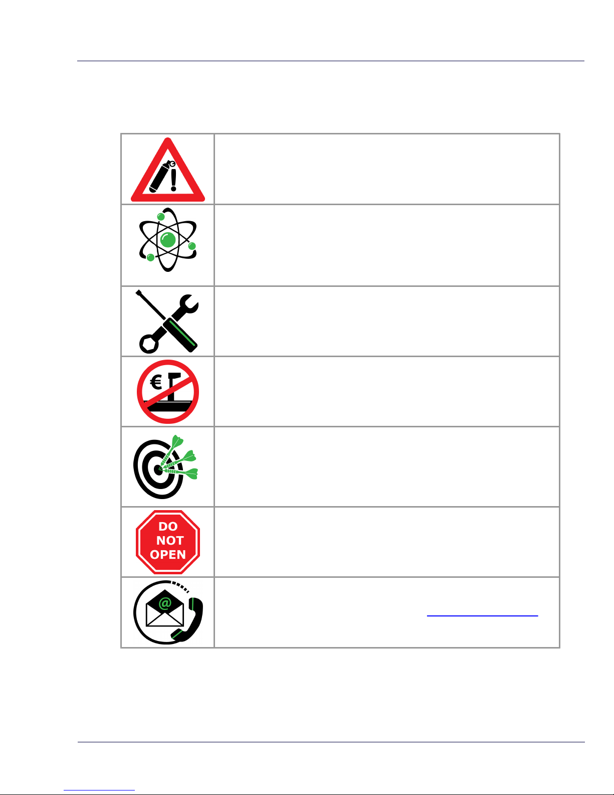
1 Warning - Read this first
Compressed air can be dangerous! Please familiarize yourself with the
forces under pressurized conditions. Respect the local guidelines and
regulations for working with pressurized equipment.
Gas flow through pipes follows certain physical laws. These physical laws
have serious consequences for the installation requirements. Familiarize
yourself with the basic physical laws of flow measurement, to make sure that
the product is installed correctly. Always make sure that upstream length,
downstream length, flow, pressure, temperature and humidity conditions are
within specifications.
Precision instruments need maintenance. Check your flow meter
regularly and make sure it remains clean. When polluted, gently clean the
sensor using de-mineralised water or cleaning alcohol.
Not intended for fiscal metering or billing. Our flow meters are not certified
for fiscal metering. Laws on fiscal metering and billing may vary per country or
state.
Do not overestimate the results. VPInstruments does not take any
responsibility for the correctness of measurement results under field
conditions. The practical measurement uncertainty of a flow meter in the field
may vary, depending on how well it is installed, due to the nature of gas flow. The
piping table provides guidelines on how to optimize the field accuracy. Our
products are not intended to be used as a single means to determine compressor
capacity.
Do not open the device. Our instruments are assembled with high precision.
Opening this device is dangerous and may destroy the instrument. Warranty is
voided when you open the instrument.
Feedback leads to product improvement. Please share your experience
with us, as we are continuously improving our products in our commitment to
quality, reliability and ease of use. Let us know via sales@vpinstruments.com!

VPFlowScope M6
© 2016 Van Putten Instruments BV | MAN-VP-MPRO-UK | Revision:1602 | Date:20-10-2016
2 Introduction
Congratulations! You purchased the easiest to use and most complete compressed air
measurement tool in the world. With the VPFlowScope M, you can monitor flow, pressure,
temperature, and total air consumption, simultaneously. The optional data logger enables you to
record all 4 parameters.
With the introduction of the VPFlowScope M, re-calibration becomes history. Unlike traditional flow
meters, the VPFlowScope M does not require traditional re-calibration. Instead, the VPFlowScope
M consists of a transmitter in combination with the patented VPSensorCartridge which reduces recalibration to a simple exchange.
But there is more to the VPFlowScope M:
Three in one: flow, pressure and temperature simultaneously
Wide measurement range (1:300)
2% reading accuracy on flow
Ultra compact size and low weight
Optional direction measurement
Optional display
Optional data logger
Great products deserve great user manuals. We have done our best to make this user manual as
complete as possible. New users, please read it carefully to familiarize yourself with our products.
Experienced users can check out the Quick start chapter.
Check the packaging box for any inconsistencies. Should there be any shipping damage, notify the
local carrier. At the same time a report should be submitted to Van Putten Instruments BV,
Buitenwatersloot 335, 2614 GS DELFT, The Netherlands.
This manual is dedicated to:
VPFlowScope M transmitter: VPM.T001.DXXX
VPFlowScope M VPSensorCartridge: VPM.R150.P35X.PN10
VPStudio software version 2.0.5
Transmitter firmware version 1.1.0
VPSensorCartridge firmware version 1.0.1
Do you like our products and this user manual? Tell others! Do you miss something? Let us know
via sales@vpinstruments.com!
Introduction 7
© 2016 Van Putten Instruments BV | MAN-VP-MPRO-UK | Revision:1602 | Date:20-10-2016
3 Product overview
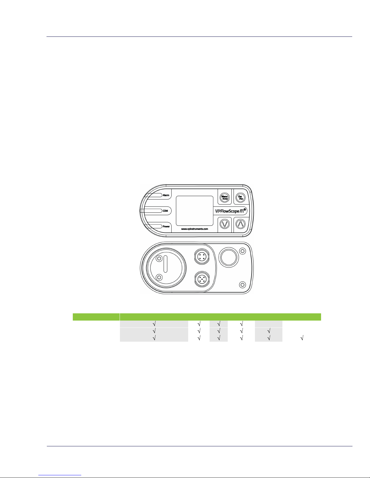
3.1 VPFlowScope M transmitter
Meet the transmitter, the 'brains' of the VPFlowScope M. The transmitter is one part of the
VPFlowScope M which needs to be combined with a VPSensorCartridge and a safety system. The
transmitter features various outputs. Modbus, 4..20 mA, pulse, USB, Ethernet, alarm are all
standard. The optional display and data logger offer additional functionality for visualisation and
data logging.
The transmitter is available in 3 configurations to fit every application. The available models are
listed in the table below. The transmitter is to be used with the VPSensorCartridge. There are two
VPSensorCartridges available, both having their own unique features. Inside the
VPSensorCartridge are sensors that perform the actual measurement.
When mated to a VPSensorCartridge, the transmitter can be rotated 360 degree. This enables you
to align the display for every orientation. Turn the locking ring loose when rotating the display.
Available transmitter models
Order Code
4..20 mA/ Pulse/ Alarm
RS485
USB
Ethernet
Display
Data logger
VPM.T001.D000
VPM.T001.D010
VPM.T001.D011
Available models on day of printing
VPFlowScope M8
© 2016 Van Putten Instruments BV | MAN-VP-MPRO-UK | Revision:1602 | Date:20-10-2016
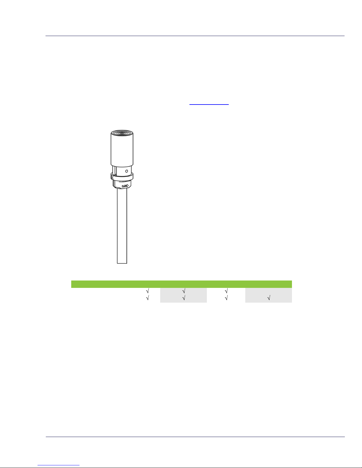
3.2 VPSensorCartridge
The VPSensorCartridge includes all sensors to measure flow, pressure and temperature
simultaneously. It also includes the calibration characteristics for all available sensors. This makes
it possible to exchange the VPSensorCartridge between transmitters or to replace it when
calibration is required.
All VPSensorCartridges use a proprietary interface. Therefore every type of VPSensorCartridge
can be connected to every model of transmitter. See chapter 3.1 for all available transmitters.
The VPSensorCartridge has a flow direction indicator in the shape of an arrow that points in the
positive direction. The indicator can be used for proper alignment.
Available VPSensorCartridge models
Order Code
Flow
Temperature
Pressure
Bi-directional
VPM.R150.P350.PN10
VPM.R150.P351.PN10
Available models on day of printing
Product overview 9
© 2016 Van Putten Instruments BV | MAN-VP-MPRO-UK | Revision:1602 | Date:20-10-2016
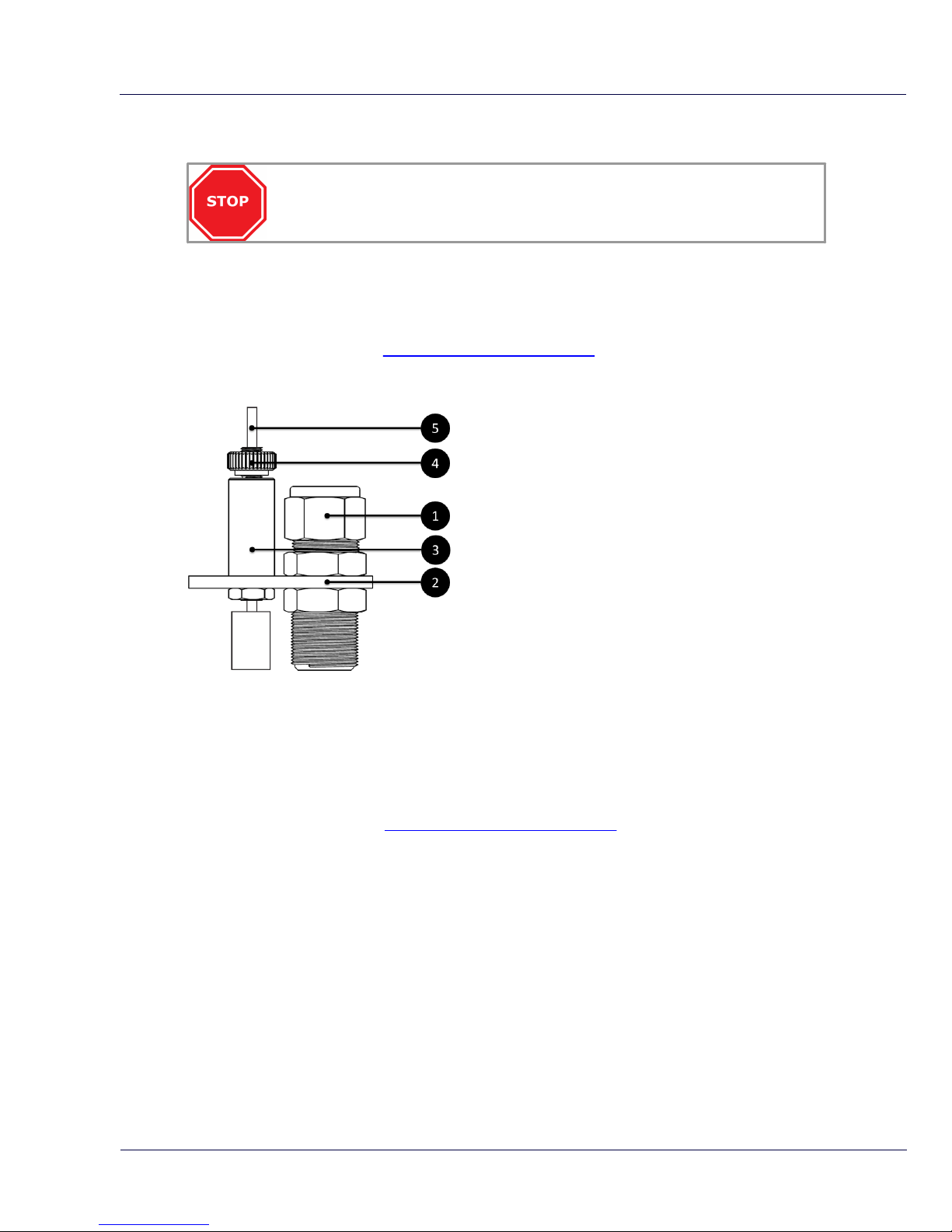
3.3 Safety system
Installation under pressure can be dangerous. Make sure that you understand the
safety system before installing the VPFlowScope M.
The safety system is specially designed for the VPFlowScope M. When the VPSensorCartridge is
in the compression fitting and the safety cable is attached with the locking ring fully tightened, the
probe can never exit the compression fitting due to the matching length of the cable. When the
VPSensorCartridge is installed on the right depth, the safety cable can be strained and locked. The
complete safety system is tested and certified for safety. Instructions on how to assemble the
safety system can be found in chapter 6 mechanical installation.
1. Compression fitting: 0.5 inch with Teflon ferrule
2. Safety plate: Used to connect fitting and safety
system
3. Auto brake: The safety chain can be slide through
the auto brake system. Moving upwards is only
possible when the safety lock is pushed downwards
4. Safety lock: This nut can be used to lock or unlock
the safety release. Push down the lock to release
the safety chain
5. Safety chain: The safety chain can be attached to
the VPSensorCartridge
3.4 Configuration
The VPFlowScope M needs only one step to be ready for basic operation. It needs to know the
exact inner pipe diameter for accurate measurement, wrong inner diameter will lead to very
significant misreadings. The pipe diameter can be programmed with the keypad on the display
module, via the built-in Web interface or with the VPStudio configuration software. This software
suite is also used for configuration of the outputs and data logger. This software can be
downloaded from our website. www.vpinstruments.com/downloads. The exact inner diameter can
be measured using a wall thickness gauge, ask us for availability.
The default units are set to SI. For read out in Imperial units, use the keypad to change the units via
the menu. Go to menu->settings->display->rows.

VPFlowScope M10
© 2016 Van Putten Instruments BV | MAN-VP-MPRO-UK | Revision:1602 | Date:20-10-2016
4 Quick start
This chapter contains the basic steps to start using your VPFlowScope M. Additional information on
all subjects can be found in the next chapters.
1. Unpack
Unpack the box and check if all items are there and in good shape.
2. Apply power
Connect the unit to a DC power source (12..24 VDC). See chapter 7 electrical connections.
3. Mechanical installation
Find the best point of installation for this product. Make sure that the process conditions are
within the specifications of the flow meter and the upstream and downstream straight pipe
lengths are respected
For installation of the VPFlowScope M, an insertion point needs to be created. A socket with
internal 1/2 inch thread is required
A ball valve with a minimum size of 0,5 inch female BSP or NPT process connection should be in
place
Assemble the VPFlowScope M including safety system and mount it on top of the ball valve
Open the valve and insert the probe
The sensor needs to be in the middle of the pipe for diameters larger then 2 inch. See chapter
6.1 installation point
Tighten the compression fitting according to instruction
Pull on the safety chain to strain it and turn the safety lock clockwise to lock it
See chapter 6 mechanical installation for more detailed information
4. Electrical installation
4.1 Permanent installation
Connect a cable with 5 Pin M12 connector to the transmitter. The cable can be connected to
VPVision, a central data acquisition / building management system or data logger via Modbus
RTU (TCP), 4..20mA or pulse. Connect the 4 Pin M12 connector to the transmitter and the
other side to a laptop or router for an Ethernet connection.
Apply 12..24 VDC to power up the device. Use a Class II power supply (less than 2 Amps). If a
display is present, it will light up when power is applied.
4.2 Temporary installation
Use a 24 VDC power supply with M12 connector to power the device.
See chapter 10 electrical connections for more information.
5. Configure the transmitter
For correct measurement, the diameter should be programmed into the instrument.
The quickest way: Program the inner pipe diameter via the display. Go to menu->settings>diameter
Alternative method: The diameter can also be programmed through an Ethernet connection
using the internal web server and direct USB connection to the transmitter using the VPStudio
software
Advanced settings: Use the built in web server or VPStudio to set the output parameters for
networking, Modbus, pulse, alarm and current outputs
6. Data recording
When the transmitter has an integrated data logger, a data log session can be started pressing the
record button. The data logger uses 5 second intervals for all measurement parameters by default.
The data logger can also be put in cyclic mode where it will always record data using 1 second
intervals for all parameters. Changing the mode and intervals can be done using the display or with
the VPStudio software.
Quick start 11
© 2016 Van Putten Instruments BV | MAN-VP-MPRO-UK | Revision:1602 | Date:20-10-2016
5 Measurement
For all parameters the update interval is 1 second. Within this second, multiple samples are taken
and averaged to provide a stable and reliable output.
5.1 Flow
The VPSensorCartridge uses our proprietary insertion type thermal mass flow sensor. There is no
bypass flow, which results in a high robustness and less sensitivity for dirt or particles. The flow
sensor is directly temperature compensated. The flow reading is under normalized conditions (DIN
1343).
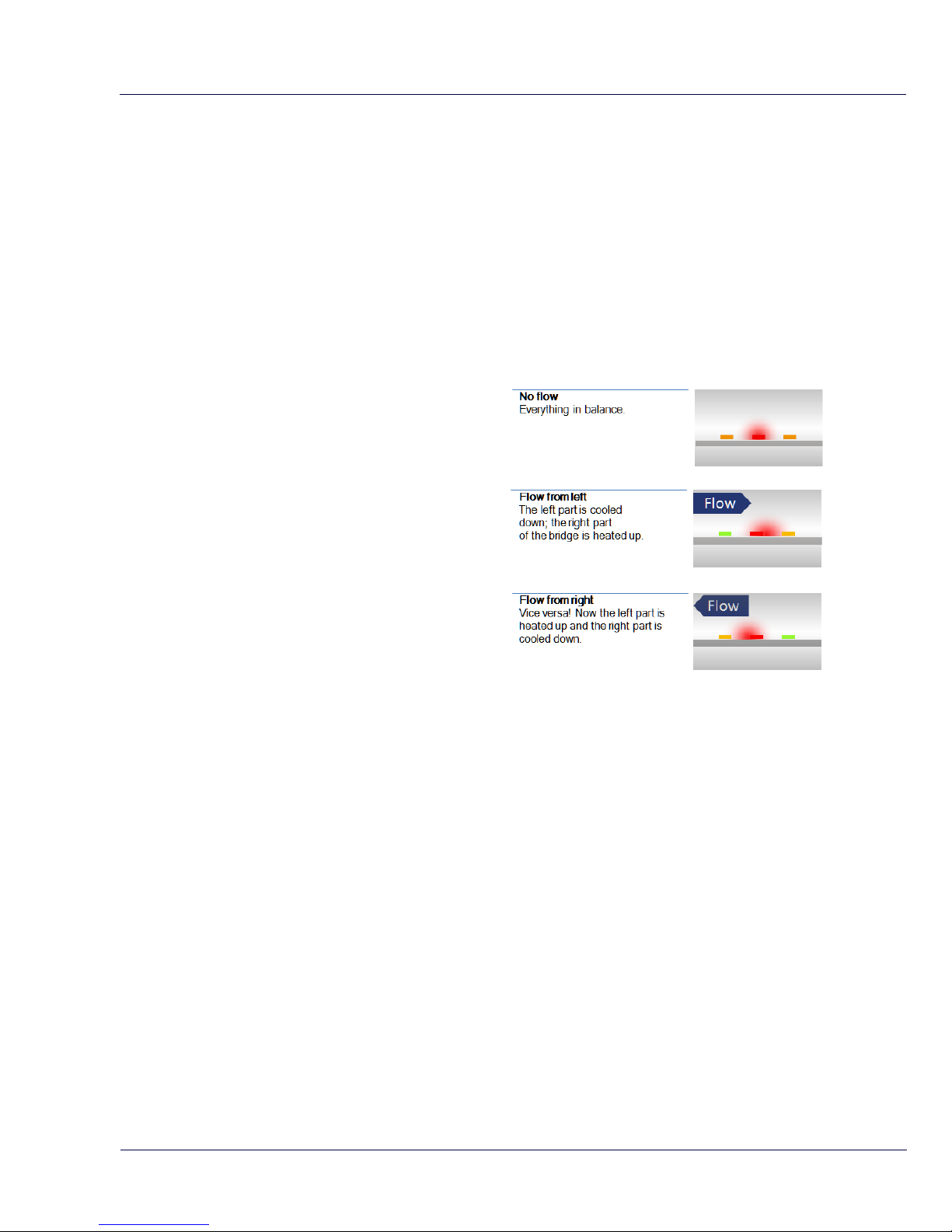
The sensor response signal is directly related to
the mass flow rate and can be described by the
following formula:
Vout = k *λ* ρ * v * (Ts-Tg)
Vout = output voltage
k = sensor (geometrical) constant
λ = thermal conductivity of the gas
ρ = density of the gas
v = actual velocity in m / sec
Ts = sensor temperature
Tg = gas temperature
The optional bi-directional sensitivity is shown in
the picture on the right. In bi-directional mode
the negative flow value will show up as a minus
sign.
5.2 Pressure
The VPSensorCartridge features a built-in gauge pressure sensor. Check specifications for details.
The sensor membrane can handle media which are compatible with glass, silicon, stainless steel,
Sn/Ni, plating and An/Ag solder.
5.3 Temperature
The built in temperature sensor measures the compressed air / gas temperature.
At low flow rates between zero flow and 10 mn/sec, the temperature sensor may heat up itself due
to the heated flow sensor element. This will result in higher read out for temperature.
Temperature compensation effects: The flow sensor is compensated dynamically for changes in
gas temperature. When exposed to quick temperature changes or large temperature changes (for
example taking the unit from outdoor to indoor during winter time, or when mounted downstream of
a heat regenerated drier) the temperature compensation may lag behind, which may result in
significant measurement errors.
5.4 Totalizer
The totalizer keeps track of the total consumed amount of compressed air in normal cubic meters,
normal liters per minute or in (M)(M)SCF depending on which unit you choose to read out. The
refresh interval is 1 second: Actual totalizer data will be available on the display and via the Modbus
interface. The totalizer value is written to it's internal memory with an interval of 15 minutes. A

VPFlowScope M12
© 2016 Van Putten Instruments BV | MAN-VP-MPRO-UK | Revision:1602 | Date:20-10-2016
power failure may result in maximum 15 minutes of totalizer data loss.
The transmitter features 2 totalizers, plus a combined totalizer. The first totalizer counter will count
up all positive flow, the second counter will count up all negative flow. The sum of these two
totalizer values is shown on the display and can also be read out via Modbus. The display will show
totalizer values up to 99.999.999,9 and will then become 0,0 independent of the taken unit. The
totalizer will not be cleared and higher values will be available via Modbus and VPStudio. Via
Modbus, all three totalizers are available. See chapter 9 for Modbus registers.
The totalizers can only be reset to zero, and will be reset all together. It's not possible to set them to
any different value.
Measurement 13
© 2016 Van Putten Instruments BV | MAN-VP-MPRO-UK | Revision:1602 | Date:20-10-2016
6 Mechanical installation
6.1 Installation point
The installation point is crucial for a correct measurement. Sources of error can be: installation
effects, unknown flow profiles, swirls, pressure and temperature effects, humidity effects,
oscillations in the flow, etc. To ensure the highest possible accuracy of flow measurement, the
installation and piping instructions must be followed. Therefore read this paragraph carefully.
Take into account:
Choose a location which is accessible, which allows access for wiring and maintenance activities
Meet the specifications of the VPFlowScope M. When the specifications are not met, for instance
the pressure or temperature level is too high; this will cause inaccurate flow measurement and
can even damage your flow meter
Do not apply mechanical stress on the VPFlowScope M
Avoid:
Excessive heat, check the temperature specifications
Corrosive atmosphere where possible
Electrical problems (high voltage/ high power)
Mechanical vibration and danger (walking bridges, fork lift trucks)
Any environmental source of potential error
Stop: These devices are for use with Air, Nitrogen, Argon, Helium, Carbon Dioxide
and other non hazardous and non-corrosive gases
Prepare the installation
The VPFlowScope M can be inserted through a tap with 1/2 inch female thread. For installation
under pressurized conditions a VPInstruments hot tap saddle can be used.
Use a 1/2" full bore ball valve to insert and retract the VPFlowScope M when you want.
Warning: Make sure that the hole is at least 16 mm | 0.63 inch, and completely clear
for insertion. A too small hole will damage the probe or can block the probe when the
entering the pipe.
VPFlowScope M14
© 2016 Van Putten Instruments BV | MAN-VP-MPRO-UK | Revision:1602 | Date:20-10-2016
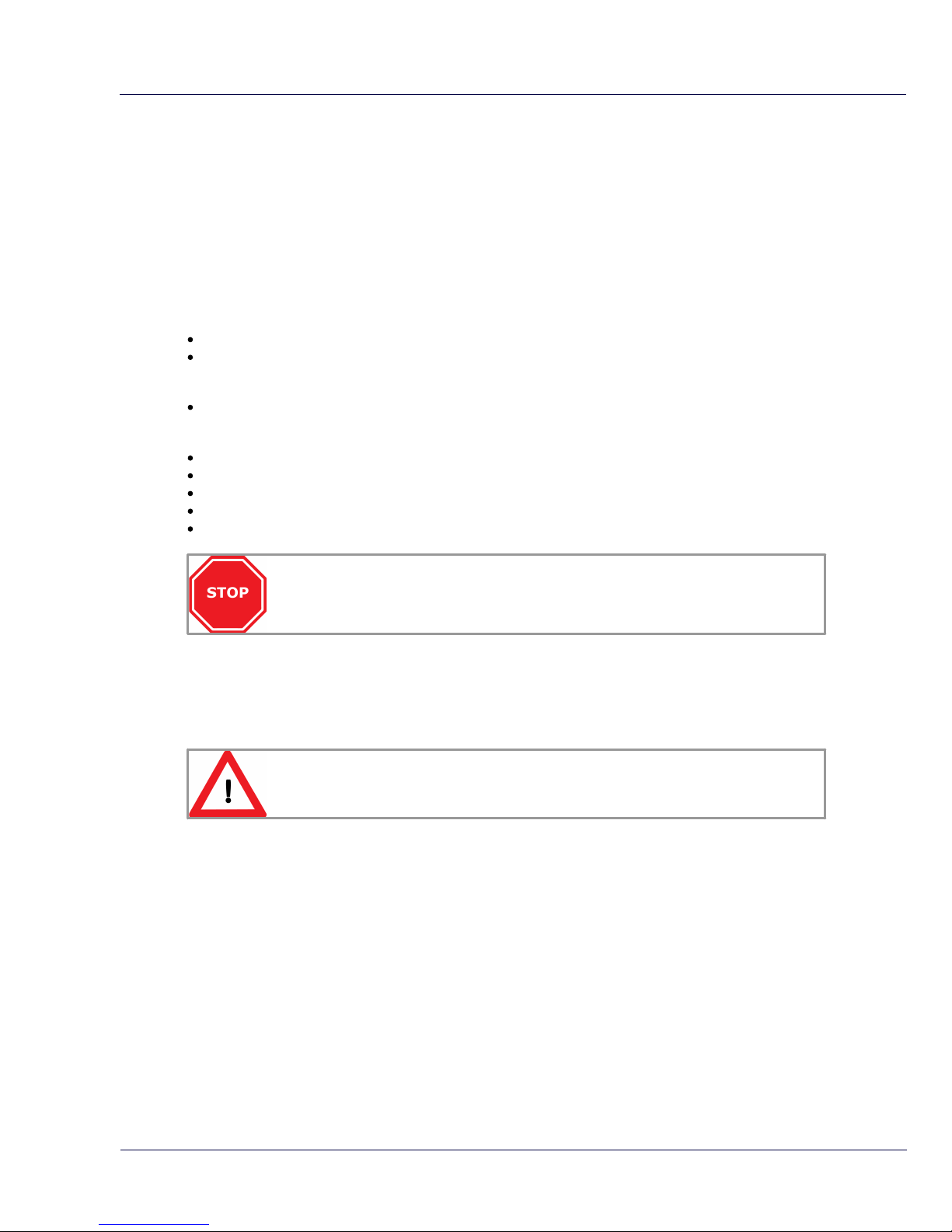
Installation procedure
Insertion depth
Generally the insertion depth of the VPFlowScope M is 0.5 times the
inner pipe diameter, where the bottom of the sensor tip must be in
the middle of the pipe (see picture).
Position
Install the VPFlowScope M upwards in an angle between 1 and 2
o'clock (see picture). Never install the instruments upside down.
The VPSensorCartridge has a flow direction indicator, this also indicates the alignment of the
instrument. A second indicator can be found on the safety system. Make sure it points in the right
flow direction. Alignment “by the eye” is sufficient.
Info: A ruler can be used to align the instrument. It can be placed on the flat area
where the direction indicator is located.
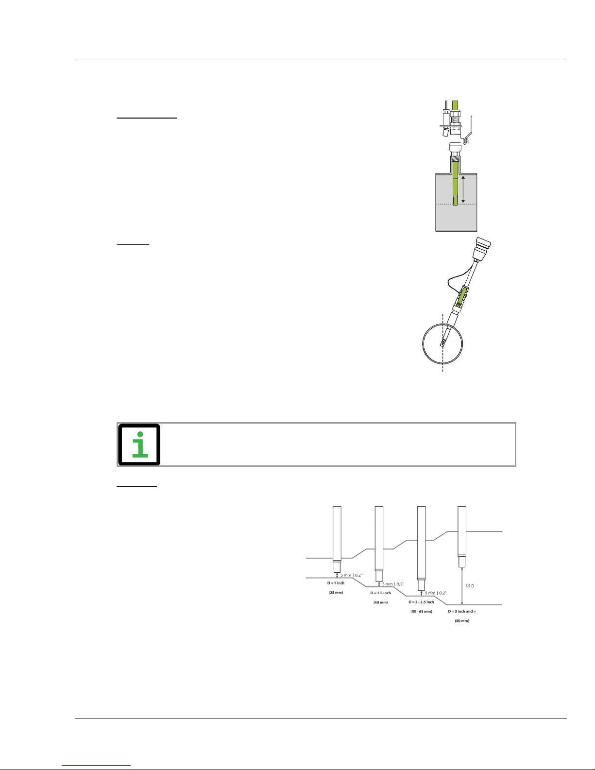
Exception
Between pipe sizes of 1” and 2”: be aware
that the field accuracy is +/- 10%;
installation errors are bigger. The insertion
depth between DN25 and DN65 is also
different. The VPFlowScope M probe has to
be inserted almost completely to the bottom
of the pipe or else the temperature sensor
of the VPFlowScope M probe itself is
outside the flow path. The sensor tip will not
be in the middle of the pipe any more. The
measurement value is automatically
corrected for small diameters.
Mechanical installation 15
© 2016 Van Putten Instruments BV | MAN-VP-MPRO-UK | Revision:1602 | Date:20-10-2016
6.2 Piping table
Check the piping table below for your application. The table shows the amount of length upstream
or downstream depending on the installation. If applicable in front of the meter, use given upstream
length. If applicable in behind the meter, use given downstream length. Gas flow in pipes follows
certain rules, which must be observed for optimal measurement results. For some exceptions the
upstream length needs to be longer, or can be shorter.
If possible, you can always choose a longer upstream length, as these are minimum
values. The up- and downstream lengths are used industry wide as guidelines, but
will never be a guarantee for obtaining the “true value”.
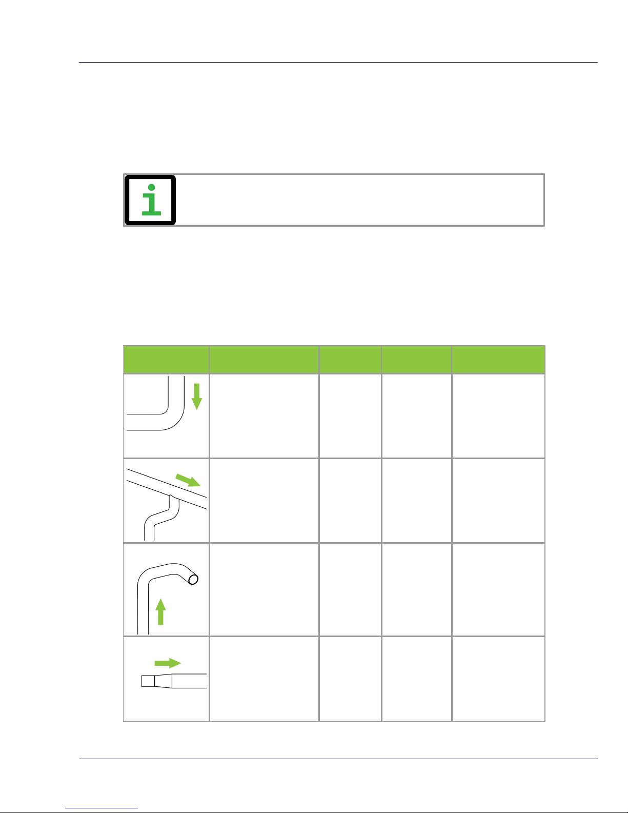
Piping table
The following table provides a guideline for proper distances between upstream or downstream
objects and the VPFlowScope M. The upstream length is the length between the last non-straight
object and the VPFlowScope M. If the upstream length is straight, and the distortion is downstream
of the VPFlowScope M, you can use the column "downstream length" as a guideline. In very
complex situations, with multiple up- and downstream objects, you should consider another
location. This table is a practical guideline and is not exact science. Practical situations can have
multiple sources of distortion, therefore VPInstruments does not take any responsibility for the
correctness.
Picture
Description
Upstream
length
2
Downstream
length
2
Effect
Single elbow
30 * D
1
10 * D
1
Distorted flow profile
Complex feed-in
situation (header)
40 * D
1
10 * D
1
Flow profile will be
distorted
Double elbow, multiple
elbows following each
other
40 * D
1
10 * D
1
Distorted profile +
swirl
Diameter change from
small to large (gradual
or instant)
40 * D15 *D
1
Jet shaped flow
 Loading...