

Page 1

User Manual
Page 2

Contents
Page
General Information
Intended Use 3
Safety Information 4
Overview of parts 5
Specifications 6
Operation
Unfolding the walker 8 & 9
Attaching Arm Supports 10
Folding the Walker 11 & 12
Basic Components & Adjustments
Seat Lifting Force & Height 14 to 20
Forearm Support 21 to 23
Front Wheels Swivel 25 to 27
Walker Frame (width) 31 to 39
Walker Frame (height) 40 to 51
2
Page 3

Intended Use
• The FROG walker provides support during gait training and is to be used as part of
a developmental program.
• An initial training phase with a therapist is recommended to orient the child with
the walker.
• After sufficient training, the child should be able to use the walker autonomously
to transition from walking/standing to sitting and vice versa.
3
Page 4

Safety Information
• Walker should be used on fairly flat ground.
• User should remain within the boundaries of the frame during use.
• Before use, check that all knobs & pins on frame, armrest, seat and
wheels are tightened.
4
Page 5
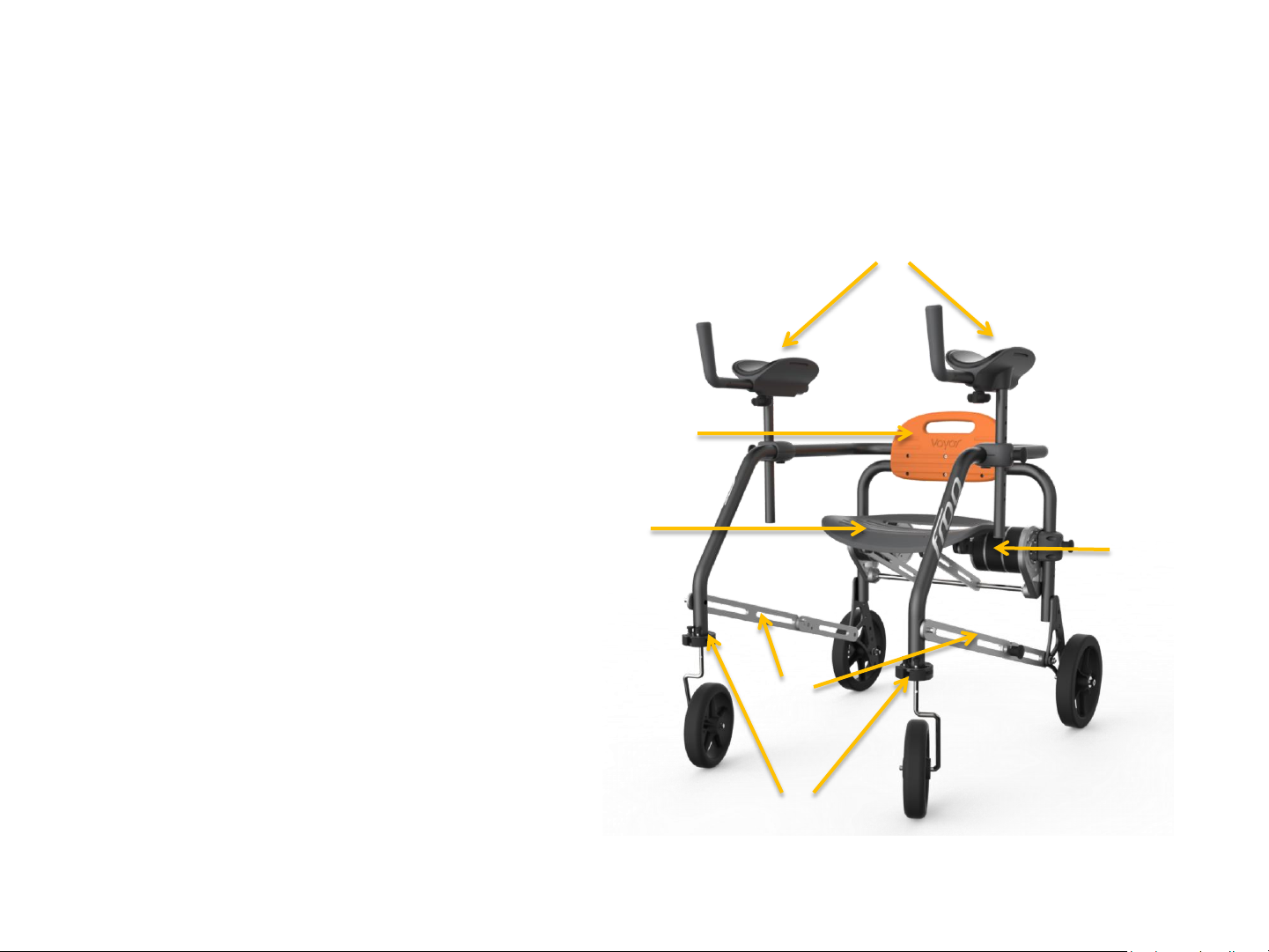
Overview of parts
A. Adjustable forearm supports
B. Backrest
C. Adjustable lift seat
D. Seat mechanism
A
E. Foldable frame
F. Adjustable wheel casters
B
C
D
E
F
5
Page 6
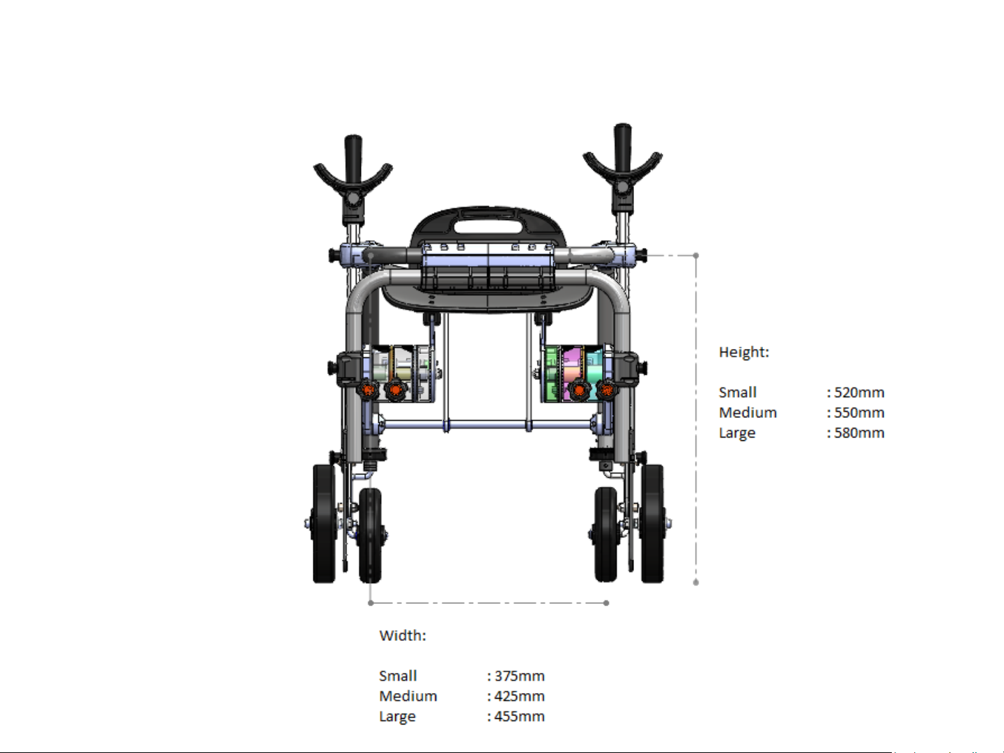
Specifications
6
Page 7

Unfolding & Folding of the walker
7
Page 8
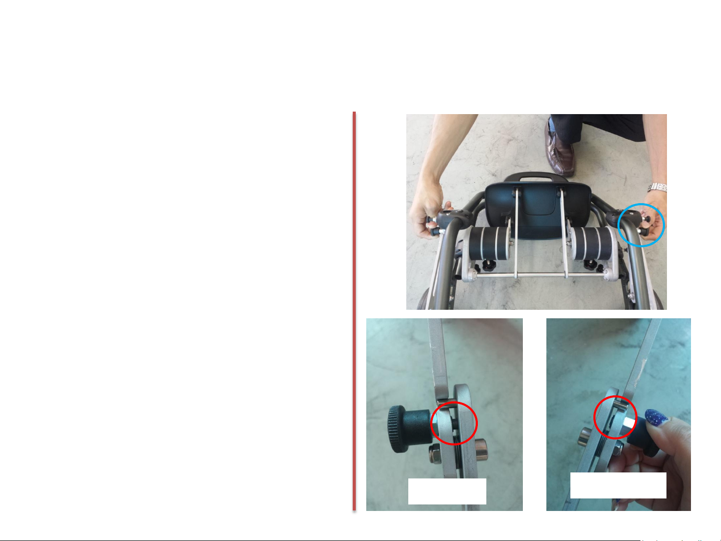
Unfolding the Walker
Releasing the plunger locks:
1. Pull out and dis-engage left lock on frame.
R
L
Engaged
Dis-engaged
8
Page 9
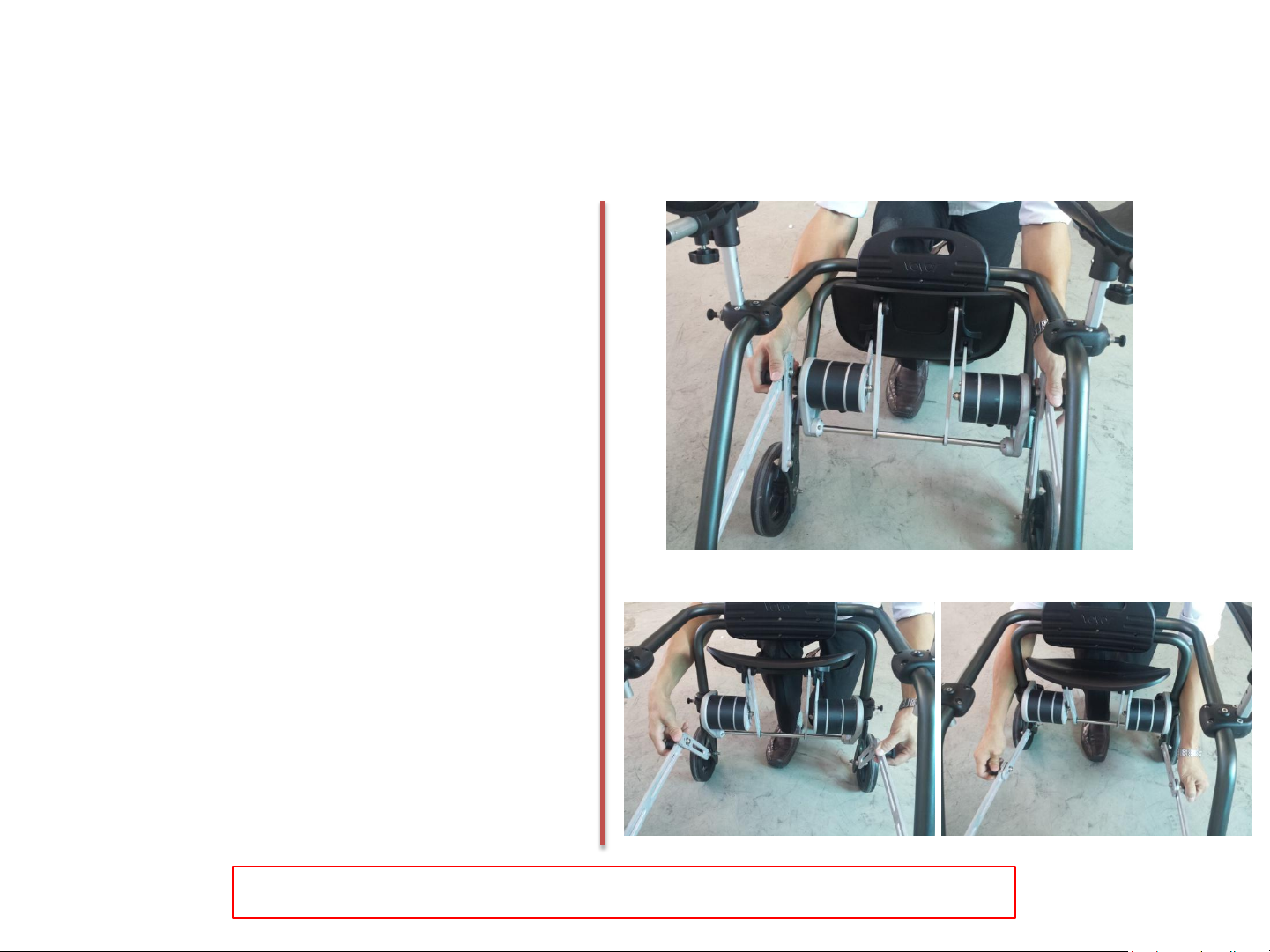
Unfolding the Walker
Unfolding the walker:
1. Holding on to the left lock and frame,
slowly lift walker in an upward and
forward motion. The frame will
straighten out to unfold the walker.
2. Once walker is upright, ensure locks on
both sides are back into ‘engaged’
positions.
Caution: Please ensure locks are fully engaged before use.
9
Page 10

Attaching Arm Supports
1. Locate the armrest socket.
2. Pull out lock [3] and hold it in
position.
3. Holding the aluminium shaft, lower the arm
support into the hole.
4. Release lock back in, ensuring pin
inside has engaged with the hole on
the shaft. If not, gently slide
the shaft up or down until lock engages.
Refer to 'Basic Components' section for how to adjust
arm supports.
10
Page 11
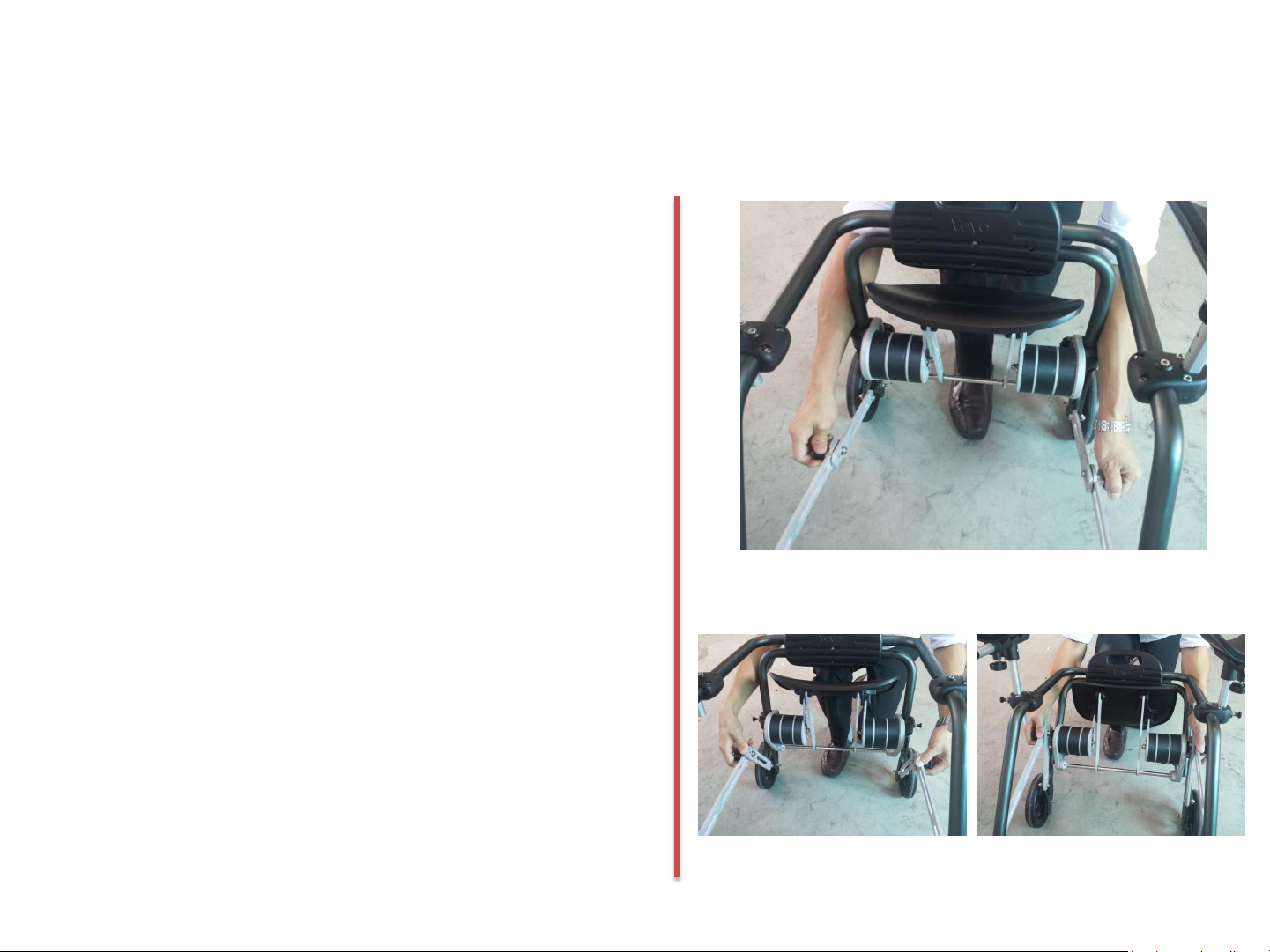
Folding the Walker
1. Remove both armrests from their sockets.
2. Supporting the weight of the walker via the
rear end, pull out and dis-engage lock on each
side of frame.
3. Holding on to both sides of lock and
frame, slowly lift walker in an upward and
backward motion, and subsequently
downwards to let frame fold into position.
11
Page 12
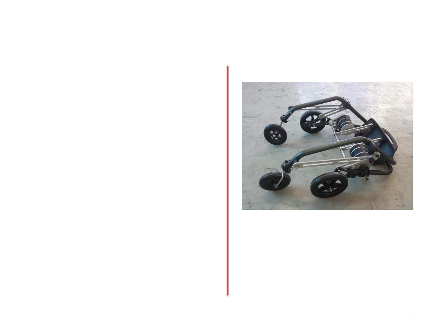
Folding the Walker
4. Push pins on both sides back into
‘engaged’ position.
5. The walker is now secured and folded.
12
Page 13

Basic Components:
Seat & Forearm support adjustments
13
Page 14
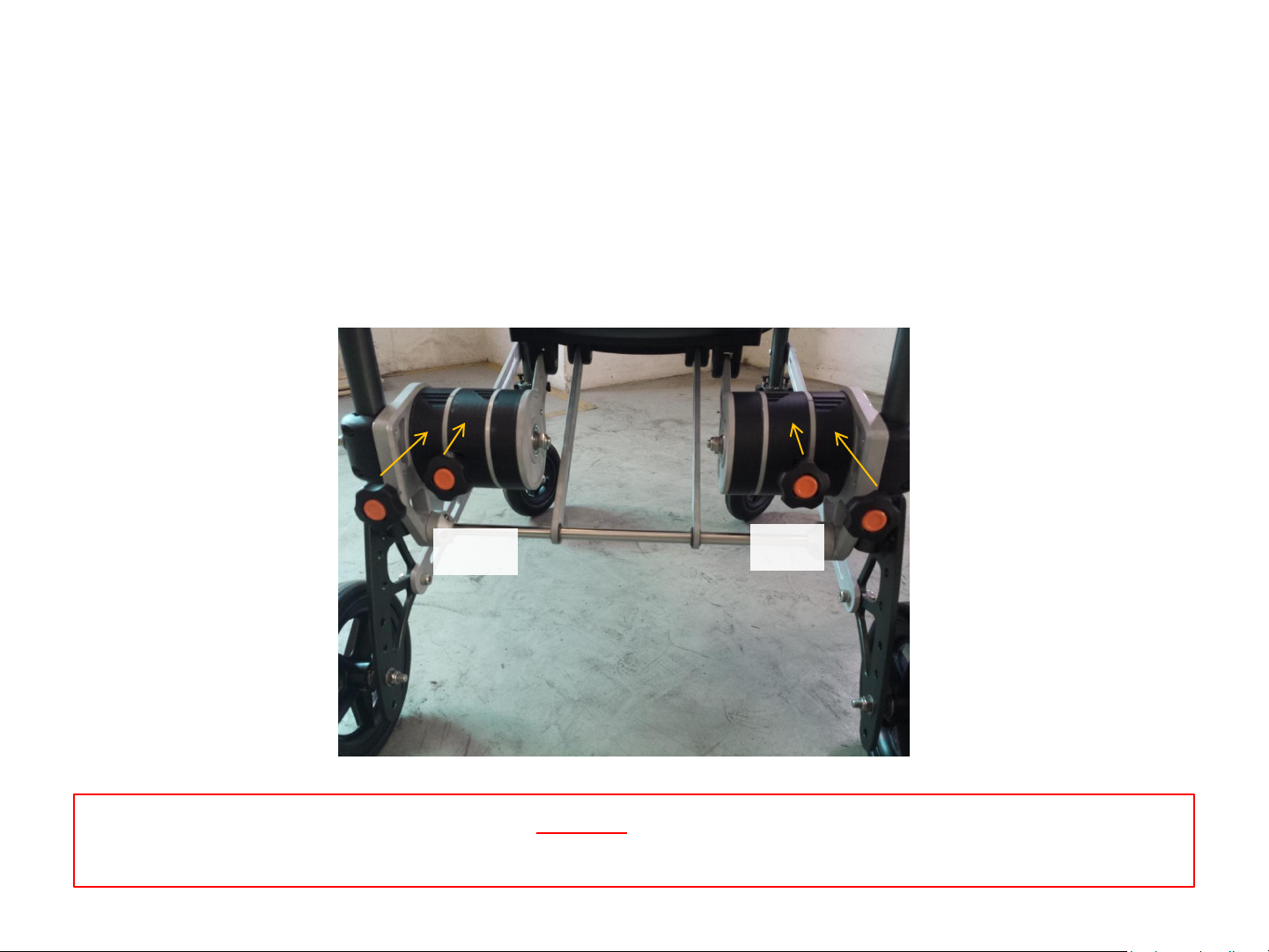
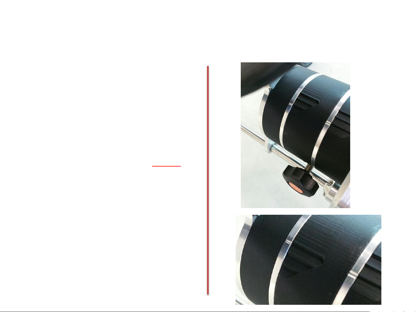
Seat Lifting Force
Lift force is controlled by mechanisms located on both the left and right of the walker.
There are two components for each side - [A] and [B].
A B
Right
Important: [A] should be adjusted equally on BOTH sides before use. Similarly for [B].
Adjustments should also only be done when child is NOT seated.
A B
Left
14
Page 15
[B]
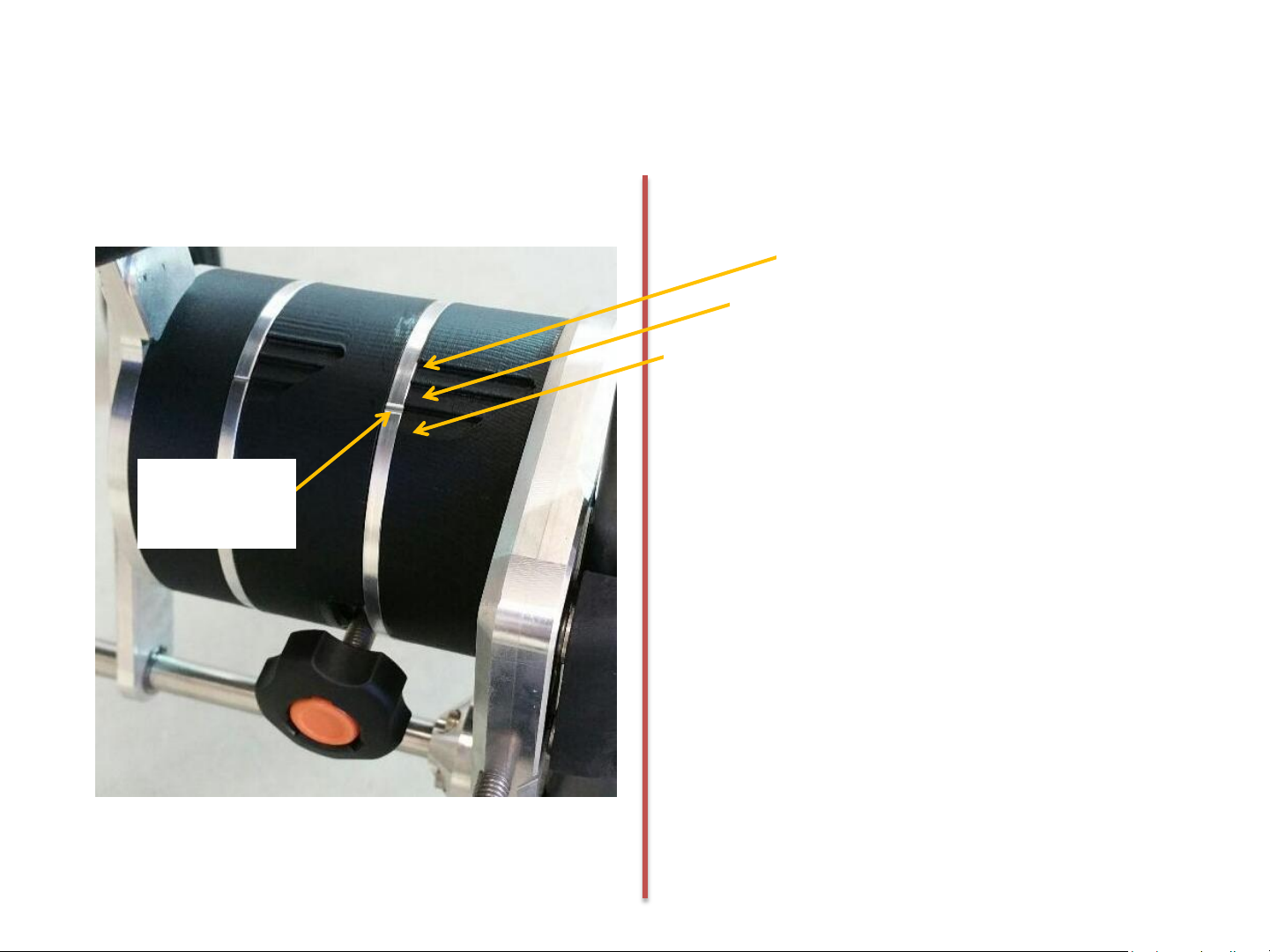
Seat Lifting Force
High Force
[A]
Medium Force
Low Force
Line Mark
On Disc
[A] controls the amount of lifting force the
child feels when sitting down. The higher the
force, the easier it will be for the child to get up.
[B] controls how smooth the transition is from
the first contact with the seat until [A] is
engaged. Decreasing [B] means it will be easier
for the child to sit down.
15
Page 16

Seat Lifting Force
Starting from the left drum, turn Knob [A]
to adjust desired Spring Force either to Low
(1), Medium (2) or High (3).
Repeat the same to the drum on the right.
Spring force should be adjusted equally on
BOTH drum sides before use.
Adjustments should also only be done
when child is NOT seated.
Low
Force
[A]
High
Force
1
2
[A]
3
1
2
3
16
Page 17
Seat Lifting Force
Starting from the left drum, turn Knob [B]
to adjust desired Spring Force either to Low
(1), Medium (2) or High (3).
Repeat the same to the drum on the right.
Spring force should be adjusted equally on
BOTH sides, and typically equally between
A & B, before use.
Adjustments should also only be done
when child is NOT seated.
Low
Force
High
Force
1
2
[B]
3
1
3
2
17
Page 18
Seat Height
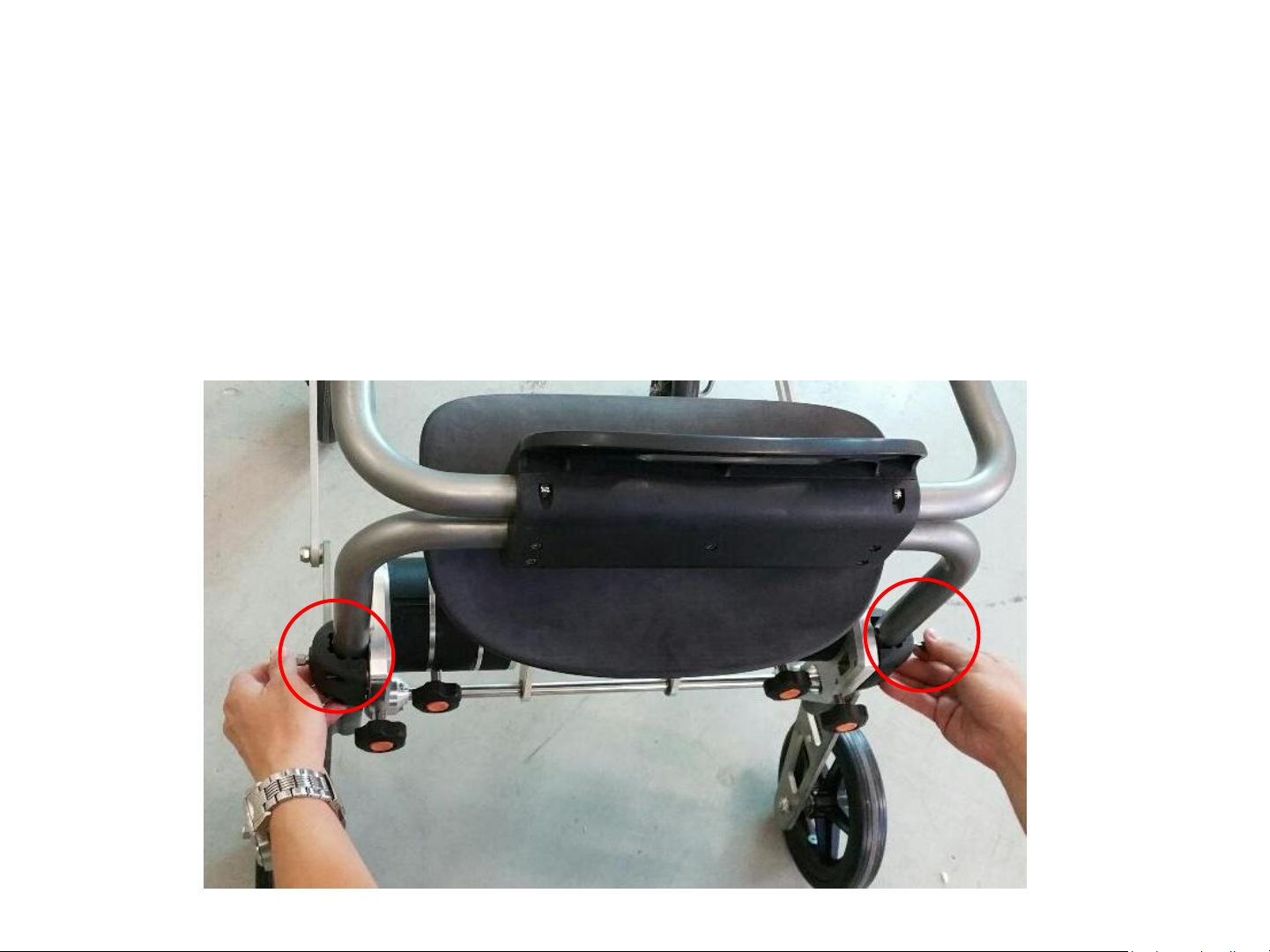
To adjust the Seat Height:
1. Pull the locks out and hold, on both sides (Left and Right).
2. Slide the whole seat assembly up or down.
3. Release the locks back in the hole on both sides.
18
Page 19
Seat Height
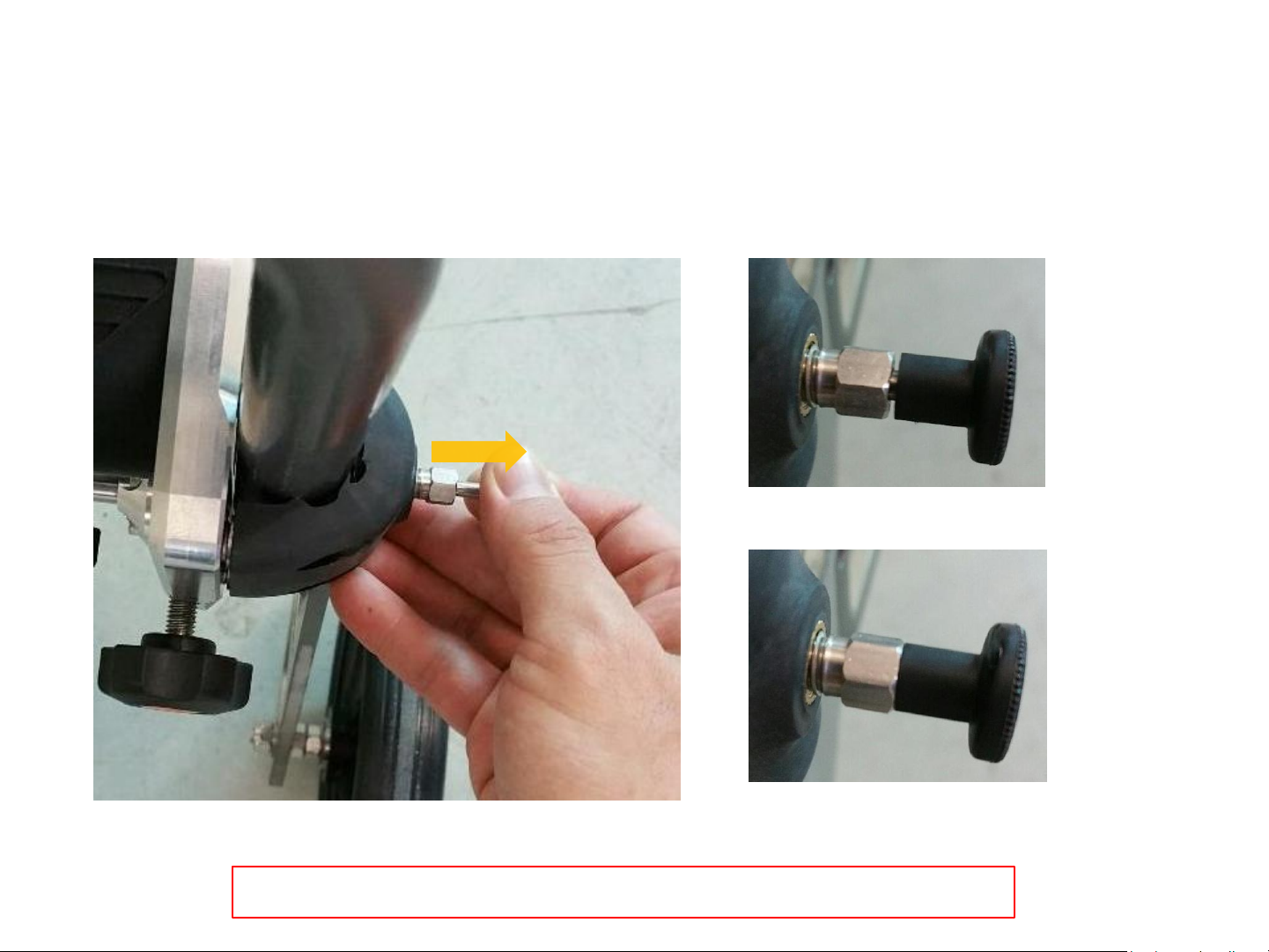
Pull the locks out on both sides (Left and Right).
Lock is not fully engaged into the hole.
Lock is fully engaged into the hole.
Caution: Please ensure pins are fully engaged before use.
19
Page 20
Seat Height
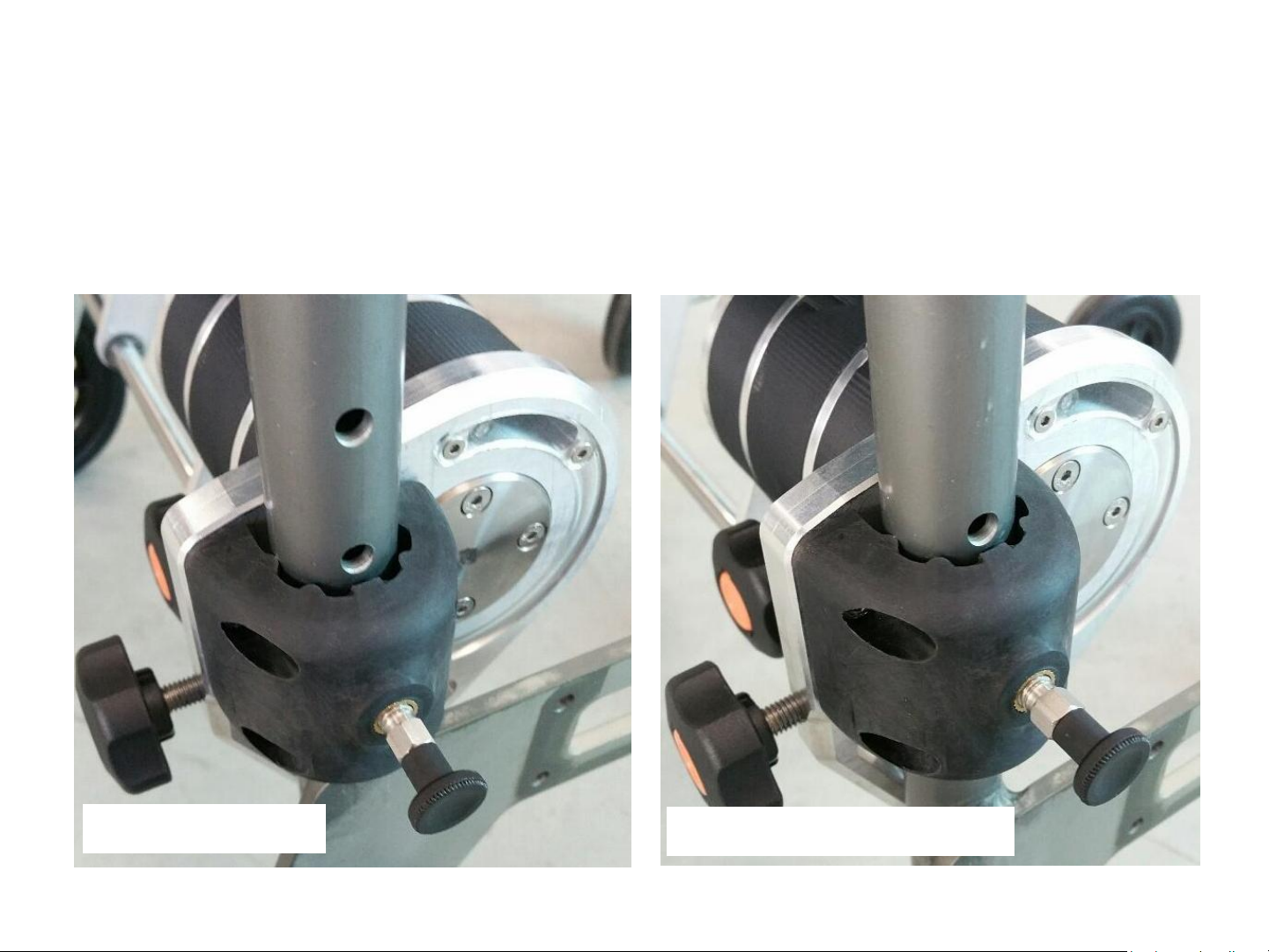
Sliding the black plastic Slider part up or down.
Low Seat Height
Intermediate Seat Height
20
Page 21
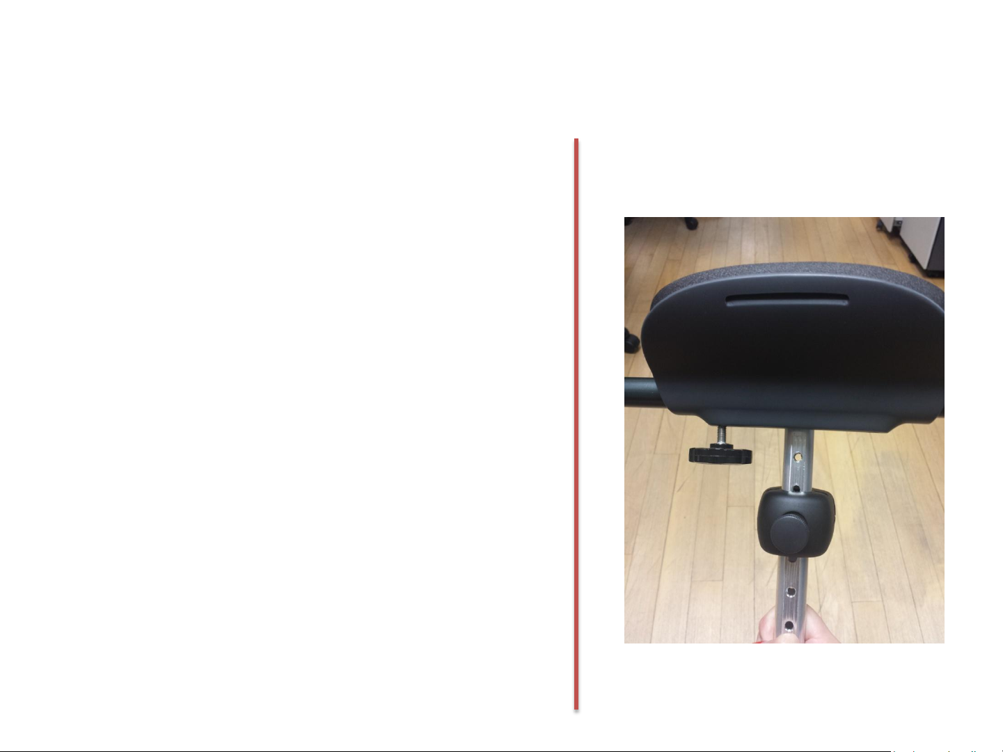
Forearm Support
3 knobs are used to adjust the forearm supports:
• Knob [1] controls the angle and length/extension
of the handhold.
• Lock [2] controls the height of the whole forearm
support.
[1]
[2]
21
Page 22
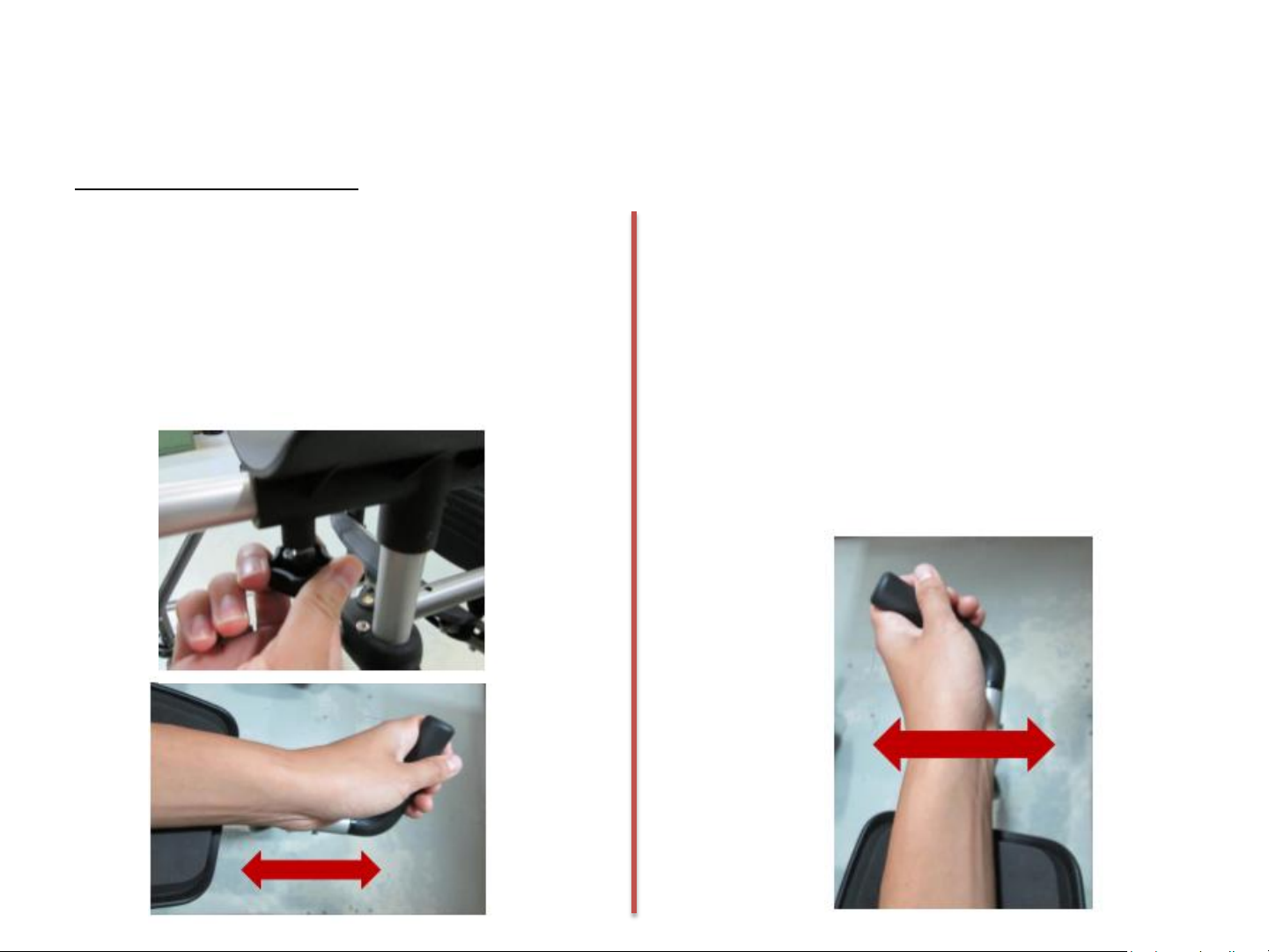
Handhold Adjustment
Forearm Support
To adjust length:
1. Loosen knob [1].
2. Slide handhold forward or backward
to desired distance.
[1]
To adjust angle:
With knob [2] still loosened,
1. Rotate handhold left and right to
desired angle.
2. Tighten knob [1]. Repeat with the
other side.
22
Page 23
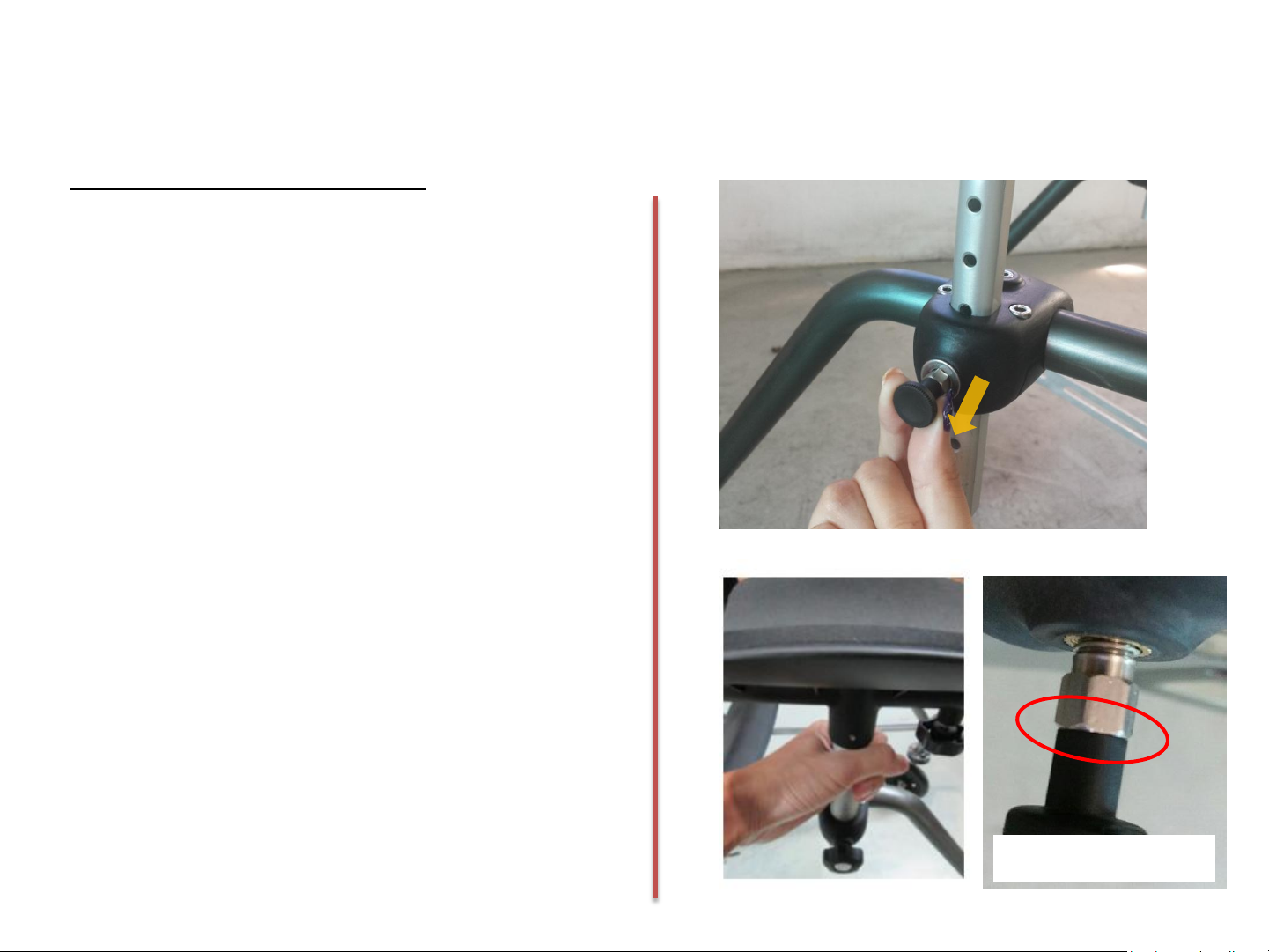
Forearm Support
Forearm height Adjustment
To adjust height:
1. Pull out lock [2] and hold it in
position.
2. Slide post up or down to desired
height.
3. Release lock back in, ensuring pin
inside has engaged with the hole on
the shaft. If not, gently slide
the shaft up or down until pin engages.
[2]
Fully engaged pin
23
Page 24

Basic Components:
Front-Wheels swivel adjustments
24
Page 25
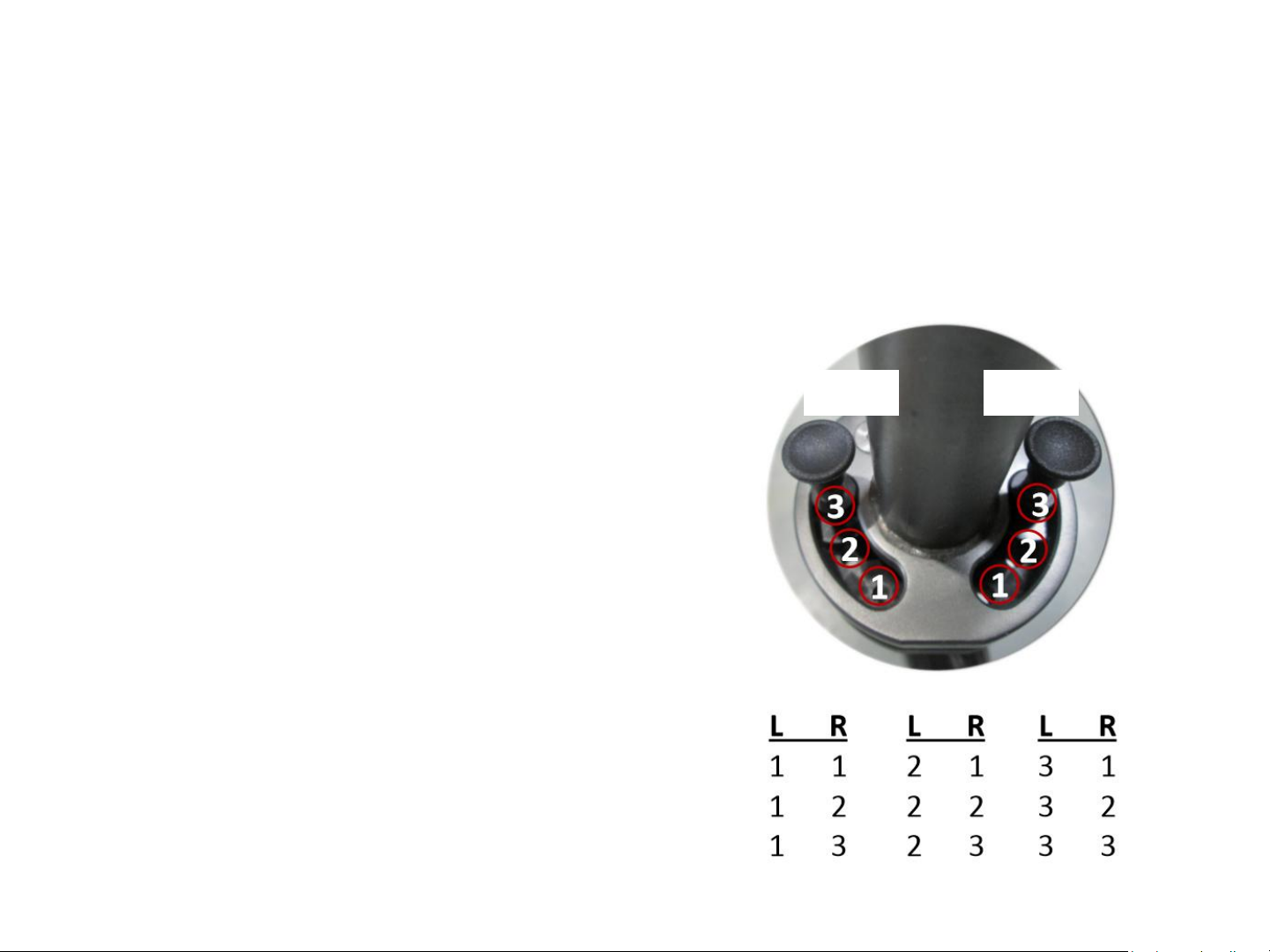
Front Wheel Swivel
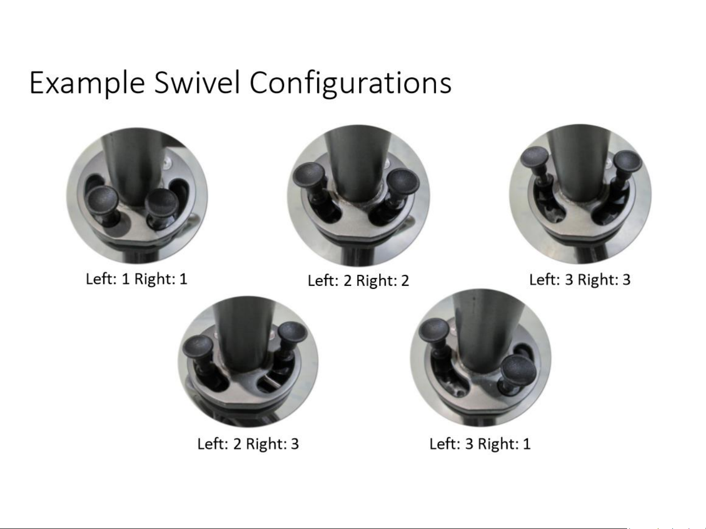
Swivel limits can be independently adjusted for each individual wheel, and each side
of the wheel (lock 1 & 2).
• Position 1: 0° Swivel
• Position 2: 30°Swivel
• Position 3: 60°Swivel
Lock 1 Lock 2
25
Page 26
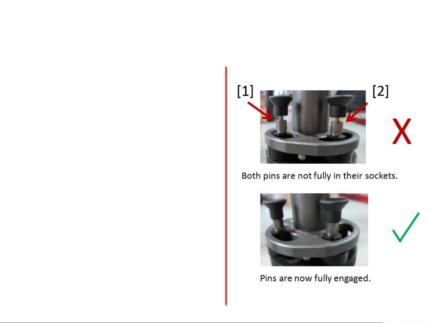
Swivel Limits
To adjust limits:
1. Pull up on lock [1].
2. Move pin to desired position (1, 2, 3).
3. Release lock 1.
Note: If you don't hear a click, the pin is not
fully engaged. Simply jiggle the pin until you
hear a small click.
4. Repeat with pin [2].
5. Repeat with other wheel.
26
Page 27
27
Page 28

Basic Components:
Walker frame adjustments
28
Page 29
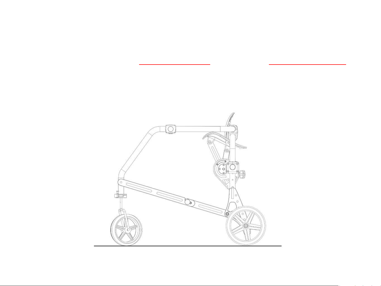
Adjustment of walker frame size
Note: Please ensure walker is unfolded & upright, and placed on even ground/surface
before adjusting width & height of walker.
29
Page 30
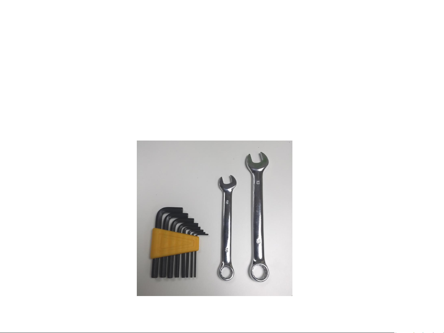
Adjustment of walker frame size
A set of Allen keys and 2 spanners is provided with the shipment.
Different sizes of Allen key and spanner are required, which arespecified with each step
(Allen Keys no. 2.5, 3 & 4 / Spanners no. 10 & 13)
30
Page 31
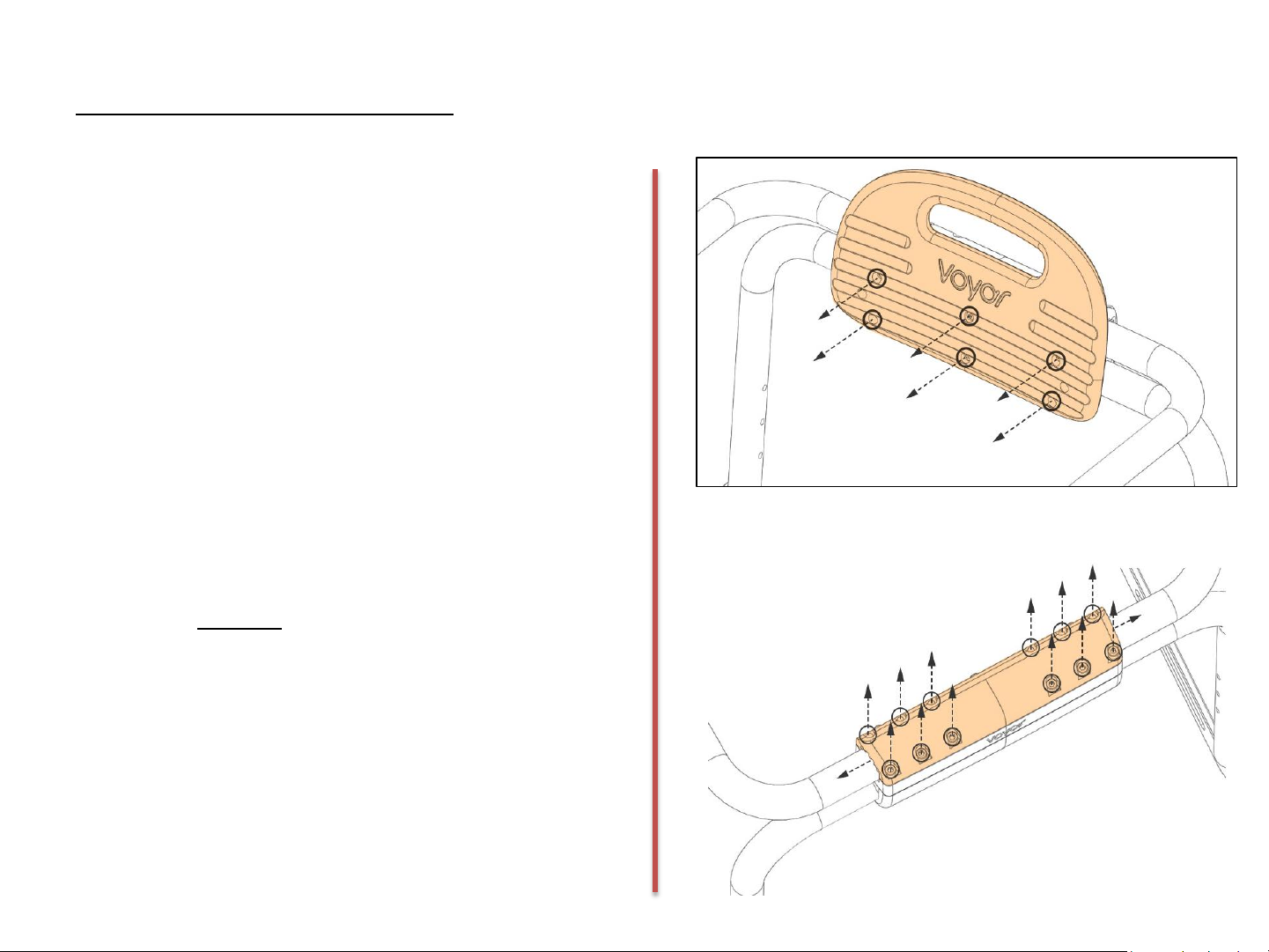
Adjusting & increasing width
1) There are 6 screws that holds the backrest
to the walker. Remove the 6 screws entirely
to remove the backrest (Allen key no. 3).
2) The frame clamp holds the frame of the
walker. Loosen the 12 screws (Allen key
no. 3) just enough to be able to slide the
frames); there is no need to remove them
entirely.
31
Page 32
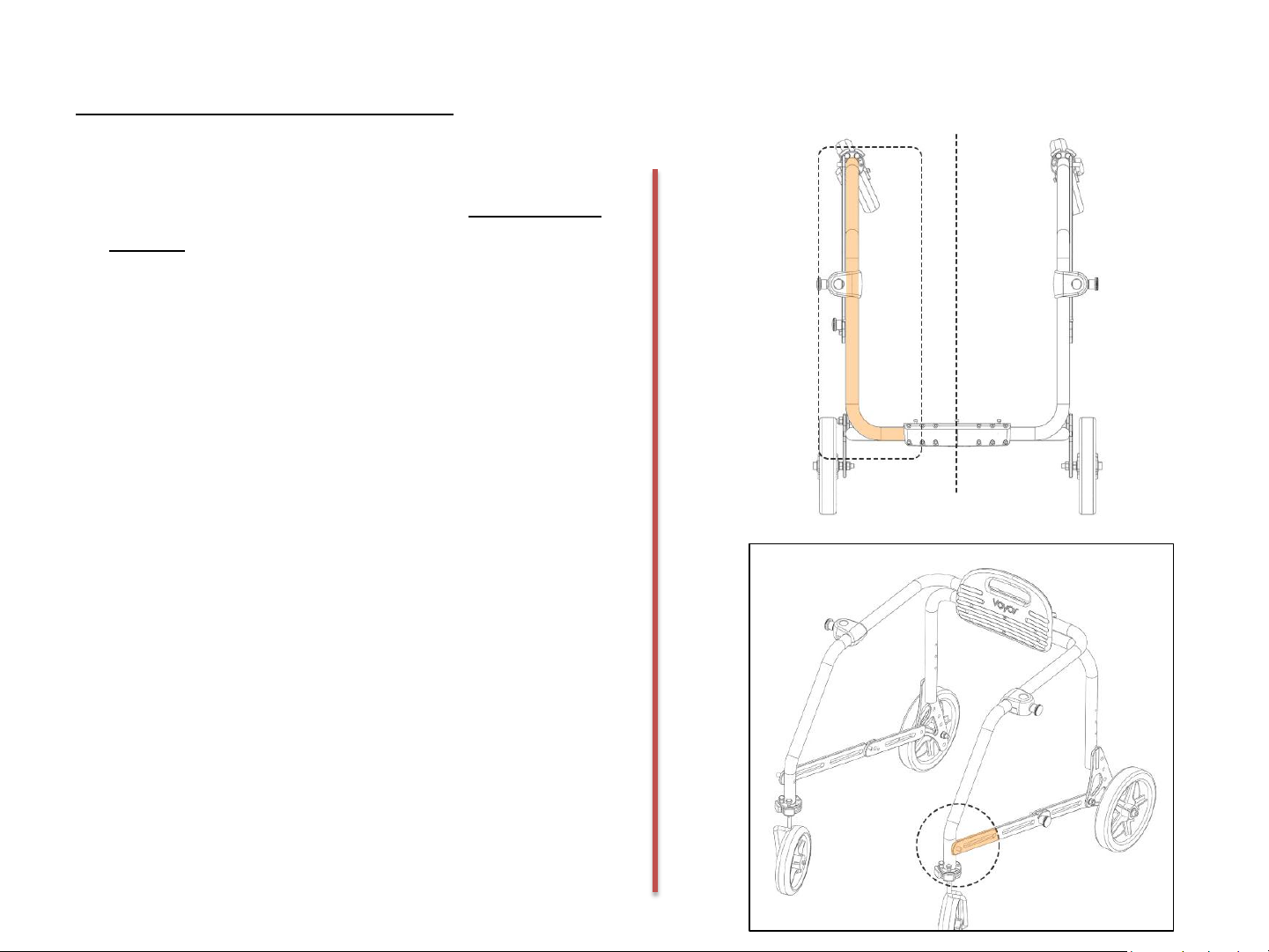
Adjusting & increasing width
3) Adjust the width of the walker one side at
a time.
4) Starting with the left side, locate intersection
L R
of frame & folding linkage. Detach the folding
linkage from the frame, which will be detailed
in the next step.
R
L
Folding linkage
32
Page 33
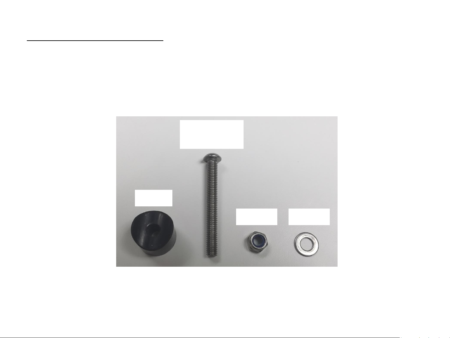
Adjusting & increasing width
Before moving on to Step 5, familiarize yourself with these parts first:
Spacer
Button-head
screw
Locknut
Washer
33
Page 34
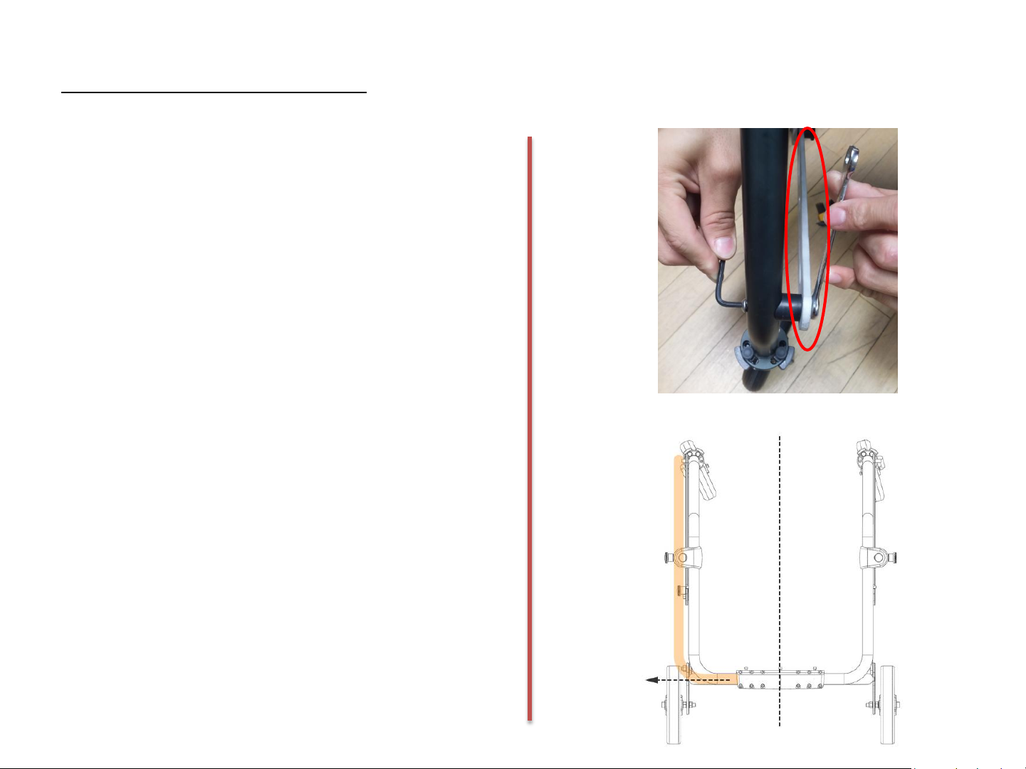
Adjusting & increasing width
5) Use spanner (no. 10) to grip onto the
locknut. Using Allen key (no. 4), loosen and
remove the button-head screw on the
other side. Remove the locknut, washer and
spacer as well. Rest the detached folding
linkage (circled in red) on the ground.
6) Return to the frame clamp section on the
same side (left). Slide the frame bar
outwards to the desired width (go to Step 9
to see the adjustment options).
L
R
34
Page 35
Adjusting & increasing width
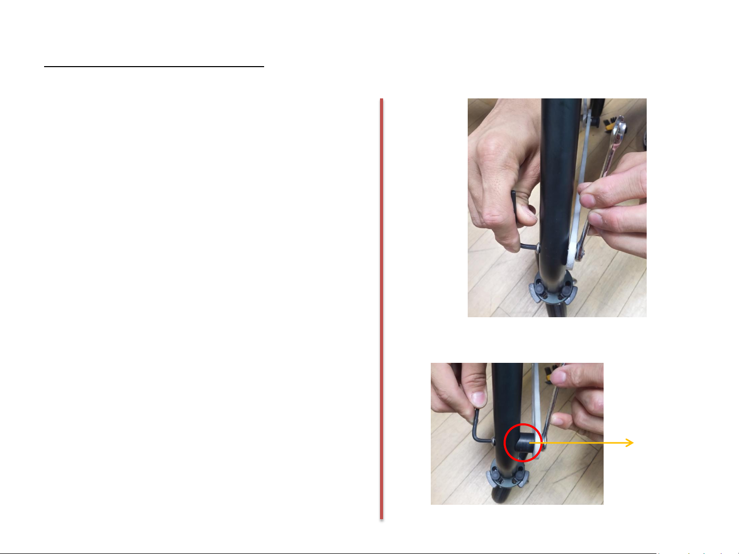
7) Return to the bottom section of the frame
and re-attach folding linkage. Using a shorter
screw (provided with the shipment), insert
into frame and folding linkage. Insert washer,
followed by the locknut (you do not need the
spacer since you are increasing width of the
walker). Using spanner and grip the locknut,
and use Allen key to tighten the
button-head screw.
Note: If you do need to decrease width of
walker back to its original state (smallest size),
you will need to insert the spacer back, before
you insert the locknut for tightening.
Spacer
35
Page 36
Adjusting & increasing width
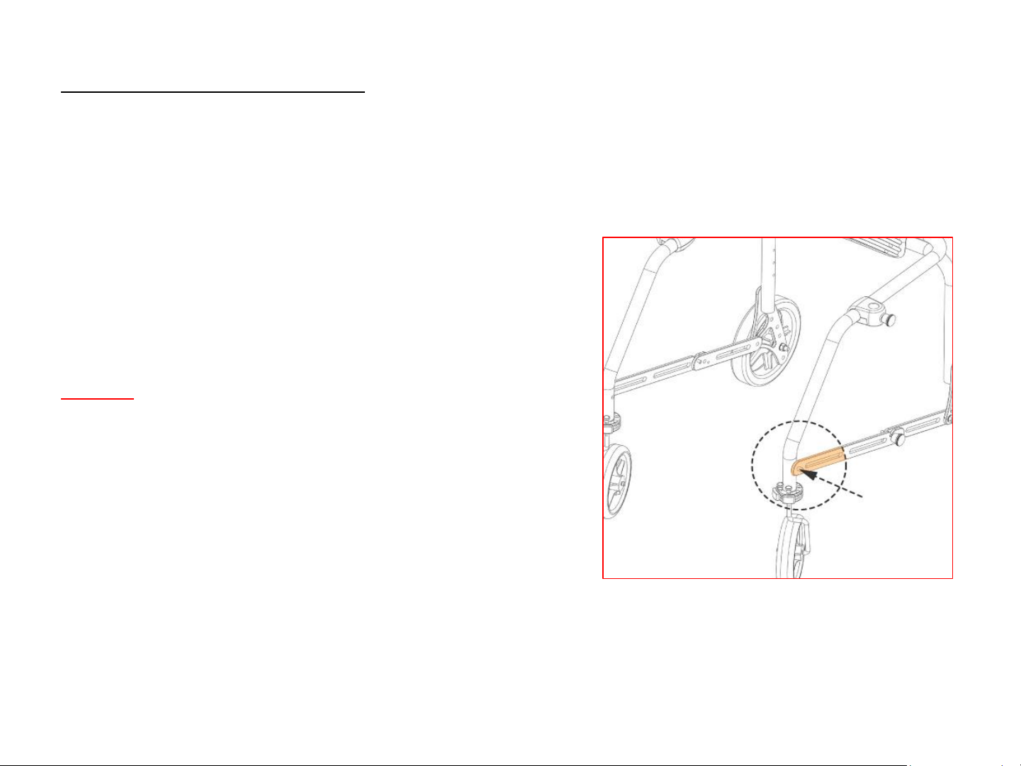
Please ensure the screw end with the locknut is
outside of the frame. This is to ensure the child’s
leg does not graze on this end.
Outside
of frame
36
Page 37
Adjusting & increasing width
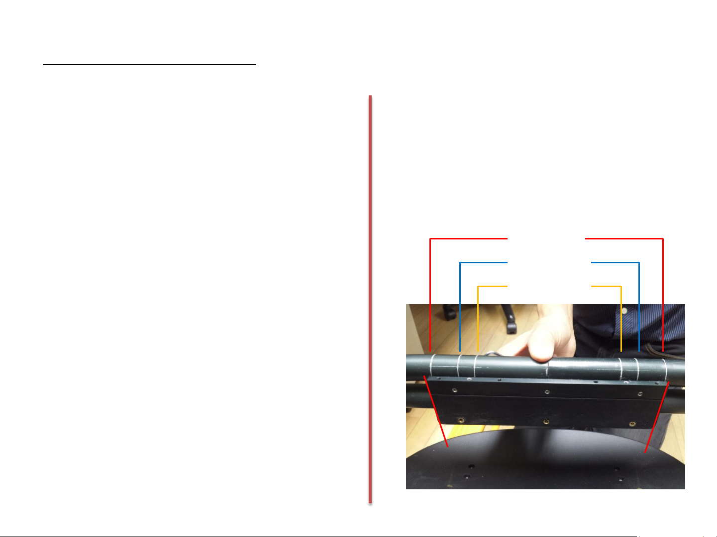
8) Repeat steps 4 to 7 on right side of the
walker.
9) Once the right side is done with adjustment,
do check to ensure the width adjustments
on both frame bars are equal (using the
markings as seen).
Small
Medium
Widest
Align markings with both sides of
the frame clamp.
37
Page 38
Adjusting & increasing width
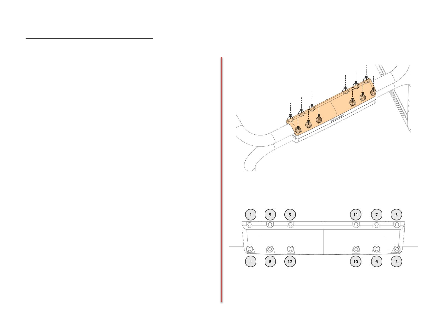
10) Once width adjustment is done, slowly
tighten back in the 12 screws in alternate
left-right sequence (in running sequence
1 to 12 as shown in diagram below).
38
Page 39
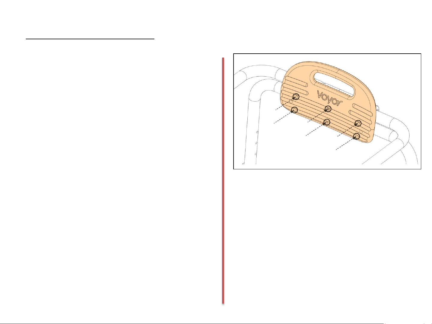
Adjusting & increasing width
11) Align backrest back onto the front of the
frame clamp. Insert back the 6 screws and
tighten them.
39
Page 40
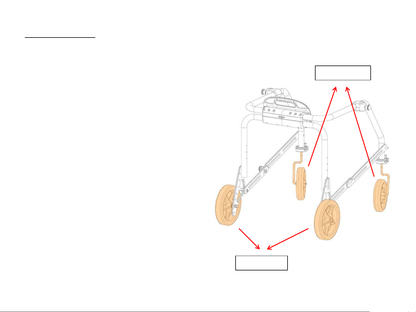
Adjusting height
Height adjustment is done via the wheels.
There are 2 parts – the back & front wheels.
Front wheels
Back wheels
40
Page 41
Adjusting height
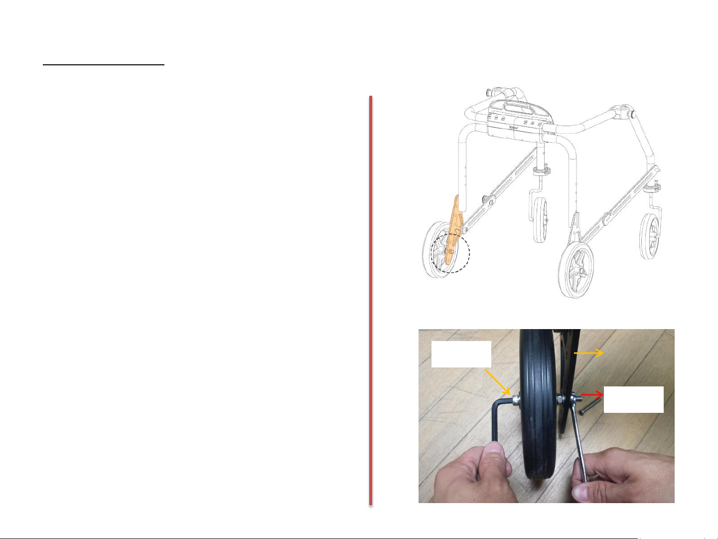
A) Back wheels adjustment
1) Starting with the left side, locate the A-plate
and the screws attached to the wheel.
2) Loosen the screw at the inner side of the
wheel. To do this, use allen key to grip on
to the outer screw on the wheel, and use
spanner to loosen and remove both the
inner screw + washer attached to the A-plate.
This will detach the wheel from the A-plate.
L
R
Outer A-plate
Inner
41
Page 42
Adjusting height
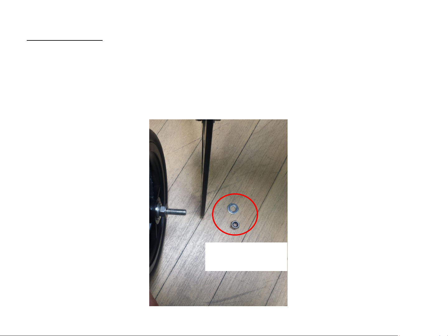
Before moving on to Step 3, do ensure that the screws that are attached to the wheels are
NOT removed. Only the inner screw & washers should be removed (shown below).
Inner screw +
washer removed
42
Page 43
Adjusting height
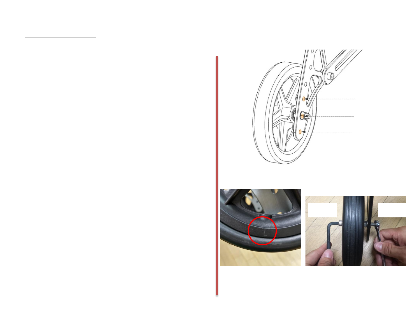
3) To increase the height, pull out the wheel,
and re-insert screw extension down 1
increment to achieve medium height. Moving
Lowest
down another increment will achieve
maximum height.
4) Insert back the wheel into A-plate, taking
note the ‘L’ side of the wheel is facing
OUTSIDE. Place the inner washer, followed by
the inner screw, through the A-plate. Using
Allen key to grip on to the outer screw, use
spanner to tighten the inner screw well.
Medium
Maximum
Inner Outer
43
Page 44
Adjusting height
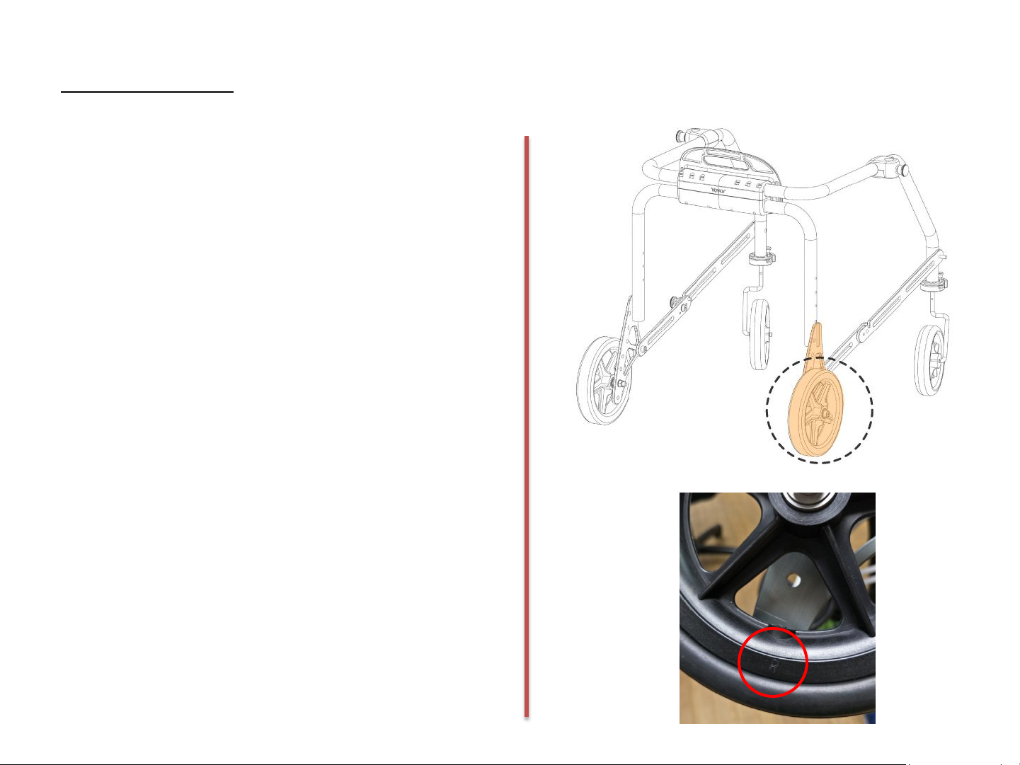
5) Repeat above steps for the other back wheel
(right side).
L
R
Do ensure the ‘R’ side of the wheel is facing
OUTSIDE after height adjustment.
44
Page 45
Adjusting height
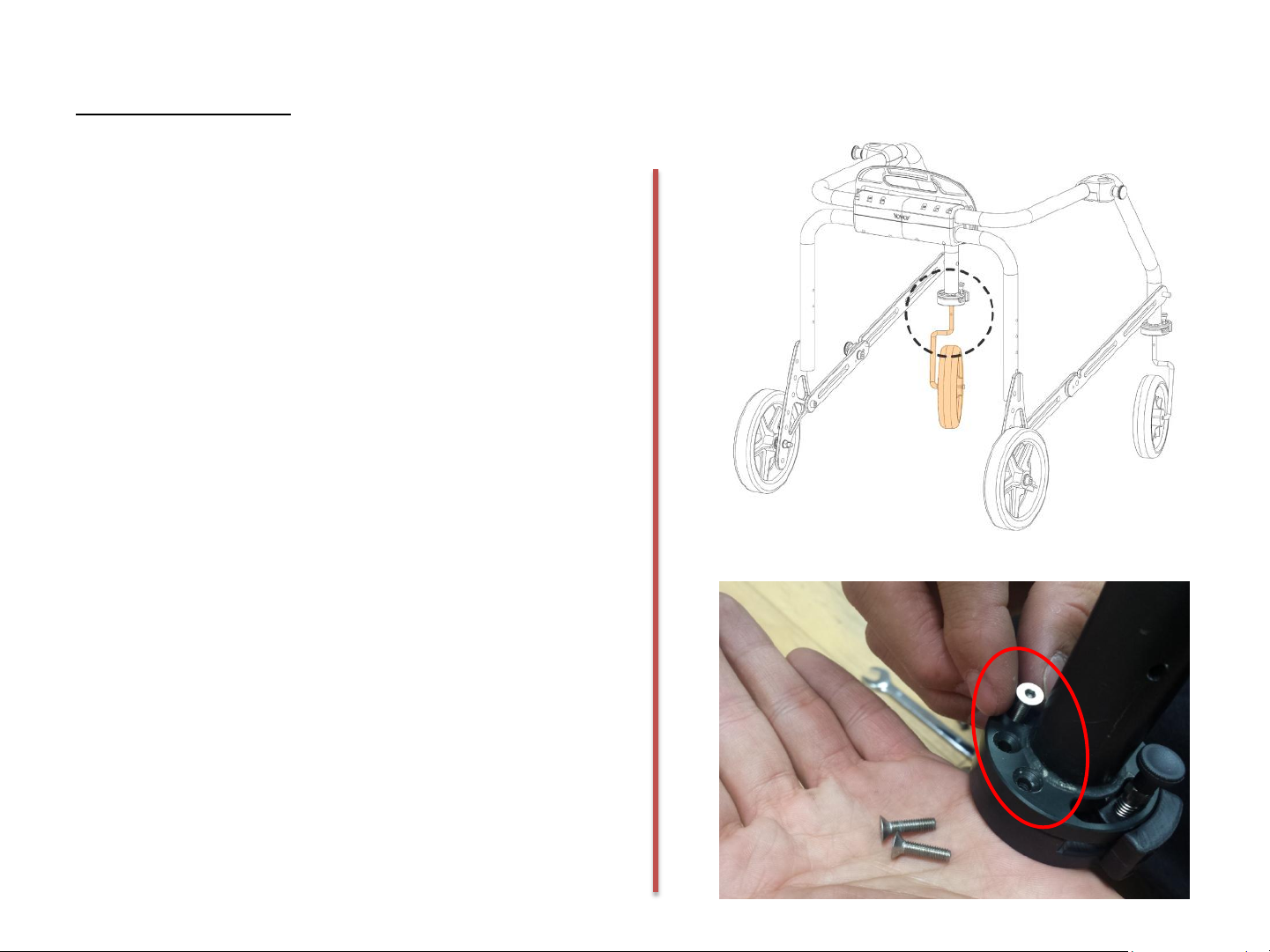
B) Front wheels adjustment
1) Starting with the left side, loosen and
remove the 3 screws as shown below
(use Allen key no. 2.5).
L R
45
Page 46
Adjusting height
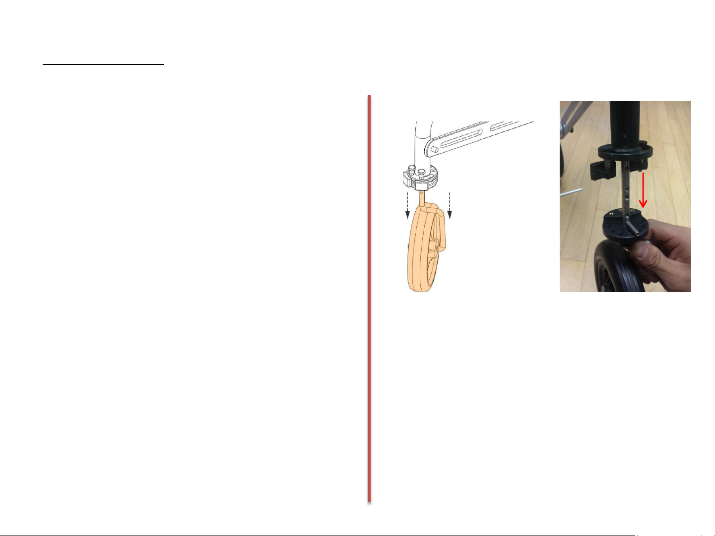
2) Lift up the walker slightly, and twist & pull
wheel shaft downwards to detach it from the
walker.
46
Page 47
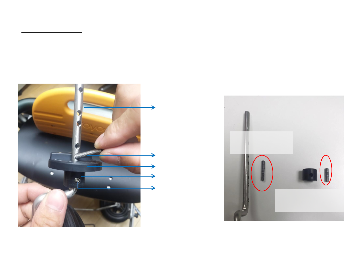
Adjusting height
Before moving on to Step 3, familiarize yourself with these parts first:
Main shaft
Main shaft screw
(longer)
Main shaft screw
Shaft plate
Shaft spacer
Spacer screw
Shaft spacer screw
(shorter)
47
Page 48
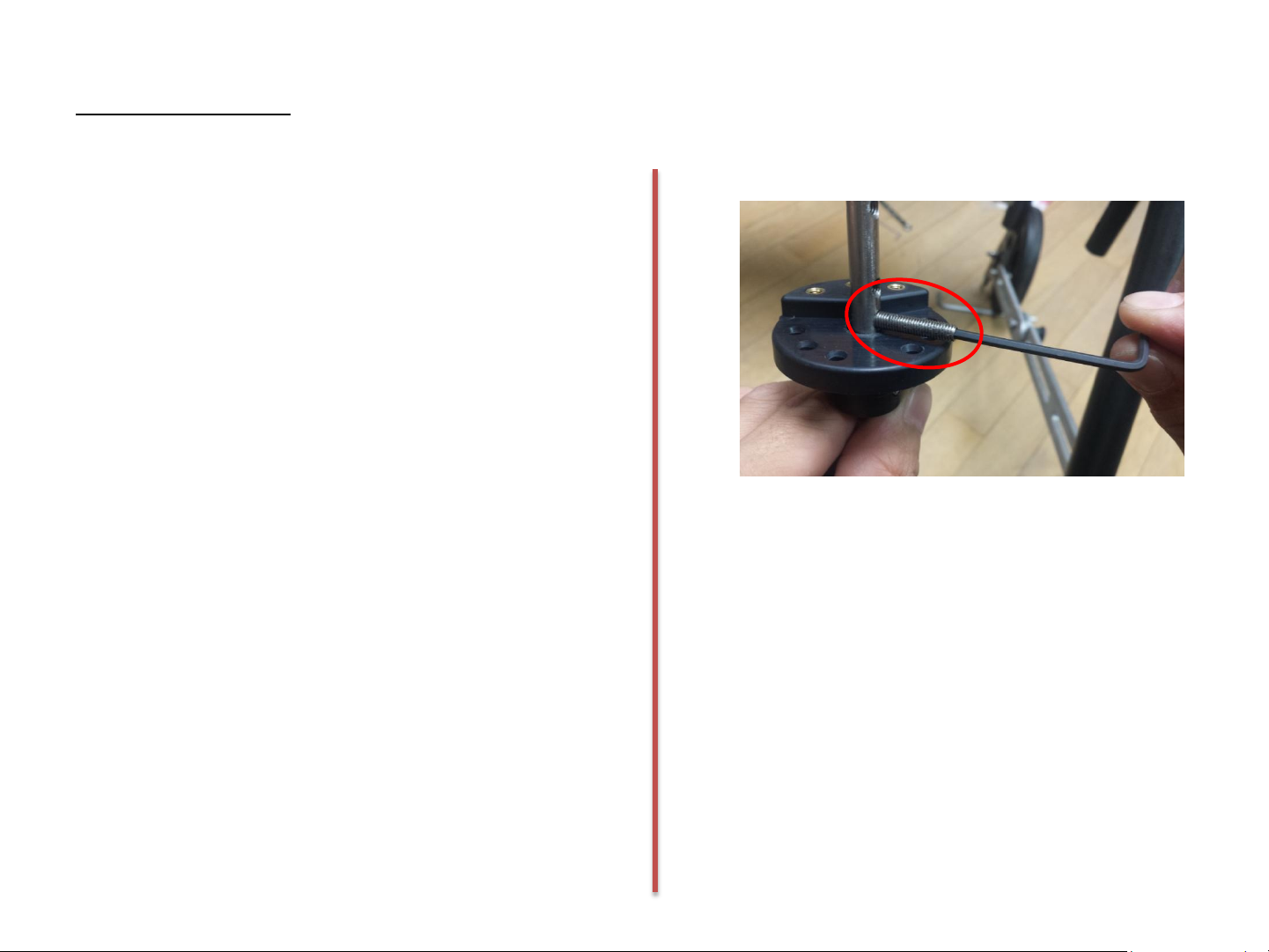
Adjusting height
3) Remove the main shaft screw (use Allen key
no. 2.5).
48
Page 49
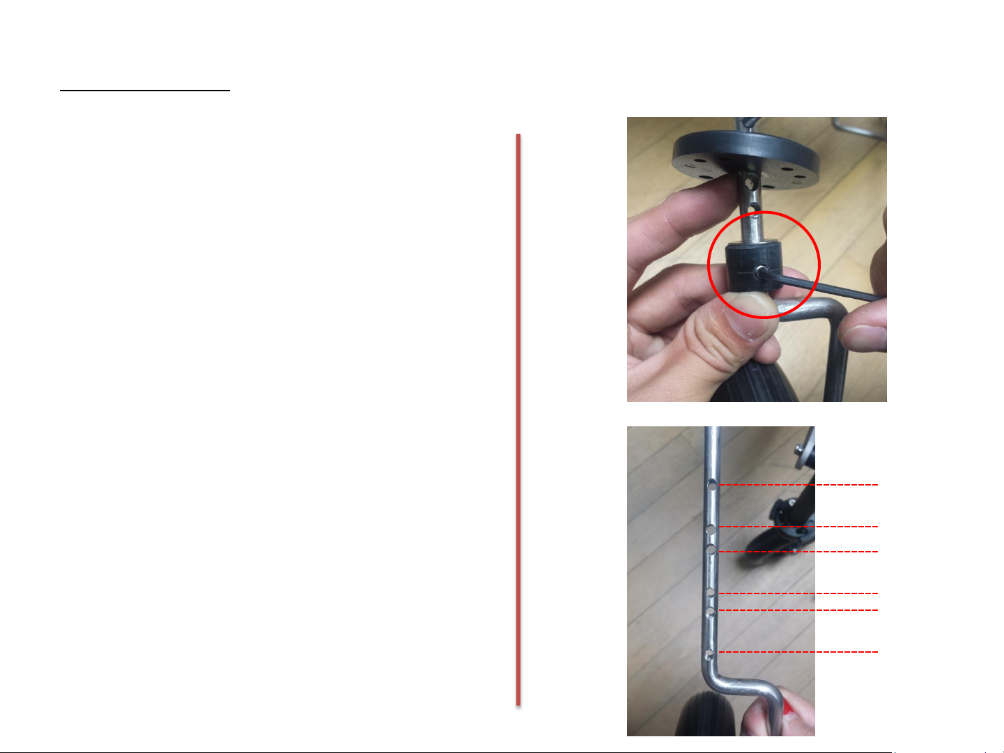
Adjusting height
4) The shaft spacer controls the height of the
front wheel. Loosen and remove the screw on
the spacer.
These hole numbers on the main shaft
determines the height setting:
6 – lowest
4 – intermediate
2 - highest
Slide the shaft spacer and align its hole to
the desired height setting. Re-insert screw
through the spacer & main shaft, and tighten.
Please ensure you set this front wheel’s height
according to the back wheel height setting –
A) Back wheels adjustment -> Step 3.
(lowest to lowest, medium to medium,
maximum to maximum).
1
2
3
4
5
6
49
Page 50
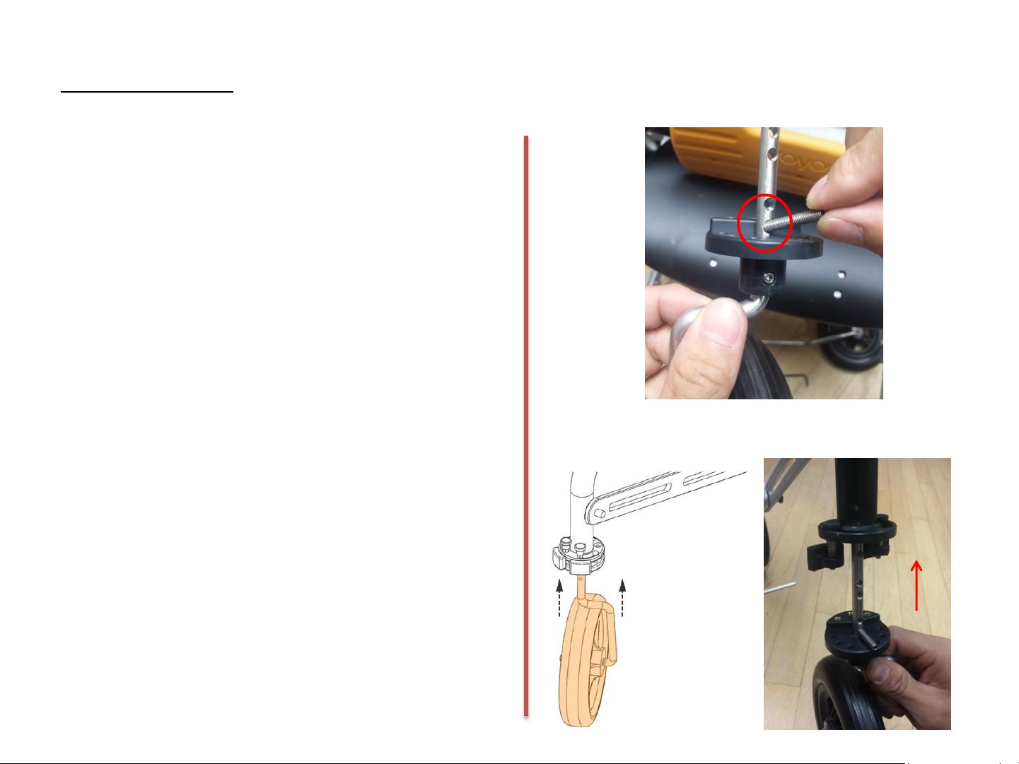
Adjusting height
5) The shaft plate now rest above the shaft
spacer. Insert the shaft screw into the hole
visible right above the plate.
6) Lifting up the walker, insert the wheel shaft
back into the walker. Align the shaft plate on
the wheel wit the shaft plate on the walker.
Insert the 3 screws removed earlier, and
tighten well.
50
Page 51
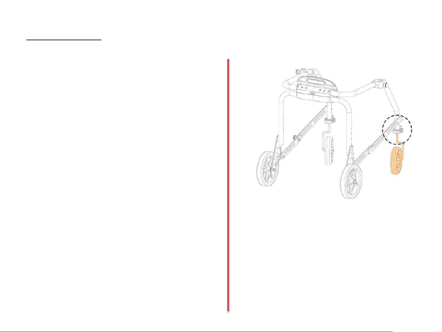
Adjusting height
7) Repeat above steps for other front wheel
(right side).
L R
51
Page 52

www.voyar.sg
 Loading...