

Page 1
WVOS541
O
a
WV
Digit
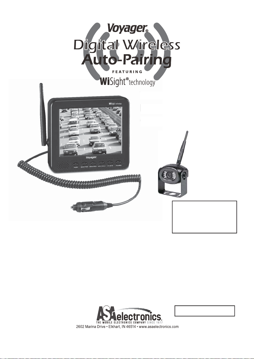
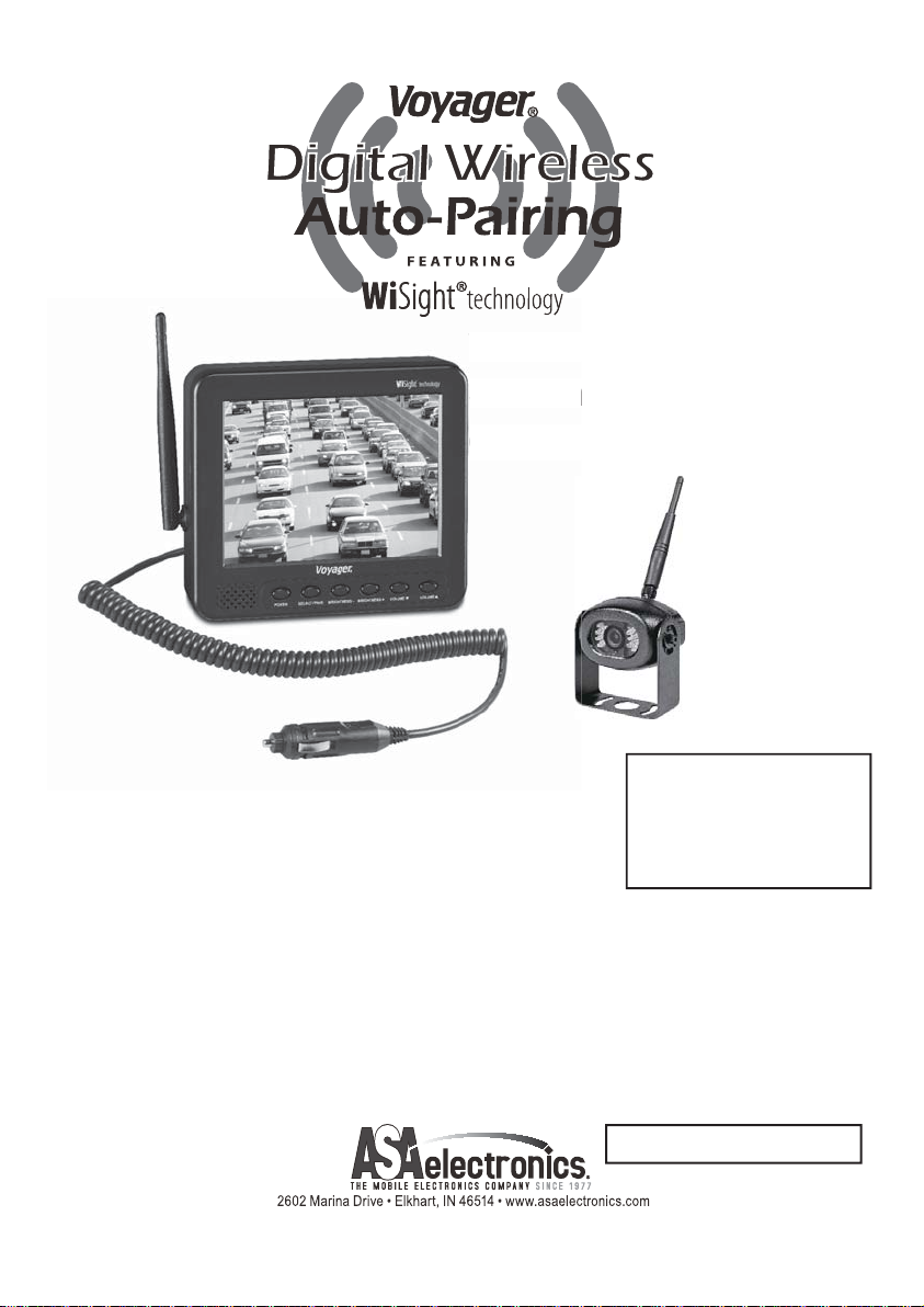
Digital Wireless
bs
Observation System
YOU WILL NEED:
● Voltage Meter
KEY FEATURES:
● Easy installation, fi ts most applications
● 5.6" monitor comes with suction cup mount and
12 Volt DC plug for easy portability
● Camera connects to rear clearance lights
● WiSight
● No interference
● Signal transmits through and around objects up to 60+ feet away
● Sharp,clear,uninterrupted picture
● Extend to 4 cameras available.
Package includes a 5.6" LCD color monitor, one 12 Volt DC accessory plug,
a suction cup monitor mount, one rear color camera, stainless steel hardware,
and non-corrosive camera mounting bracket.
®
technology- No cable or wiring necessary
● Water Proof Sealant
● Drill with 1/8" drill bit
● Phillips head screwdriver
PATENT PENDING
Features and specifi cations subject to change with out noticve
English
Page 2
INSTALLING THE CAMERA
1. Choose a location close to the rear clearance lights so you
can easily splice the power and ground connections.
2. Using a voltage meter, measure the clearance light wiring
to deter mine positive/negative polarity.
3. Connect the red wire from the camera to the positive
wire in the rear clearance lights.
4. Connect the black wire from the camera to the
negative wire in the rear clearance lights.
5. Pre-drill the screw holes for the mounting
bracket with an 1/8" drill bit.
6. Apply a weather proof sealant to the pre-drilled holes.
7. Align the bracket to the holes.
8. Install the bracket with the supplied Tapping P/H screws with washers.
9. Apply additional sealant to the screw heads and bracket to ensure a
weather proof seal.
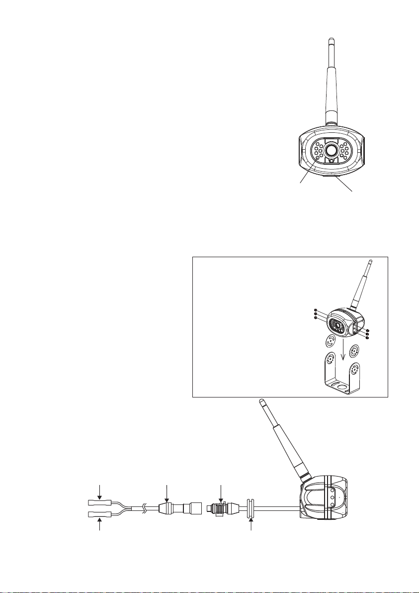
10. Align the camera in the bracket
Installation
(Figure 1).
11. Install with the supplied Hex
Socket Head stainless screws
and larger washers in the
corresponding holes(Figure 2).
Screw For Use
● Hex Socket Head M4xM6L
stainless screw
● Flat Washers 4.5x9.5x1mm
● Stainless Allen wrench
12. Camera should be adjusted for
optimum view before these
screws are fully tightened.
LED Assisted
Illumination
FIGURE 2
FIGURE 1
Microphone
Standard Cable
12V DC
Red
Black
Ground/Shield Grommet To Seal Through
Connector
Waterproof Camera
Connector
Vehicle Exterior
EN-01
Page 3
INSTALLING THE MONITOR
1. Plug power cable into the back of the monitor.
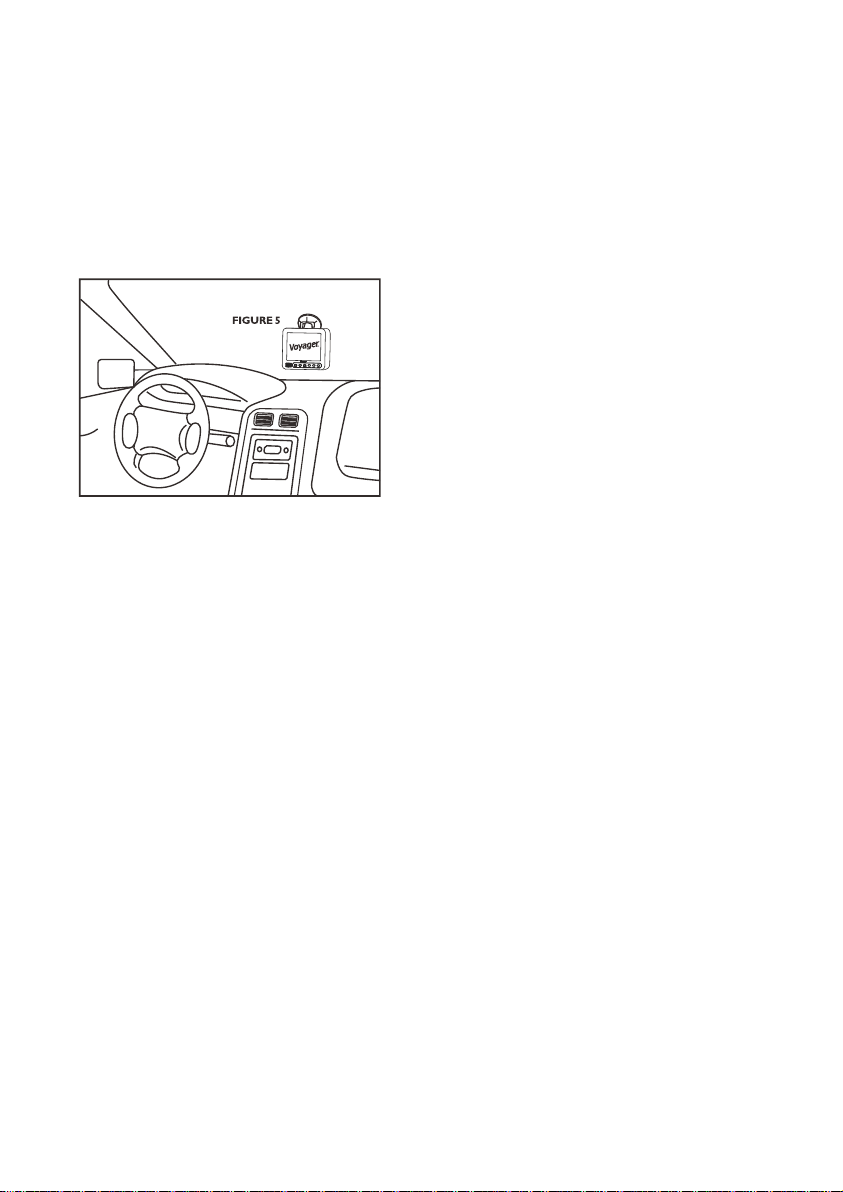
2. Attach the suction cup bracket to the rear of the monitor with the supplied screw.
3. Locate fl at section of glass on your windshield (that does not block your vision)
and apply suction cup. Snap the lever into the locked position (Figure 5).
4. Connect the power cord to a 12 Volt DC outlet.
5. Align the antenna to its upright position, parallel to the monitor.
OPERATION
1. Press the power button on the monitor and turn on your vehicle's parking lights.
2. In the top right corner of the monitor, you will see the signal strength meter.
3. Adjust the suction cup bracket to provide the best viewing angle.
4. Press and hold the "POWER" button for 5 seconds and release to
setup monitor " Mirror ON" or "Mirror OFF"
PAIRING PROCESS
This system has Auto-Pairing function. If your monitor is not receiving a signal from
the camera; the two may not be paired correctly.
1. Monitor must be connected to 12 Volt DC power supply.
2. Press the SELECT/PAIR button on the front of the monitor expected mode & select the
appropriate AV source (AV1-AV4)
3. Press and hold the "SELECT/PAIR" button on the front of the monitor for 5 seconds and
release. (Monitor will display "PAIRING START")
4. Apply 12 Volt DC power to the camera.(Camera 1 - Camera 4 corresponding to
Monitor's AV1 - AV4)
If done correctly, monitor will display "SAVE DATA". If pairing is not successful, the
monitor will display "PAIRING FAIL". if you receive this message, repeat steps 3-4.
EN-02
Page 4

CAMERA-MONITOR WARNINGS!
1. Camera/Monitor system aids in the use of, but does not replace vehicle
side/rear-view mirrors.
2. Objects in Camera/Monitor view are closer than they appear.
When backing up, processed cautiously and be prepared to stop.
IMPORTANT NOTE:
To comply with the FCC RF exposure compliance requirements, the antenna(s) used
for this transmitter must be installed to provide a separation distance of at least 20 cm
from all persons and must not be co-located or operating in conjunction with any other
antenna or transmitter. No change to the antenna or the device is permitted.
Any change to the antenna or the device could result in the device exceeding the RF
exposure requirements and void user's authority to operate the device.
NOTICE 1 :
The changes or modifi cations not expressly approved by the party responsible for
compliance could void the user’s authority to operate the equipment.
NOTICE 2:
Our WiSight wireless technology operates at nearly the same performance level as
a wired system. However, slight delays and signal reductions are possible due to
application or environmental factors.
It is recommended to maintain at least three feet in between any RF transmitting/
receiving devices including the WiSight components. This can include, but not limited
to, in-vehicle Wi-Fi systems, personal Wi-Fi hotspots, Bluetooth devices or additional
wireless monitors & cameras.
If you have a Voyager WiSight Digital Wireless Observation System along with any other
device that transmits or receives and you are experiencing diffi culty in operating the
system, the device(s) may be too close to either the WiSight Monitor or Camera.
Change the placement to at least three feet between devices and re-test for proper
operation.
TROUBLE SHOOTING
Monitor will not turn on.
Monitor display "No Signal".
Intermittent reception.
For further technical support call: 1-877-305-0445
- Check power cord connection at monitor
and 12VDC socket.
- Check fuse in cigarette socket adapter.
- Check 12VDC power at camera.
- Make sure antenna is tight and pointed
correctly.
- Make sure monitor is set to AV1.
- Try manually pairing the system.
see pairing Process for instructions.
- Make sure antenna is tight and installed
vertically.
EN-03
Page 5
WVOS541
OS
m
i
WV
Sistema de observación
iste
digital inalámbrico
digital
NECESITARÁ:
PRINCIPALES CARACTERÍSTICAS :
● Instalación fácil, se ajusta a la mayoría de las aplicaciones
● El monitor de 5.6” viene con soporte de ventosa y enchufe
para CC de 12 voltios para mayor portabilidad
● La cámara se conecta a las luces de despeje traseras
● Tecnología WiSight
● No produce interferencia
● La señal se transmite a través de los objetos y alrededor de
ellos a distancias superiores a los 60 pies
● Imagen nítida, clara e ininterrumpida
● Aplicable a 4 cámaras disponibles
El paquete incluye un monitor LCD a color de 5,6", un enchufe para accesorios CC de 12
voltios, un soporte de ventosa para monitor, una cámara a color trasera, herrajes de acero
inoxidable y un soporte de montaje no corrosivo para cámara.
®
- No requiere cableado
● Voltímetro
● Impermeabilizante
● Taladro con broca de 1/8"
● Destornillador de cabeza
● Phillips
PATENTE PENDIENTE
Características y especifi caciones sujetas a cambios sin previo aviso.
Español
Page 6

Instalación De La Cámara
1. Escoja un lugar cerca de las luces de despeje traseras para que
pueda empalmar fácilmente las conexiones de alimentación y tierra.
2. Con un voltímetro, mida el cableado de las luces de despeje
para determinar la polaridad positiva/negativa.
3. Conecte el hilo rojo de la cámara al hilo positivo en las luces
de despeje traseras.
4. Conecte el hilo negro de la cámara al hilo negativo en las
luces de despeje traseras.
5. Pretaladre los orifi cios de los tornillos para el soporte de
montaje con un taladro con broca de 1/8".
6. Aplique un impermeabilizante a los orifi cios pretaladrados.
7. Alinee el soporte con los orifi cios.
8. Instale el soporte con los tornillos C/P con arandelas que vienen con el dispositivo.
9. Para garantizar un sellado impermeable,aplique impermeabilizante también a las
cabezas de los tornillos y al soporte.
10. Alinee la cámara en el soporte
(Figura 1).
Instalación
11. Instale con los tornillos inoxidables
M4X6L de cabeza hexagonal y
las arandelas (Figura 2).
12. La cámara debe ajustarse para
obtener la vista óptima antes de
Instalación de tornillos
● Tornillos inoxidables
M4x6L de cabeza hexagonal
● Arandelas planas
4.5x9.5x1 mm inoxidables
● Llave Allen
apretar completamente estos
tornillos.
Iluminación
asistida por
LED
FIGURE 2
FIGURE 1
Micrófono
CC 12V
Rojo
Negro
Tierra/Blindaje Sello arandela al exterior
Conector de
cable estándar
Conector de cámara
Impermeable
del Vehículo
ES-01
Page 7

Instalacion De La Pantalla
1. Conecte el cable de energía a la parte posterior de la pantalla.
2. Una el soporte ventosa a la parte posterior de la pantalla con los tornillos
suministrados.
3. Elija una zona plana en su parabrisas (que no obstaculice su visión) y ponga la
ventosa. Coloque la palanca en la posición de bloqueo (Figura 5).
4. Conecte el cable de energía a la salida de 12 Voltios OC.
5. Alinee la antena en posición vertical, paralela a la pantalla.
Operacion
1. Presione el botón power en la pantalla y encienda las luces del vehículo.
2. En la esquina superior derecha de la pantalla verá el medidor de intensidad
de la señal.
3. Mueva el soporte ventosa para un mejor ángulo de visión.
4. Presione y mantenga el botón "POWER" por 5 segundos y luego suelte para
confi gurar la opción "Mirror ON" o "Mirror OFF"
Proceso De Sincronizacion
Este Sistema tiene una función de Asociación Automática. Si su monitor no recibe señal
de la cámara, puede que no estén asociadas correctamente.
1. El monitor debe estar conectado a la alimentación de 12 Voltios CC.
2. Presiona el botón "SELECT/PAIR" en la parte delantera del monitor del modo experto y
elige la fuente AV adecuada (AV1-AV4).
3. Mantenga pulsado el botón "SELECT / PAIR" situado en la zona frontal del monitor
durante 5 segundos y suéltelo. (El monitor mostrará "START PAIRING")
4. Aplica a la cámara una tensión de 12 V en continua (Cámara 1 - Cámara 4 orresponden
a los monitores AV1 - AV 4)
Si se ha realizado correctamente, el monitor mostrara “SAVE DATA”. Si la asociación no es
exitosa, el monitor mostrara “PAIRING FAIL”. Si recibe este mensaje repita los pasos 3-4.
ES-02
Page 8

¡Advertencias sobre la cámara y el monitor!
1. El sistema de cámara/monitor ayuda a usar los espejos de vista lateral/trasera del
vehículo, pero no los reemplaza.
2. Los objetos en vista de cámara/monitor están más cerca de lo que parecen.
Al retroceder, avance con cautela y esté preparado para detenerse.
Nota Importante:
Para obedecer los requisitos de cumplimiento sobre exposición RF de la FCC, La(s)
antena(s) utilizada(s) con este transmisor debe(n) ser instalada(s) de forma que de(n)
una distancia de separación de por lo menos 20 cm con cualquier persona y no debe(n)
estar ubicada(s) o funcionar conjuntamente con otra antena o transmisor.no se permiten
cambios a la antena o al dispositivo. Podría hacer que el dispositivo exceda los
requisitos sobre exposición
Aviso 1 :
Los cambios o modifi caciones no aprobados expresamente por la parte responsable
del cumplimiento podrían invalidar la autoridad del usuario para operar el equipo.
Aviso 2:
Nuestra tecnología inalámbrica WiSight opera casi al mismo nivel de rendimiento que
un sistema alámbrico. Sin embargo, puede haber ligeros retrasos y reducciones de
señal debido a algunos factores de la aplicación o el entorno.
Se recomienda mantener al menos un metro (tres pies) de distancia entre cualquier
dispositivo transmisor/receptor de RF, incluidos los componentes de WiSight.
Esto puede incluir sistemas Wi-Fi dentro del vehículo, zonas de conexión personal a
Wi-Fi, dispositivos Bluetooth o monitores y cámaras inalámbricos adicionales,
sin limitarse a ellos.
Si usted tiene un sistema de observación digital Voyager WiSight Digital Wireless
Observation System ubicado junto a cualquier otro dispositivo transmisor o receptor,
y experimenta difi cultades para operar el sistema, esto puede deberse a que este
dispositivo o dispositivos se encuentran demasiado próximos al monitor o cámara
WiSight.
Cambie su ubicación poniéndolos a una distancia de al menos un metro (tres pies)
entre los dispositivos y vuelva a probar su funcionamiento correcto.
Localización De Fallas
El monitor no enciende
El monitor muestra
“No Signal”.
- Revise la conexión del cable eléctrico al monitor
y a la toma de CC 12V.
- Revise el fusible en el adaptador del encendedor
de cigarrillos.
- Compruebe la alimentación de CC 12V en la cámara.
- Compruebe que la antena esté firme y apuntada
correctamente.
- Compruebe que el monitor esté configurado en AV1.
- Trate de conectar manualmente el sistema.
Vea instrucciones en Proceso de Conexión.
Recepción intermitente.
Para recibir soporte técnico llame al: 1-877-305-0445
- Compruebe que la antena esté firme e instalada
verticalmente.
ES-03
Page 9

WVOS541
OS
WV
stè
Système d'observation
umé
numérique sans fi l
Instruments nécessaires :
CARACTÉRISTIQUES PRINCIPALES :
● Installation simple convenant à la plupart des applications.
● Le moniteur 14,2 cm est équipé d'un support à ventouse
et d'une prise 12 Volt CC pour faciliter le transport
● La caméra se connecte aux feux arrière
● Technologie WiSight
● Pas d'interférence
● Le signal passe à travers et autour des objets jusqu'à plus de 18 mètres
● Image nette, claire et continue
● Étendre aux 4 caméras disponibles.
Le pack inclut un moniteur couleur LCD 14,2 cm, une prise accessoire de 12 Volt CC, un
support à ventouse intégré au moniteur, une caméra couleur arrière, des accessoires en acier
inoxydable et un support de montage caméra anti-corrosion.
®
- Sans aucun câble ou câblage
● Voltmètre
● Mastic étanche
● Perceuse à mèche 3,17 mm
● Tournevis à tête cruciforme
BREVET EN INSTANCE
Les caractéristiques et spécifi cations sont sujets à changement avec les noticve
Français
Page 10

Installation De La Caméra
1. Choisir un endroit proche des feux arrières pour un raccordement
facile au courant et aux connexions de masse.
2. À l'aide d'un voltmètre, mesurez le câblage des feux pour
déterminer la polarité positive/négative.
3. Reliez le câble rouge de la caméra au câble positif des feux
arrière de gabarit.
4. Reliez le câble noir de la caméra au câble négatif des feux
arrière de gabarit.
5. Percez les avant-trous du support de montage avec
une mèche de 3,17 mm.
6. Appliquez un mastic étanche sur les avant-trous.
7. Alignez le support avec les trous.
8. Installez le support avec les vis taraudeuses P/H et les rondelles fournies.
9. Appliquez une couche supplémentaire de mastic sur les têtes des vis et sur le
support pour assurer l'étanchéité du joint.
10. Alignez la caméra sur le support
Installation
(Figure 1).
11. Installez-la avec les vis inox
hexagonales et les grandes
rondelles fournies dans les trous
(Figure 2).
Vis à utiliser
● Vis inox hexagonales M4 X 6L
rondelles
● Plates 4,5x9,5x1 mm clé
● Allen inox
12. La caméra doit être ajustée pour
offrir une vision optimale avant de
resserrer complètement les vis.
Éclairage LED
Microphone
FIGURE 2
FIGURE 1
12V CC
Rouge
Noir
Masse/Blindage
Connecteur câble
standard
FR-01
Connecteur caméra
étanche
Oeillet à sceller par
l'extérieur du véhicule
Page 11

Installation Du Moniteur
1. Branchez le câble d'alimentation dans l'arrière du moniteur.
2. Fixez le support aspiration à l'arrière du moniteur avec les vis fournies.
3. Localisez la section de verre plat sur votre pare-brise (qui ne bloque pas votre vision)
et appliquez le support d’ aspiration. Enclenchez le levier dans la position de
verrouillage (fi gure 5).
4. Branchez le cordon d'alimentation à une prise de 12 volts DC.
5. Alignez l'antenne dans sa position verticale, parallèle à l'écran.
Fonctionnement
1. Appuyez sur le bouton d'alimentation sur le moniteur et allumez les feux de
stationnement de votre véhicule.
2. Dans Le coin supérieur droit de l'écran, vous verrez l'indicateur de puissance du signal.
3. Réglez le support d’aspiration pour fournir le meilleur angle de vue.
4. Appuyez et maintenez enfoncé le bouton "POWER" (Alimentation) pendant
5 secondes, puis relâchez pour confi gurer le moniteur sur "Mirror ON" ou
"Mirror OFF".
Processus De Jumelage
Ce système dispose d'une fonction d'auto-couplage. Si votre moniteur ne reçoit pas le
signal de la caméra; les deux ne peuvent être couplés correctement.
1. Le moniteur doit être connecté à une alimentation électrique de 12 volts DC.
2. Appuyez sur le bouton SELECT/PAIR sur le front de la mode moniteur prévu et
sélectionnez la source AV appropriée (AV1-AV4).
2. Appuyez et maintenez le bouton "SELECT / PAIR" à l'avant de l'écran pendant 5
secondes et relâchez. (l'écran affi chera "PAIRING START")
3. Appliquez une alimentation de 12 volts CC à la caméra (Caméra 1 - Caméra 4
correspondant au Moniteur AV1 - AV4).
Si fait correctement, le moniteur affi chera " SAVE DATA". Si le couplage n'est pas réussi,
l'écran affi chera " PAIRING FAIL". Si vous obtenez ce message, répétez les étapes 3-4.
FR-02
Page 12

AVERTISSEMENTS SUR LE SYSTÈME DE CAMÉRA-MONITEUR !
1.Le système de caméra-moniteur ne substitue pas mais complète l'utilisation des
rétroviseurs latéraux/ arrières du véhicule.
2.Les objets visualisés sur le système de caméra-moniteur sont plus proches qu'ils ne
paraissent. Reculez avec prudence et soyez prêt à vous arrêter
REMARQUE IMPORTANTE :
Pour satisfaire aux exigences d’exposition aux radiofréquences de la FCC, l'antenne ou les
antennes utilisée(s) pour cet émetteur doivent être installées à une distance de séparation d'au
moins 20 cm de toute personne et ne doivent pas être situées au même endroit ou fonctionner
en même temps qu'une autre antenne ou un autre émetteur. Aucune modifi cation de l’antenne ou
de l’appareil n’est autorisée. Toute modifi cation de l'antenne ou de l'appareil pourrait entraîner le
dépassement du seuil d'exposition aux radiofréquences établi par la FCC et entraîner la perte du
droit d'utilisation de cet équipement.de cet équipement.
AVIS 1 :
Tout changement ou modifi cation n'ayant pas fait l'objet d'une autorisation expresse par la partie
responsable de la conformité peut entrainer la perte du droit d'utilisation de cet équipement.
AVIS 2 :
Notre technologie sans fi l WiSight offre pratiquement le même niveau de performances qu'un
système câblé. Toutefois, de légers retards et une diminution du signal sont possibles en raison de
l'application ou de facteurs ambiants.
Il est conseillé de laisser une distance d’au moins 1 mètre (3 pieds) entre tout appareil transmeteur/
récepteur, y compris les composants de WiSight. Cela peut inclure des systèmes Wi-Fi à l’intérieur
du véhicule, des points Wi-Fi personnels, des dispositifs Bluetooth ou des Caméras et des
moniteurs sans fi l supplémentaires, sans s’y limiter.
Si vous avez un système d’observation Voyager WiSight Digital Wireless Observation System avec
un autre dispositif qui transmet ou reçoit et que vous rencontrez des diffi cultés à faire fonctionner le
système, le(s) dispositif(s) pourraient être trop proches soit du moniteur, soit de la caméra WiSight.
Remettez au moins un mètre (3 pieds) entre les dispositifs et réessayez pour que cela fonctionne
bien.
Diagnostic De Panne
Le moniteur ne s'allume
pas.
Le moniteur affiche
« No Signal »
Réception instable.
Pour toute assistance technique plus détaillée, veuillez
contacter le : 1-877-305-0445
- Vérifi ez le branchement du cordon d'alimentation entre le
moniteur et la prise 12V CC.
- Vérifi ez le fusible de l'adaptateur allume-cigare.
- Vérifiez l'alimentation de la caméra sur 12V CC
- Assurez-vous que l'antenne est bien fixée et orientée
correctement.
- Assurez-vous que le moniteur est réglé sur AV1
- Essayez de connecter manuellement le système.
Voir Processus de connexion pour les instructions.
- Assurez-vous que l'antenne est bien installée et fixée
à la verticale.
FR-03
Page 13

WVOS541
OS
m
WV
iste
Sistema de observação
digital
digital sem fi o
VOCÊ IRÁ PRECISAR DE
● Voltímetro
CARACTERÍSTICAS PRINCIPAIS:
● Fácil instalação, atende à maioria das aplicações
● O monitor de 5.6” vem com suporte com ventosa e plugue
adaptador 12V DC para fácil portabilidade
● A câmera se conecta aos faróis de iluminação traseiros
● Tecnologia WiSight
● Sem interferências
● Transmissão do sinal através e ao redor de objetos a 8 metros de distância
● Imagem nítida, limpa e ininterrupta
● Amplie para disponibilizar 4 câmeras.
O pacote inclui um monitor colorido de LCD de 5.6”, um plugue adaptador 12V CC, um suporte
para montagem com ventosa, uma câmera traseira colorida, parafusos de aço inox e suporte
para montagem da câmera de material não corrosivo.
®
- não precisa de cabos ou fi os
● Vedante à prova d’água
● Furadeira e broca de 1/8"
● Chave phillips
PATENTE PENDENTE
Características e especifi cações sujeitas a mudanças sem aviso prévio.
Português
Page 14

Instalação Da Câmera
1. Escolha um local próximo aos faróis de iluminação traseiros para
fácil ligação de alimentação e terra.
2. Utilizando um voltímetro, teste a fi ação dos faróis para determinar a
polaridade positiva/negativa.
3. Conecte o fi o vermelho da câmera ao fi o positivo dos faróis de
iluminação traseiros.
4. Conecte o fi o preto da câmera ao fi o negativo dos faróis de
iluminação negativo dos faróis de iluminação traseiros.
5. Faça os furos para montagem do suporte usando
uma broca de 1/8".
6. Aplique vedante à prova d’água nos furos..
7. Alinhe o suporte com os furos.
8. Instale o suporte utilizando os parafusos de fi xação e as arruelas fornecidas.
9. Aplique uma camada extra de vedante às cabeças dos parafusos e ao suporte
para garantir total vedação.
10. Alinhe a câmera ao suporte
(Figura 1).
11. Instale a câmera utilizando os
parafusos Allen de aço inox e as
arruelas fornecidas conforme a
furação (Figura 2).
Instalação
Parafusos a serem usados
● Parafusos Allen de aço
inox M4 x 6L
● Arruelas lisas de aço
inox 4.5x9.5x1 mm
● Chave Allen
12. A câmera deve ser ajustada na
melhor posição antes de apertar
totalmente estes Parafusos.
Iluminação auxiliar
de LED
FIGURE 2
FIGURE 1
Microfone
12V CC
Vermelho
Preto
Terra/Proteção
Conector de
cabo padrão
Conector da câmera
a prova d'água
llhos de vedação exterior do
veículo
PT-01
Page 15

Instalar O Monitor
1. Coloque o cabo de alimentação de energia na parte de trás do monitor.
2. Fixe o suporte da ventosa na parte traseira do monitor com os parafusos fornecidos.
3. Localize uma zona plana do vidro do carro (e que não bloqueie a sua visão) e
aplique a ventosa. Trave a alavanca (Imagem 5).
4. Ligue o cabo da alimentação para uma saída de 12 Volt DC de energia.
5. Alinhe a antena na posição vertical, paralela ao monitor.
Funcionamento
1. Pressione o botão power no monitor e ligue as luzes do seu veículo.
2. No canto superior direito do monitor estará o sinal de rede.
3. Ajuste a ventosa de forma a dar-lhe o melhor angulo de visão do aparelho..
4. Pressione e segure o botão " POWER " durante 5 segundos e liberte-o de forma a
exibir o “Mirror ON” ou “Mirror OFF”
Processo De Emparelhamento
Este sistema tem a função de Pareamento Automático. Se seu monitor não está
recebendo sinal da sua câmera; talvez os dois não estão pareados corretamente.
1. O monitor deve ser conectado a uma fonte DC de 12 Volts.
2. Pressione o botão SELECT/PAIR na frente do monitor no modo esperado & selecione a
fonte AV apropriada (AV1-AV4).
3. Pressione e segure o botão " SELECT/PAIR " na frente do monitor por 5 segundos e
solte o botão. (Monitor exibirá " PAIRING START ")
4. Ligue 12 Volt DC a câmera.(Câmera 1 - Câmera 4 correspondendo ao AV1 - AV4 do
Monitor)
Se foi feito corretamente, o monitor exibirá " SAVE DATA ". Se o pareamento não foi feito
com sucesso, o monitor exibirá " PAIRING FAIL ". Se você receber esta mensagem,
repita os passos 3-4.
PT-02
Page 16

Avisos sobre o sistema Câmera-Monitor
1.O sistema câmera/monitor auxilia, mas não substitui o uso dos espelhos retrovisores
do veículo.
2.Os objetos mostrados no sistema câmera/monitor estão mais próximos do que
parecem. Ao dar a ré, dirija com cuidado e esteja alerta para parar imediatamente.
Nota Importante:
Para attender às exigências de exposição de RF da FCC, A(s) antena(s) utlilizada(s)
com este transmisor deve(m) ser instalada(s) a uma distância mínima de 20 cm de
qualquer pessoa e não deve(m) ser posicionada(s) ou funcionar em conjunto com
qualquer outra antena ou transmisor. não é permitida nenhuma alteração da antena ou
do dispositivo. Qualquer alteração desses itens poderá resultar em excesso aos limites
de exposição de RF e anulamento da permissão de uso do equipamento.
Atenção
Alterações ou modifi cações que não sejam expressamente aprovadas pela autoridade
competente poderão anular a permissão de uso do equipamento.
Nossa tecnologia sem fi o WiSlght™ opera com um nível de desempenho bastante
próximo de um sistema com fi os. Contudo, pode haver pequenos atrasos e reduções de
sinais devido a fatores de aplicação ou ambientais.
Recomenda-se manter a distância de pelo menos 3 pés de qualquer dispositivo
transmisor/receptor de RF, incluindo componentes WiSight. Isso inclui, mas não se
limita a sistemas de Wi-Fi instalados em veículos, hotspots pessoais, dispositivos de
Bluetooth ou monitores e câmeras sem fi o adicionais.
Se você possui um Sistema de observação digital sem fi o Voyager WiSight junto com
qualquer outro dispositivo transmissor ou receptor e estiver tendo difi culdades de operar
o sistema, o(s) dispositivo(s) pode(m) estar muito próximo(s) do montor ou da câmera
WiSight.
Mude o local de instalação deixando pelo menos 3 pés de distância entre os dispositivos
e faça um novo teste para verifi car se o sistema apresenta um funcionamento
adequado.
Solução De Problemas
O monitor não liga.
O monitor mostra
“No Signal” (Sem sinal).
Recepção intermitente.
Se precisar de suporte técnico, ligue: 1-877-305-0445
- Verifi que se o cabo de alimentação está ligado ao monitor
e à tomada de 12VCC.
- Verifi que o fusível do adaptador.
- Verifique a alimentção de 12VCDC da câmera.
- Verifique se a antena está firme e posicionada
corretamente.
- Verifique se o monitor está em AV1.
- Tente fazer a sincronização do sistema manualmente.
Consulte as instruções em na seção Processo de Sincronia.
- Verifique se a antena está firme e instalada verticalmente.
PT-03
MA-1504001-1R
 Loading...