

Page 1
Camera-Monitor Warnings!
1. Camera/monitor system aids in the use of, but does not replace vehicle
side/rear-view mirrors.
2. Objects in camera/monitor view are closer than they appear.
When backing up, proceed cautiously and be prepared to stop.
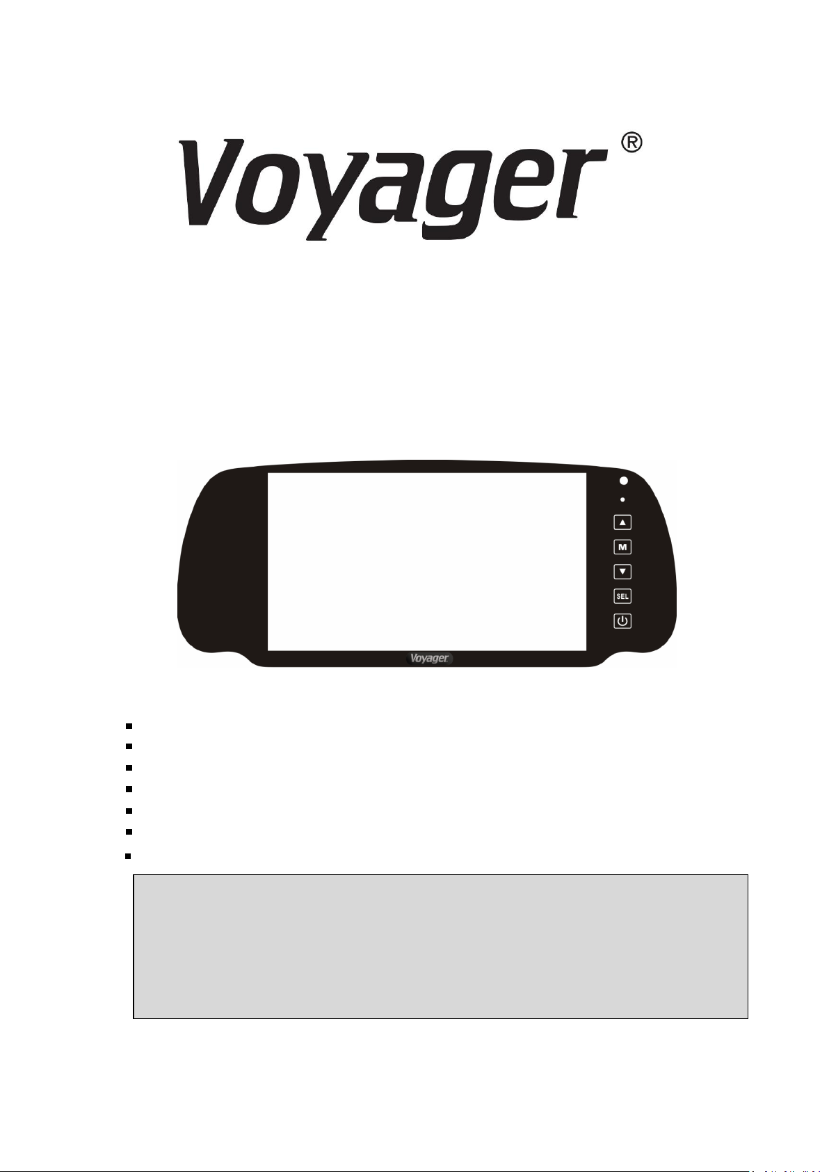
VOM73MM
7" COLOR TFT LCD 3 CAMERA MIRROR
MONITOR OWNER’S MANUAL
VOM73MM Features
High Performance Automotive Grade 7" Color LCD Panel
3 Camera Inputs
PAL/NTSC Compatible
Touch Buttons
Built-In Audio Speaker
Compatible with Voyager Standard Camera
Programmable Source Name OSD
Page 2

Page 3

1
VOM73MM
Important! - Please Read This Manual Before Installing!
Congratulations on your purchase of a Voyager VOM73MM LCD Observation Monitor.
With proper installation and use, your VOM73MM LCD is designed to provide you
with years of trouble-free operation. Please read this manual thoroughly beginning.
All Voyager Observation products are strictly intended to be installed as supplement
aid to standard rear-view mirror systems that may already exist in your vehicle.
Voyager Observation products are not intended for use as substitutes for-view mirror
devices, Or for any other standard motor vehicle equipment required to be installed
on vehicles by law.
While Voyager observation products contribute to improving the vehicle operator's
field Of view, these products are no substitute for proper defensive driving
techniques and Observance of traffic laws and motor vehicle safety regulations.
Warnings!
RED POWER WIRE MUST BE CONNECTED TO ACCESSORY TO AVOID CURRENT
DRAW IN THE KEY OFF POSIT.
Installation Location
It is unlawful in most jurisdictions for a person to drive a motor vehicle equipped
with a television viewer or screen located at any point forward of the back of the
driver's seat or in any location that is visible, directly or indirectly, to the driver while
operating the vehicle. The VOM73MM product is designed to be used primarily as a
rear observation device in conjunction with closed circuit camera. In any installations
where the VOM73MM is used to display television broadcasts or recorded video,
playback, installation location must adhere to local laws and regulations.
Tampering
To prevent electrical shock, DO NOT OPEN THE MONITOR CASE. There are potentially
harmful voltages inside the monitor. If evidence of tampering is detected,
There are no user serviceable parts inside the warranty will be considered void.
Moisture
While it will withstand short periods of exposure to moisture, this product does
contain sensitive electronic components and exposure should be limited by the
user/installer. This product is not designed for where constant exposure to moisture
or immersion can be encountered. This unit should NEVER be cleaned with a power
washer or used where direct power washer spray may be encountered.
Depth of view
OBJECT VIEWEDIN MONITORARE CLOSERTHAN THEYAPPEAR.
Page 4

2
PACKING CONTENTS
LCD MONITOR QTY.1
CABLE QTY.1
METAL BRACKET QTY.1 MACHINE SCREW QTY.4
Page 5

3
VOM73MM
Primary Function
-Pressing “UP” button increase brightness, contrast, color,
tint, volume or sleep.
- Pressing “DOWN” button decrease brightness, contrast,
color, tint, volume or sleep.
Secondary Function
-While in menu modes, the “UP” “DOWN” are used to
select the option setting.
CONTROLS AND OPERATION
1, POWER ON/OFF
-Press once turns unit on
-Press again turns unit off
2, SELECT
-Press “SEL” for switching CAM1 to CAM3.
3 & 5 , UP/DOWN
Page 6

4
PRESS TO SET UP EACH MENU
PRESS TO ENTER THE OSD
PRESS TO EXIT SET UP MENU
PRESS TO NAVIGATE FROM UP TO DOWN
THROUGH MENU OPTIONS
PRESS TO SELECT OPTION SETTING
PRESS TO GO BACK TO SET UP MENU
VOLUME
PRESS TO NAVIGATE FROM UP TO DOWN
PRESS TO INCREASE/DECREASE
SPEAKER VOLUME
PRESS TO GO BACK TO SET UP MENU
4,MENU
PRESS TO NAVIGATE LEFT/RIGHT
PICTURE
PICTURE
BRIGHTNESS 0 TO 100
CONTRAST 0 TO 100
COLOR 0 TO 100
TINT 0 TO 100
RESET
VOLUME
VOLUME 0 TO 100
\
Page 7

5
PRESS TO NAVIGATE FROM
UP TO DOWN
PRESS TO SELECT
OPTION SETTING
PRESS TO GO BACK TO
SET UP MENU
SYSTEM
PRESS TO NAVIGATE FROM UP TO DOWN
PRESS TO SELECT OPTION SETTING
PRESS TO GO BACK TO SET UP MENU
PRESET
PRESS TO NAVIGATE FROM UP TO DOWN
PRESS TO SELECT OPTION SETTING
PRESS TO GO BACK TO SET UP MENU
OPTION
LANG. ENGLISH, FRENCH,
SPANISH, PORTUGUESE
CAMERA 1 NORMAL, MIRROR
CAMERA 2 NORMAL, MIRROR
CAMERA 3 NORMAL, MIRROR
ZOOM 16:9, 4:3
OPTION
SYSTEM
S-COLOR NTSS, PAL
ACC 1-TIME 0SEC TO 10 SEC
ACC 2-TIME 0SEC TO 10 SEC
ACC 3-TIME 0SEC TO 10 SEC
SLEEP
SLEEP 0 TO 100
Page 8

6
VOM73MM
INSTALLATION INSTRUCTIONS
BEFORE YOU BEGIN INSTALLATION:
Before drilling be sure that no cable or wiring is on the other side. Clamp all wires
securely to reduce the possibility of them being damaged during installation and use.
Keep all cables away from hot or moving parts, and electrically noisy components.
Wiring Definitions:
Power connection: Pin 1 POWER IN DC (12V- 32V) -Red
Pin 2 GROUND -Black
Pin 3 CHANNEL 1 TRIGGER -Blue
Pin 4 CHANNEL 2 TRIGGER -Brown
Pin 5 CHANNEL 3 TRIGGER -Green
Camera 1 input: 4-Pin Connection for camera or camera extension cable
Camera 2 input: 4-Pin Connection for camera or camera extension cable
Camera 3 input: 4-Pin Connection for camera or camera extension cable
LCD panel: 13-Pin Large DIN cable connection to monitor
General:
1. Choose the monitor and camera locations.
2. Install all required cables in vehicle. A 3/4" (19mm) hole should be drilled for
passing camera cables through vehicle wall , barriers, etc.
Install split grommets where applicable. If additional cable protection is
required install convoluted tubing over the cable.
3. After cable/wiring has been routed and components in place temporarily
make all system connections and perform a system function check. If system
does not operate properly, see the troubleshooting section cable.
4. Make sure all cables are routed away from hot or moving parts, and away from
sharp edges. Secure cables with wire ties.
Backup (Rear) Camera
Rear-mounted cameras used for monitoring while backing up must be
connected to the CA 1 input. Trigger#1 must be connected to the reverse gear
light circuit in the vehicle.
Side Camera
If side monitoring cameras are installed, they should be connected to CA2 and
CA3. Trigger 2 and Trigger 3 should be connected to the vehicle's turn signal
circuits.
Page 9

7
CA3
TYPICAL SYSTEM CONNECTTION
REF #
WIRE COLOR
DESCRIPTION
1
RED
POWER IN DC 12~ DC 32V
2
BLACK
GROUND
3
BLUE
TRIGGER 1 (CA 1)
4
BROWN
TRIGGER 2 (CA 2)
5
GREEN
TRIGGER 3 (CA 3)
CA1
CA2
CAMERA X3
4-PIN FEMALE CAMERA
CONNECTOR
VOM73MM MONITOR
13-PIN LARGE DIN CONNECTOR
(MALE)
13-PIN LARGE DIN CONNECTOR
(FEMALE)
POWER/TRIGGERWIRE FUNCTIONS
Page 10

8
Operation Temperature Range : -20°C ~ + 70°C
Storage Temperature Range : -30°C ~ + 80°C
Max Humidity : 85%
Operation Voltage Range : DC 12V ~ 32V
Current Draw (typical) : Max 15W
Signal system : NTSC or PAL (Auto detection)
Video Aspect Ratio : 16 : 9
Input Level: 1Vp-p 75Ω
Audio Input Level : 150mV(Max)
Product Weight : 2.09 lbs/950g
Product Dimensions : Monitor Only Dimensions
9.76W × 4.25 H × 0.91Dinches
VOM73MM
Size/Type
7" (Analog) TFT LCD
Brightness
450 cd/m' ( typ )
Contrast Ratio
300
View Angles
Top (12 0'clock)
40°( typ)
(@CR≥1 0)
Bottom (6 0'clock)
60°( typ)
Horizontal
60°( typ)
Response Time
15ms
20ms
Back Light Type
LED
Back Light Life
50,000 hrs (min)
PRODUCT SPECIFICATIONS
LCD PANEL SPECIFICATIONS
 Loading...