

Page 1
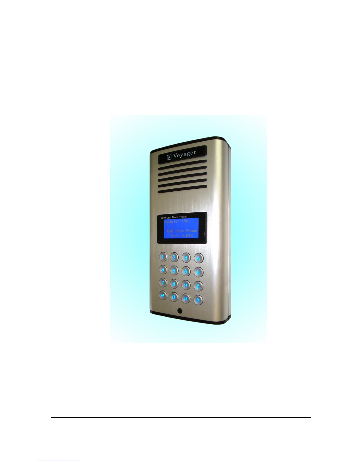
GSM Door Phone System
System Installation, Setting and Operation Manual
User Manual (750A-BL– V413E)
Please read this user manual completely before operating this system and keep it in a
safe place for future reference.
Page 2

1
TABLE OF CONTENTS
TABLE OF CONTENTS ……………………………………………….……………….
IMPORTANT SAFETY INSTRUCTIONS……………………………………………..
UNPACKING YOUR SYSTEM…………………..……………………………………..
SYSTEM DIAGRAMS
Front View ……………………………………………………………….………….
Back View ………………………………………………………………….……….
Wall Mounting Bracket …………………………………………………………….
INSTALLATION
GSM Door Phone……………………………………………………………………
Wiring Diagram & Wiring Instructions …………………………………………....
OPERATION
Power ON/OFF ……………………………………………………………………..
Dial Extension Number……………………………………………………………..
Manager Mode and Functions ……………………………………………….……
MANAGER SETTINGS
Change Manager Password ………………………………………………………
Manager Phone Number …………………..………………………………..…....
Set Seconds for Talking Time ………………………..………..………………….
Set Greetings ……………………..……………………………..………………….
VOLUME SETTING
Change Microphone Volume ……………………………………………………...
Change Speaker Volume …………………………………………………….........
Change Speaker Volume during Conversation ………………………………….
DOOR SETTING
Enable/Disable Door Lock Open by Password ………….………………………
Caller ID Open ………………………………………………………………………
Door Opening Time ……………………………………………………………...…
Door Relay Type ………….……………………………………………………...…
CALLING SETTING
Set Calling Time ………………………………………….…………………………
Change the Calling by List …………………………………………………………
Set the Incoming Call …………….……………..…………………………………
SUBSCRIBER
Subscriber ID Number Setup ……………………………………………………...
SUB-MENU………………………...…………….……………………………………….
CONTACT A SUBSCRIBER...………………………………………………………….
OPEN THE DOOR REMOTELY ……………………………………………………….
GO BACK TO STANDBY SCREEN AUTOMATICALLY ……………………..….…
SIM CARD ……………………………………………………………………………….
CALL MANAGER ……………………………………………………………………….
MASTER RESET…………………………………………………………………………
PC PROGRAMMING FUNCTION SETTING……….…………………………………
SMS CONTROL………………………………………………………………………….
1
2
3
4
5
6
7
8
10
10
11
11
12
12
13
13
14
14
15
15
16
16
16
17
17
18
19
19
20
20
20
20
20
21
24
Page 3

2
Thank you for purchasing the GSM Door Phone. To ensure that you enjoy the full
capacity of this product, please read this user manual before proceeding. Be sure to
keep this manual for future reference in case any challenge or question should arise.
We hope you enjoy your new GSM Door Phone.
IMPORTANT SAFETY INSTRUCTIONS
When using your GSM Door Phone, basic safety precautions should always be
followed to reduce the risk of fire, electric shock and personal injury. Please read the
following before using your equipment.
1. Follow all warnings and instructions on the product.
2. Unplug the product before cleaning. Do not use liquid cleaners or aerosol
cleaners. Use a damp cloth for cleaning.
3. Do not use this product near water.
4. Do not allow anything to rest on power cords. Do not place this product in a
location where the cords can be stepped on or where someone can trip over
them.
5. Do not use this product near an area where there is a potential of gas leaks or
near any fumes that can be explosive.
6. Do not place this equipment near or over a radiator or any other heat source.
7. Use ONLY the power adapter supplied with the system.
8. Do not overload the wall outlet or power cord where the power adapter is
installed. This can result in fire or electric shock.
9. This equipment is to be opened ONLY by a qualified service technician. There
are no user serviceable parts inside. Opening this equipment may expose you to
dangerous voltage and other risks. Incorrect reassembly of this equipment may
result in electric shock.
10. Avoid spilling liquid on this equipment and do not insert any objects through the
ventilation slots.
11. Avoid using this equipment during an electrical storm. There is a remote risk of
electrical shock from lighting.
12. Do not use this equipment other than for its purpose intended by the
manufacture. Use ONLY the equipment provided by the manufacturer.
Page 4
3
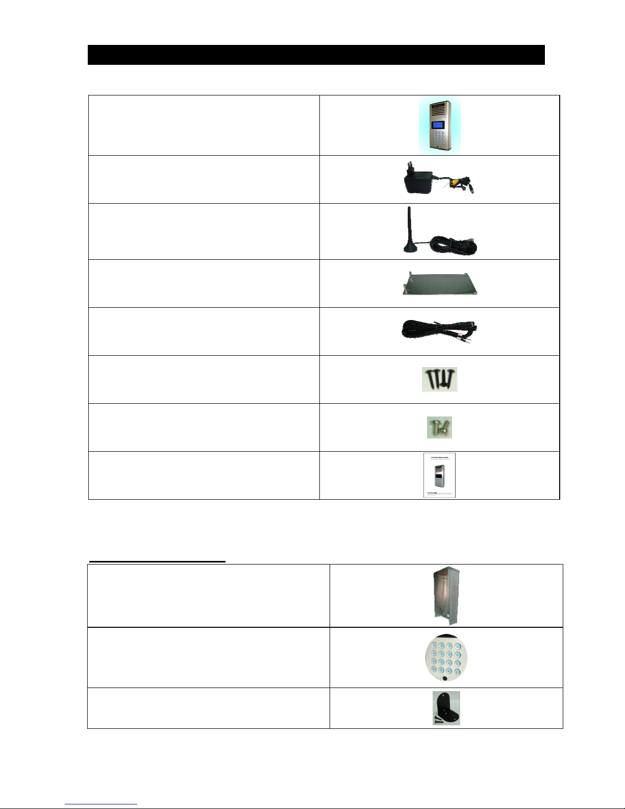
UNPACKING YOUR SYSTEM
Your GSM Door Phone system will include the followings:
1 x Door phone unit
1 x AC power adapter
1 x GSM antenna
1 x Wall mounting bracket
1 x Wire
4 x screws for mounting bracket
2 x screws for door phone
1 x User manual
Optional Accessories
Rain hood
Back light keypad
Antenna bracket
Page 5
4
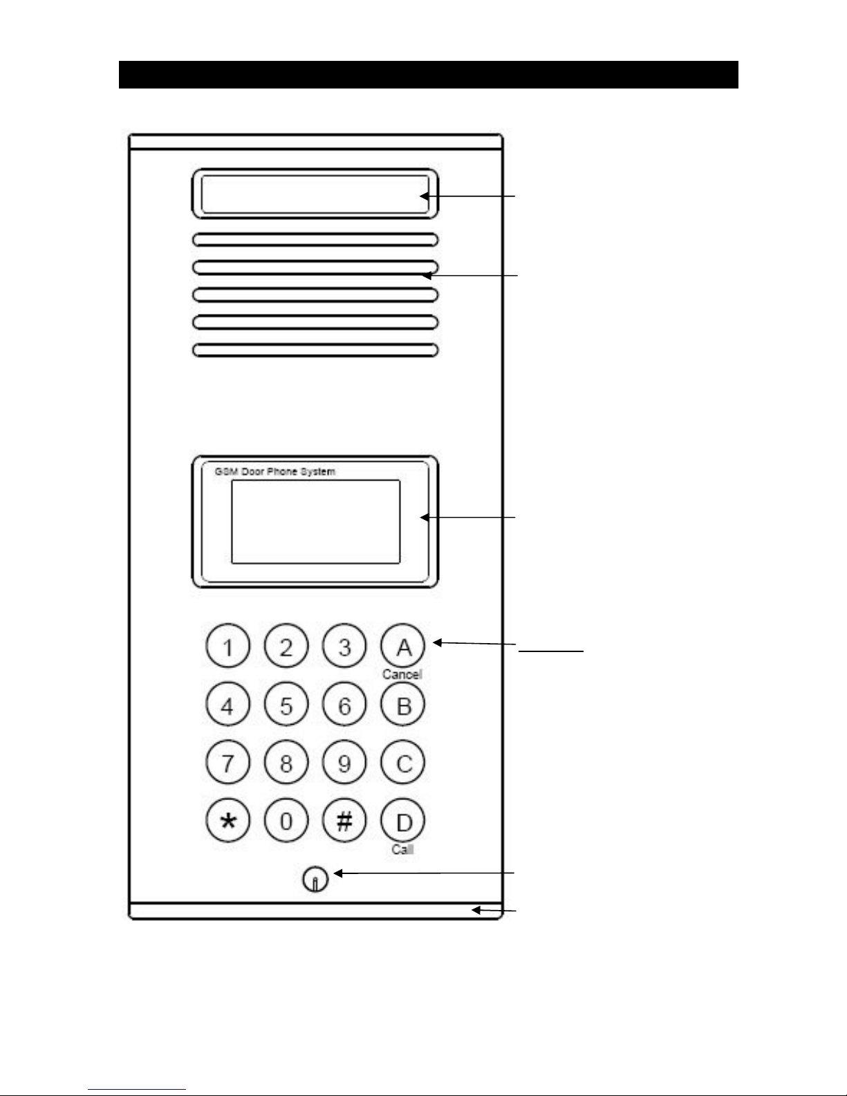
System Diagram (Front View)
Acrylic cover
Speaker
LCD display
Keypad
0~9: Number keys
A: Menu/Exit/Cancel key
B: Delete key
C: ABC/abc/123 exchange key
D: Call button
****: Volume & select up key
####: Volume & select down key
Microphone
Bottom cover
Page 6
5
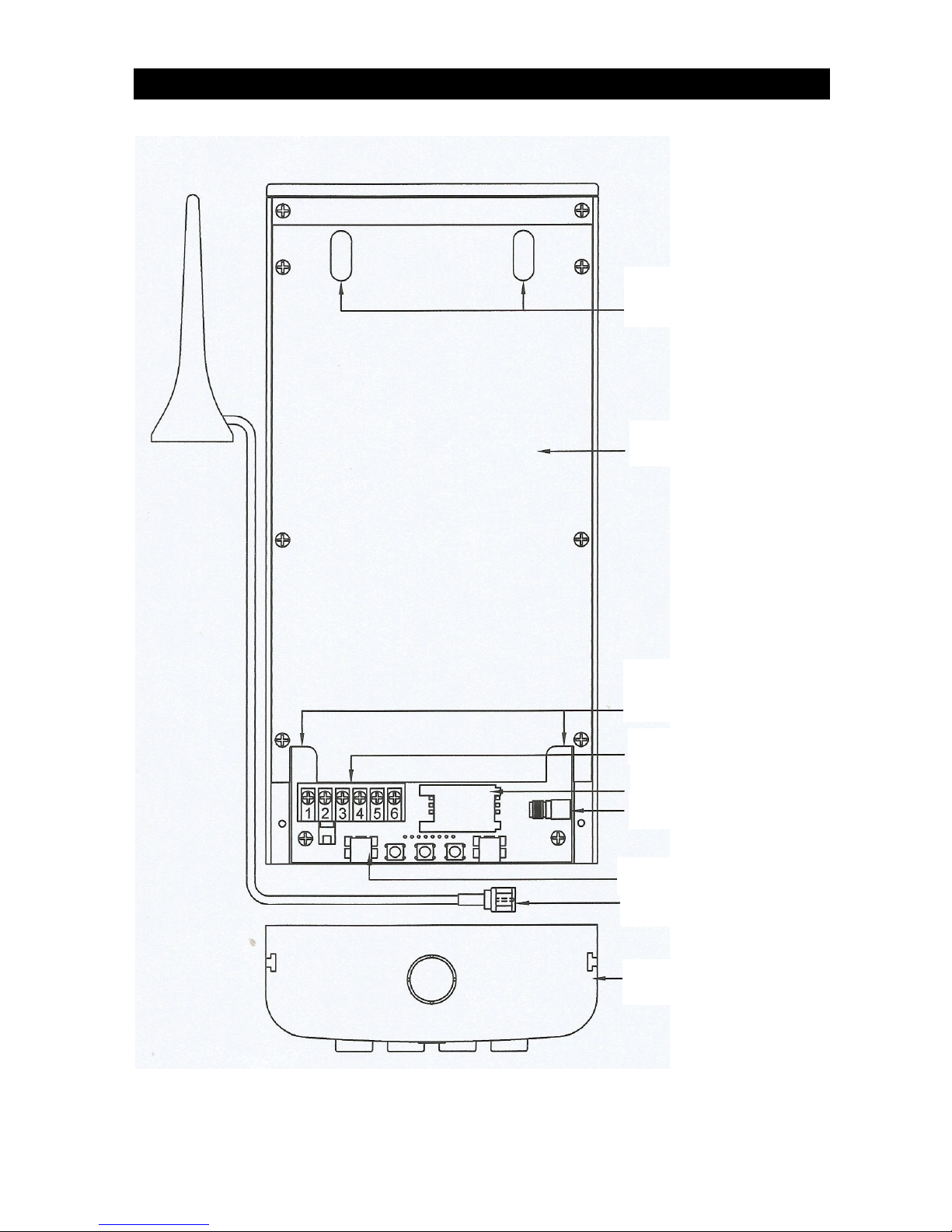
System Diagram (Back View)
Opening for connecting
wall-mount bracket
Metal back cover plate
Opening for connecting
wall-mount latch
SIM card slot
Wiring terminal
USB port
GSM antenna
Bottom cover
GSM Antenna socket
Page 7
6
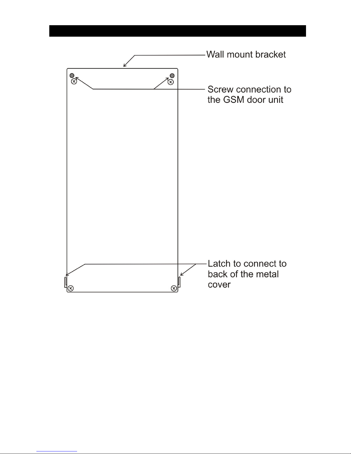
System Diagram (Wall Mounting Bracket)
Page 8
7
INSTALLATION
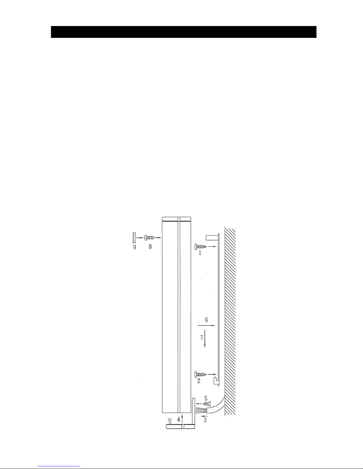
GSM Door Phone
1. Take the wall-mount bracket from the package and screw it on proper
place (as Step 1 & 2 shown below).
2. Open the bottom cover of door unit and pass the wires through the hole.
Then, refer to the “Wiring Diagram and Wiring Instruction” to connect
wires and insert the SIM card to SIM card slot (as Step 3 shown below).
Note: The GSM Door phone can not work in case there is password set on SIM
card. Please check and then release the password setting on the SIM card.
Please also delete all SMS on the SIM card.
3. Put the bottom cover back (as Step 4 shown below).
4. Place door unit on the fixed wall-mount bracket (as Step 6 & 7 shown
below).
5. Put the acrylic cover on the door unit when door unit has been screwed
(as Step 8 & 9 shown below).
Page 9

8
6. Plug the AC adapter into the AC outlet, then the door unit will go into
standby mode.
WARNING: Only use the original power adapter supplied. Using any other
adapter might damage the door unit and cause a risk of electric
shock.
Wiring Instructions
1. System Power Supply Wiring
The system power supply (adapter) AC 120V or 230V / DC 13V is provided
along with the system (please note whether it can meet local voltage
specification).
The negative wire is connected to Terminal Pin 1 and the positive wire is
connected to Terminal Pin 2.
Page 10

9
2. Install Door Lock with System Power Wiring
If the door lock power need supply from the system "Terminal Pin 2 and Pin 3
should be short and connect to the adapter positive end, "Terminal Pin 1 and
Pin 5 should be short and connect to the adapter negative end.
The lock positive wire to Terminal Pin 4 and the negative wire to Terminal Pin
5. (The system will supply 12 volts DC at 1000mA.)
3. Install Door Lock with its own Power Supply Wiring
If the door lock comes with its own power supply or requires more power than
what this unit provides, then the power should be connected as follows: Remove
the jumper wires joining Terminal Pin 2 and Terminal Pin 3. Remove the jumper
wires joining Terminal Pin 1 and Terminal Pin 5 as well. The positive wire of
the power supply is connected to Terminal Pin 3 and the negative wire to
Terminal Pin 5. The door lock’s positive wire is connected to Terminal Pin 4 and
the negative wire is to Terminal Pin 5.
4. Install Door lock 2
If Door lock 2 will use please follow below drawing to wiring, the positive wire of
the power supply is connected to Terminal Pin 6 and the negative wire to
Terminal Pin 8. The door lock 2’s positive wire is connected to Terminal Pin 7
and the negative wire is to Terminal Pin 8.
Page 11

10
OPERATION
Before operation: Please make sure the GSM Door Phone is installed
correctly. Please also study all button functions before use.
Power On/Off
Turn on the power
Insert the plug of the power adapter into the DC power jack of door unit
and the other end into an AC power outlet.
When the power is on, the system will emit a “beep” sound, show “GSM
Door Phone” and software version on screen, then show “Search
Network” for a few seconds, and then go to standby mode.
.
Turn off the power
Turn off the door unit by unplugging the power adapter from the AC power
outlet.
Dial extension number
During the period of dialing telephone number, press C key to enter *, # or
+. (Pressing C key one time is *, two times is #, three times is +. It will
be showed in cycle.)
To dial the extension number, the procedures are as listed below:
1. Dial telephone number.
2. Press C key one time and * will be showed on screen. (* = waiting for one
second, ** = waiting for 2 seconds, *** = waiting for 3 seconds, ...)
3. Dial extension number.
For example:
03726692***123 (When telephone number 037266922 is connected, the
phone will connect extension number 123 after 3 seconds.)
GSM Door Phone
Ver. 4.13E
Search Network
Enter
Flat Number
then CALL
Page 12

11
Manager Mode and Functions
Note: The unit will be time out after 5 seconds if no button is pressed.
Press A (MENU) button, and the system will show "Hello! Manager!
"Password: ______".
After entering default password "123456", press D Call button to show the
button functions as listed below:
Press any button or wait for 6 seconds, it will show:
Manager Settings
Under the Manager section, there are 4 main options: “System Setting”,
“Volume Setting”, “Door Setting” and “Calling Setting”.
Press D Call button to enter System Setting.
Change Password
Manager System Setting Change Password
Note: The Manager Password is the key to enter Programming Mode. Please
make sure to keep the Manager Password in a safe place. If you forget the Manager
Password, you’ll have to do a Master Reset which will delete your stored phone
numbers and settings.
Hello! Manager!
Password: _ _ _ _ _ _
System Setting
Volume Setting
Door Setting
Calling Setting
Cha
nge Password
Manager Phone
Talking Time
Greetings
D : Select/Save
A: Menu/Exit
B: Delete
****/####: Move Cursor
▲▲▲▲ ▼▼▼▼
Manager
Subscriber
Sub
-
Menu
Page 13

12
Under the Manager Menu option, press D Call button.
Select System Setting and press D Call button.
Select Change Password and press D Call button.
Enter new password by Number button (must be 6 digits).
Enter password again to confirm and press D Call button.
Manager Phone Number
Manager System Setting Manager Phone
Note: This will be the number that is called when the D CALL button is pressed in
standby mode.
Under the Manager Menu option, press D Call button.
Select System Setting and press D Call button.
Select Manager Phone by ****/#### key and press D Call button.
With cursor on the 1, press D Call button to enter phone number
Enter phone number with prefix and area code, then press D Call button to save.
(If you enter a number incorrectly, use the ****/#### button to move forwards or
backwards. The B (Delete) button will clear a digit you do not want.)
Press A(EXIT) button to return to previous option screen.
Set Seconds for Talking Time
Manager System Setting Talking Time
Under the Manager Menu option, press D Call button.
Select System Setting and press D Call button.
Select Talking Time and press D Call button.
Input the number for minutes you will need for the intercom to be made without
re-dial, then press D Call button to save.
Press A (Exit) button to return to previous option screen.
* Talking time: Setting from 10~180 seconds.
Change Password
New: _______
Confirm: _______
Manager Phone #
1:
Talking Time
030 Second(s)
Page 14

13
Set “Greetings”
Manager System Setting Greetings
Under the Manager Menu option, press D Call button.
Select System Setting and press D Call button.
Select Greetings and press D Call button.
Select the default 1, 2 or User setting.
Enter the Greetings: 1 or 2 screen, then select default 1 or 2, press
A(Exit) to confirm and exit.
To set the “Greetings” by user, press * or # key to start the setting.
Press C key to select ABC, abc or 123. 0 key for space.
After “Greetings” is set, press D Call button to save, press A (Exit) to exit
and return to previous option screen.
Volume Settings
Change Microphone Volume
Manager Volume Setting Mic. Volume
Note: There are 2 (High and Low) of sensitivity for the microphone volume. If the
GSM Door Phone is installed outdoors, please set the microphone level to “High”.
This may help to reduce picking up too much background noise and/or feedback
from the speaker.
Under the Manager Menu option, press D CALL button.
Select Volume Setting and press D CALL button.
Select Mic. Volume and press D CALL button.
Mic. Volume
High
Mic. Volume
Speaker Volume
Greetings: User
Press **** or #
to edit
Greetings: 1
Enter
Flat Number
then CALL
Greetings: 2
Welcome!
Page 15

14
Press ****(up)/####(Down)/D buttons to adjust volume to High or Low.
Press A (Exit) button to return to the previous option screen and the last setting
will be saved automatically.
Change Speaker Volume
Manager Volume Setting Speaker Volume
Note: There are 9 levels of speaker volume from left (lowest) to right (loudest). If the
GSM Door Phone is installed outdoors, please set the speaker level to 4 or 5. Try
not to set the speaker volume to the maximum level because it may cause feedback.
Under the Manager Menu option, press D Call button.
Select Volume Setting and press D Call button.
Select Speaker Volume and press D Call button.
Press ****/#### (Up/Down) buttons to adjust volume.
Press A (Exit) button to return to the previous option screen and the last
setting will be saved automatically.
Change Speaker Volume during Conversation
At any time during the conversation, if the caller needs to increase speaker
volume, he can press ****/#### (Up/Down) buttons to make adjustment. The
screen will show the current speaker volume and the microphone will be mute
for 1.5 seconds, then the conversation will be continued.
Speaker Volume
<-****..… ->
Page 16

15
Door Setting
Enable/Disable Door Lock Open by Password
Manager Door Setting Open by Password
Note: If your GSM Door Phone is connected with an electric door strike, you can activate the
password feature to open the door lock with a password. The default password is “123456”.
Under the Manager Menu option, press D CALL button.
Select Door Setting and press D CALL button.
Select Open by Password and press D CALL button.
Press D Call button to toggle between “Enabled” and “Disabled”.
Press A (Exit) button to return to the previous option screen and the last
setting will be saved.
Under standby mode, press the password and then press “A” to open the
door.
Caller ID Open
Manager Door Setting Caller ID Open
Note: This GSM Door Phone system will allow the user to open door by Caller ID function.
This feature is designed for easy access control.
Under the Manager Menu option, press D Call button.
Select Door Setting and press D Call button.
Select Caller ID Open and press D Call button to Enable or Disable this
function.
Press D Call button to save the function.
Press A (Exit) button to return to previous option screen.
Open by Password
Caller ID Open
Door Open Time
Door Relay Type
Open by Password
Function: Enable
Password: xxxxxx
Caller ID Open
Function: Enable
Page 17

16
Door Opening Time
Manager Door Setting Door Open Time
Note: This GSM Door Phone system will allow the user to set how long the door lock
will be opened. Sometimes, the user might need more time to reach from the door
phone unit to the locked main gate. We suggest to set enough time to allow him/her
walk in no hurry. (Setting time from 01~99 Second(s))
Under the Manager Menu option, press D button.
Select Door Setting and press D button.
Select Door Open Time and press D button.
Enter the Number of seconds from 01 to 99.
Press D button to save.
Press A (Exit) button to return to previous options screen.
Door Relay Type
Manager Door Setting Door Relay Type
Under the Manager Menu option, press D Call button.
Select Door Setting and press D Call button.
Select Door Relay Type and press D Call button.
Press ****/####(Up/Down) buttons to select “Normal Open” or Normal Close”.
Press D Call button to save the setting.
Press A (Exit) button for back to previous option screen.
Calling Setting
Set Calling Time
Manager Calling Setting Calling Time
Door Open Time
03 Second(s)
Door Relay Type
Normal Open
Page 18

17
Note: The GSM Door Phone can be set with the calling time by seconds.
Under the Manager Menu option, press D CALL button.
Select Calling Setting and press D CALL button.
Select Calling Time and press D CALL button.
Press Number button to set calling time and press D CALL button to save.
Press A (EXIT) button for back to the previous option screen.
Change the Calling by List
Manager Calling Setting Calling by List
Note: The GSM Door Phone system will call the 2nd phone number when 1st phone
number is not available when the “calling by list” is set to “ON”. To store phone
numbers, please refer to “Store Manager Phone number” section.
Under the Manager Menu option, press D CALL button.
Use ****/#### to select Calling Setting and press D CALL button.
Use ****/#### to select Calling by List and press D CALL button.
Press D button to adjust On or Off for the Calling by List function.
Press A (EXIT) button to return to previous option screen.
Set the Incoming Call
Manager Calling Setting Incoming Call
Note: The GSM Door Phone system will allow the user to set the calling by list.
Under the Manager Menu option, press D Call button.
Use ****/#### button to select Calling Setting and press D Call button to
enter.
Use ****/#### button to select Incoming Call and press D Call button .
Calling Time
Calling by List
Incoming Call
Video Call
Calling Time
25 Second(s)
Calling by List
Off
Incoming Call
Ringer : OFF
Page 19

18
Press D button to select Ringer function ON or OFF.
Press A (Exit) button to return to previous option screen.
Subscriber:
The Subscriber function supports to set up multiple tenants and enable the
user to press a subscriber number by the D Call button to connect with the
tenant. A subscriber ID # can be set from 1 to 6 digits in length. There are
maximum 750 subscribers which can have 3 phone numbers programmed for
each.
The first registered phone number will be the first number that the GSM Door
Phone will call. If the first registered number is busy or no one answers the
call, the door phone will automatically dial the second registered number.
We suggest that the first number can be the home phone number and the
second number can be a mobile phone number.
Subscriber ID Number Setup
Subscriber Enter Subscriber ID: _
→
Select Subscriber Menu option and press D Call button.
You can choose from 1 digit to 6 digits for the Subscriber ID.
Enter Subscriber ID “_____” and press D Call button.
Press 1 button and press D Call button to start input of the first tenant information.
Use ****/#### button to move cursor to “Yes” and press D Call button to confirm.
While the cursor is moved to “N” (Name) position, press D Call button, and then
you can enter the tenant’s name by 2~9 Number buttons. (Use F3 button to select
ABC or abc, 0 button = space button).
Move cursor to 1 by *
**
*/#### button and press D Call button to enter. Enter the first
phone number with area code, then press D Call button to save.
Move cursor to 2 by *
**
*/#### button and press D Call button to enter. Enter the
second phone number with area code, then press D Call button to save.
Press A (Exit) button to exit.
(Note: Follow above steps to set the other tenant’s name and phone number.)
Enter Subscriber
ID: __________
Enter Subscriber
ID: 1_______
Add? No Yes
Inh:
N ID: 1_______
N:
1:
2:
Page 20

19
Sub-Menu
Sub-Menu SMS Setting Setting by SMS
Note: The GSM Door Phone system allows the user to set function by SMS. Before
setting by SMS, the user has to ON the function of Setting by SMS. For the detail of
SMS setting, please find the list attached with the user manual.
Use ****/#### to select Sub-Menu and press D button to enter.
On SMS Setting Menu, press D button to enter.
Press D button to adjust On or Off the Setting by SMS function.
Press A (EXIT) button to return to previous option screen.
Contact a Subscriber
Under the "Welcome!" mode, enter User ID number (from 1 ~ 999999) and then
press D Call button.
If the ID exists, the system will start dialing and show “Calling…” on the screen.
When the phone is connected, the screen will show “Talking”.
If the ID does not exist, the screen will show “Incorrect!”.
If the ID exists, but there is no number assigned, the screen will show “Calling…”,
but will never connect and then time out after 3 minutes. In order to avoid this
problem, please make sure to input the phone number on each User ID.
If the dialing fails, the screen will show “No dial tone” and go back to standby
mode.
If the call is not answered within one minute, the screen will show “No answer”
and go back to standby mode.
Setting by SMS
ON
Calling- - -
Incorrect!
No dial tone!
Welcome
Candy
House
No answer!
Welcome
Candy
House
Talking- - -
Calling- - - Time’s Up!
Page 21

20
During conversation, if the other party hangs up or the line is cut, the screen will
show “No carrier” and go back to standby mode.
During conversation or while dialing, pressing A (Menu/Exit) or B (Delete/Cancel)
button will stop the conversation.
Open the Door Remotely
During conversation, the called party can press the **** button to open the door.
The door-open time can be set by user. The default setting is 3 seconds.
Go Back to Standby Screen Automatically
If the manager password has been entered and no button is pressed within 30
seconds, the screen will go back to the standby mode – “Welcome!”
If a Subscriber ID is entered and no button is pressed within 6 seconds, the
screen will go back to the standby mode.
If no button is pressed within 30 seconds under the Manager or Subscriber
option, the screen will go back to the standby mode.
SIM Card
If the SIM card is not inserted, the screen will show “SIM not Inserted” when the
system is turned on.
Call Manager
If “Manager Phone #” has been programmed, the system will directly dial this
number while the visitor presses D Call button at the standby mode.
If “Manager Phone #” is not stored, no action will be taken by pressing the D
Call button
Master Reset
The following operation will make the unit back to factory default. Please note
that this will erase all passwords, phone numbers and subscribers.
At the Standby mode, press B(C), *
**
*(UP), ****(UP), ****(UP), ####(DOWN), ####
(DOWN), ####(DOWN) and D Call buttons in sequence. It will show “Initial
System Please Wait…”, then all is back to default.
No carrier!
Welcome
Candy
House
SIM not Inserted
Page 22

21
PC Programming Function Setting
a. Install the GSM Door Phone software to PC.
b. Connect the USB cable from GSM door phone to PC.
USB port to PC
c. Then, you can start the Function Setting from PC. Please refer the
information as follows:
1. System Setting
Click [Load Default] button to reset the door phone unit to the
factory settings.
Page 23

22
Select or input the new settings and then click [Set] button to
setup the door phone unit.
2. Change Password
Click [Set] button to change the door phone with the new
password.
3. Firmware Update
Click [Open] button to select the firmware file to be updated.
Put the door phone unit into the program mode, and then and the
click [Program] button to start to update the firmware.
How to put the door phone unit into the program mode:
There are two tack switches on the PCB of the door phone unit,
press and hold the [ISP] switch first, and then press the [RESET]
switch for 2 seconds then release the [RESET] switch, keep [ISP]
switch on hold for 2 more seconds and then release the [ISP]
switch, the door phone unit enter into the program mode now.
Page 24

23
4. Subscriber Loading
Click [Open] button to select the subscriber file to be uploaded.
Click [Upload] button to start uploading the subscriber list to the
door phone unit.
Click [Download] button to start downloading the subscriber list
from the door phone unit.
Click [Save] button to save the subscriber list to the opened file.
Click [Save As] button to save the subscriber list to a new file.
Click [Add] to enter ID, Name, Phone 1, Phone 2, Phone 3, Inhibit
data and then click [OK] to add new subscriber to the subscriber
list or click [Cancel] button to abort.
Click [Edit] to change ID, Name, Phone 1, Phone 2, Phone 3,
Inhibit and then click [OK] to replace the subscriber selected or
click [Cancel] button to abort.
Click [Delete] to and then click [OK] to remove the subscriber
selected or click [Cancel] button to abort.
Page 25

24
SMS Control
Command format:
<password>#<command type>#<data1>[,<data2>,<data3>,<data…>]#
Description Command SMS Response Remarks Example
1 Default
Password
123456#01#12
3456#
Reset to Default
Password
123456
default=123456 123456#01#123456#
2 Change
Password
<password>#02
#<new
password>#
New Password
<new password>
000000~999999 123456#02#266922#
5 Set
Microphone
Volume
<password>#05
#<microphone
volume>#
Microphone
Volume
<microphone
volume>
<microphone
volume>=1~9
123456#05#4#
6 Get
Microphone
Volume
<password>#06
#
Microphone
Volume
<microphone
volume>
<microphone
volume>=1~9
123456#06#
7 Set Speaker
Volume
<password>#07
#<speaker
volume>#
Speaker Volume
<speaker
volume>
<speaker
volume>=1~9
123456#07#4#
8 Get Speaker
Volume
<password>#08
#
Speaker Volume
<speaker
volume>
<speaker
volume>=1~9
123456#08#
9 Set Talking
Time
<password>#09
#<time>#
Talking Time
<time> Seconds
<time>10~180
seconds
123456#09#30#
10 Get Talking
Time
<password>#10
#<time>#
Talking Time
<time> Seconds
<time>=10~180
seconds
123456#10#
11 Get Firmware
Version
<password>#11
#
Firmware Version
<version>
123456#11#
12 Set Open
Door by
Password
<password>#12
#<function>#<o
pen door
password>#
Open Door by
Password is
Enabled(Disable
d)<open door
password>
<function>
=1(enable);
=0(disable)
<open door
password>=
000000~999999
123456#12#1#26692
2#
13 Set Door
Open Time
<password>#13
#<dooropen
time>#
Door Open Time
<door open time>
<door open time>
=2~99seconds
123456#13#3#
14 Set Door
Relay Type
<password>#14
#<door relay
type>#
Door Relay Type
is Normal
Open(or Close)
<door relay
type>:
0=normal open
1=normal close
123456#14#1#
15 Set Calling
Time
<password>#15
#<calling
time>#
Calling Time
<calling time>
<calling time>
=25~99seconds
123456#15#30#
Page 26

25
Description Command SMS Response Remarks Example
16
Set Calling by
List
<password>#16
#<function>#
Calling List is
Enabled( or
Disabled)
<function>:
0=disable
1=enable
123456#16#1#
18 Set Greetings <password>#18
#<greeting
option >[,
<line1>,<line2>
,<line3>]#
Greetings:
Enter Flat
Number then Call
(or Welcome!)(or
line1__line2__lin
e3)
<greeting
option>:
1=Enter Flat
Number then
Call
2=Welcome!
3=user defined
<line1>: 16 char
<line2>: 16 char
<line3>: 16 char
123456#18#1#
123456#18#2#
(use line1,line2,line3)
123456#18#3,
Press, CALL,
for Assistant#
(use line1)
123456#18#3, Press
CALL key,,#
20 Add
Subscriber
<password>#20
#<id>,<name>,
<phone1>)[,<ph
one2>][,<phone
3>],<inhibit>#
Subscriber
Added,
<id>,<name>,<p
hone1>[,<phone
2>][,<phone3>],N
ormal( or Inhibit)
or
Subscriber NOT
Added,<id> –
Memory Full!
or
Subscriber NOT
Added,<id>– ID
existed!
1-phone number
model:
16 digits
maximum
2-phone number
model:
20 digits
maximum
3-phone number
model:
20 digits
maximum
1-phone number:
123456#20#1,Peter,0
37266922,0#
2-phone number:
123456#20#1,Peter,0
37266922,0372669
23,0#
3-phone number:
123456#20#1,Peter,0
37266922,0372669
23,037266924,0#
21 Change
Subscriber
<password>#21
#<id>,<name>,
<phone1>)[,<ph
one2>][,<phone
3>],<inhibit>#
Subscriber
Changed,
<id>,<name>,<p
hone1>[,<phone
2>][,<phone3>],N
ormal( or Inhibit)
Subscriber NOT
Changed,<id> –
ID is not existed!
1-phone number
model:
16 digits
maximum
2-phone number
model:
20 digits
maximum
3-phone number
model:
20 digits
maximum
1-phone number:
123456#21#1,Peter,0
37266922,0#
2-phone number:
123456#21#1,Peter,0
37266922,0372669
23,0#
3-phone number:
123456#21#1,Peter,0
37266922,0372669
23,037266924,0#
Page 27

26
Description Command SMS Response Remarks Example
22 Delete
Subscriber
<password>#22
#<id>#
Subscriber
Deleted,
<id>,<name>,<p
hone1>[,<phone
2>],Normal( or
Inhibit)
Subscriber NOT
Deleted,<id> –
ID
is not existed!
123456#22#1#
23 Inquire
Subscriber
<password>#23
#<id>#
Subscriber
Inquired,
<id>,<name>,<p
hone1>[,<phone
2>],Normal( or
Inhibit)
Subscriber
Inquired,<id> –
ID is not existed!
123456#23#1#
35 Set Caller ID
Open function
<password>#35
#<function>#
Caller ID Open
Door: Disabled
Caller ID Open
Door: Enabled
function:
0=Disable
1=Enable
123456#35#0#
123456#35#1#
36 Set Incoming
Ringer
<password>#36
#<ringer>#
Incoming Call
Ringer: OFF
Incoming Call
Ringer: ON
<ringer>:
0=OFF
1=ON
123456#36#0#
123456#36#1#
37 Set IR Lux
Level
<password>#37
#<level>#
IR Lux Level: 5 <level>:0~13
123456#37#5#
123456#37#10#
38 Set IR Delay
Off Time
<password>#38
#<time>#
IR Delay Off
Time: 5
<time>:0~250 123456#38#5#
123456#38#15#
123456#38#120#
40 Set SD Full
Alert
<password>#40
#<option>#
SD Memory Full
Alert: OFF
SD Memory Full
Alert: SMS
SD Memory Full
Alert: Beeping
<option>:
0=OFF
1=SMS
2=Beeping
123456#40#0#
123456#40#1#
123456#40#2#
41 Set
Video Call
Function
<password>#41
#<function>#
Video Call: OFF
Video Call: ON
<function>:
0=OFF
1=ON
123456#41#0#
123456#41#1#
42 Set
Recording
Function
<password>#42
#<function>#
Recording: OFF
Recording: ON
<function>:
0=OFF
1=ON
123456#42#0#
123456#42#1#
43 Set Video
System
<password>#43
#<function>#
Video System:
NTSC
Video System:
PAL
<function>:
0=NTSC
1=PAL
123456#43#0#
123456#43#1#
Page 28

27
Description Command SMS Response Remarks Example
44 Open Door <password>#44
#<door>#
Door 1 is opened
Door 2 is opened
<door>
1= door 1
2= door 2
123456#44#1#
123456#44#2#
45 Set Clock <password>#45
#<date,time>#
Clock:
14/11/13,15:32
<date,time>
date=YY/MM/DD
time=hh:mm
123456#45#14/11/13
,15:32#
46 Get Clock <password>#46
#
Clock:
14/11/13,15:32
123456#46#
SMS responses messages of GSM Door phone:
Wrong Data Format
Wrong Command
Wrong Password
Invalid Password
Invalid Phone Number
Unknown Message
* This document is subject to change without notice.
 Loading...