

Page 1

* PLEASE READ CAREFULLY BEFORE USING.
CSW5007Q
MULTI CAMERA CONTROLLER FOR
OBSERVATION MONITOR
(MULTI PLE D ISPLAY MOD E)
A
A
1C
1C
C
C
A
A
2
2
C
C
A
A
3
3
A
A
A
A
V
V
-
-
O
O
U
U
V
V
T
T
I
I
R
R
- i
- i
rc
rc
e v
e v
e
e
e
e
r
C
o
n
C
C
A
A
4
4
D
D
C
C
1 V
1 V
r
A
A
A
A
V
V
-
t
r
o
l
B
o
x
P
P
O
O
I
I
W
W
P
P
E
E
UNT
UNT
0
0
R
R
~
~
3
3
2
2
V
V
-
IN
IN
V
V
Do c.Rev ( 20 07/ 05/07 )Do c.Rev ( 20 07/ 05/07 )
* De si gn a nd S pe ci fi ca ti on s ar e su bj ec t to c ha ng e wi th ou t no ti ce .* De si gn a nd S pe ci fi ca ti on s ar e su bj ec t to c ha ng e wi th ou t no ti ce .
Page 2
Owner's Record
The model and serial numbers are located at the rear.
Record the serial number in the space provided below.
Refer to these numbers whenever you call upon your dealer regarding this product.
Model No.:
Serial No.:
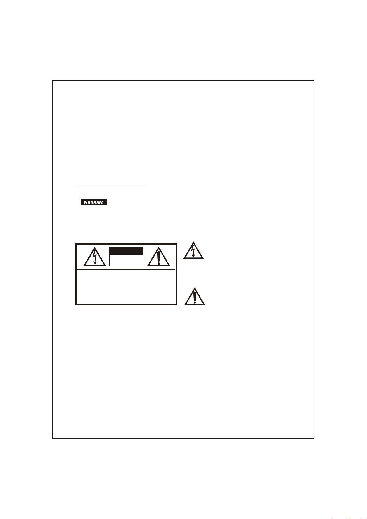
To prevent fire or shock hazard,do not expose the unit to rainor moisture.
To avoid electric shock, do not open the cabinet. Refer servicing to qualified personnel only.
This symbol is intended to alert the
user to the presence of uninsulated
CAUTION
RISK OF ELECTRIC SHOCK
RISK OF ELECTRIC SHOCK
DO NOT OPEN
DO NOT OPEN
CAUTION: TO REDUCE THE RISK OF ELECTRIC SHOCK,
DO NOT REMOVE COVER (OR BACK).
NO USER-SERVICEABLE PARTS INSIDE.
REFER SERVICING TO QUALIFIED SERVICE PERSONNEL.
"dangerous voltage" within the product's enclosure that may be of sufficient magnitude to constitute risk of
electric shock to persons.
This symbol is intended to alert the
user to the presence of important
operating and maintenance (servicing)
instructions in the literature accompanying the appliance.
You are cautioned that any changes or modifications not express approved in this manual could void
your authority to operate this equipment.
2
Page 3

INDEX
FEATURES ----------------------------------------------------------------------- 4
PRECAUTIONS ----------------------------------------------------------------- 5
SYSTEM CONNECTIONS---------------------------------------------------- 6
INSTALLATION ----- ------------------------------------------------------------ 7
OPERATIONS -------------------------------------------------------------------- 8~12
SPECIFICATIONS --------------------------------------------------------------- 13
3
Page 4

FEATURES
CSW5007Q is designed to be compatible with most voyager
observation monitors and cameras.
Input Vo ltage DC 10V ~ D C 32V
NTSC / PA L Compatibili ty
4 Camera Inputs / 1 AV In put / 1AV Outpu t
Multipl e Display Mode (Single , Spli t, Tripl e, Qua d)
Automat ic Picture Dis play (5 Trigge ring fun ction s)
Auto Sca nning functio n
ON Screen D isplay Informa tion
4
Page 5

PRECAUTIONS
Sa fe ty
- Use only DC 10V to 32V.
- In case that dust or liquid was soaked into the case, please turn off power and
consult an experienced technician before using.
- Install in a well ventilated area.
In stallation
- Do not install the unit in an extremely hot or humid place
(radiator, air duct, etc.) or in a place subject to direct sunlight, excessive dust,
mechanical vibration or shock.
5
Page 6

MO NITO R
(N ot su ppl ied )
RCA CA BLE
(s upp lie d)
RCA plug or jack (A/V)
Remote con trol sen sor
RCA plu g (A /V)
AV-OUTAV-OUT
IR-receiverIR-receiver
VV AA V V A A
AV-INAV-IN
CS W50 07Q
CO NTR OL B OX
Control Box
POWER
POWER
INPUT
INPUT
DC10V~32V
CA3CA3
CA1CA1 CA2CA2
WIRE COLOR DESCRIPTION
REF
1 RED POW ER IN + 12VDC
1 RED POW ER IN + 12VDC
2 BLU E CAMERA /TRIG GER 1
2 BLU E CAMERA /TRIG GER 1
3 BRO WN CAM ERA/T RIGGE R 2
3 BRO WN CAM ERA/T RIGGE R 2
4 YEL LOW SPLI T SCRE EN TRIG GER
4 YEL LOW SPLI T SCRE EN TRIG GER
5 BLA CK GRO UND-1 2VDC
5 BLA CK GRO UND-1 2VDC
6 ORA NGE CA MERA/ TRIGG ER 4
6 ORA NGE CA MERA/ TRIGG ER 4
7 GRE EN CAM ERA/T RIGGE R 3
7 GRE EN CAM ERA/T RIGGE R 3
8 PUR PLE* MON ITOR TR IGGER OUT
8 PUR PLE* MON ITOR TR IGGER OUT
DC10V~32V
CA4CA4
* Thi s wire c onnec ts to rev erse wi re inpu t (trig ger 'ON ') for mo nitor d ispla y.
Is in tende d for tri gger on ly, not fo r main p ower su pply.
6
Page 7

INSTALLATION
Install the control bo x on a place whi ch can ho ld
more wei ght than 5 Kgs ( 11 lb).
Fasten t he control box with the provi ded scre ws as
the draw ings below.
Mounting on the floor, console, etc.
Jack Bracket
Fasten the jack bracket with provided screws after
connecting the cameras.
Audio Outpu t
Vid eo Ou tpu t
Sensor Signal
Input
Audio Input
Vid eo In put
Camera Input
CA 1
CA 2
CA 3
CA 4
Power / Trigger Inp ut
7
Page 8

OPERATION
Remote C ontrol
11
POWER button
- Press POWER button to turn
the control box on or off.
4
1
5
3
2
6
44
CH.SELE button
- Press CH.SELE button to select the display image.
Sequential press shows the image of each camera in turn below.
( CAM1 CAM2 CAM3 CAM4 AUX SPLIT2 SPLIT3 SPLIT4 )
* OSD indicates which image is displayed on the screen.
* When the trigger signal is activated,
the selected source's image will be
displayed on the monitor screen
automatically. (Please refer to
TRIGGER MODE in SETUP MENU
for further information)
22
- / + button
- Press - / + button to adjust BRIGHT or
CONTRAST level.
- Press - / + button to select the content
of the selected line in each sub menu.
33
UP / DOWN button
- Press UP / DOWN button to adjust
TILT (PAN) camera position upward or
downward.
(Available only when TILT (PAN) camera
Is connected to CA1, CA2, or CA3 input)
- Press UP/ DOWN button to move the
cursor up or down in SETUP MENU
and each sub menu.
- Press CH.SELE button to select the items, in which the cursor is in menu.
- Press CH.SELE button to start or stop scanning each display mode sequentially.
Available only when AUTO SCAN in menu is ON.
55
CA1, CA2, CA3, CA4/AV button
- Press CA1, CA2 or CA3 button to select each camera.
- Press CA4 / AV button to select CA4 and press again to select any AV device
connected.
8
Page 9

OPERATION
66
MENU button
- Press MENU button for less than 0.5 second to go to BRIGHT or
CONTRAST mode.
Use - / + button to adjust BRIGHT or CONTRAST level.
( BRIGHT CONTRAST BRIGHT... )
- Press MENU button for over 1 second to enter into SETUP MENU.
Use UP / DOWN to move up and down and use - / + button to move left and
right in SETUP MENU and each sub menu.
- Press MENU button to go back to the previous menu when in SETUP MENU or
each sub menu.
* SELECTABLE OSD MENU DISAPPEARS WITHIN 10 SECONDS IF THERE IS
NO NEW INPUT SIGN.
MENU
SETUP MENU
-- SETU P MEN U --
1. CAMERA SOR T
2. NORMAL / MI RRO R
3. TRIGGER MO DE
4. SCREEN SPL IT
5. CAMERA NAM E
6. SCALE MODE
7. AUTO SC AN
8. AD VANCED ME NU
1. CAMERA SORT
- Move cursor up or down by pressing
UP / DOWN button
CAM 1: [NOR MAL,S HUTTE R, PAN/T ILT]
- Press CH.SELE button to select CAM1, CAM2
CAM 2: [NOR MAL,S HUTTE R, PAN/T ILT]
or CAM3
CAM 3: [NOR MAL,S HUTTE R, PAN/T ILT]
- Select each camera sort by pressing - / + button
in the selected camera
- Exit from the menu by pressing MENU button
CAUTION!
* CAM4 is only available with NORMAL CAMERA.
* Wrong camera connections may cause any malfunction.
9
Page 10

OPERATION
2. NORMAL / MIRROR
CAM 1: [NOR MAL, MI RROR]
CAM 2: [NOR MAL, MI RROR]
CAM 3: [NOR MAL, MI RROR]
CAM 4: [NOR MAL, MI RROR]
3. TRIGGER MODE
TRI GGER SO URCE
TIR GGER DE LAY
TRIGGER SOURCE
TRIGGER1:[CAM1,CAM2,CAM3,CAM4,AUX,SPLIT2,SPLIT3,SPLIT4]
TRIGGER2:[CAM1,CAM2,CAM3,CAM4,AUX,SPLIT2,SPLIT3,SPLIT4]
TRIGGER3:[CAM1,CAM2,CAM3,CAM4,AUX,SPLIT2,SPLIT3,SPLIT4]
TRIGGER4:[CAM1,CAM2,CAM3,CAM4,AUX,SPLIT2,SPLIT3,SPLIT4]
TRIGGER5:[CAM1,CAM2,CAM3,CAM4,AUX,SPLIT2,SPLIT3,SPLIT4]
* When the trigger signal is activated, the selected source's image is displayed on
screen.
* TRIGGER PRIORITY : TRIGGER1 > TRIGGER2 > TRIGGER3 >
TRIGGER4 > TRIGGER5
TRIGGER DELAY
TRI GGER1 : [ 0 ~20 sec ]
TRI GGER2 : [ 0 ~20 sec ]
TRI GGER3 : [ 0 ~20 sec ]
TRI GGER4 : [ 0 ~20 sec ]
TRI GGER5 : [ 0 ~20 sec ]
- Move cursor up or down by pressing
UP / DOWN button
- Press CH.SELE button to select CAM1, CAM2,
CAM3 or CAM4
- Select normal or mirror by pressing - / + button
in the selected camera
- Exit from the menu by pressing MENU button
- Move cursor up or down by pressing
UP / DOWN button
- Press CH.SELE button to select TRIGGER
SOURCE or TRIGGER DELAY menu
- Move cursor up or down by pressing
UP / DOWN button
- Press CH.SELE button to select TRIGGER1, 2,
3, 4 or 5
- Select CAM1, CAM2, CAM3, CAM4, AUX,
SPLIT2, SPLIT3 or SPLIT4 by pressing
- / + button in the selected trigger
- Exit from the menu by pressing MENU button
- Move cursor up or down by pressing
UP / DOWN button
- Press CH.SELE button to select TRIGGER 1, 2,
3, 4 or 5
- Determine each trigger delay time by adjusting
- / + button
- Exit from the menu by pressing MENU button
10
Page 11

OPERATION
4. SCREEN SPLIT
SPL IT 2
SPL IT 3
SPL IT 4
SPLIT2
SOURCE1: [CAM1,CAM2,CAM3,CAM4]
SOURCE2: [CAM1,CAM2,CAM3,CAM4]
AUDIO : [CAM1,CAM2,CAM3,CAM4]
SPLIT3
SOURCE1:[CAM1,CAM2,CAM3,CAM4]
SOURCE2:[CAM1,CAM2,CAM3,CAM4]
SOURCE3:[CAM1,CAM2,CAM3,CAM4,OFF]
AUDIO :[CAM1,CAM2,CAM3,CAM4]
SPLIT4
SOURCE1:[CAM1,CAM2,CAM3,CAM4]
SOURCE2:[CAM1,CAM2,CAM3,CAM4]
SOURCE3:[CAM1,CAM2,CAM3,CAM4,OFF]
SOURCE4:[CAM1,CAM2,CAM3,CAM4,OFF]
AUDIO :[CAM1,CAM2,CAM3,CAM4]
- Move cursor up or down by pressing
UP / DOWN button
- Press CH.SELE button to select SPLIT2,
SPLIT3
or SPLIT4
- Exit from the menu by pressing MENU button
- Move cursor up or down by pressing
UP / DOWN button
- Press CH.SELE button to select SOURCE1,
SOURCE2 or AUDIO
- Select CAM1, CAM2, CAM3 or CAM4 by
pressing - / + button
- Exit from the menu by pressing MENU button
- Set up SPLIT3 or SPLIT4 in the same way with
SPLIT2 above
* Multiple images can be displayed. (DUAL,
TRIPLE AND QUAD IMAGES)
* Only one audio can be chosen in each SPLIT
mode.
5. CAMERA NAME
- Move cursor up or down by pressing
CAM1: [CAM1 ]
CAM2: [CAM2 ]
CAM3: [CAM3 ]
CAM4: [CAM4 ]
UP / DOWN button
- Press CH.SELE button to select CAM1, CAM2,
CAM3 or CAM4
- Select letter by pressing - / + button sequentially
- Press CH.SELE button to move to the next letter
- Exit from the menu by pressing MENU button
* Each camera can be named and the camera names are displayed on screen.
11
Page 12

OPERATION
6. SCALE MODE
CAM 1: [OFF, SCA LE1 , SCAL E2]
CAM 2: [OFF, SCA LE1 , SCAL E2]
CAM 3: [OFF, SCA LE1 , SCAL E2]
CAM 4: [OFF, SCA LE1 , SCAL E2]
SCA LE 1
SCA LE 2
* The distance marker of SCALE1 and SCALE2 can be adjusted.
* When the trigger signal is activated, the selected scale is displayed on screen.
7. AUTO SCAN
AUT O SCAN: [ ON, OFF ]
SCA N CAM1: [ 0 ~ 20 sec]
SCA N CAM2: [ 0 ~ 20 sec]
SCA N CAM3: [ 0 ~ 20 sec]
SCA N CAM4: [ 0 ~ 20 sec]
SCA N SPLIT 2: [0 ~ 20 se c]
SCA N SPLIT 3: [0 ~ 20 se c]
SCA N SPLIT 4: [0 ~ 20 se c]
8. ADVANCED MENU
NTS C MODE , PAL M ODE
AUT O POWE R : [ON , OFF]
- Move cursor up or down by pressing
UP / DOWN button
- Press CH.SELE button to select CAM1, CAM2,
CAM3, CAM4, SCALE1 or SCALE2
- Select scale OFF, SCALE1 or SCALE2 by
pressing - / + button in each camera
- Exit from the menu by pressing MENU button
- Move cursor up or down by pressing
UP / DOWN button
- Press CH.SELE button to select one of AUTO
SCAN, SCAN CAM1~4, AUX, SPLIT2~4
- Exit from the menu by pressing MENU button
- Set up the scanning time of each SCAN mode
by pressing - / + button if you select ON in
AUTO SCAN
- Select NTSC or PAL by pressing - / + button to
select the right video mode
- Select AUTO POWER ON or OFF by pressing
- / + button to select the right operation.
* When "AUTO POWER ON" is selected, the
unit is powered on automatically without using
remote controller.
* When "AUTO POWER OFF" is selected, the
unit is powered on by using remote controller.
- Exit from the menu by pressing MENU button
12
Page 13

SPECIFICATIONS
CS W5007Q
Power input ......................
Power cons. .......................
Video system ......................
Camera input (4 CH) .............
A/V output (1 CH) .................
RCA, Audio signal, 150mV RMS, 47K.
A/V input (1 CH) .....................
RCA, Audio signal, 150mV RMS, 47K.
Operating temp. ..................
Storage temp. .....................
Ambient condition .................
Vibration .............................
Dimension ...........................
6.06 (W) X 4.13 (D) X 1.10 (H) inch
Weight .................................
Supplied acc'y .....................
Mount Screws (1)
Bracket Jack (2)
Remote control (1)
Sensor for remote control (1)
Din to voyager Adapter cable
DC 10V~32V
Max. 24 Watt
NTSC or PAL
Mini DIN 4, 1 Vp-p 72
RCA, Composite video signal, 1 Vp-p 72
Composite video signal, 1 Vp-p 72
RCA,
-10 C ~ +50 C ( 14 F ~ 122 F)
-25 C ~ +80 C (-13 F ~ 176 F)
Indoor use only
5.5 G
154 (W) X 105 (D) X 28 (H) mm
Approx. 0.5 Kg
Power cord 2 M
RCA cable
(1)
(1)
(4)
* Design and specifications are subject to change without notice.
13
Page 14

Print ed in Kor ea Print ed in Kor ea
 Loading...