

Page 1
User Manual
CL-2200XP/V2
&
CL-2200XP/PBX
900 MHz LONG-RANGE CORDLESS PHONE SYSTEM
Page 2

TABLE OF CONTENTS
Introduction
Welcome……………………………………………………………………………………………………..5
Important Safety Information………………………………………………………………………………5
Unpacking Your System………………………………………………………………………………..6 - 7
Component Names and Functions
Base Unit – Desk Mount (CL-2200XP/V2)……………………………………………………………….8
Base Unit – Wall Mount (CL-2200XP/PBX)……………………………………………………………..9
Portable Handset…………………………………………………………………………………………..10
Portable Handset Charger Stand………………………………………………………………………...11
Remote Station……………………………………………………………………………………………..12
Installation
Base Unit……………………………………………………………………………………………………13
Portable Handset…………………………………………………………………………………………..14
Charger Stand………………………………………………………………………………………...14 - 15
Batteries…………………………………………………………………………………………………….15
Remote Station (optional)…………………………………………………………………………………16
Basic Operation
Turning Your Phone On/Off………………………………………………………………………………17
On Base Unit
On Portable Handset
Tone or Pulse Dialing………………………………………………………………………………..17 - 19
Tone
Pulse
Placing A Call………………………………………………………………………………………………19
Cellular Dial Mode
Normal Dial Mode
Answering A Call…………………………………………………………………………………………..20
Redialing Numbers………………………………………………………………………………………..21
Cellular Dial Mode
Normal Dial Mode
Advanced Operations & Features
Answering Options (Portable Handset Only)………………………………………………………22 - 23
Auto Answer
Press “OK” Key Or Press Any Key To Answer A Call
Vibration
Audio Volume (Base Unit & Portable Handset)…………………………………………………………24
Microphone
Speaker
Battery Low Alert (Portable Handset Only)……………………………………………………………..24
Button Confirmation Tone………………………………………………………………………………...25
Call Transfer (Base Unit & Portable Handset)…………………………………………………….26 - 26
Direct Transfer
Transfer After Talking to One Party
2
Page 3

Channels………………………………………………………………………………………………26 - 27
Base Unit
Grouping
Set Number of Available Channels
Portable Handset
Grouping
Set Number of Available Channels
Channel Scan For Free Channel (Portable Handset Only)…………………………………………...28
Dialing………………………………………………………………………………………………….28 - 30
Call Restriction (Call Barr)
Base Unit
Portable Handset
Flash Time (Base Unit Only)
Pause Time (Base Unit Only)
Energy Saving Feature (Portable Handset Only)…………………………………………………30 - 31
Group Paging (Base Unit & Portable Handset)………………………………………………………...31
ID Exchange (Base Unit Only)……………………………………………………………………...31 - 32
Intercom (Base Unit & Portable Handset)………………………………………………………………32
Keypad Backlight (Portable Handset Only)……………………………………………………….32 - 33
Out of Range Beep (Portable Handset Only)…………………………………………………………..33
Phone Book………………………………………………………………………………………………..34
Base Unit
Portable Handset
Power Level (Base Unit & Portable Handset)…………………………………………………………..35
Ringer…………………………………………………………………………………………………35 - 37
Base Unit
Ringer Melody
Volume Setting
Portable Handset
Ringer Melody
Volume Setting
Security……………………………………………………………………………………………..….37 - 41
Base Unit
Set Password Feature On/Off
Set Password
Set Security Code
Portable Handset
Set Password Feature On/Off
Set Password
Set Security Code
Key Lock
Speed Dialing………………………………………………………………………………………..41 - 42
Storing Phone Numbers in Memory
From The Base Unit
From The Portable Handset
Dialing a Stored Number
From The Base Unit
From The Portable Handset
Talk Time Control……………………………………………………………………………………42 - 43
Base Unit
Portable Handset
Voice Scramble (Portable Handset Only)……………………………………………………………….43
3
Page 4

Messaging
Answering Machine…………………………………………………………………………………..44 - 47
Set Number of Rings
Recording Outgoing Message
Listening To Outgoing Messages
Listening To Incoming Messages
Deleting Messages
Turning On/Off
Auto Voice Attendant…………………………………………………………………………………47 - 49
Turning On/Off
Recording Your Messages
Memo Message……………………………………………………………………………………………49
Multiple Systems
Numbering Handsets………………………………………………………………………………………50
Ring One Or All Portable Handsets…………………………………………………………………50 - 51
Set Line Number (CO#)………………………………………………………………………………51 - 52
Base Unit
Portable Handset
Placing A Phone Call………………………………………………………………………………………53
Intercom………………………………………………………………………………………………..53 - 54
Specifications………………………………………………………………………………….55
Troubleshooting……………………………………………………………………………….55
4
Page 5

INTRODUCTION
INTRODUCTION - Welcome
Thank you for purchasing a Voyager Long-Range wireless phone system. To ensure that you optimize the full capabilities
of this product, please read this user’s manual before proceeding. Be sure to keep this manual for future reference in
case any problems or questions should arise. We hope you enjoy your new Voyager wireless phone system.
INTRODUCTION - Important Safety Information
When using your telephone equipment, basic safety precautions should always be followed to reduce the risk of fire,
electric shock and personal injury. Please read the following before using your equipment:
1. Read and follow all instructions carefully.
2. Follow all warnings and instructions on the product.
3. Unplug the product from the host telephone equipment before cleaning. Do not use liquid cleaners or aerosol
cleaners. Use a damp cloth for cleaning.
4. Do not use this product near water.
5. Do not place this product on top of a metal surface. Do not place this product on an unstable cart, stand or
table.
6. Do not allow anything to rest on the power cords. Do not place this product in a location where the cords can
be stepped on or where someone can trip over them.
7. Do not use this product near an area where there is a potential of gas leaks or near any fumes that can be
explosive. If you notice that the equipment is being used in such a hazardous area, report this condition on a
telephone that is located in a safe location.
8. Do not place this equipment near or over a radiator or any other heat source.
9. Use ONLY the power adapter supplied with the system.
10. Do not overload the wall outlet or power cord where the power adapter is installed. This can result in fire or
electric shock.
11. This equipment is to be opened by ONLY a qualified serviceperson. There are no user serviceable parts
inside. Opening this equipment may expose you to dangerous voltage and other risks. Incorrect reassembly of
this equipment may result in electric shock.
12. Avoid spilling liquid on this equipment and do not insert any objects through the ventilation slots.
13. Avoid using this equipment during an electrical storm. There is a remote risk of electrical shock from lightning.
14. Do not use this equipment other than for its purpose intended by the manufacturer. Use ONLY the equipment
provided by the manufacturer.
15. Do not break open the batteries and do not dispose of them in fire. Dispose of batteries safely or contact your
local recycling center. Batteries contain corrosive materials that are dangerous to you and to the environment.
5
Page 6

INTRODUCTION - Unpacking Your System
Your system will include the following equipment:
CL-2200XP/Super
• 1 base unit
• 1 portable handset
• 1 standard antenna for the portable handset
• 1 short antenna for the portable handset
• 1 standard antenna for the base unit
• 1 desktop charger with power adapter
• 1 battery pack
• 1 user’s manual
CL-2200XP/Ultra
• 1 base unit with a corded handset
• 1 portable handset
• 1 standard antenna for the portable handset
• 1 short antenna for the portable handset
• 1 standard antenna for the base unit
• 1 desktop charger with power adapter
• 2 battery packs
• 1 leather case for the portable handset
• 1 user’s manual
CL-2200XP/PBX
• 1 base unit
• 1 portable handset
• 1 standard antenna for the portable handset
• 1 short antenna for the portable handset
• 1 standard antenna for the base unit
• 1 desktop charger with power adapter
• 1 battery pack
• 1 user’s manual
6
Page 7
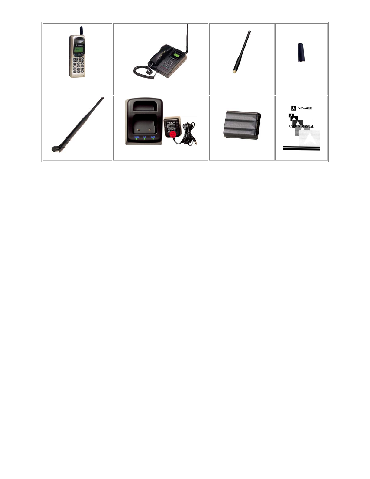
CL-2200XP-H
Handset
CL-2200XP-B
Base Unit
Short Handset
Standard Handset
Antenna
Antenna
User's Manual
Base Unit Antenna
Desktop Charger
with Power adapter
Battery Pack
7
Page 8
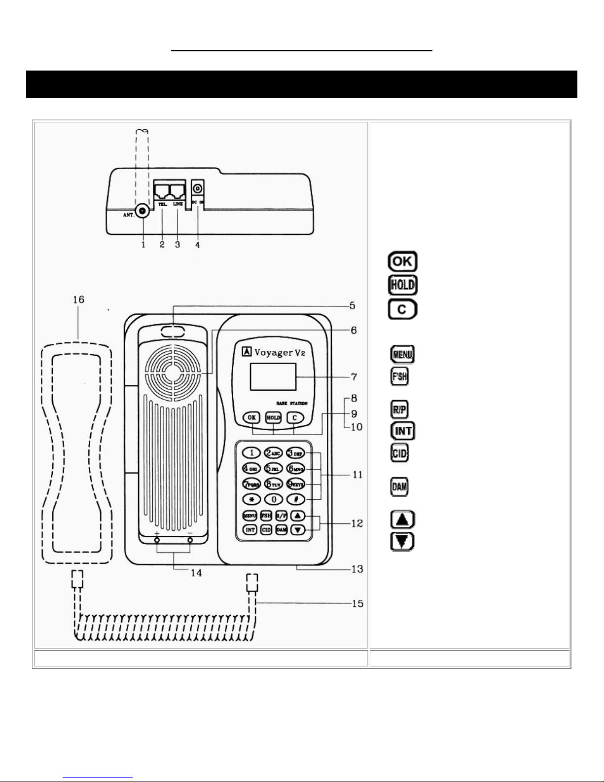
COMPONENT NAMES AND FUNCTIONS
Base Unit – Desk Top (CL-2200XP/Super & CL-2200XP/Ultra)
1. Fixed antenna or antenna plug
2. Telephone jack
3. CO line jack
4. DC power jack
5. Hook switch (for CL-2200XP/Ultra only)
6. Speaker
7. LCD display
8.
9.
10.
11. Number keys
12. Function buttons
dialing
number
operation
13. Microphone
14. Contact points for battery charger
15. Cord for handset (CL-2200XP/Ultra only)
16. Handset (CL-2200XP/Ultra only)
button (confirm/send)
button
button (clear/end)
– select function
– FLASH or Backspace when
– Redial/Pause button
– Intercom button
– Store and recall speed dial
– Digital Answering Machine
- Volume & Up button
- Volume & Down button
8
Page 9
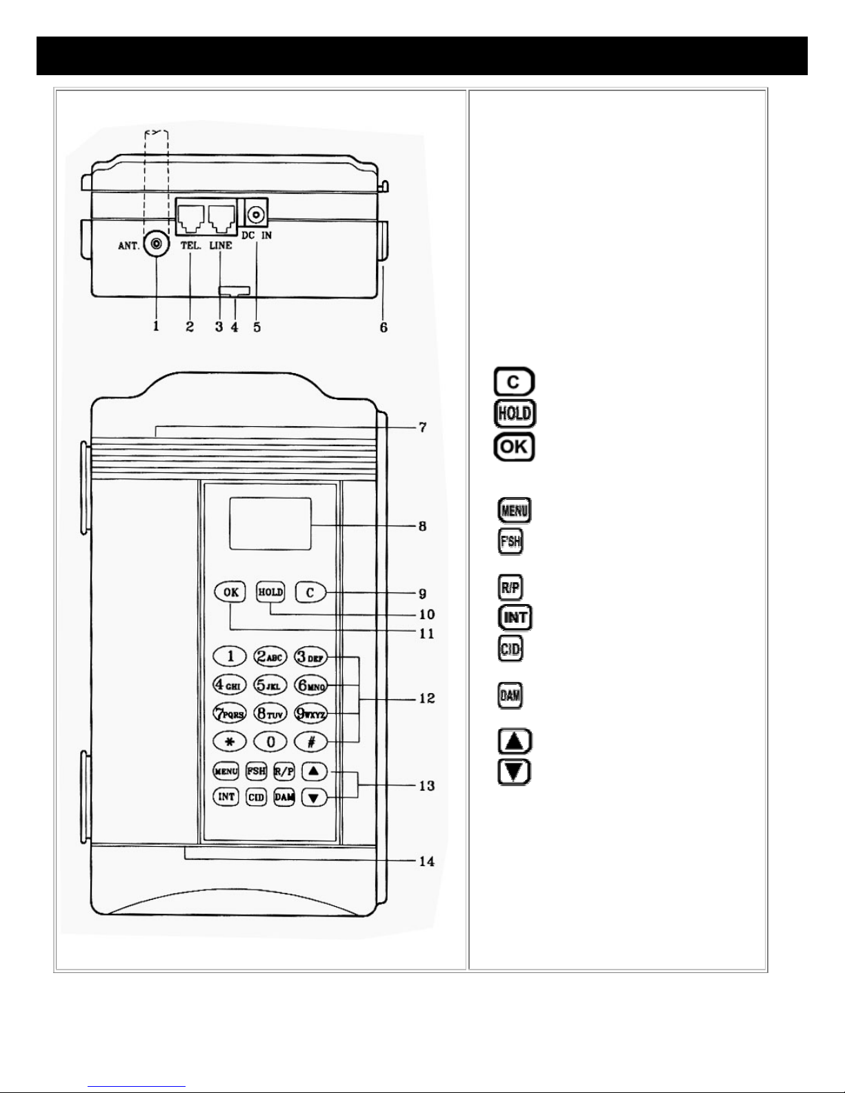
Base Unit – Wall Mount (CL-2200XP/PBX)
1. Fixed antenna or antenna plug
2. Telephone jack
3. CO line jack
4. Track for phone line
5. DC power jack
6. Bracket for connecting multiple base units
7. Speaker
8. LCD display
9.
10.
11.
12. Number buttons
13. Function buttons
dialing
number
operation
14. Microphone
button (clear/end)
button
button (confirm/send)
- select function
- FLASH or Backspace when
- Redial/Pause button
- Intercom button
- Store and recall speed dial
- Digital Answering Machine
- Volume & Up button
- Volume & Down button
9
Page 10

Portable Handset
1. Fixed antenna or antenna plug
2. Speaker
3. LCD display
4. Function buttons
channel while talking
in
Standby Mode / FLASH or Backspace
when dialing
sensitivity
in Standby Mode
- Confirm / Send
- button in Standby Mode / Scan for clear
- Clear/End
- Digital Answering Machine view function
- Hold button / Adjust microphone
- Intercom button
- Voice Scramble / select function
- Save button
- Redial / Pause button
- Volume & Up button
5. Number buttons
6. Microphone
7. Clip to lock or release battery
8. Contact points for battery charger
9. Ringer
10. Jack for headset
11. Battery pack
* For wireless PBX operation only. Please see PBX
section for more details
- Volume & Down button
.
10
Page 11
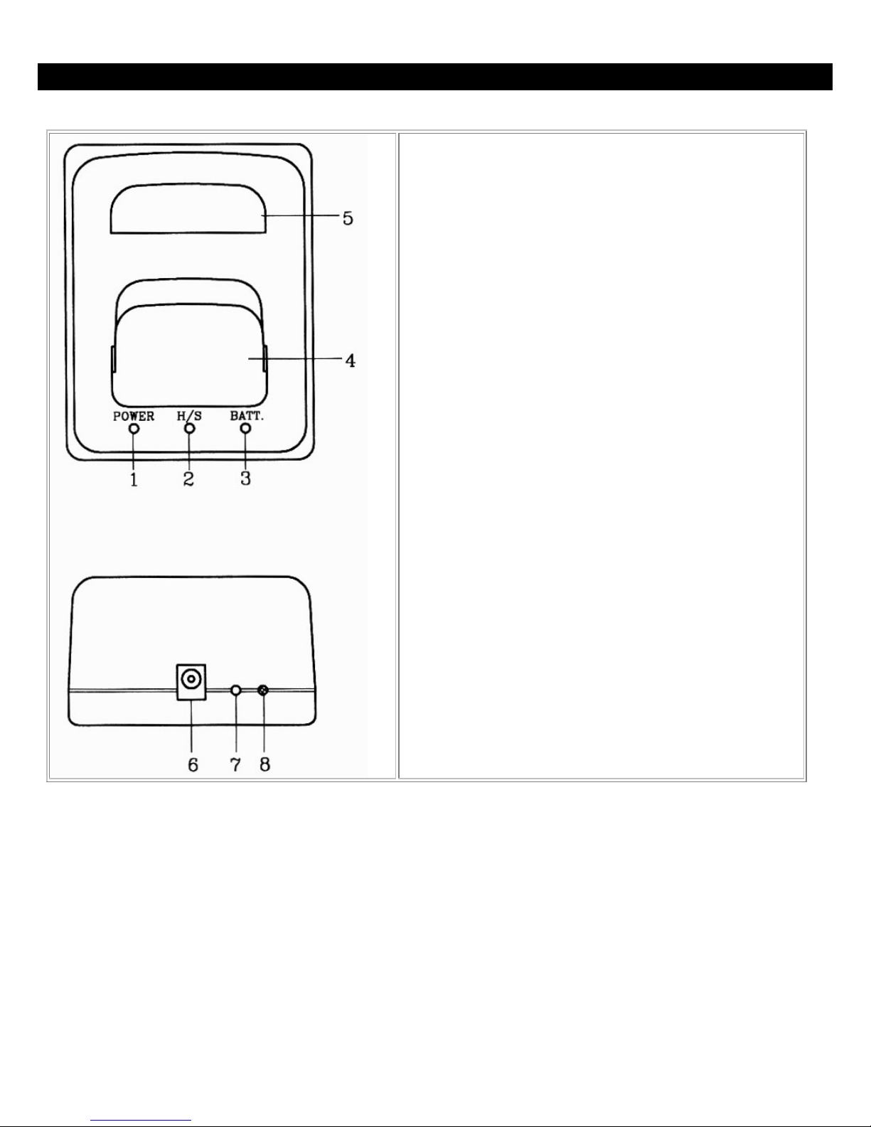
Portable Handset Charger Stand
1. Power indicator
2. Portable handset charging indicator (for front slot)
3. Battery charging indicator (for rear slot)
4. Charging slot for portable handset
5. Charging slot for spare battery
6. DC power jack
7. Discharge button
8. Discharge indicator
11
Page 12
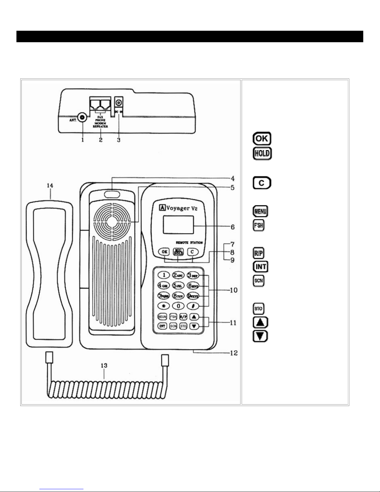
Remote Station for CL-2200XP
A Remote Station will receive the phone signal that the base unit transmits so the Remote Station functions as a live
phone line. You can install a fax machine, modem or a telephone into the two RJ 11 jacks for voice or data
communication. You can also use the Remote Station to act as a Repeater to extend the range of your phone system.
1. Fixed antenna or antenna plug
2. RJ 11 jacks
3. DC power jack
4. Hook switch
5. Speaker
6. LCD display
7.
8.
microphone sensitivity in
Standby Mode
9.
10. Number keys
11. Function buttons
when
dialing
while
talking
button (confirm/send)
- Hold button / Adjust
button (clear/end)
- select function
- FLASH or Backspace
- Redial/Pause button
- Intercom button
- Scan for clear channel
- Save button
12
12. Microphone
13. Cord for handset
14. Handset
* For wireless PBX operation only.
Please see PBX section for more
details.
- Volume & Up button
- Volume & Down button
Page 13
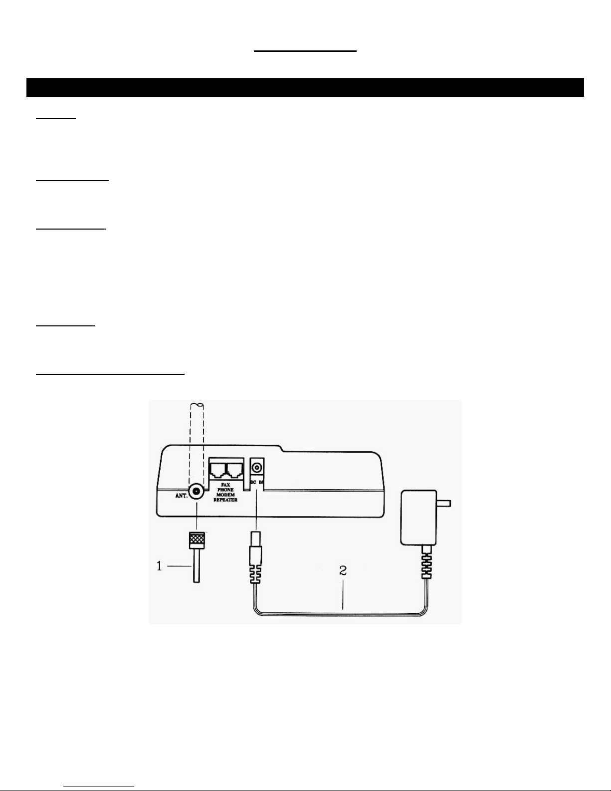
INSTALLATION - Base Unit
INSTALLATION
Antenna
Screw the L-type antenna firmly into the antenna socket. Adjust the antenna so it is pointing up.
Note: Incorrect installation of the antenna will affect the communication range and you can damage the base unit.
Telephone Line
Connect one end of the telephone line into the RJ 11 jack labeled “LINE” and the back of the base unit. Connect the
other end of the telephone line into your wall outlet.
Power Adapter
Insert the mini-plug of the power adapter into the DC power socket at the back of the base unit and the other end into
your AC power outlet on your wall. The LCD display on your base unit will show “STBY ICM”, which indicates it is in
Standby Mode, when the power is connected.
Warning! Use only the power adapter supplied. Using any other power adapter could cause serious damage to the
Base Unit.
Tone / Pulse
This unit is preset to operate on Tone dialing. This unit can be set to Pulse dialing by following the directions outlined in
“Tone or Pulse Dialing” in the Basic Operation section of this manual.
Connecting Another Telephone
You can connect another telephone into this Base Unit by connection its line cord into the jack labeled “TEL”.
13
Page 14
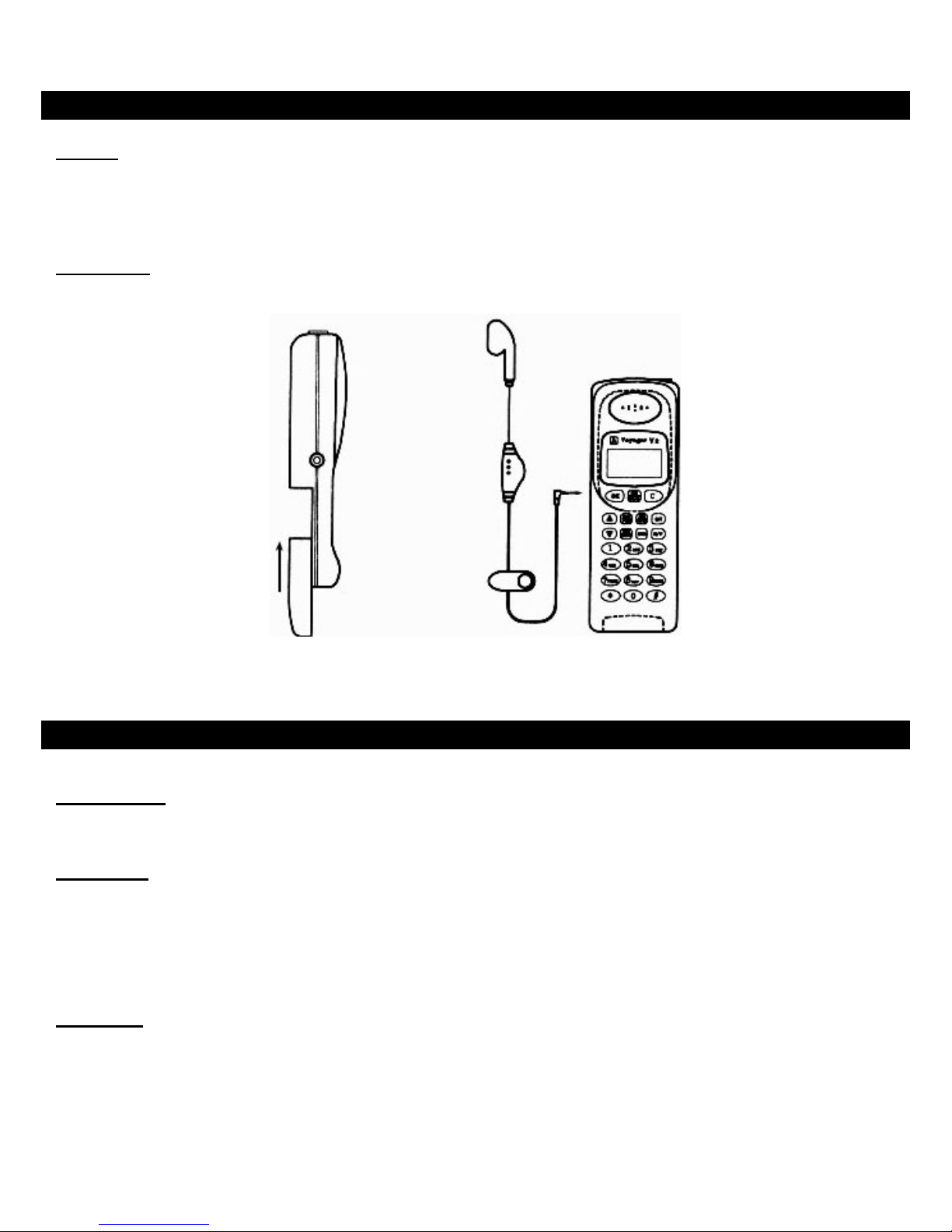
INSTALLATION - Portable Handset
Antenna
Screw the standard or short antenna firmly into the antenna socket.
Note: Incorrect installation of the antenna will affect the communication range and you can damage the Portable
Handset.
Battery Pack
Insert the battery pack into the back of the Portable Handset and gently push down until it locks in place.
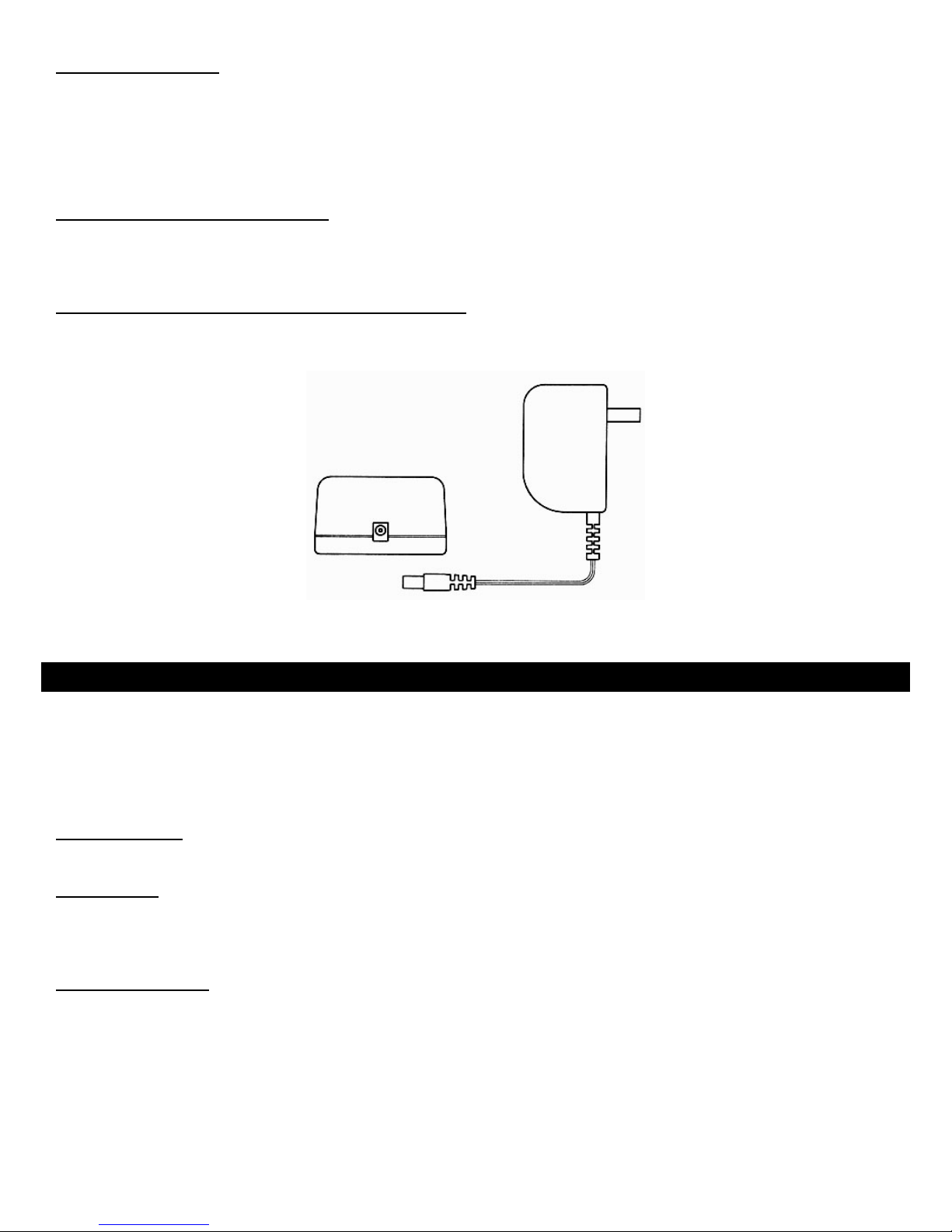
INSTALLATION - Charger Stand
Power Adapter
Insert the mini-plug of the power adapter into the DC power socket at the back of the charger stand and the other end
into your AC power outlet on your wall.
Front Cradle
The front cradle is intended to charge a battery that is already attached to a Portable Handset.
When a Portable Handset (with the battery) is placed in the front slot of the charger stand, the CPU of the Portable
Handset will automatically start monitoring the charging status of the battery. The charger will sound a confirmation beep
and
the “H/S” indictor will flash a red light to verify it is charging. When the battery is fully charged, the charger stand will
sound a series of confirmation beeps and the light will turn solid green.
Rear Cradle
A spare battery can be charged in the rear cradle for added convenience. The charger will sound a confirmation beep
and the “BATT.” indictor will flash a red light to verify it is charging. When the battery is fully charged, the charger stand
will sound a series of confirmation beeps and the light will turn solid green.
14
Page 15
Discharging A Battery
The rear cradle only is for discharging a battery. Place the battery you want to discharge into the rear cradle and press
the discharge button at the back of the charger stand. The discharge light at the back of the charger stand will flash a
yellow light and it will begin discharging your battery. The light at the front of the charger stand labeled “BATT” will be
unlit. Once the battery finishes discharging, it will automatically begin charging. The charger will sound a confirmation
beep and the “BATT.” indictor will flash a red light to verify it is charging. When the battery is fully charged, the charger
stand will sound a series of confirmation beeps and the light will turn solid green.
Using The Charger On The Base Unit
The Base Unit of the CL-2200XP-Super has a built-in charger in its cradle. To use the charger on the Base Unit, place
the Portable Handset (with battery) face down. The electrical contacts are near the front of the Portable Handset so the
battery will not charge if it is facing the wrong way.
Incoming Calls While The Portable Handset Is Charging
If there is an incoming call while the Portable Handset is being charged, the handset will ring normally and you can
answer the call. If the battery does not have enough power to answer the call, the handset will turn itself off.
INSTALLATION - Batteries
WARNING: If the battery is new or if it is completely discharged, do not charge it while it is attached to the Portable
Handset. Remove the battery from the Portable Handset and charge the battery in the rear cradle of the charger stand.
Charging a fully discharged battery while attached to the Portable Handset creates extra stress to the components of the
Portable Handset and it can erase all the internal settings.
Before Initial Use
Always charge the batteries for 8 hours before using it for the first time.
Charge Times
Charging from Base Unit 8 hours
Charging on the front cradle of the charger stand 2.5 hours
Charging on the rear cradle of the charger stand 2.5 hours
Battery Performance
Standby time 48 hours
Continuous talk time 1.7 hours
With the power off 1200 hours
Note: We recommend that you keep the Portable Handset in the charger stand when not in use to keep it fully
charged. If the phone will not be used for long period, remove the battery from the portable handset to prevent the
battery from discharging.
15
Page 16
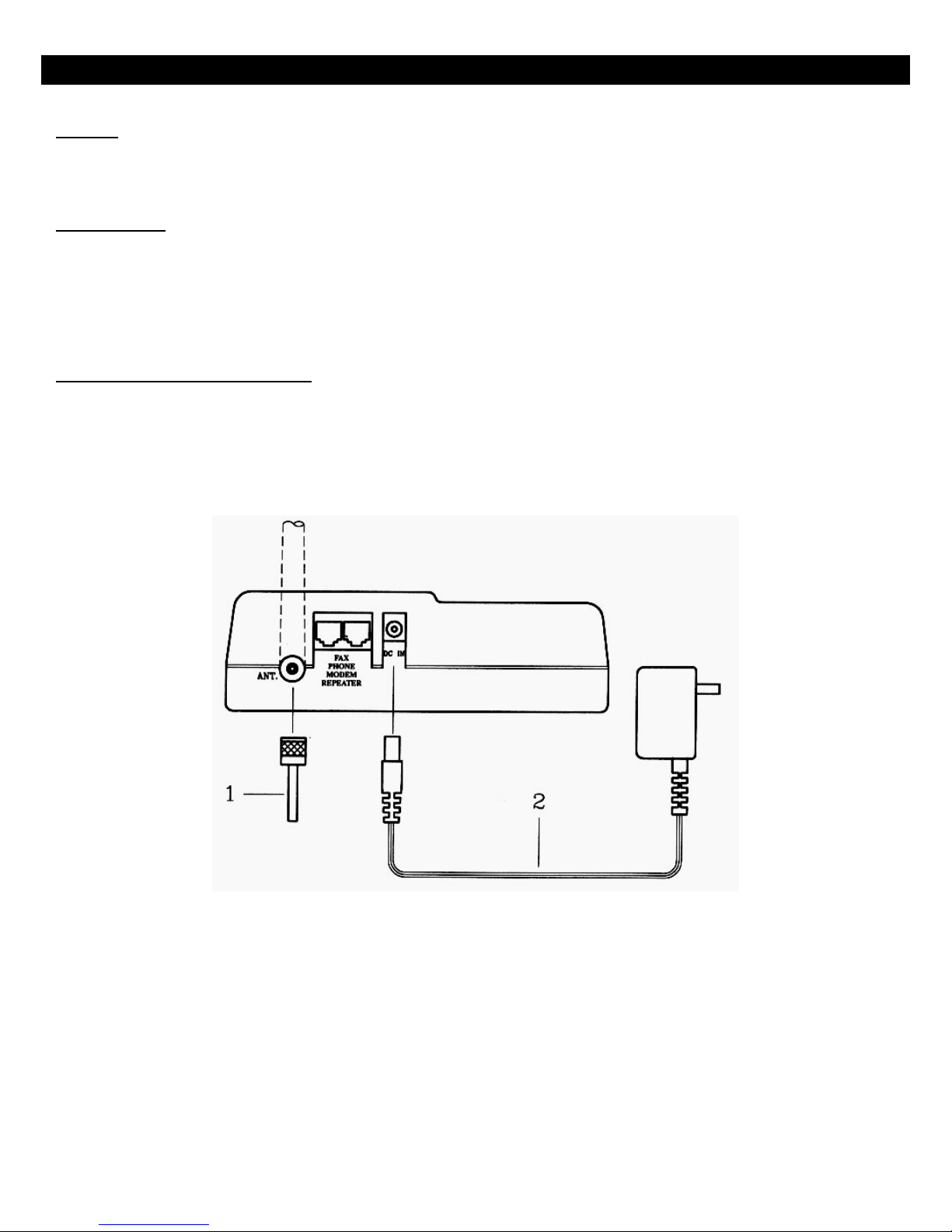
INSTALLATION - Remote Station
Antenna
Screw the L-type antenna firmly into the antenna socket. Adjust the antenna so it is pointing up.
Note: Incorrect installation of the antenna will affect the communication range and you can damage the base unit.
Power Adapter
Insert the mini-plug of the power adapter into the DC power socket at the back of the Remote Station and the other end
into your AC power outlet on your wall. The LCD display on your Remote Station will show “STBY ICM”, which
indicates it is in Standby Mode, when the power is connected.
Warning! Use only the power adapter supplied. Using any other power adapter could cause serious damage to the
Base Unit.
Connecting Your Other Equipment
A Remote Station will receive the phone signal that the base unit transmits so the Remote Station functions as a live
phone line. You can install a fax machine, modem or a telephone into the two RJ 11 jacks for voice or data
communication. You can also use the Remote Station to act as a Repeater to extend the range of your phone system.
Connect the line cord of the equipment you want to use into the jack the two RJ 11 jacks at the back of the remote
station.
16
Page 17

BASIC OPERATION
BASIC OPERATION - Turning The Power On / Off
Turning The Base Unit On / Off
Insert the mini-plug of the power adapter into the DC power socket at the back of the base unit and the other end into
your AC power outlet on your wall. The LCD display on your base unit will show
is in Standby Mode, when the power is connected.
Warning! Use only the power adapter supplied. Using any other power adapter could cause serious damage to the
Base Unit.
Turn the Base Unit off by unplugging the power adapter from the AC power outlet.
Turning The Portable Handset On / Off
Insert the battery pack into the back of the Portable Handset and gently push down until it locks in place.
will be displayed on the LCD screen and then the Portable Handset will go into standby mode.
Turn the Portable Handset off by pressing the
say “PowerOff” and the Portable Handset will turn off. Press the
and holding it down for approximately 3 seconds. The screen will
to turn the Portable Handset back on.
, which indicates it
BASIC OPERATION - Tone Or Pulse Dialing
The tone and pulse settings are made on the Base Unit only.
Default Setting – Tone Dialing
This unit is preset to operate on Tone (DTMF) dialing. The default setting is 100 ms and this should work in all locations
in North America.
Changing Tone Dialing Setting
The DTMF on CL-2200XP series of phones can be adjusted between the range of 50 ms to 200 ms. Please check with
your local phone carrier company for the correct speed if you need to make any changes to the default setting. If you are
not sure, do not change the default setting.
You can change the DTMF setting by:
1. Press
2. Press the
3. Press the
button on the Base Unit.
/ buttons until you reach the screen.
button.
17
Page 18

4. Press the / buttons until you reach the screen.
5. Press the
6. Press the
7. Press the
8. Press the
Example: The factory default setting is 100 ms
9. Press the
10. Press the
Change To Pulse Dialing
This unit can be changed to pulse dialing by:
1. Press
button.
/ buttons until you reach the screen.
button.
/ buttons until you reach the DTMF setting your desire.
button.
button twice to exit the programming functions.
button on the Base Unit.
.
2. Press the
3. Press the
4. Press the
5. Press the
6. Press the
7. Press the
8. Press the
Changing The Pulse Dialing Setting
You can change the Pulse Dialing setting by:
1. Press
/ buttons until you reach the screen.
button.
/ buttons until you reach the screen.
button.
/ buttons until you reach the screen.
button.
button twice to exit the programming functions.
button on the Base Unit.
18
Page 19

2. Press the / buttons until you reach the screen.
3. Press the
4. Press the
5. Press the
6. Press the
7. Press the
8. Press the
Example: The factory default setting is 1:2 10 ps
9. Press the
10. Press the
button.
/ buttons until you reach the screen.
button.
/ buttons until you reach the screen.
button.
/ buttons until you reach the PULSE setting your desire.
.
button.
button twice to exit the programming functions.
BASIC OPERATION - Placing A Call From The Base Unit Or Portable Handset
Making A Cellular-Type Dial Call
Make a cellular-type dial call by:
1. Key in the phone number. If you make a mistake, press the
Pressing
2. Press
For CL-2200XP/Ultra only: Alternately, you can pick up the corded handset on the Base Unit and it will
automatically dial the number.
3. Press the
Making A Normal Dial-Mode Call
Make a normal dial-mode call by:
1. Press the
2. Key in the phone number.
3. Press the
will delete all your numbers at once.
button and the Base Unit will dial the number.
button to end the call after your conversation.
button and listen for a dial tone.
button to end the call after your conversation.
button and it will delete one number at a time.
19
Page 20

BASIC OPERATION - Answering A Call
Answer A Call On The Portable Handset By Pressing Any Button
Answer an incoming call by pressing any key on the Portable Handset.
Note: The default setting is for you to be able to answer a call by pressing any button.
Answer A Call On The Portable Handset By Pressing The
The default setting on the Portable Handset is to answer an incoming call by pressing any button.
To change the setting so you can only answer the incoming call by pressing the OK button:
1. Press
2. Press the
3. Press the
4. Press the
button on the Portable Handset.
/
buttons until you reach the screen.
button.
/
buttons until you reach the screen.
Button
5. Press the
6. Press the
7. Press the
8. Press the
9. Press the
10. Press the
Answer A Call On The Base Unit
Answer an incoming call by pressing the
button.
/
buttons until you reach the screen.
button.
/
buttons until you reach the ”screen.
button.
button twice to exit the programming functions.
button.
20
Page 21

BASIC OPERATION - Redialing A Number From The Base Unit Or Portable Handset
Redialing A Number Using The Cellular Dial Mode
You can redial the last number entered into your phone by:
1. Press the
2. Press the
3. Press the
Redialing A Number Using The Normal Dial Mode
You can redial the last number entered into your phone by:
1. Press the
2. Press the
3. Press the
Note: Pressing the
Base Unit can only display the last 1 phone number dialed.
button. The phone number will appear.
button.
button to end the call after your conversation.
button. The phone number will appear.
button.
button to end the call after your conversation.
button repeatedly on the Portable Handset will show the last 5 phone numbers dialed. The
21
Page 22

ADVANCED OPERATIONS & FEATURES
ADVANCED OPERATIONS & FEATURES - Answering Options (Portable Handset Only)
Auto Answer
The Portable Handset can automatically answer an incoming call without having to press any buttons. This feature works
only while the Portable Handset is charging in its cradle.
Note: The default setting is for this feature to be off or “Inactive”. You can turn this feature on by:
1. Press
2. Press the
3. Press the
4. Press the
5. Press the
6. Press the
button on the Portable Handset.
/ buttons until you reach the screen.
button.
/ buttons until you reach the screen.
button.
/ buttons until you reach the screen.
7. Press the
8. Press the
9. Press the
10. Press the
Automatically Answer Call After One Ring
The Portable Handset can automatically answer an incoming call after only one ring.
Note: The default setting is for this feature to be off or “Inactive”. You can turn this feature on by:
1. Press
2. Press the
3. Press the
button.
/ buttons until you reach the or screen.
button.
button twice to exit the programming functions.
button on the Portable Handset.
/ buttons until you reach the screen.
button.
22
Page 23

4. Press the / buttons until you reach the screen.
5. Press the
6. Press the
7. Press the
8. Press the
9. Press the
10. Press the
Handset Vibration
The Portable Handset can vibrate and ring at the same time when there is an incoming call.
Note: The default setting is for this feature to be off or “Inactive”. You can turn this feature on by:
1. Press
button.
/ buttons until you reach the screen.
button.
/ buttons until you reach the screen.
button.
button twice to exit the programming functions.
button on the Portable Handset.
2. Press the
3. Press the
4. Press the
5. Press the
6. Press the
7. Press the
8. Press the
9. Press the
10. Press the
/ buttons until you reach the screen.
button.
/ buttons until you reach the screen.
button.
/ buttons until you reach the screen.
button.
/ buttons until you reach the screen.
button.
button twice to exit the programming functions.
23
Page 24

ADVANCED OPERATIONS & FEATURES - Audio Volume On Base Unit & Portable Handset
Microphone Volume
You can adjust the microphone sensitivity only on the Portable Handset. You can adjust the microphone sensitivity by
pressing the
Note: The microphone volume can only be adjusted when the Portable Handset is in standby mode.
Volume Control
You can adjust the volume level by pressing the
you reach a comfortable level. There are 8 volume levels.
ADVANCED OPERATIONS & FEATURES - Battery-Low Alert For The Portable Handset
button repeatedly until you reach a comfortable level. There are 8 microphone sensitivity levels.
or buttons on the Base Unit and the Portable Handset until
The Battery-Low Alert will notify you with an audible signal when the battery is low and it needs to be recharged.
You can turn this feature off by:
1. Press
2. Press the
3. Press the
4. Press the
5. Press the
6. Press the
7. Press the
8. Press the
button on the Portable Handset.
/ buttons until you reach the screen.
button.
/ buttons until you reach the screen.
button.
/ buttons until you reach the screen.
button.
button twice to exit the programming functions.
24
Page 25

ADVANCED OPERATIONS & FEATURES –
Button Confirmation Tone On The Base Unit And Portable Handset
The keypad on the Base Unit and the Portable Handset gives you an audible confirmation when a button is pressed. The
3 settings available are High/Low/Inactive.
Note: The default setting for the Button Confirmation Tone (or Key Click) is Low.
You can change the setting by:
1. Press
2. Press the
3. Press the
4. Press the
5. Press the
6. Press the
7. Press the
8. Press the
button on the Base Unit.
/ buttons until you reach the screen.
button.
/ buttons until you reach the screen.
button.
/ buttons to set the volume you prefer.
button.
button twice to exit the programming functions.
ADVANCED OPERATIONS & FEATURES - Call Transfer For The Base Unit & Portable Handset
Direct Transfer During Your Conversation
You can transfer your call during a conversation by:
1. Press the
2. Press the number of the handset that you want to transfer the call to
or
Press the
in ADVANCED OPERATIONS & FEATURES section).
Transfer After Placing Your Call On Hold
You can put your call on hold and transfer the call to another handset by:
1. Press the
2. Press the
button.
button again if you have set a preferred handset to ring (see setting Preferred Ringing Handset
button to put your call on hold.
button.
25
Page 26

3. Press the number of the handset that you want to transfer the call to
or
Press the
in ADVANCED OPERATIONS & FEATURES section).
Note: At this point, you are basically speaking with the other handset with the phone system’s intercom feature.
You would tell the person on the other handset that you have someone on hold and you are going to transfer
the call to him/her.
4. Press the
or
If the other handset does not want to receive the call, press the
person you had put on hold.
Note:
• If you do not press the handset number within 2 seconds after pressing the
system will automatically transfer the call to the preferred ringing handset.
• If you do not press the handset number within 2 seconds after pressing the
Handset, the system will automatically transfer the call to the base unit.
• If you transfer the call and the person you transferred it to do not answer within 30 seconds, the Base Unit or
Portable Handset that the transfer originated from will ring.
• If you transfer the call and the person you transferred it to do not receive it, you can talk to the person who you
button again if you have set a preferred handset to ring (see setting Preferred Ringing Handset
button to transfer the call you have put on hold to the other handset
button and you can continue talking to the
button from the Base Unit, the
button from the Portable
tried to transfer by pressing the
button.
ADVANCED OPERATIONS & FEATURES - Channels
Setting Channel Group On Base Unit Or Portable Handset
There are 10 channels within 1 channel group and there are a total of 8 channel groups. Your Base Unit and your
Portable Handset must be set on the same channel group in order for them to communicate with each other.
You might want to change the channel group on your phone if you are consistently experiencing interference from
other cordless phones in your area. You may also want to change the channel group if you want to limit which Portable
Handset(s) communicates with which Base Unit(s) within your organization. For example, this would help control how
many Portable Handsets can have access to a particular phone line.
You can change the channel group by:
1. Press
2. Press the
button.
/ buttons until you reach the screen.
3. Press the
button.
26
Page 27

4. Press the / buttons until you reach the screen.
5. Press the
6. Press the
7. Press the
8. Press the
Note: If you choose channel
Setting The Number Of Channels You Want Available On The Base Unit Or Portable Handset
You can choose to have access to 40 channels or 80 channels.
Note: The default setting is for 80 channels.
You can change the number of channels by:
1. Press
button.
/ buttons until you reach the channel group you desire.
button.
button twice to exit the programming functions.
, you will have access to all channels.
button.
2. Press the
3. Press the
4. Press the
5. Press the
6. Press the
7. Press the
8. Press the
9. Press the
10. Press the
/ buttons until you reach the screen.
button.
/ buttons until you reach the screen.
button.
/ buttons until you reach the ”screen.
button.
/ buttons until you reach the number of channel you prefer.
button.
button twice to exit the programming functions.
27
Page 28

ADVANCED OPERATIONS & FEATURES –
Channel Scan – Scanning For A Free Channel From The Portable Handset
If you are experiencing interference during your telephone conversation, press the button on your Portable
Handset and your Portable Handset will search for a clear channel.
ADVANCED OPERATIONS & FEATURES - Dialing Options
Call Restriction From The Base Unit
The Call Restriction feature restricts all outgoing call from the Base Unit. There are 2 ways you can restrict outgoing calls.
1. Stop all outgoing calls.
2. Restrict the first, first 2, or first 3 digits of the phone number.
Note: The default setting is for this feature to be off/inactive.
You can activate the Call Restriction setting on the Base Unit by:
1. Press
2. Press the
3. Press the
4. Press the
5. Press the
button on the Base Unit.
/ buttons until you reach the screen.
button.
/ buttons until you reach the screen.
button.
6. Press the
7. Press the
8. Press the
same procedure if you want to set more than one number
or
Setting the numbers to 000 will restrict ALL outgoing calls.
9. Press the
10. Press the
/ buttons until you reach the screen.
button. You will see which means there is no call restrictions set.
/ buttons to enter the number you want and then press OK to save this number. Follow the
button.
button twice to exit the programming functions.
28
Page 29

Call Restriction From The Portable Handset
The Call Restriction feature restricts all outgoing call from the Portable Handset. There are 2 ways you can restrict
outgoing calls.
1. Stop all outgoing calls.
2. Restrict the first, first 2, or first 3 digits of the phone number.
Note: The default setting is for this feature to be off/inactive.
You can activate the Call Restriction setting on the Portable Handset by:
1. Press
2. Press the
3. Press the
4. Press the
5. Press the
6. Press the
7. Press the
8. Press the
same procedure if you want to set more than one number
or
Setting the numbers to 000 will restrict ALL outgoing calls.
button on the Base Unit.
/ buttons until you reach the screen.
button.
/ buttons until you reach the screen.
button.
/ buttons until you reach the screen.
button. You will see which means there is no call restrictions set.
/ buttons to enter the number you want and then press OK to save this number. Follow the
9. Press the
10. Press the
Flash Time (For Base Unit Only)
The Flash Time is the time it takes for the phone system to switch to the other incoming call if you subscribe to the Call
Waiting feature.
Note: The default Flash Time is 600ms and it should work in most locations in North America.
You can change the Flash Time by:
1. Press
2. Press the
button.
button twice to exit the programming functions.
button on the Base Unit.
/ buttons until you reach the screen.
29
Page 30

3. Press the button.
4. Press the
5. Press the
6. Press the
7. Press the
8. Press the
Pause Time (For The Base Unit Only)
The default Pause Time is 3000ms and it should work in most locations in North America. Check with your area’s
Pause Time requirements if you need to change it.
You can change the Pause Time by:
1. Press
2. Press the
3. Press the
/ buttons until you reach the screen.
button.
/ buttons to set the Flash Time you require.
button.
button twice to exit the programming functions
button on the Base Unit.
/ buttons until you reach the screen.
button.
4. Press the
5. Press the
6. Press the
7. Press the
8. Press the
/ buttons until you reach the screen.
button.
/ buttons to set the Pause Time you require.
button.
button twice to exit the programming functions.
ADVANCED OPERATIONS & FEATURES - Energy Saving Feature – Portable Handset Only
When this feature is ON and the Portable Handset is not being used, the LCD display will turn itself off after 20 seconds
and all the buttons will be locked. The Portable Handset will become active again if there is an incoming call or if you
press the
Note: The default setting for this feature is for it to be OFF.
You can turn this feature ON by:
button.
30
Page 31

1. Press button on the Handset.
2. Press the
3. Press the
4. Press the
5. Press the
6. Press the
7. Press the
8. Press the
/ buttons until you reach the screen.
button.
/ buttons until you reach the screen.
button.
/ buttons until you reach the screen.
button.
button twice to exit the programming functions
ADVANCED OPERATIONS & FEATURES - Group Paging - For Base Unit & Portable Handset
You can page all the Portable Handsets at the same time, as long as they are in your channel group, (see the Channel
section under Advanced Operations & Features section) by:
1. Press the
2. Press the
You can do this from the Base Unit or any of the Portable Handsets. All the Portable Handsets will continue to ring until
any one Portable Handset answers the call.
button.
button.
ADVANCED OPERATIONS & FEATURES - ID Exchange (From Base Unit Only)
The ID Exchange feature works by having the Base Unit send a signal every 40 seconds to the Portable Handset (it is
communicating with) and the Portable Handset bounces the signal back to the Base Unit. The purpose of this feature is
for the Base Unit to know it is still in contact with the Portable Handset. If the signal the Base Unit sends out does not
bounce back, the Base Unit knows that the Portable Handset is either off or it is out of range.
Note: The default setting if for this feature to be “Inactive”.
You can activate the ID Exchange feature by:
1. Press
button on the Base Unit.
31
Page 32

2. Press the / buttons until you reach the screen.
3. Press the
4. Press the
5. Press the
6. Press the
7. Press the
8. Press the
button.
/ buttons until you reach the ID Exchange” screen.
button.
/ buttons to set the feature to screen.
button.
button twice to exit the programming functions
ADVANCED OPERATION & FEATURES - Intercom
You can intercom between Handset-to-Handset, Base Unit-to-Handset or Handset-to-Base Unit. If the model of your
phone system has the full-duplex feature, you can speak directly with the other party without having to press any buttons
unlike an RF 2-way radio.
Note: All the Portable Handsets should be numbered first (see Numbering Handset in the MULTIPLE SYSTEMS
section) if you have more than one Portable Handset.
You can intercom with another party by:
1. Press the
2. Press the handset number or Base Unit number of the party you are trying to intercom with
or
press the
assigned).
button.
button again and it will signal the Base Unit or the preferred ringing handset (if one has been
ADVANCED OPERATIONS & FEATURES - Keypad Backlight (For Portable Handset Only)
The Portable Handset comes with a lighted keypad for your convenience. It is a very useful feature when using the phone
in areas with poor lighting.
Note: The default setting for the Backlight is for it to be Active.
You can turn this feature off by:
1. Press
button on the Base Unit.
32
Page 33

2. Press the / buttons until you reach the screen.
3. Press the
4. Press the
5. Press the
6. Press the
7. Press the
8. Press the
button.
/ buttons until you reach the Backlight” screen.
button.
/ buttons to select the screen.
button.
button twice to exit the programming functions
ADVANCED OPERATIONS & FEATURES - Out Of Range Alert (For The Portable Handset Only)
The Portable Handset can give you an audible tone when it becomes too far away and it can no longer communicate with
the Base Unit.
Note: The default setting for the Out of Range Alert is for it to be Inactive.
You can turn this feature on by:
1. Press
2. Press the
3. Press the
4. Press the
5. Press the
6. Press the
7. Press the
8. Press the
button on the Handset.
/ buttons until you reach the screen.
button.
/ buttons until you reach the screen.
button.
/ buttons to select the option.
button.
button twice to exit the programming functions
33
Page 34

ADVANCED OPERATIONS & FEATURES - Phone Book
Storing Phone Numbers On The Base Unit
The Base Unit can store 10 phone numbers and each phone number can have a maximum of 26 digits each.
You can store your phone numbers by:
1. Enter the phone number which you want to store in the memory.
2. Press
3. Enter a number from
memory.
4. The screen will go back to the Standby mode
Storing Phone Numbers On The Portable Handset
The Portable Handset can store 10 phone numbers and each phone number can have a maximum of 20 digits
each. The Portable Handset also stores the last 5 phone numbers that were dialed and these 5 numbers are replaced in
succession once new numbers are entered.
You can store your phone numbers by:
1. Enter the phone number, which you want to store in the memory.
the button twice on the Base Unit and you will see the screen.
to . This number will be the location of this phone number in the Base Unit’s
2. Press
3. Enter a number from
Handset’s memory.
4. The screen will go back to the Standby mode
Accessing Phone Numbers From The Base Unit
You can access the numbers from the Phone Book by:
1. Press button
2. Press the
Accessing Phone Numbers From The Portable Handset
You can access the numbers from the Phone Book by:
1. Press
2. Press the
button twice on the Handset and you will see the screen.
to . This number will be the location of this phone number in the Portable
and the number on the Base Unit where you had stored that phone number.
buttons to make the call.
button and the number on the Portable Handset where you had stored that phone number.
buttons to make the call.
34
Page 35

ADVANCED OPERATIONS & FEATURES - Power Output Level – Base Unit & Portable Handset
The Power Output Levels are available in High, Low, and Auto. When the Auto setting is used, the phone detects how
much power is required to make the connection between the Base Unit and the Portable Handset and sets it accordingly.
For example, if the Portable Handset is close to the Base Unit, the phone will set itself on Low. If you take the Portable
Handset outside and you are far away from the Base Unit, they phone system detects that it needs more power to make
the connection and it will automatically switch to High power.
Note: The default setting for the Power Output Level is Auto.
You can change the Power Output Level setting by:
1. Press
2. Press the
3. Press the
4. Press the
5. Press the
6. Press the
For example:
7. Press the
button on the Base Unit or Portable Handset.
/ buttons until you reach the screen.
button.
/ buttons until you reach the screen.
button.
/ buttons until you reach the level "Auto/Low/High" you require.
or or .
button twice to exit the programming functions
ADVANCED OPERATIONS & FEATURES - Ringer
Changing The Ringer Melody On The Base Unit
There are 3 types of Ringer Melodies and you can also turn the ringer off.
Note: The default setting for the Ringer Melody is Type 2.
You can change the Ringer Melody setting by:
1. Press
2. Press the
3. Press the
button on the Base Unit.
/ buttons until you reach the screen.
button.
35
Page 36

4. Press the / buttons until you reach the screen.
5. Press the
6. Press the
Example:
7. Press the
8. Press the
Changing The Ringer Melody On The Portable Handset
There are 3 types of Ringer Melodies on the Portable Handset.
Note: The default setting for the Ringer Melody is Type 1.
You can change the Ringer Melody on the Portable Handset by:
1. Press
button.
/ buttons until you reach the ring type you require.
button.
button twice to exit the programming functions
button on the Portable Handset.
2. Press the
3. Press the
4. Press the
5. Press the
6. Press the
7. Press the
8. Press the
9. Press the
10. Press the
/ buttons until you reach the screen.
button.
/ buttons until you reach the screen.
button.
/ buttons until you reach the screen.
button.
/ buttons until you reach the Ringer Melody you prefer. Example .
button.
button twice to exit the programming functions
36
Page 37

Changing The Ringer Volume On The Portable Handset
There are 3 Ringer Volume settings on the portable handset. The settings are High, Low, and OFF.
Note: The default setting for the Ringer Volume is High.
You can change the Ringer Volume on the Portable Handset by:
1. Press
2. Press the
3. Press the
4. Press the
5. Press the
6. Press the
7. Press the
8. Press the
button on the Portable Handset.
/ buttons until you reach the screen.
button.
/ buttons until you reach the screen.
button.
/ buttons until you reach the screen.
button.
/ buttons until you reach the ringer setting you prefer.
Example
9. Press the
10. Press the
button.
button twice to exit the programming functions.
ADVANCED OPERATIONS & FEATURES - Security
Set Password On The Base Unit
The default password on the Base Unit is “1234”
You can change the Password on the Base Unit by:
1. Press
2. Press the
button on the Base Unit.
/ buttons until you reach the screen.
3. Press the
button.
37
Page 38

4. Press the / buttons until you reach the screen.
5. Press the
6. Press the
7. Press the
have a dash ( _ ) under it. The number above the dash is the one that is active and that can be changed.
8. Press the
9. Press the
Follow steps #8 and #9 for the remaining numbers. If the dash is under a number that you do not want to change,
press the
10. Press the
Set Security Code On The Base Unit
The purpose of the Security Code is to prevent another user with the same Voyager phone system to connect with your
Voyager phone system. For example, someone else has a portable handset, he is using it within the range of your Base
Unit, and he is using the same Security Code as your system. If this person can connect with your Base Unit, he can
make long distance calls or prank calls through your base unit. The Base Unit can only connect with the Portable
Handset if they both have the same Security Code.
button.
/ buttons until you reach the screen.
button. You will see the current password and the first number (starting from the left side) will
/ buttons until you reach the number you prefer. Example .
button. This will save the number you have chosen and the dash will move to the next number.
button and it will move to the next number.
button twice to exit the programming functions
Note: The default Security Code on the Base Unit is a random number. The Security Code of the Base Unit and
Portable Handset from each system is programmed at the factory to match.
You can change the Security Code on the Base Unit by:
1. Press
2. Press the
3. Press the
4. Press the
5. Press the
6. Press the
7. Press the
have a dash ( _ ) under it. The number above the dash is the one that is active and that can be changed.
button on the Base Unit.
/ buttons until you reach the screen.
button.
/ buttons until you reach the screen.
button.
/ buttons until you reach the screen.
button. You will see the current password and the first number (starting from the left side) will
38
Page 39

8. Press the / buttons until you reach the number you prefer.
Example
9. Press the
number. Follow steps #8 and #9 for the remaining numbers. If the dash is under a number that you do not want
to change, press the
10. Press the
Set Password On The Portable Handset
The purpose of the Password is for added security. You can prevent other users, including ones from your own office,
from using your Portable Handset by activating the Password feature. The user must enter the correct Password before
the Portable Handset is functional.
Note: The default password on the Base Unit is “1234”. The Password on the Base Unit must be set to match the
Password on the Portable Handset.
You can change the Password on the Portable Handset by:
1. Press
button. This will save the number you have chosen and the dash will move to the next
button twice to exit the programming functions
button on the Handset Unit.
.
button and it will move to the next number.
2. Press the
3. Press the
4. Press the
5. Press the
have a dash ( _ ) under it. The number above the dash is the one that is active and that can be changed.
6. Press the
Example
7. Press the
number. Follow steps #8 and #9 for the remaining numbers. If the dash is under a number that you do not want
to change, press the
8. Press the
/ buttons until you reach the screen.
button.
/ buttons until you reach the screen.
button. You will see the current password and the first number (starting from the left side) will
/ buttons until you reach the number you prefer.
.
button. This will save the number you have chosen and the dash will move to the next
button and it will move to the next number.
button twice to exit the programming functions
39
Page 40

Setting The Password Feature ON Or OFF On The Portable Handset
The Password feature is an option and it can be turned ON or OFF.
Note: The default setting for the Password feature is for it to be “Inactive”.
You can turn the Password feature ON by:
1. Press
2. Press the
3. Press the
4. Press the
5. Press the
6. Press the
7. Press the
8. Press the
9. Press the
button on the Handset Unit.
/ buttons until you reach the screen.
button.
/ buttons until you reach the screen.
button.
/ buttons until you reach the screen.
button.
/ buttons until you reach the screen.
button.
10. Press the
Set Security Code On The Portable Handset
The purpose of the Security Code is to prevent another user with the same Voyager phone system to connect with your
Voyager phone system. For example, someone else has a portable handset, he is using it within the range of your Base
Unit, and he is using the same Security Code as your system. If this person can connect with your Base Unit, he can
make long distance calls or prank calls through your base unit. The Base Unit can only connect with the Portable
Handset if they both have the same Security Code.
Note: The default Security Code on the Portable Handset is a random number. The Security Code of the Base Unit
and Portable Handset from each system is programmed at the factory to match.
You can change the Security Code on the Portable Handset by:
1. Press
2. Press the
3. Press the
button twice to exit the programming functions
button on the Handset Unit.
/ buttons until you reach the screen.
button.
40
Page 41

4. Press the / buttons until you reach the screen.
5. Press the
6. Press the
7. Press the
have a dash ( _ ) under it. The number above the dash is the one that is active and that can be changed.
8. Press the
9. Press the
number. Follow steps #8 and #9 for the remaining numbers. If the dash is under a number that you do not want
to change, press the
10. Press the
ADVANCED OPERATIONS & FEATURES - Speed Dialing
button.
/ buttons until you reach the screen.
button. You will see the current password and the first number (starting from the left side) will
/ buttons until you reach the number you prefer.
button. This will save the number you have chosen and the dash will move to the next
button and it will move to the next number.
button twice to exit the programming functions.
Speed Dialing can be used to quickly and easily recall commonly used phone numbers by pressing only 3 buttons.
Storing Speed Dialing Numbers On The Base Unit
The Base Unit can store 10 numbers for Speed Dialing.
You can store a phone number by:
1. Enter the phone number which you want to store in the memory.
2. Press
3. Enter a number from
memory.
4. The screen will go back to the Standby mode
Storing Speed Dialing Numbers On The Portable Handset
The Portable Handset can store 10 numbers for Speed Dialing
You can store a phone number by:
1. Enter the phone number which you want to store in the memory.
button twice on the Base Unit and you will see the screen.
to . This number will be the location of this phone number in the Base Unit’s
2. Press
3. Enter a number from
Handset’s memory.
button twice on the Handset and you will see the screen.
to . This number will be the location of this phone number in the Portable
41
Page 42

4. The screen will go back to the Standby mode
Dialing A Stored Speed Dial Number From The Base Unit
You can dial a Speed Dial number from the Base Unit by:
1. Press the
2. Press the Speed Dial number on the keypad that you want to dial.
3. Press the
4. Press the
Dialing A Stored Speed Dial Number From The Portable Handset
You can dial a Speed Dial number from the Portable Handset by:
1. Press the
2. Press the Speed Dial number on the keypad that you want to dial.
3. Press the
4. Press the
button.
button and wait for the dial tone to talk.
button to end the call after your conversation.
button.
button and wait for dial tone to talk.
button to end the call after your conversation.
ADVANCED OPERATIONS & FEATURES –
Talk Time Control – For The Base Unit & Portable Handset
The purpose of Talk Time Control is to restrict the amount of time someone can talk on the phone. This applies to
outgoing calls only. This is feature is useful for businesses that allow their customers to use the phone.
You can set the Talk Time Control between 2 minutes and 99 minutes. If you do not want to set any limit, change the
setting to “00”.
Note: The default setting for the Talk Time Control feature is 60 minutes. The phone will alert the user shortly before
the time limit is reached.
You can change the limit of the Talk Time Control by:
1. Press
2. Press the
3. Press the
button on the Base Unit or Handset.
/ buttons until you reach the screen.
button.
4. Press the
5. Press the
/ buttons until you reach the screen.
button.
42
Page 43

6. Press the / buttons until you reach the time setting you prefer.
Example:
7. Press the
8. Press the
button.
button twice to exit the programming functions.
screen.
ADVANCED OPERATIONS & FEATURES - Voice Scramble – For The Portable Handset Only
The purpose of the Digital Voice Scramble is to prevent other people from listening to your telephone conversation if they
accidentally pick your conversation from their cordless phone or if they have equipment for scanning radio signals.
Note #1: The default setting for the Digital Voice Scramble feature is “Inactive”. If this feature is not ON during a
conversation and you want to turn it ON, press the
Because the internal programming for the Portable Handset is still set on “Inactive”, the Digital Voice Scramble feature
will automatically turn itself after the conversation.
Note #2: If the Digital Voice Scramble feature is On but you feel current Scramble Code is no longer secure enough,
press the
button during your conversation and the phone will change the Scramble Code.
button and the Digital Voice Scramble feature will turn ON.
You can turn the Voice Scramble feature on by:
1. Press
2. Press the
3. Press the
4. Press the
5. Press the
6. Press the
7. Press the
button on the Portable Handset.
/ buttons until you reach the screen.
button.
/ buttons until you reach the screen.
button.
/ buttons until you reach the screen.
button.
8. Press the
9. Press the
10. Press the
/ buttons until you reach the screen.
button.
button twice to exit the programming functions
43
Page 44

MESSAGING
MESSAGING - Answering Machine
This system is equipped with a Digital Answering Machine. The following are its features:
• The LCD screen shows how many messages are in the memory.
• You can store up to 14 minutes worth of messages including your own outgoing message.
• The maximum time for each message is 3 minutes.
• The LCD screen cannot display that there is more than “99” stored messages.
• You can listen to your messages from either the Base Unit, Portable Handset, or from any other phone.
• You can answer a call at any time while the outgoing message is playing from the Base Unit or Portable Handset
by pressing the
Note #1: When the memory is full (14 minutes), the LCD screen on both the Base Unit and the Portable Handset will
show
Setting Number Of Rings Before The Digital Answering Machine Will Activate
This feature is set on the Base Unit and you have a choice between 2 rings or 4 rings.
Note: The default setting for the number of rings is 4.
You can change the number of rings to activate the Digital Answering Machine by:
1. Press
2. Press the
3. Press the
.
button on the Base Unit.
/ buttons until you reach the screen.
button.
button.
4. Press the
5. Press the
6. Press the
Example:
7. Press the
/ buttons until you reach the screen.
button.
/ buttons until you reach the number of rings you prefer.
.
button.
44
Page 45

8. Press the button twice to exit the programming functions
Recording Your Outgoing Message
You can record your outgoing message by:
1. Press the
2. Press the
3. Press the
4. Speak into the microphone at the front of the right corner of the Base Unit.
Note: Position your mouth so you are as close to the microphone as possible and speak loud and clearly for
best results.
5. Press the
Listening To Your Outgoing Message
You can listen to your outgoing message by:
1. Press the
2. Press the
3. Press the
button.
button.
button.
button to end your recording.
button.
button.
button.
4. Press the
Listening To Incoming Messages From The Base Unit
You can listen to the incoming messages on the Base Unit by:
1. Press the
2. Press the
or
Press the
3. While listening to a message, press the
or
Press the
button to end listening.
button two times to enter the screen.
button and hold it down for 3 seconds to listen to all messages.
button once (without holding the button down) to listen to the new incoming message.
button to listen to the next message.
button to go back to the screen.
45
Page 46

Deleting Messages From The Base Unit
1. Deleting One Message At A Time
You can delete the current message you are listening to by pressing the
2. Deleting All Messages In The Memory
You can delete all the messages in the memory by:
A. Press the
B. Press the
Listening To And Deleting Incoming Messages From The Portable Handset
You can listen to the incoming messages on the Portable Handset by:
1. Press the
or
Press the
applies if you have programmed a preferred Base Unit.
or
Press the
have programmed a preferred Base Unit.
button when the phone is in standby mode.
button and hold it down for 3 seconds.
button to enter the DAM mode.
button 2 times to go directly to the preferred Base Unit in a multi- Base Unit system. This only
button and then the Base Unit number in a multi-Base Unit system. This only applies if you
button while it is playing.
2. Press
Press
Press
Press
Press
Press
3. Press
Note: If you are in the DAM mode and you have no messages or if you have just finished listening to all your messages,
your Portable Handset will beep. Press the
Listening To Incoming Messages From Another Phone
You can listen to your messages from any other phone by:
1. Dial the phone number of the Voyager phone you wish to retrieve your messages from.
2. Wait for the outgoing message on the Digital Answering Machine to play and then press the button.
3. Enter your password number. If you enter the wrong password, the call will be terminated.
4. Hang up once you have finished listening to your messages.
to play all messages.
to play new messages.
to delete the current message.
to skip to the next message.
to play the previous message.
to stop playing the message.
after you have finished listening to your message(s) to return to standby mode.
button to go back to standby mode.
46
Page 47

Turning The Digital Answering Machine On/Off From The Base Unit
You can turn the Digital Answering Machine On by:
1. Press the
2. Press the
3. Press the
You can turn the Digital Answering Machine Off by:
1. Press the
2. Press the
3. Press the
button.
button again.
button. The display will show .
button.
button again.
button. The display will not show .
MESSAGING - Auto Voice Attendant (DISA)
This system is equipped with an Auto Voice Attendant or DISA (Direct Inward System Access). The caller is greeted
with a pre-recorded message that lists one or more options on how the caller would like their call transferred. For
example, you record the following message for your DISA system, “You have reached Voyager Communications. For
sales, press #11. For engineering, press #22. For technical support, press #33.” You would list all the extensions/
employees/departments you want to make available to your callers.
Outgoing Messages (OGM)
You can record up to 3 OGM’s. The first one can be similar to the following: “You have reached Voyager
Communications. For sales, press #11. For engineering, press #22. For technical support, press #33. For the operator,
press “
the call to the preferred ringing handset so you would have set the operator’s handset as the preferred one to ring. See
MULTIPLE SYSTEMS
If a call is transferred but the recipient does not answer it, the caller will hear the second OGM message. The second
OGM can say something like “The person/department you are trying to reach is not available. Please choose another
extension or press “ ” for the operator.”
The third OGM will play when the caller presses “
caller to leave a message. For example, “Please leave a message after the beep.”
” or press “ ” to leave a message on the answering machine.” (Note that pressing “ ” transfers
section for instructions.)
” to leave a message. Your recording will simply instructed the
How DISA Works
1. When the Base Unit receives an incoming call, the DISA system will play the first OGM (outgoing message) and it
waits for the caller to enter a number.
47
Page 48

2. The Base Unit follows the caller’s instructions and transfers the call. The call can only be transferred to a
Portable Handset.
3. If the caller enters a number that is not available or if he does not enter a number within 8 seconds, the DISA will
play the OGM again. If the OGM plays 2 times and there is no response, the Base Unit will return to standby
mode.
or
If the call gets transferred but the person the call is being transferred to do not answer within 25 seconds, the
DISA system will play the second OGM.
Recording Your Outgoing Messages (OGM) for DISA
You can record your Outgoing Messages (OGM) by:
1. Press the
2. Press the
3. Press the number corresponding to the OGM number you want to record (see above for an explanation on the
purpose of each OGM.)
Example " ", " " and " " are for DISA features.
4. Speak into the microphone at the front of the right corner of the Base Unit.
Note: Position your mouth so you are as close to the microphone as possible and speak loud and clearly for best
results.
5. Press the
Listening To You Outgoing Messages (OGM)
You can listen to your outgoing messages by:
1. Press the
button.
button.
button to end your recording.
button.
2. Press the
3. Press the number of the OGM that you want to listen to.
4. Press the
Turning The DISA On / Off From The Base Unit
The default setting is for the DISA to be OFF. You can turn on the DISA by:
1. Press
2. Press the
3. Press the
4. Press the
button.
button to end your recording.
button on the Base Unit.
/ buttons until you reach the screen.
button.
/ buttons until you reach the screen.
48
Page 49

5. Press the button.
6. Press the
7. Press the
8. Press the
/ buttons until you reach the screen.
button.
button twice to exit the programming functions.
MESSAGING - Memo Messaging
Memo Messaging is a convenience feature that allows you to leave a voice message for other users in your home or
business.
Recording A Memo Message
You can leave a Memo Message by:
1. Press the
2. Press the
button you will see screen.
button.
3. Press the
4. Press the
5. To review the message you just recorded, press the
6. Press the
mode.
Listening To The Memo Message
You can listen to a Memo Message by:
1. Press the
2. Press the
3. Press the
4. Press the
button and you start recording your message screen.
button you.
button when you have finished reviewing your Memo Message and to return to the standby
button. The LCD screen will show screen.
button.
button.
button when you have finished listening to the Memo Message.
button and then the button.
49
Page 50

MULTIPLE SYSTEMS
MULTIPLE SYSTEMS - Numbering Handsets
Numbering your Portable Handsets gives each one a unique identity. This is required when receiving a transferred call
and using the intercom feature. Programming is done on each Portable Handset.
You can number your handsets by:
1. Press
2. Press the
3. Press the
4. Press the
5. Press the
6. Press the
7. Press the
8. Press the
Example:
button on the Portable Handset.
/ buttons until you reach the screen.
button.
/ buttons until you reach the screen.
button.
/ buttons until you reach the screen.
button.
/ buttons until you reach the handset number you prefer.
.
9. Press the
10. Press the
button.
button twice to exit the programming functions.
MULTIPLE SYSTEMS - Ring One Or All Portable Handsets
When there is an incoming call, you can program the Base Unit to ring one specific Portable Handset (“Preferred Ringing
Handset) or to ring all Portable Handsets. If the Base Unit is programmed to ring one specific Portable Handset but that
Portable Handset does not answer after 45 seconds, the Base Unit will ring all the other Portable Handsets.
Note: You choose which Portable Handset (that Portable Handset’s number) you want to ring when there is an incoming
call. Enter “00” if you want all Portable Handsets to ring.
50
Page 51

You can program which Portable Handset will ring by:
1. Press
2. Press the
3. Press the
4. Press the
5. Press the
6. Press the
7. Press the
8. Press the
Example:
button on the Base Unit.
/ buttons until you reach the screen.
button.
/ buttons until you reach the screen.
button.
/ buttons until you reach the screen.
button.
/ buttons until you reach the handset number you prefer.
screen.
9. Press the
10. Press the
button.
button twice to exit the programming functions.
MULTIPLE SYSTEMS - Set Line Number (CO#)
If you want to set up a phone system with more than one phone line, you can combine up to 9 Base Units and up to 90
Portable Handsets. Each Base Unit has to have its own individual identity so you must assign each one with its own C.O.
(central office) Line number.
Note: In order for a multi-phone system to communicate with each other, you must set the Channel Group (see
Channels in the ADVANCED OPERATION & FEATURES
Code in the ADVANCED OPERATION & FEATURES
Setting The C.O. Number On The Base Unit
You can program the CO# on the Base Unit by:
1. Press
button on the Base Unit.
section of this manual) and Security Code (see Security
section of this manual) on all the phones to be the same.
2. Press the
3. Press the
/ buttons until you reach the screen.
button.
51
Page 52

4. Press the / buttons until you reach the screen.
5. Press the
6. Press the
7. Press the
8. Press the
Example:
9. Press the
10. Press the
Setting The C.O. Number On The Portable Handset
You can program the CO# on the Portable Handset by:
1. Press
button.
/ buttons until you reach the screen.
button.
/ buttons until you reach the CO number you prefer.
screen.
button.
button twice to exit the programming functions.
button on the Portable Handset.
2. Press the
3. Press the
4. Press the
5. Press the
6. Press the
7. Press the
8. Press the
Example:
9. Press the
10. Press the
/ buttons until you reach the screen.
button.
/ buttons until you reach the screen.
button.
/ buttons until you reach the screen.
button.
/ buttons until you reach the CO number you prefer.
.
button.
button twice to exit the programming functions.
52
Page 53

MULTIPLE SYSTEMS - Placing A Phone Call – From The Portable Handset
Choose A Specific Phone Line
You can choose a specific Phone Line number to make a call by:
1. Press the
2. Press the number button that corresponds to the Phone Line number you want to use.
Automatically Scan For An Open Phone Line
You can choose to have the phone system scan for an open Phone Line by:
1. Press the
2. Press the “
Choose The Preferred Base Unit
You can choose to directly access the Phone Line on the Preferred Base Unit (if one has been programmed) by:
1. Press the
button.
button.
button.
” button.
MULTIPLE SYSTEMS - Intercom – From The Portable Handset
This section explains how to choose a specific (or automatically scan an open one) C.O. Line in a multi-phone system.
This is required because the intercom feature works by relaying the signal through a Base Unit. This system does not
work like an RF radio, which transmits directly from one handset to another handset. This section explains how to access
a free C.O. Line but it does not explain how to make the actual intercom call. See the Intercom section in THE
ADVANCED OPERATION & FEATURES
Choose A Specific C.O. Line
You can choose a specific C.O. Line number to make a call by:
2. Press the
3. Press the number button that corresponds to the C.O. Line number you want to use.
Automatically Scan For An Open C.O. Line
You can choose to have the phone system scan for an open C.O. Line by:
1. Press the
button.
button.
in this manual for instructions on making the intercom call.
2. Press the
button.
53
Page 54

Choose The Preferred Base Unit
You can choose to directly access the C.O. Line on the Preferred Base Unit (if one has been programmed) by:
1. Press the
button.
54
Page 55

SPECIFICATIONS
Item Base Unit Handy Unit Charger Stand
Frequency 902 / 928 MHz 902 / 928 MHz
Power Source 12V DC, 1000mA 4.8V, 1200mAh Ni-MH 12V DC, 1000mAh
Dimensions Without Antenna 150 x 185 x 50 mm
6.0 x 7.4 x 2.0 inches
Weight 690 grams 270 grams 135 grams
48 x 143 x 35 mm
2.0 x 5.7 x 1.5 inches
75 x 95 x 50 mm
3.0 x 3.8 x 2.0 inches
TROUBLESHOOTING
The power light is off on the base unit.
1. Check that the AC power cord has been installed properly as outlined in the INSTALLATION
2. Check that the power outlet in the wall is working.
3. Is the power outlet in the wall controlled by a wall switch? If it is, make sure the switch is on.
The LCD display on the Portable Handset does not show “STBY” even when the battery is in.
1. Check that is battery pack is installed securely into the Portable Handset.
2. Make sure that the battery is charged. If you are not sure, use a battery pack that you know has been charged.
I cannot get a dial tone to make an outgoing call.
1. Check that the Base Unit and the Portable Handset are both set to the same Channel Group and the same
Security Code numbers (see the ADVANCED OPERATION
2. Are you waiting for the Portable Handset to ring before you try to answer the call?
Communication range is poor and I am getting an unusual amount of static and/or interference.
1. Check that the antenna on the Base Unit and the antenna on the Portable Handset are installed properly (see the
INSTALLATION
2. Are there any metal objects between the Base Unit and the Portable Handset?
I cannot use the “Tone” dial mode to place a call.
1. Make sure you are using Tone dialing in your area. If you are not, change the setting to Pulse dialing (see BASIC
OPERATION
I cannot answer an incoming call
1. Are you waiting for the Portable Handset to ring before you try to answer the call?
2. Is there a different Portable Handset that is programmed to be the Preferring Ringing Handset (see ADVANCED
OPERATION)
3. Is your Portable Handset beyond the range of the Base Unit?
Note: If you have tried to the above solutions and it has not corrected the problem, contact the dealer you had purchased
the unit from. Do not attempt to service this unit yourself as you risk electrical shock. Unauthorized service of this
equipment automatically voids any warranty by Voyager.
section).
section).
.
section).
section.
55
 Loading...