

Page 1

BARNVIEW1
7” Quad Touch Screen LCD Monitor with DVR & Camera
This manual should be retained for future reference
Page 2
IMPORTANT NOTICE
PLEASE READ BEFORE INSTALLATION
Always use discretion when installing CCTV equipment, especially when there is
perceived policy. Enquire relevant local regula tions applicable to the lawful
installation of video r ecording/surveilla nce. Third party consent may be requi red.
WIRELESS DEVICES OPERATING RANGE
Ensure the signal reception viewed from the wireless camera(s) is the best possible
reception between the camera(s) and monitor. If necessary, reduce the distance
between the camera(s) and monitor to improve overall system performance. This
system operates on a secure digital 2.4GHz frequency which reduces interference
from products such as wireless routers, cordless phones, or microwave ovens.
IMPORTANT SAFETY PRECAUTIONS
Damages caused by non-compliance with this manual will void the warranty. We will not
assume any liability for damages to items or persons caused by improper handling or
non-compliance with the safety notices. Any warranty claim wi ll be null and void in such
cases.
1. Do not drop, puncture or disassemble the camera or monitor.
2. Monitor - avoid all contact with water, and dry hands before using.
3. Never tug on the power cords. Use the plug to unplug it from the wall outlet.
4. Use the devices with care. Avoid pressi ng hard on the camera & monitor.
5. Use only the accessories and power adapters supplied by the manufacturer.
6. Check that power cables do not get crushed or damaged by sharp edges.
FCC Compliance Statement: This
device complies with Part 15 of the
FCC rules. Operation is
subjected to the following two
conditions:
(1) this device may not cause harmful interference,
and (2) this device must accept any interference
received, including interference that may cause
undesired operation.
(2011/65/EU) issued by the Commission of the
European Community. Compliance with these
directives implies conformity to the following
European Norms:
EMC: EN 301 489
LVD: EN 60950
Radio: EN 300 32 8
Products with CE Marking comply with
EMC Directive ( 2004/108/EC); Low
Voltage Directive (73/23/EEC);
R&TTE(1999/5/EC); ROHS Directive
Page 3
FCC/CE WARNING
This equipment has been tested and found to comply with limits for a Class B digital
device, pursuant to Part 15 of the FCC rules and ETSI(EN) 300328. These limits are
designed to provide reasonable protection against harmful interference in residential
installations. This equipment generates, uses, and can radiate radio frequency energy,
and if not installed and used in accordance with the instructions, may cause harmful
interference to radio communications. However, there is no guarantee that interference
will not occur in a particular installation. If this equipment does interfere with radio or
television equipment reception, which can be determined by turning the equipment off
and on, the user is encouraged to try to correct the interference by one or more of the
following measures:
-Reorient or relocate the receiving antenna.
-Move the equipment away from the receiver.
-Plug the equipment into an outlet o
n a circuit different from that to which the receiver
is connected.
-Consult the deal
er or an experienced radio/television technician for additional
suggestions.
You are cautioned that any change or modifications to the equipment not expressly
approved by the party responsible for compliance could void your authority to operate
such equipment.
DISPOSAL
If the camera system no longer functions or can no longer be repaired, it
must be di
sposed of according to the valid statutory regulations.
Disposal of spent batteries/accumulators:
You are required by law (Battery Ordinance) to return all spent batteries
and accumulators. Disposing of spent batteries/accumulators with common household
waste is prohibited! Batteries/accumulators that contain hazardous substances are
marked with the symbols on the side. These symbols indicate that it is prohibited to
dispose of these batteries/accumul
ators in the household waste. The abbreviations for
the respective heavy metals are: Cd=cadmium, Hg=mercury, Pb=lead. You can return
spent batteries and accumulators that can no longer be charged to the designated
collection points in your community, outlet
s or wherever batteries or accumulators are
sold. Following these instructions will allow you to fulfill the legal requirements and
contribute to the protection of our environment!
To comply with the FCC/CE limitation for class B device and to avoid interference,
please
follow manufacturer’s installation instruction.
Page 4

System “Device ID” and “Password” are provided on a label applied at the
back of the LCD Monitor (behind the pull out stand).
The “Device ID” and “Password” are needed for remote viewing.
For security purposes, it is recommenced for user to copy the “Device ID” and
“Password” information to the user manual, followed by removi ng the label
containing the “Device ID” and “Password” information.
Please store this manual in a safe place to protect the device ID and password
information for future reference.
Always use discretion when installing CCTV surveillance equipment
especially when there is perceived policy. Enquire regarding local regulations
applicable to the lawful installation of video recording/surveillance. Third party
consent may be required.
REQUIREMENTS FOR REMOTE VIEW
Supported Device
- iPhone / iPad / iPod Touch w/ iOS 5.0.1 or above
- Android smartphone / tablet v2.3X or above"
Note: Not suitable for Windows or Blackberry Smartphones
Recommended minimum internet upload speed
512Kbps upload speed (or bandwidth) to achieve up to an ave rage of 2FPS viewing speed.
Average viewing speed will depend on other restrictions by your ISP (internet service
provider).
Page 5
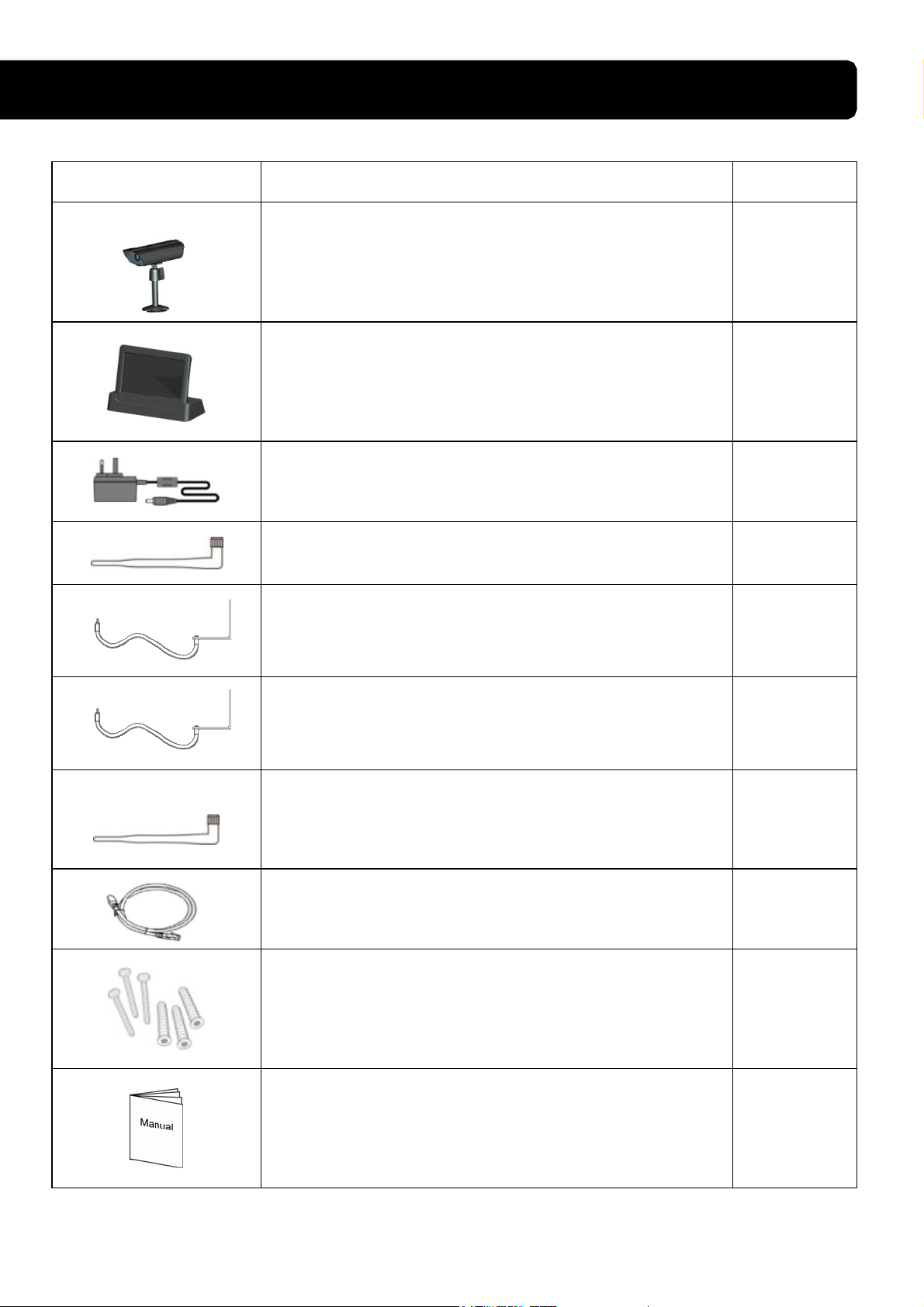
KIT CONTENT
Image Contents EA
1 EA
Wireless video camera with mounting pedestal
1 EA
Touch screen 7” LCD monitor with cradle and
built-in 2-hour rechargeable battery
5V outdoor power adapter for camera/monitor
2 EA
2 EA
5dBi antennas
1 EA
9.5 ft. antenna cable & mounting bracket for
monitor
1 EA
29.5 ft. antenna cable & mounting bracket for
camera
1 EA
3dBi antenna (Short antenna for monitor, needed
for portable use)
1 EA
Ethernet cable for internet
1 EA
Mounting hardware
1 EA
User’s Manual
Page 6

SAFETY AND INSTALLATION TIPS
LCD Touch Screen Monitor
Keep away from heat sources and high temperature places
Avoid direct sunlight
Avoid humid places
Avoid vibration
Install in a ventilated environment
Supports up to 32GB SD card (not included)
Installation Notes
Always follow manufacturer’s advice when using power t ools, steps, ladders, etc and
wear protective equipment ( e.g, safety goggles and gloves) when drilli ng holes, etc.
When using ladders ensure they are positioned on a firm stable surface at an angle and
suitably secured. Check for hidden electricity wires or water pipes before drilling any
holes. If in doubt use a cable/pipe locator. It is recommended to avoid exposing the
camera to extreme weather conditions (e.g, under a gutter which is prone to wa t er lea ks) .
After drilling any holes through an external wall for a cable, ensure the hole is sealed up
using a suitable sealant to prevent dra fts.
To prevent a fire or electrical shock hazard, do not attempt to open the housing while the
camera is exposed to wet conditions. Do not expose any wiring connections to weat hering.
If terminating any wir i ng conne ctions outdoors then use a suitable weathering box to
insulate the connectio n s .
There are no user serviceable parts inside. Refer servicing to qualified service personnel.
Camera Installation
Avoid positioning th e ca me r a so that it is facing directly at the sun as this will impair
the picture quality viewed.
Avoid pointing the camera lens directly through clear glass as the night vision LEDs
will cause a blurred image at night.
Avoid pointing the camera directly at any bushes, tree branches or moving objects that
might naturally move due to winds. This is also because if you need to use the motion
detection feature to record movement the software might record unnecessarily.
Page 7
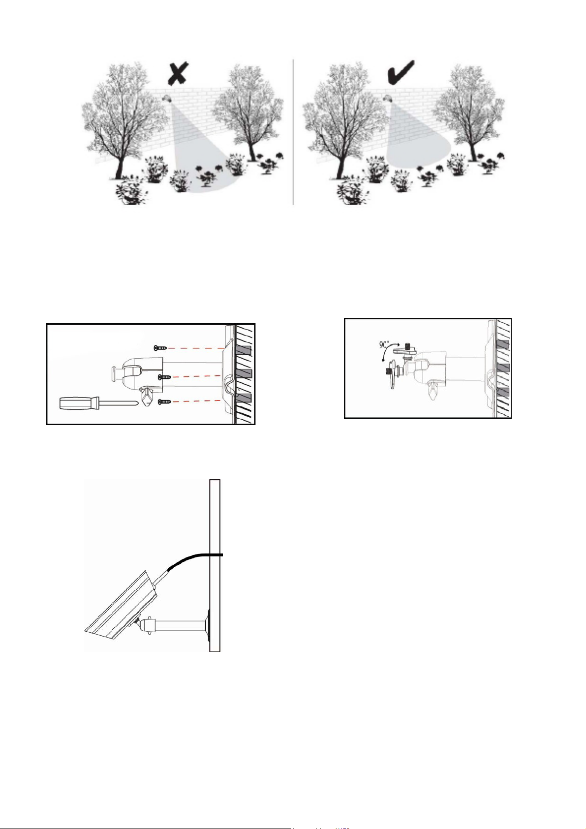
NOTE: The camera has an open field RF operating range of up to 500’.
Camera Installation
Loosen up the Thumb screw
Secure camera stand on the stable surface
Adjust proper view angle then secure
the joint with thumb screw.
Page 8
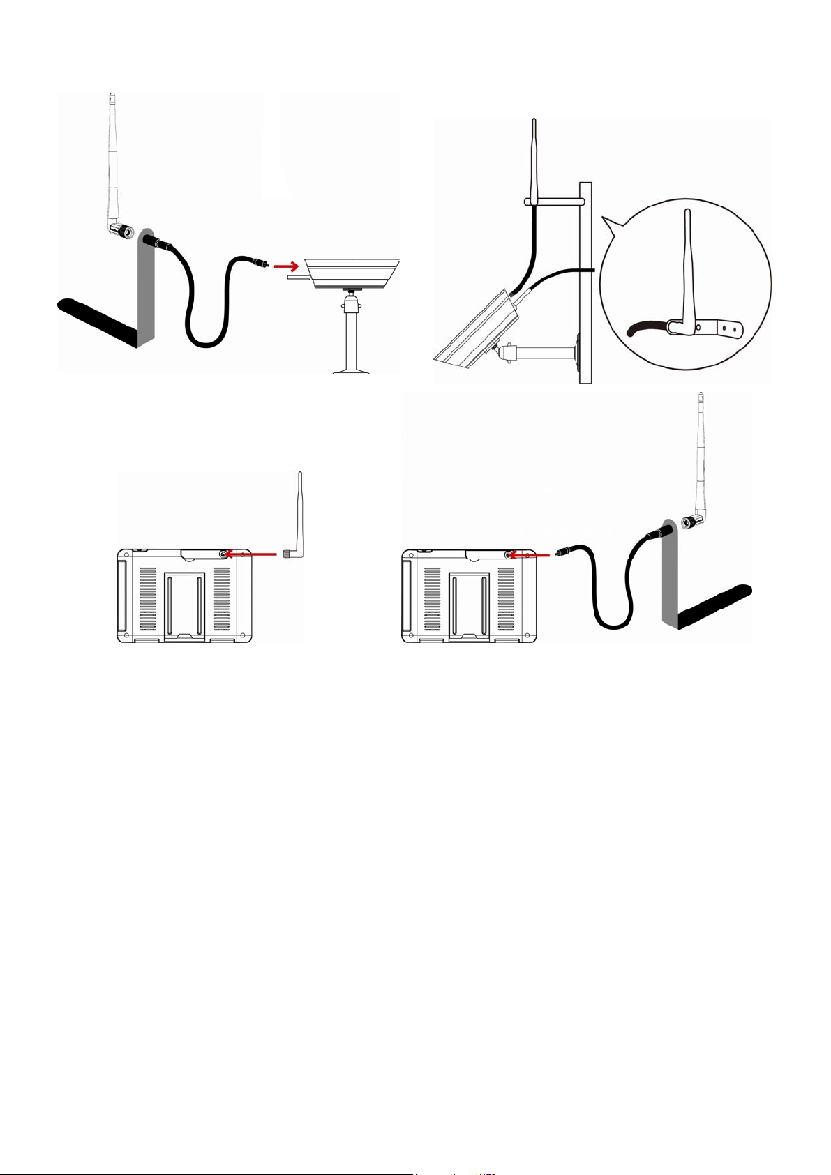
Antenna Installation
3dBi Antenna
5dBi Antenna
Setting the Camera Channel (optional)
The wireless camera is supplied preset to channel 1.
The monitor supports up to 4 cameras. Follow the steps below i n Camera Setup section to
setup or change the monitor channel of the camera. If you are adding another camera to
link with the supplied monitor in this kit, then ensure its channel is set to a different
channel to the existing camera(s).
Pairing the Camera to Receiver (optional)
Follow the steps in Camera Setup section to setup or change the channel of the camera. If
you are adding another camera to link with the supplied monitor in this kit, then ensure its
channel is set to a different channel to the existing camera(s).
Page 9
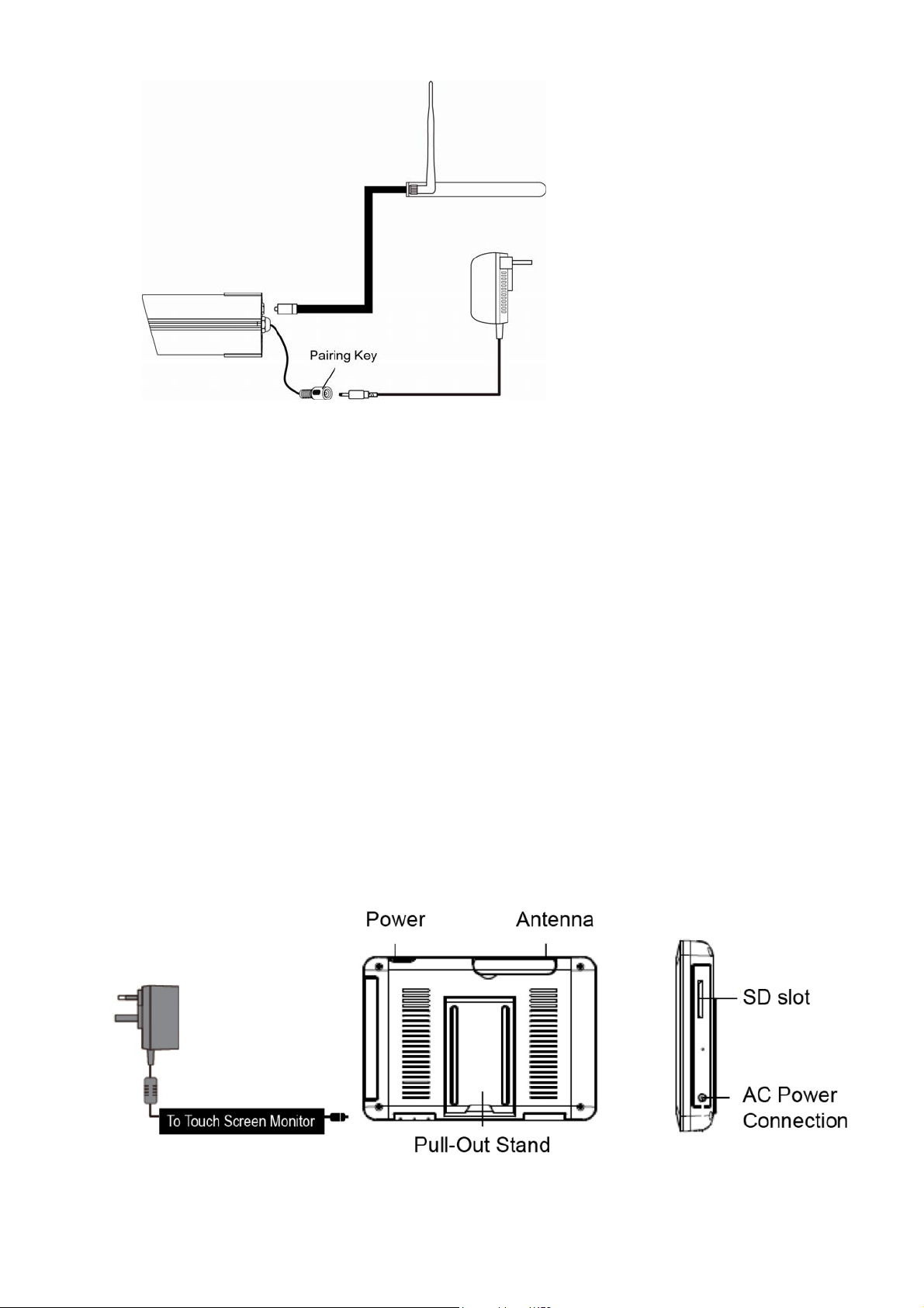
Connect the AC/DC adapter
to the nearest socket
Note:
If the camera is located within 3 – 5 feet from the monitor and the camera's volume on the
receiver is turned on, then you may hear a whistling noise on the monitor which is the
feedback picked up by the microphone . I n t h i s case please locate the camera further away
from the monitor to prevent this noise.
If the power connection to the camera is kept outdoors, ensure the connection is suitably
protected.
For further details on the installation of the camera bracket and fixings, please refer to the
Camera Installation section.
Set Up the Monitor
1. Flip out the stand, extend the antenna, connect AC/DC adapter to the input on the
side of the monitor.
To Wireless Camera
Page 10

2. Press and hold the POWER button on the top of t he monitor for 5 – 6 seconds to
power it up.
3. The receiver displays Welcome Screen for a few seconds and then transitions to the
LIVE view.
4. SD card should be inserted into SD card slot located on the side of the monitor.
Note: The screen remains dark until the camera is powered u p .
The monitor is fitted with a rechargeable battery and can operate for up to 2 hours on
battery power once fully charged (w/Power Saving function activated). The monitor can
be hand carried anywhere within operating range of the camera(s), but should be used in a
dry environment as it is not weatherproof.
System Operation
Please refer to the System Operation section for Camera, System and Recording Settings.
Remote Access
Can be done via iPhone / iPad / iPod Touch w/iOS 5.0.1 or above, Android smartphone /
tablet v2.3X or above connected to 3G/WiFi internet.
For an Android device
Please refer to the Downloading Android APP section.
For iPhone, iPad1, iPad2, New iPad
Please refer to the Downloading iPhone APP section.
Note:
The monitor must be placed on the docking cradle to allow remote viewing.
If removed from the cradle then the camera(s) can only be viewed on the monitor.
Page 11
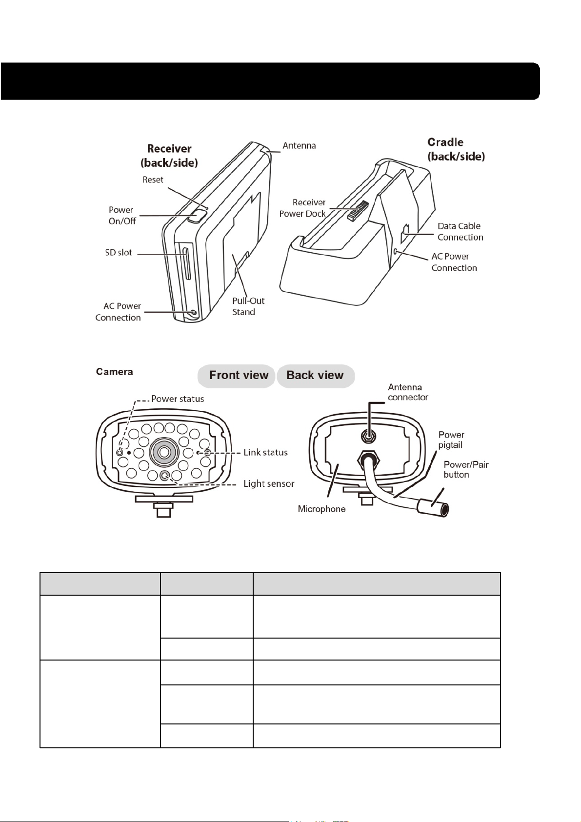
GETTING TO KNOW THE MONITOR
WHAT THE LIGHTS MEAN
Light State What it means
Power status
Link status
On
(Red)
Off The camera is off.
Flashing The camera is in pairing mode.
On
(Green)
Off The camera is in standby.
The camera is on.
The camera is connect
ed to the receiver.
Page 12
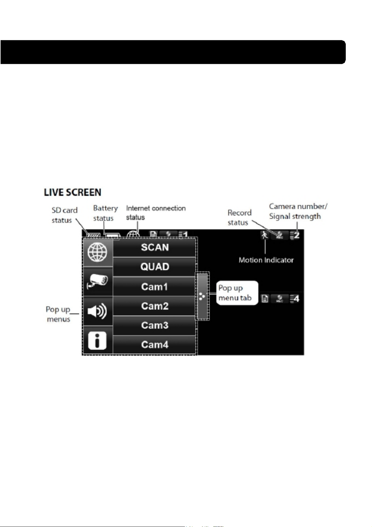
SYSTEM INTRODUCTION
Your monitor’s system software operates through a series of screens that let you choose
groups of operations. For example , when you tap on the camera icon in the Pop-up menu,
you can set how you want the main viewing screen, “the Live screen” to display images
from the paired cameras. You can scan between cameras, show all cameras on a single
screen (Quad view), or only display specific camera.
The Live screen lets you view the camera transmissions. It also lets you set up your screen
display and make adjustments to it. Icons on the screen itself let you monitor power and
camera status.
Page 13
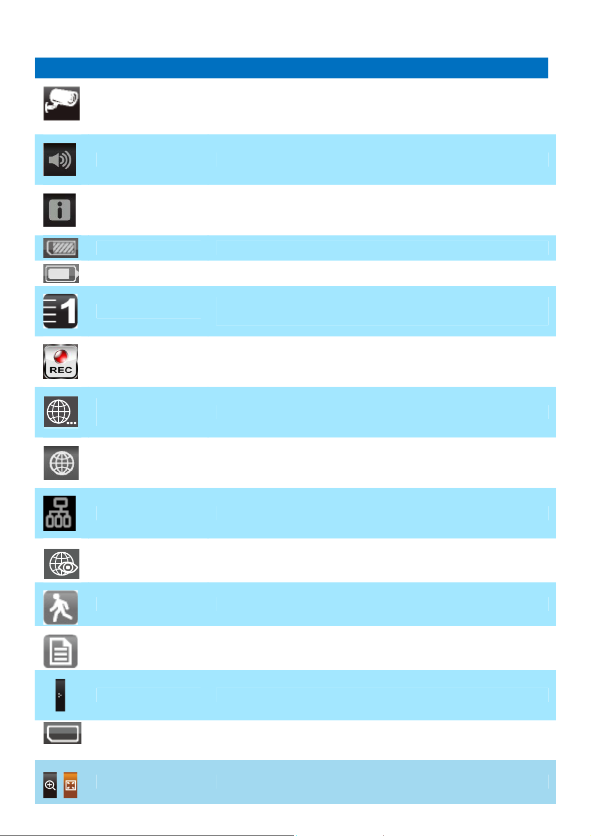
ICON WHAT THE ICON MEANS
Select how you want the Live screen to display camera input:
Camera Mode
Scan between cameras (5 seconds)
Quad view (all paired cameras display)
Full view (1 camera displays on full screen)
Volume
System Settings
SD Capacity Indicates memory capacity remaining.
Battery Capacity Displays battery capacity. This graphic shows battery at nearly full.
Camera Number
Record Status
Connecting to the
Internet
Adjust the volume level.
Access the system software operation and setting page or view recorded
events.
Displays the camera number and signal strength through the status lines
to the left of the number.
Tap to start or stop recording for that camera
• Steady on - Not recording • Flashing - Recording
Connecting your system to the internet.
Internet Connected Connects your system to the internet.
Intranet Connected Connects your system to the intranet.
Remote View Indicates remote viewing is in process.
Motion System indicates motion detection recording in progress.
Scheduled System indicates scheduled recording in progress.
Pop Up Menu Tab Opens and closes the pop up menu display.
No SD Card
Indicator
Displays red when the SD card is not present or is damaged.
Zoom Zoom in / out of a particular section of the live video
Page 14
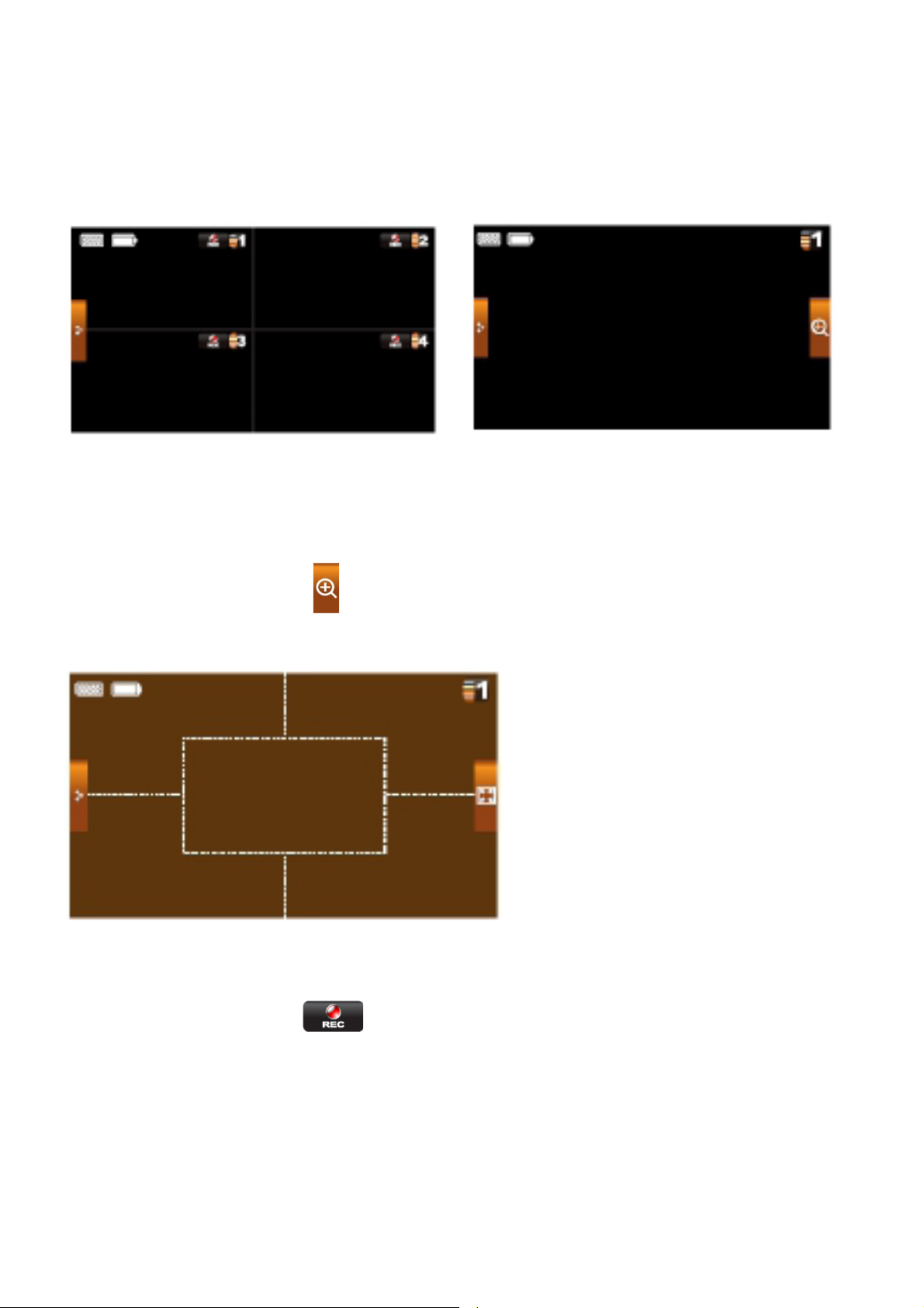
Live Screen Displays
The Live screen displays in 2 views - Quad View or Full View. Quad View displays the
images in 4 quadrants (only display camera that is ON). Tap a quadrant to display single
camera view / full view. Tap on that image again to return to Quad View.
Zoom Feature
To zoom into a particular area,
1. Go to full view, then tap
2. Select the zone by tapping the zone area to view zoom in screen.
to activate zoom mode.
Recording Live Video
1. On the Live screen, tap for the camera to begin recording.
2. Tap it again to stop recording.
You can record all cameras at the same time. With manual recording, each recording
session (video clip per camera) is two minutes in length.
Page 15
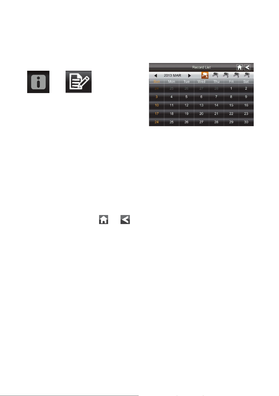
Playing Back Recorded Video
From the pop-up menu, tap the following
icons
The Record List screen displays:
1. Tap on the highlighte d day containing the recording you want to view.
The Record List screen will display that day’s recordings listed in a folder.
If you tap on a day that is not highlighted, a folder displays with no recordings
listed.
2. Tap on the recording you want to view. It displays on the screen.
3. Tap on any area of the screen that does not have control icons to bring up the
playback progress bar. Tap that area again to close it.
4. While playback progress is visible, you can fast forward/rewind by dra g gi ng the
playback bar.
5. When playback ends, tap
or to return to the Record List.
Page 16
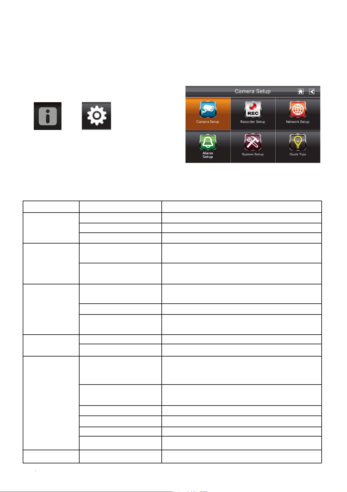
SYSTEM MENU
N
N
p
N
From the pop-up menu, tap the following
icons
The Main Screen displays:
The SYSTEM MENU highlights the Camera Setup option as the default.
Main Screen Sub Screens What it Does
Camera Setup
Camera Setup Pairs new cameras to the receiver.
Camera on Makes the cameras visible to the monitor.
Recorder Setup
etwork Setup
System Setup
Brightness
Motion Detection Records when something moves in front of the
Schedule Record Set up a schedule for pre-determined recording
Internet Setup Select the type of internet connection to be
Security Code Set a security code for remote access.
etwork Inform
Period Set a length of time for the alarm to sound. Alarm Setup
Melody Select a melody to play for the alarm.
Power Saving Temporarily turns off the LCD after the
Screen Auto Lock Locks the screen from fu
ation Displays information about your network and
Brightens or darkens the video of that camera.
camera. Continues recording for 2 minutes.
times and lengths.
used.
the receiver’s unique DID number.
system is idle for 2 minutes to conserve
ower.
rther activity until the
screen is unlocked.
Quick Tips
Time Set th
Format Storage Formats / erases all the data on the SD card.
System Upgrade
Default Lists the
/A Provides a list of 10 common questions.
Upgrades the receiver firmware.
e time in 12-hour increments.
original system defaults.
Page 17
SYSTEM OPERATION
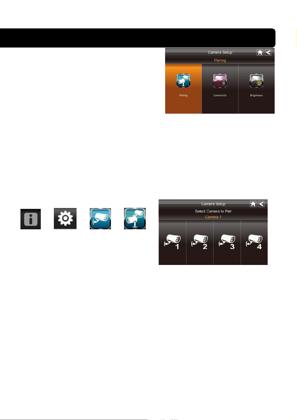
Camera Setup Screen
Tap on camera setup.
This screen should display:
Camera Pairing
Your camera is paired to the monitor at the factory to channel 1.
To add new camera(s) to your system, you have to pair it to the different channel(s).
From the pop-up menu, tap the following
icons
The Main Screen displays:
1. Tap the camera image you want to pair. A processing icon displays for a 60 second
countdown.
2. Press and release the Pairing button on that camera’s power cord (please refer to the
Getting to Know the Monitor and Camera section). The system will indicate pairing is
successful when pairing completes.
3. The system will automatically adjust the Camera On screen.
Page 18
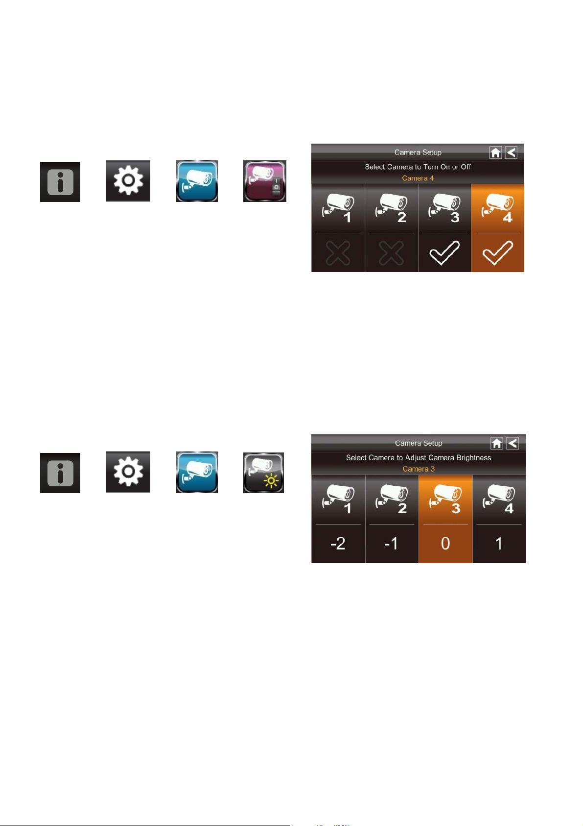
Camera Activation
When you add a camera to your system, the system will turn on the camera automatically.
From the pop-up menu, tap the following
icons
The screen displays:
An X indicates a camera is OFF, a check indicates ON. Tap on the camera to turn it ON or
OFF.
Brightness
From the pop-up menu, tap the following
icons
The screen displays:
Tap the camera to change brightness level. The default brightness is 0, and the range is
from -2 through 2.
Page 19
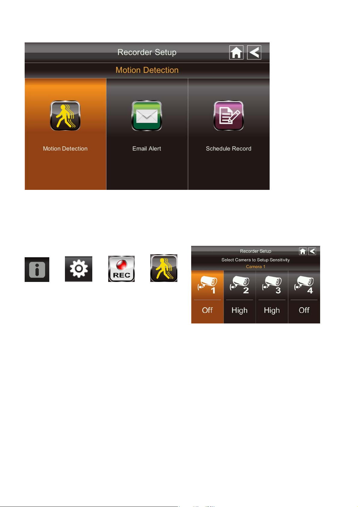
Recorder Setup Screen
Motion Detection
From the pop-up menu, tap the following
icons
The screen displays:
Tap the cameras to set the sensitivity to Off, Low or High.
Default = low. The screen will return to the Motion Detection screen after 10 seconds or
when you press the Back icon.
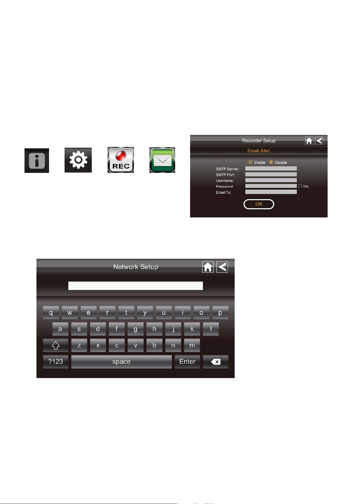
Email Alert
The system can notify you when it detects motion from any camera by sending you an
email alert. The email alert contains information such as the time that motion was detected
and by which camera. In order to enable the Email Alert function, you must enter both
incoming and outgoing email addresse s.
We strongly recommend you use Gmail to set up as the outgoing email server.
The outgoing email server (SMTP server) is responsible for sending out the email
notification to tell users when the system detects motion from any camera (Motion
Detection must be activated).
Page 20
The incoming mail server (Email To) receives the email notification sent from the SMTP
server, The user must be able to receive email on a Windows PC or on mobile devices
(such as an iPhone, iPad or Android smartphone or tablet) to receive e-mail alerts from the
system.
When you receive an email alert, you can view live video from iPhone, iPad, Android
smartphone or Android tablet through apps. Free apps are available through the iTunes
App store or the Android Market.
From the pop-up menu, tap the following
icons as they appear on the screens:
The screen displays:
1. Tap Enable to activate Email Alert or Disable to deactivate it.
2. Tap on the SMTP Server field. A keyboard screen displays.
3. Enter your outgoing e-mail SMTP server (example: johndoe@gmail.com). You can
switch the keyboard from alphabetical characters to numbers/symbols and back again
by tapping the field to the left of the space bar. Tap Return. The Email Alert screen
displays again.
4. Repeat the previous step for the Password field. Tap Return. The password entered
here must be the same password as the password for the outgoing email account.
5. Repeat Step 3 for the Email To field. Only one incoming email account will be
accepted by the system. The incoming email account can be different from the
Page 21
outgoing email account.
6. Tap OK to save the settings, then tap
If you are using Gmail as the outgoing SMTP server, check SSL and use the data in
the followin g table:
For Gmail
SMTP Server Smtp.gmail.com Enter this.
SMTP Port 465 Enter this.
Username XXXX@gmail.com Enter your gmail address in full,
Password XXXXXXXXXX Enter the password for this
Email to XXXX@gmail.com Enter the email address where
to return to the previous screen.
including @gmail .c om.
gmail account.
you want the alerts sent.
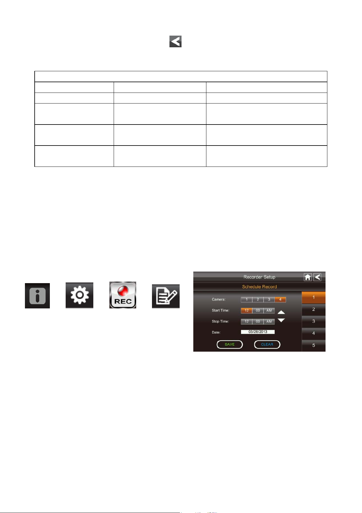
Schedule Record
Up to 5 scheduled recording sessions are available in a single day. You are limited to the
size of the SD card for how long a total recording time you have. These recording sessions
must begin and end within a single 24-hour period. They cannot cross into the next day.
From the pop-up menu, tap the following
icons
The Schedule Record screen displays:
1. Tap the camera/channel number you want to record (1 - 4). Multiple cameras can be
selected.
2. Set the recording start and end time. Tap the hour and minutes boxes separately and
use the UP and DOWN arrows to scroll through the times.
3. Tap the AM/PM block to toggle between them.
4. Tap on the blank DATE box. The Schedule Record Calendar screen displays.
Page 22
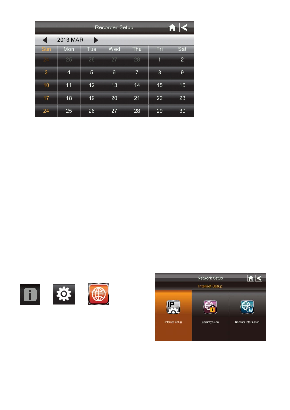
5. Tap on the date you want the record ing. The previous screen displays.
6. Set up the recording and then tap Save. You can select another recording session to
schedule.
Clear a Scheduled Recording
1. Access the Schedule Record screen.
2. Tap on the scheduled recording you want to clear (1-5). The screen displays the
settings for that schedule.
3. Tap CLEAR. The screen resets to the default values for that recording slot.
Network Setup Screen
The Network Setup screen allows you to select your internet type, set a security code. You
can also display system default configuration.
From the pop-up menu, tap the following
icons
The Network Setup screen displays:
Page 23
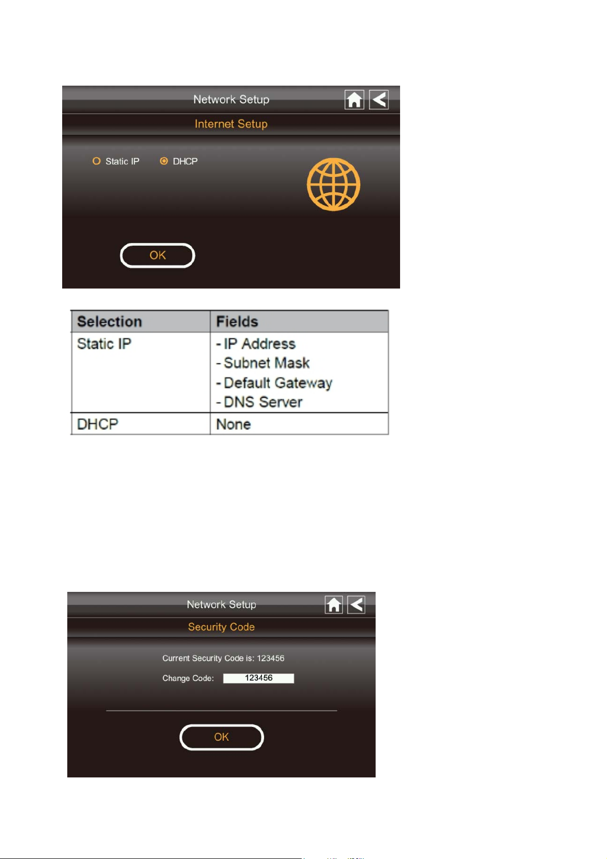
Internet Setup
1. Tap Internet Setup icon to display the Internet Setup screen.
2. Tap on your selection and fill in the fields requested. Tap OK.
3. Tap OK at the system reboot prompt. The Network Setup screen displays.
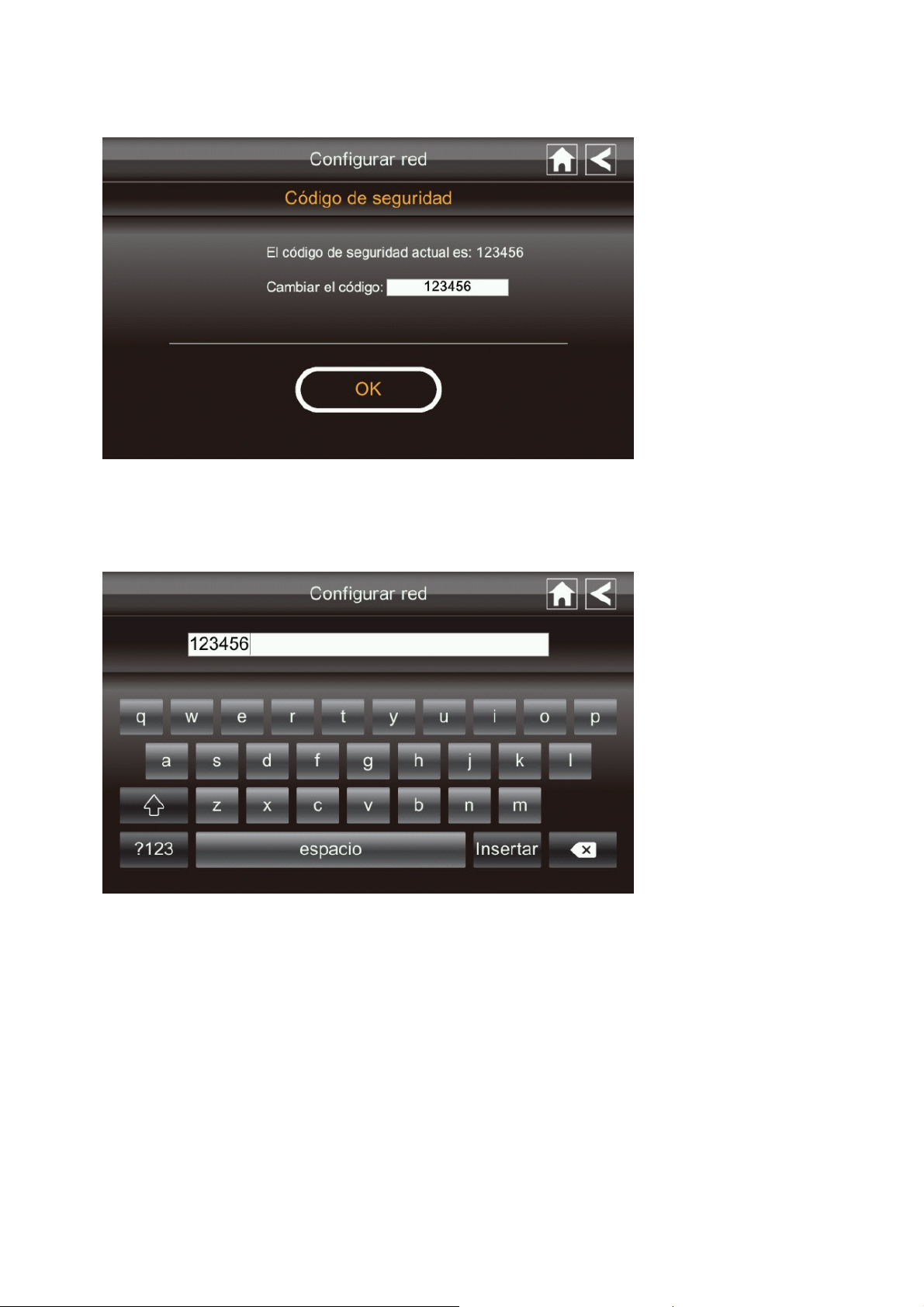
Security Code
Set up your security code to limit who can have access to the system from a remote
location.
1. Tap Security Code icon to display the Security Code screen.
Page 24
2. If you have previously entered a code, the screen will display your curr e nt code
3. Tap on the change code field, a key board screen displays.
4. Enter your security code.
5. Tap OK. The system will return to Network Setup screen.
Note: Security code must be entered to gain remote access. To protect your privacy,
please be sure to change the default password 123456 into your personal securit y code.
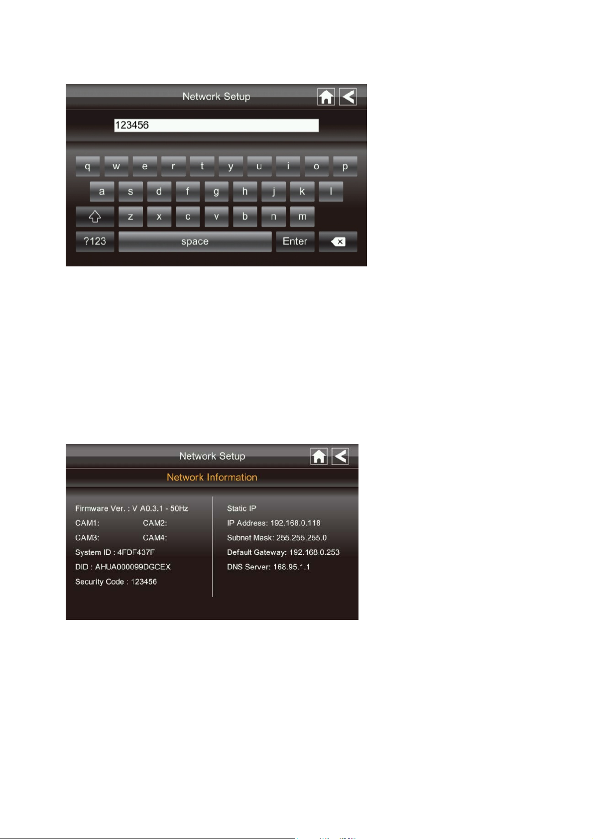
Network Information
1. Tap the Network Information icon to display the Network Inform ation screen.
2. Tap the BACK arrow to return to the previous screen.
Note:
The DID is a unique code specific to your monitor and is required to gain remote access
to your cameras over the internet.
The information in the DHCP setting is assigned to your monitor from your home router.
Page 25
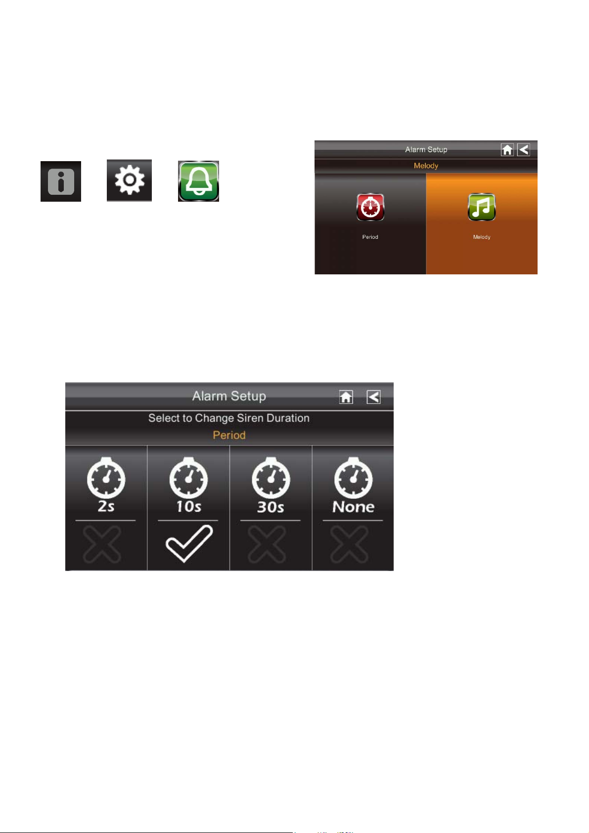
Alarm Setup Screen
From the Alarm Setup screen, you can:
Set the length of time the alarm sounds
Select a melody for the alarm.
Period
This selection allows you to select the alarm/siren duration for Clock Alarm and Timer.
1. Tap Period. The Set Siren Duration screen displays.
2. Select the alarm duration time required
3. Tap the BACK arrow to return to the previous screen.
Page 26
Melody
This selection allows you to select a melody for the siren.
1. Tap Melody. The Change Siren Melody screen displays.
2. Select the melody required
3. Tap the BACK arrow to return to the previous screen.
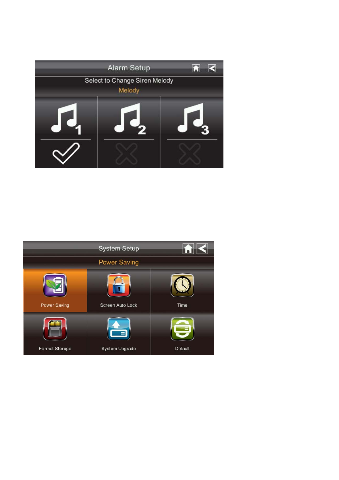
System Setup Screen
Power Saving
In Power Saving mode, the monitor will shut off LCD after idle for 2 minutes. Press
Power button once to reactive the monitor.
If a motion detection event or scheduled recording begins, the LCD turns back on
automatically.
Page 27
1. Tap Power Saving Enable to activate power saving. Default is off.
2. A check mark appears on your selection.
3. Tap the BACK arrow to return to the previous screen.
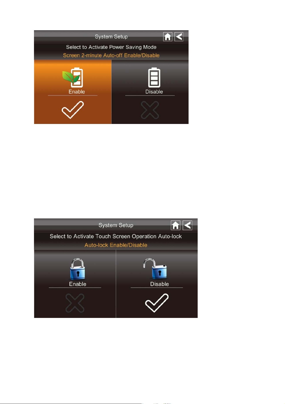
Screen Auto Lock
In Auto Lock mode, the monitor will enter screen lock mode after it has been idle for 2
minutes. Auto Lock disables the touch screen and removes the icons from the display.
1. Tap Screen Auto Lock
2. Tap your selection; a check mark displays.
3. Tap the BACK arrow to return to the previous screen.
Note: From the Live scr een, tap the Power button once to unlock the screen and
return to normal touch screen operation.
Page 28
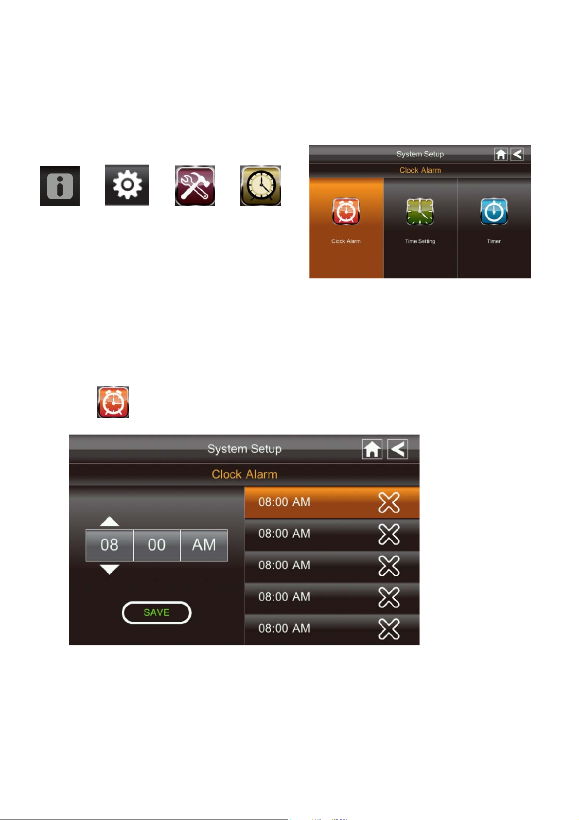
Time
The Time screen lets you set up clock alarms, set the system time, and set a timer.
From the pop-up menu, tap the following
icons
The screen displays:
Clock Alarm
This feature operates as an inde pendent alarm clock. It does not affect the operation of
live video or recording video.
1. Tap
2. Tap on an alarm button (total of 5 to select from).
3. Tap on the hour/minutes block then UP/DOWN arrows to set the time.
4. Tap on AM/PM to toggle between the two.
5. Tap SAVE, then back.
to display the Clock Alarm screen.
Page 29
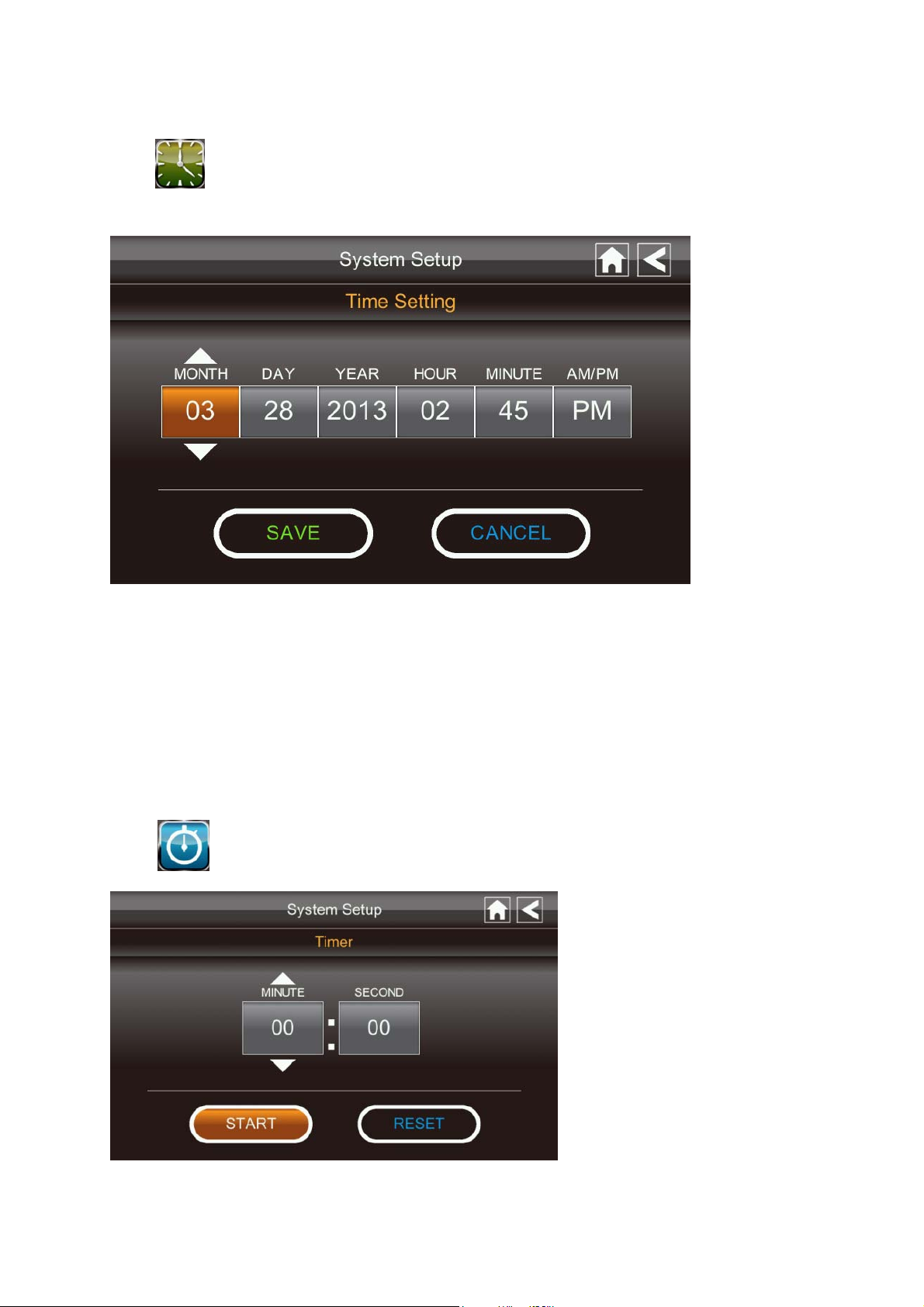
Time Setting
This screen contains fields to set the Month, Day, Year, Hour, Minute and AM/PM.
1. Tap
2. Tap on each field to set it. The UP/DOWN arrows shift to that field. Use UP/DOWN
to set the field.
3. Tap on the AM/PM block to switch between the two.
4. Tap SAVE when you are finished.
to display the Time Setting screen.
Timer
This feature operates as an inde pendent alarm clock. It does not affect the operation of
live video of recording video.
1. Tap
to display the Time Setting screen.
2. Tap on each field to set it. Use UP/DOWN to set the field.
Page 30
3. Tap START to begin the time. When the time reaches 00:00, an alarm beeps until you
tap OK.
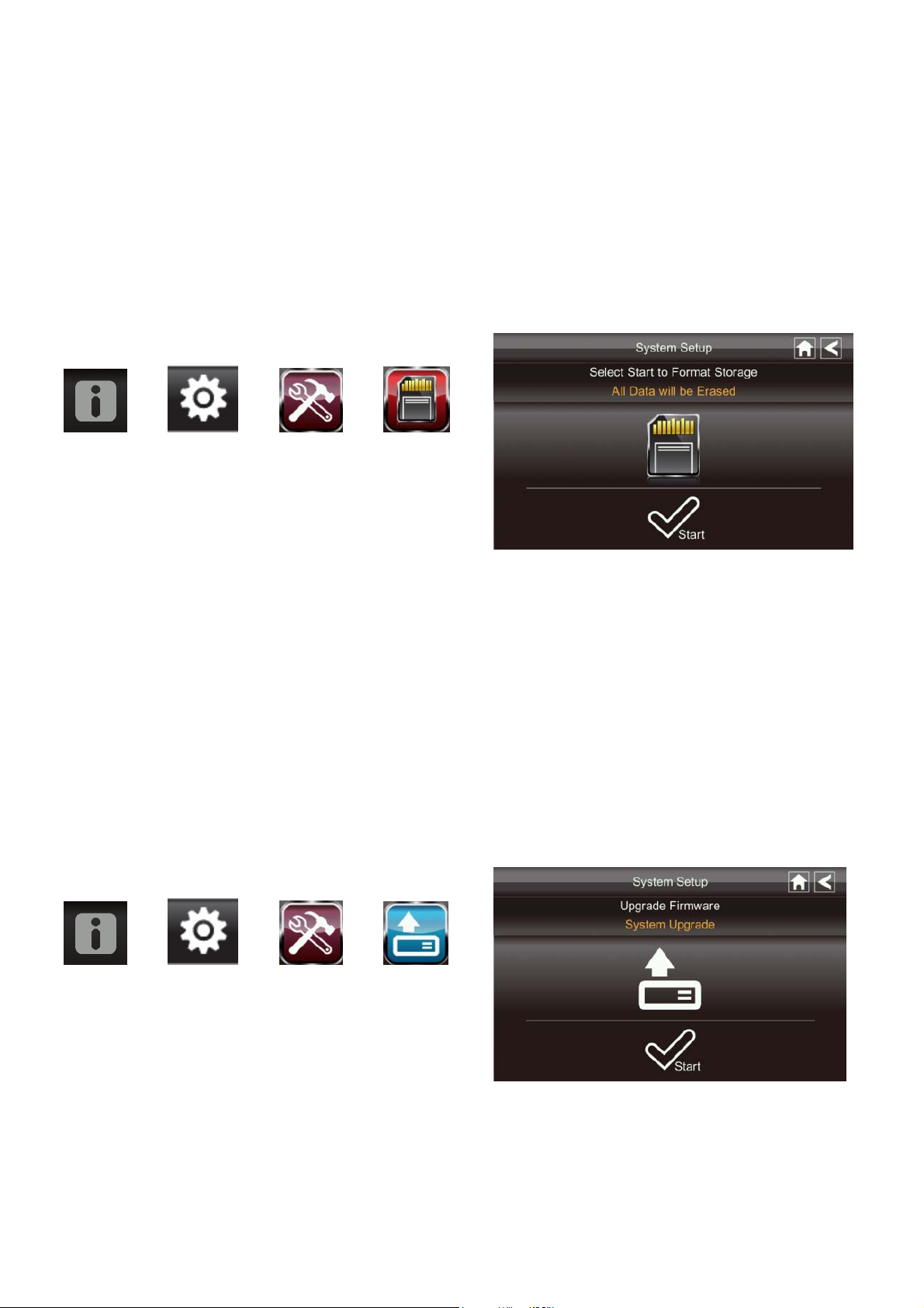
Format Storage
When using an SD card, it is highly recommended that you format the card using these
procedures. Formatting any SD card deletes all files on tha t card.
From the pop-up menu, tap the following
icons
The Format Storage screen displays:
1. Tap on START; a warning statement displays.
2. Tap OK to proceed to format storage or tap CANCEL to discontinue.
3. The system will indicate success or failure.
System Upgrade
To upgrade the firmware from the vendor website, you must download and store it in the
SD card root directory.
From the pop-up menu, tap the following
icons
Press the Start button to upgrade the firmware.
The screen displays:
Page 31
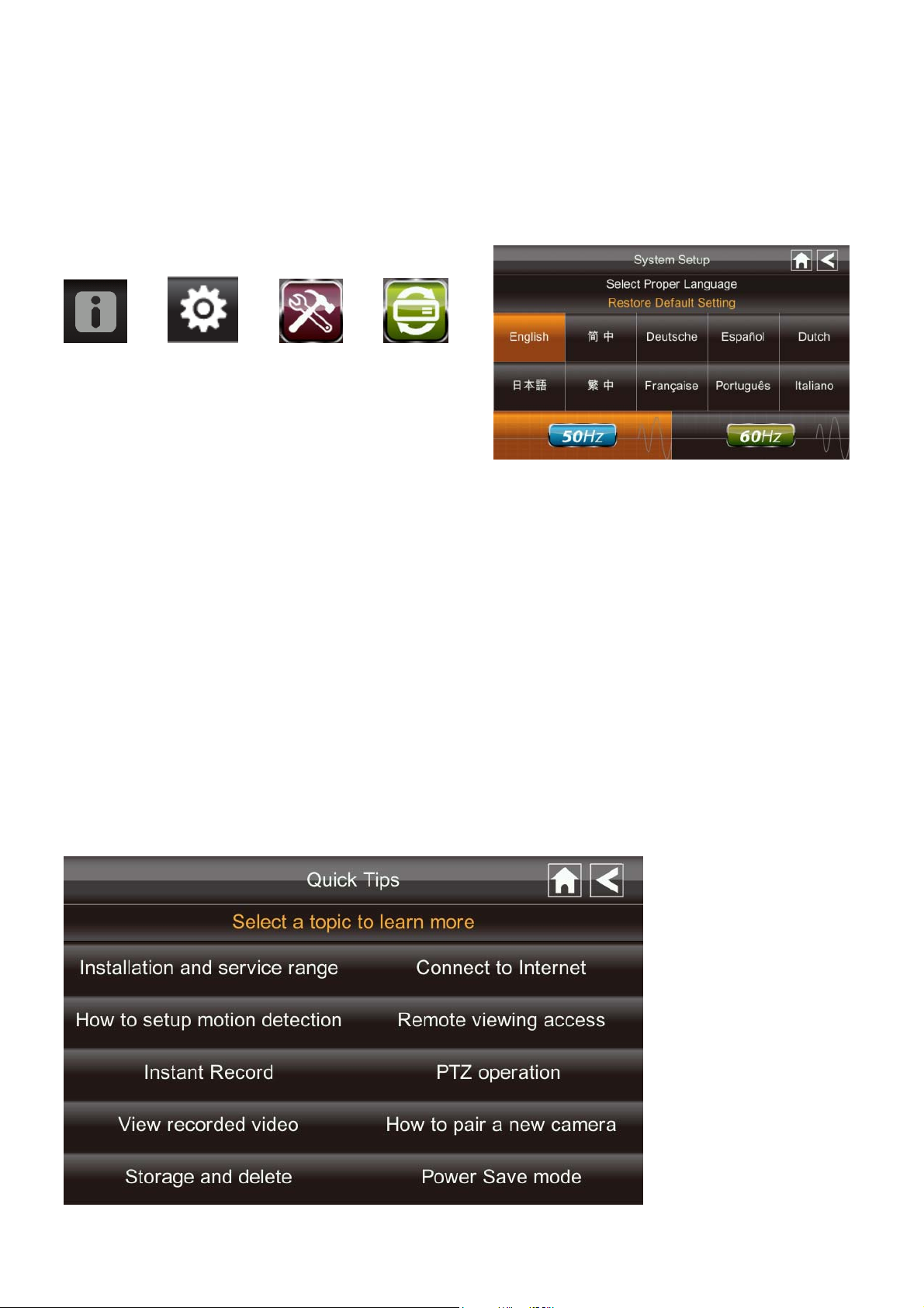
Language
English is the default language. If you change the language, all system settings default to
the original factor y settings. You will have to reenter any specialized settings.
From the pop-up menu, tap the following
icons
The screen displays:
1. Select the language required. Th e Resto re Default Settings screen displays.
2. Tap OK to continue. The system will shut down in about 5 se conds.
3. When the system restarts, it will ask you to perform the touch screen calibration.
Follow the instructions on the screen.
4. Select the frequency setting by tapping the frequency icon (50Hz /60Hz) . Make sure
the frequency setting complies with local electrical regulations.
Note: In general the freque nc y f or North America is 110-220 volt at 60 Hz.
Quick Tips
The Quick Tips screen provides additional details on important subjects of system
operation. Tap on a subject to display the information.
Page 32

REMOTE ACCESS
Overview
This Voyager Video Security System lets you view li ve video from your iPhone, iPad, or
Android smartphone or tablet. Free apps are available th rough the iT unes App Store or the
Android Market.
Up to 2 remote users can access live video at the same time as long as they have the User
ID (DID) code and security code.
Downloading Android APP
From your Android smart phone or tablet device, go to the Android Market and search for
OMGuard.
Downloading iPhone APP
From your iPhone or iPad, go to the iTunes App Store and search for OMGuard
Connecting to the Internet
The docking cradle charges your monitor as well as provides an internet connection.
When you are connected to the internet, live video will continue to displ ay on the monitor,
but the monitor's touch operation will become limited.
Monitor's touch operat ion will resume normal after disconnecting from the int ernet by
selecting Charge Only option from the pop up menu, or remove monitor from the docking
cradle.
1. Connect the AC adapter to the docking cradle.
2. Connect the RJ45 (Ethernet) cable from the back of the cradle to your primary router
(from your internet service provider).
3. Insert the monitor into the cradle. A screen asks if you want to connect to the internet
or only charge the monitor.
Page 33

4. Tap Connect. The Internet Connection Status Indicator appears on the upper left of
the Live screen indicating that the system is connected to the internet.
You can now view live video through your mobile devices.
>> While the system is connected to the internet, the LIVE screen display rate may
reduce to 2 - 3 frames per second.
5. When you connect remotely to the monitor, the Internet Connection Status Indicator
shows that remote view is in progress.
Next time you place the monitor back into the cradle, the system will automatically
connect to the internet."
Connecting to the Intranet (Home Network)
When the monitor is placed in the cradle and "charge only" is selected, you can still access
your live video from smartphone(s) or tabl et(s) as long as those devices are also connected
to the same network as the monitor. For example, your smartphone is connected to your
home network via WiFi, in this case, live video will still be displayed on the monitor as
well as on the smartphone.
Note: For this pro cedure, the AC adapter must be connected to the cradle and not to the
monitor.
Page 34

TROUBLE SHOOTING
TROUBLE SOLUTIONS
No image Screen lock may be on. Tap the Power button to unlock the
screen.
Make sure the camera is powered on.
Make sure the monitor has enough charge / connect it to
AC/DC adaptor.
Move the camera closer to the monitor; it might be out of
range or move the antenna of the receiver to obtain best
possible reception.
Poor picture quality Move the antenna of the receiver to obtain best possible
reception.
Clean the camera lens using lens cleaning cloth.
The motion sensor not
working
Increase or decrease the sensitivity of the motion sensor
(please refer to the Motion Detection section).
Check the settings on the RECORD screen.
No recording happens
although it has the
schedule set.
Unable to pair the camera
to the receiver
A white image appears at
night
LIVE screen has no icons. Screen lock may be on. Tap the Power button to unlock the
System locked up Power off the receiver and restart. If power button does not
Ensure correct DATE AND TIME has been set and the
Record Schedule setup corr e ctly.
Ensure the memory card is inserted into DVR and formatted.
Make sure the camera is powered on.
Press and release the pairing button quickly. Do not press and
hold.
Power off the receiver and restart. If power button does not
respond, use a pin to press the reset button.
The camera's infra-red LEDs shine invisible light that reflects
off surfaces such as glass will cause white light. Place the
camera on the other side of windows to improve the night
vision or place it in a well-lit area (recommend to install a
security lamp to improve lighting).
screen.
respond, use a pin to press the reset button.
Unable to use the
Windows Media Player
to play the video
clips from the SD card
The video files play with a Quicktime® player. Download
this free player from www.apple.com . You can also
download the alternative free player, VLC Media Player,
from www.videolan.org. Ensure your PC has SD card reader.
Page 35

PRODUCT SPECIFICATION
Camera Receiver
Frequency: 2.405-2.480GHZ
Transceiver
Modulation : GFSK
Sensitivity: -82DBm
Maximum channels - 4
Communication Range 500 feet in open space
LCD Monitor Resolution 800 x 480
Camera Resolution Single Camera: 480x272 / Multiple Camera: 320x240
Operating Temperature -14 ~ 122゚F
゚F
Operating Voltage DC 5V / 1A
Current Consumption 500mA (MAX) 800mA (MAX)
Night Vision 26 feet
Dimension 5.9 x 2.9 x 1.9 inches 7.3 x 5 x 1.1 inches
Battery N/A 3.7V 1800mAH (LI-ON)
Recording Time for Memory Card (32GB max)
Multiple Cameras SD Card Capacity Single Camera
(Full Screen)
(QUAD Mode)
1GB 200 Minutes 130 Minutes
2GB 400 Minutes 260 Minutes
8GB 1,600 Minutes 1,040 Minutes
16GB 3,200 Minutes 2,080 Minutes
32GB 6,400 Minutes 4,160 Minutes
Note: Single camera file recorded with video/audio; multiple camera file recorded with video only.
Battery Used In the LCD Monitor
The LCD monitor is fitted with a 3.7V 1800mAH (Li-ON) rechargeable battery pack.
If the power supply adaptor is kept connected to the monitor then the battery will begin recharging
until fully charged. The monitor can still be used if left connected to the power supply adaptor.
Note:
1. From zero
2. The rechargeable battery will maintain 80% of its efficiency within the 300 charge-discharge
cycle.
3. The rechargeable battery is not user displaceable. Do not try to change the battery or remove
the battery.
charge, the rechargeable battery takes approximately 8 hours to reach full charge.
Page 36

Page 37

techservice@asaelectronics.com
www.asaelectronics.com
Page 38

BARNVIEW1
Pantalla Táctil de 7” con DVR & Cámara
Este manual debe ser guardado para referencias futuras.
Page 39

NOTA IMPORTANTE
FAVOR DE LEER ANTES DE LA INSTALACION
Tenga cuidado cuando inst a le equipos de CCTV especialmente cuando exista una
política. Consulte la legislación local pertinente aplicable a la instalación de video
grabación/vigilanci a. El consentimiento de terceras partes puede ser requerida.
RANGO DE FUNCIONAMIENTO DE DISPOSITIVOS INALAMBRICOS
Asegúrese de que la señal recibida de la cámara inalámbrica sea la mejor posible entre
la cámara y la pantalla. De ser necesario reduzca la distancia entre la cámara y la
pantalla para mejorar el funcionamiento general del sistema. Este sistema funciona a
una frecuencia digital segura de 2.4GHz lo que reduce la interferencia con artículos
como routers inalámbricos, teléfonos inalámbricos u hornos microondas.
PRECAUCIONES SE SEGURIDAD IMPORTANTES
Daños causados por el no cumplimiento de este manual escaparan de la garantía. No
asumiremos responsabilidad al guna por daños a artículos o personas causados por el
manejo inadecuado o el no cumplimiento de las normas de seguridad. Cualquier reclamo
de garantía será nulo y escapara en cualquiera de los casos.
1. No tire, punce o desarme la cámara o pantalla.
2. Evite a la pantalla del contacto con el agua y séquese las manos antes de usarlo.
3. Nunca jale los cables de energía. Coja el enchufe para desenchufarlo de la pared.
4. Use los dispositivos con cuidado. Evite l a fuerte presión sobre la cámara & pantalla.
5. Use solo accesorios y adaptadores de Corrientes suministrados por el fabricante.
6. Revise que los cables de energía no se aplasten ni sean dañados por bordes filosos.
Declaración de cump lim ien to FC C:
Este dispositivo cumple con la Parte
15 de la reglas FCC. El
funcionamiento esta sujeto a las
siguientes condiciones:
(1) este dispositivo puede no causar interferencia
dañina, y (2) este dispositivo puede recibir
interferencia, incluyendo a quella que pueda caus ar
un funcionamiento indeseado.
(2011/65/EU) emitida por la Comisión de la
Comunidad Europea. El cumplimiento de estas
directivas implica la conformidad con las Normas
Europeas:
EMC: EN 301 489
LVD: EN 60950
Radio: EN 300 32 8
Productos con la marca CE cumplen con
la Directiva EMC (2004/108/EC);
Directiva de Bajo Voltaje (73/23/EEC);
R&TTE(1999/5/EC); Directiva ROHS
Page 40

ADVERTENCIA FCC/CE
Este equipo se ha probado y se encontró que cumple con los límites para los dispositivos
digitales Clase B, de acuerdo a la Parte 15 de la regulación FCC y ETSI(EN) 300328.
Estos límites son diseñados para proveer una protección razonable contra interferencia
dañina en instalaciones residenciales. Este equipo genera, usa y puede irradiar energía en
radiofrecuencia, y si no se instala ni se usa de manera correcta puede causar interferencia
en las comunicaciones de radio. Sin embargo, no existe garantía alguna de que la
interferencia no ocurrirá en una instala
recepción de un equipo de radio o televisión, lo que se puede determinar apagando y
encendiendo el equipo, se recomienda fuertemente que el usuario trate de corregir la
interferencia a través de las siguientes medidas:
-Reorientar o reubicar la antena de recepción.
-Mover el equipo lejos del receptor.
-Conectar el equipo a un circuito de corriente diferente al cual el receptor está
conectado.
-Consulte al proveedor o a un técnico especializado en radio/televisión por sugerencias
adicionales.
Se le a provenido de que cualquier cambio o modificación del equipo, no aprobada
expresamente por la parte responsable del cumplimiento, puede limitar su capacidad de
operar dicho equipo.
ción en particular. Si este equipo interfiere con la
DISPOSICION
Si el sistema de la cámara no funciona o no puede ser reparada, esta se
debe disponer de acuerdo a las regulaciones vigentes. Disposición de
baterías/acumuladores gastados:
¡Se requiere por ley (Ordenanza de Baterías) que devuelva todas las
baterías y acumuladores gastados! ¡La disposición de baterías /acumuladores gastados
junto con residuos domés
contienes sustancias peligrosas están marcadas con un símbolo al costado. Estos símbolos
indican que esta está prohibida de ser dispuesta junto con los residuos domésticos. Las
abreviaciones para los respectivos metales pesados son: Cd=cadmio, Hg=mercurio y
Pb=Plomo. Usted puede devolver las baterías y acumuladores gastados a los puntos de
recolección designados en su comunidad, centros de compras o en cualquier lugar donde
las baterías y acumulador es sean
cumplir con los requerimientos legales y contribuir con la protección de nuestro ambiente!
Para cumplir con las limitaciones de FCC/CE para dispositivos de clase B y para evitar la
interferencia, siga por favor las instrucciones de instalación del fabricante.
ticos comunes está prohibida! Baterías/acumuladores que
vendidas. ¡El seguir estas instrucciones le permitirán
Page 41

El “ID del Dispositivo” y la “Contraseña” son provistos en la etiqueta al
reverse de la Pantalla LCD (detrás del soporte).
El “ID del Dispositivo” y la “Contraseña” se necesitan para la visión remota..
Para propósitos de seguridad, se recomienda al usuario copiar el “ID del
Dispositivo” y la “Contraseña” en el manual de usuario y retirar la etiqueta que
contiene el “ID del Dispositivo” y la “Contraseña”.
Por favor guarde este manual en un lugar seguro para proteger el ID de
dispositivo y la contraseña para una futura referencia.
Siempre sea discreto al instalar un equipo de vigilancia CCTV, especialmente
cuando exista una política. Cumpla con las regulaciones locales aplicables para
la instalación legal de una video grabación/vigilancia. El consentimiento de
terceras partes pues ser requerido.
REQUERIMIENTOS PARA LA VISION REMOTA
Dispositivo Compatible
- iPhone / iPad / iPod Touch c/ iOS 5.0.1 o superior
- Android smartphone / tabl et v2.3X o superior"
Nota: No compatible para Windows o Smartphones Blackberry
Velocidad mínima rec o m e ndada de carga de internet
Velocidad de carga de 512Kbps (o banda ancha) para tener hasta un promedio de 2FPS se
velocidad e visión. La velocidad promedio de visión depender á de otras restricciones de
su ISP (proveedor de servicio de internet).
Page 42

CONTENIDO
Imagen Contenidos EA
1 EA
Video cámara inalámbrica con pedestal de mont aje
1 EA
Pantalla táctil LCD de 7” con soporte y batería
interna recargable de 2 horas de duración.
Adaptador de corriente de 5V para la
cámara/pantalla
2 EA
2 EA
Antenas 5dBi
1 EA
Cable de antena de 9.5 pies & cua dro de montaje
para la pantalla
1 EA
Cable de antena de 29. 5 pies & cuadro de mont aje
para la cámara
1 EA
Antena 3dBi (Antena corta para la pantalla,
necesaria para uso portátil)
1 EA
Cable pare internet
1 EA
Artículos de montaje
1 EA
Manual de Usuario
Page 43

CONSEJOS DE SEGURIDAD E INSTALACION
Pantalla Táctil LCD
Manténgala alejada de Fuentes de calor y altas temperaturas
Evite la exposición directa al sol
Evite lugares húme dos
Evite vibraciones
Instálela en un ambiente ventilado
Compatible con tarjeta SD de hasta 32GB SD (no incluida)
Notas de Instalación
Siga siempre las recomendaciones del fabricante cuando use herramientas eléctricas,
bancas, escaleras, etc. y use equipo de protección (ej.: gafas de seguridad y guantes)
cuando taladre agujeros, etc.
Cuanto use escaleras asegúrese que este ubicada en una superfici e firme y estable en un
ángulo adecuadamente seguro. Revise cables de electricidad escondidos o tuberías de
agua antes de taladras cualquie r agujero. Por si la dudas use un cabe/tubo de ubicación. Se
recomienda evitar que la cámara este expuesta a condiciones de clima extremos (ej.: bajo
una gotera). Después de taladrar cualqui er agujero en una pared externa, asegúrese de que
el agujero sea sellado para prevenir cualquier fuga.
Para prevenir un incendio o riesgo de shock eléctrico, no intente abrir el equipo cuando la
cámara este expuesta a condiciones húmedas. No e xponga cable o conexión alguna al
clima. Si se realiza la conexión o cableado en exteri ores use un medio adecuado de
protección para aisl ar el equipo de las condiciones ambientales.
No existe ninguna parte que el usuario pueda arre glar. Déjelo en manos del pers onal de
servicio calificado.
Instalación de Cámara
Evite que la ubicación de la cámara exponga directamente a la misma a la luz solar ya que
disminuirá la calidad de visión de imagen.
Evite ubicar la lente de la cámara directamente a través de un cristal claro ya que las LEDs
de visión nocturna proporcionaran una imagen borrosa en la noche.
Evite ubicar la cámara directamente hacia cualquier arbusto, ramas de árboles u objetos en
movimiento que se pueden mover naturalmente por acción del viento . Esto debido a que si
usted necesita usar la característica de grabación de detección de movimiento, el software
podrá grabar innecesariamente.
Page 44

NOTA: La cámara tiene un rango de operación RF a campo abierto de hasta 500’.
Instalación de la Cámara
Desajuste el tornillo mariposa
Asegure la cámara en una superficie estable
Ajuste a un ángulo de visión
apropiado, luego asegure el brazo con
el tornillo mariposa.
Page 45

Instalación de la Antena
Antena 3dBi
Antena 5dBi
Configurar el Canal de la Cámara (opcional)
La cámara inalámbrica viene predeterminada en canal 1.
La pantalla es compatible con hasta 4 cámaras. Siga los pasos siguientes en la sección
Configuración de Cámara para configurar o cambiar el canal de la pantalla de la cámara.
Si usted agrega una cámara adicional a la pantalla suministrada en este sistema asegúrese
de configurar un canal diferente a la primera cámara existente.
Unión de la Cámara con el Receptor (opcional)
Siga los pasos en la sección Configuración de Cámara o cambien el canal de la cámara. Si
usted agrega otra cámara a la pantalla suministrada en este sistema asegúrese de
configurar un canal diferente a la primera cámara existente.
Page 46

Conecte el adaptador CA/CC al
tomacorriente más cercano.
Nota:
Si la cámara está ubicada a 3-5 pies de la pantalla y el volumen de la cámara esta
encendido, usted podrá oír un sonido de zumbido en la pantalla lo cual es el feedback
capturado por el micrófono. En este caso ubique la cámara más alejada de la pantalla para
evitar el r uido.
Si la conexión a la corriente de la cámara está en exteriores, asegúrese de que esté
debidamente prot e gida.
Para más detalles en la instalación del cuadro de la cámara y el fijad o , favor de referirse a
la sección Instalación de la Cámara.
Configuración de la Pantalla
1. Deslice el soporte, extienda la antena, conecte el adaptador CA/CC a la entrada al
lado de la pantalla.
To Wireless Camera
Page 47

2. Presione y mantenga el botón POWER en la parte superior de la pantalla por 5-6
segundos para encenderla.
3. El receptor muestra la Pantalla de Bienvenida por unos segundos y luego muestra la
visión en VIVO.
4. La tarjeta SD debe estar insertada en la ranura correspondiente a lado de la pantalla.
Nota: La pantalla permanece oscura hasta que la cámara se haya encendido.
La pantalla tiene una batería recargable que puede funcio nar por hasta 2 horas cua ndo esté
completamente c argada (c/la función de Ahorro de Energía activada). La pa ntalla puede
ser llevada a cualquier punto dentro del rango de funcionamiento de la cámara, pero sebe
ser usada en un ambiente seco ya que no es a prueba de agua.
Operación del Sistema
Favor de referirse a la sección de Operación del Sistema para la Configuración de Cá mar a,
Sistema y Grabación.
Acceso Remoto
Puede realizarse via iPhone / iPad / iPod Touch c/iOS 5.0.1 o superior, Android
smartphone / tablet v2.3X o superior conectado a internet 3G/WiFi.
Para un dispositivo Android
Favor de referirse a la sección Descargar APP para Android.
Para un iPhone, iPad1, iPad2, Nuevo iPad
Favor de referirse a la sección Descargar una APP para iPhone.
Nota:
La pantalla debe estar ubicada en el soporte para permitir la visión remota.
Si se le retira del soporte, la cámara solo podrá ser vist a en la pantalla.
Page 48

CONOCIENDO LA PANTALLA
SIGNIFICADO DE LUCES
Luz Estado Significado
Enc. (Rojo) La cámara está encendida.
Estado de energía
Estado de conexión
Apagado La cámara está apagada.
Parpadeando La cámara está en modo de unión.
Enc. (Verde) La cámara está conectada al receptor.
Apagado La cámara esta en standby.
Page 49

INTRODUCCION AL SISTEMA
Su software del sistema de p a ntalla funciona a través de series de pantallas que le
permiten grupos de operacione s. Por ejemplo, cuando selecciona el icono de cámara en el
menú emergente, podrá configurar como usted quiere que la pantalla principal “Pantalla
en Vivo” muestre las imagen de las cámaras conectadas. Puede buscar entre cámaras,
mostrar todas las cámaras en una sola pantalla (Vista en cuadros), o solo mostrar una
cámara especifica.
La pantalla en Vivo le permite ver las transmisiones de la cámara. También le permite
configurar su pantalla y hacer ajustes en ella. Los iconos en la pantalla le permiten
supervisar el estado de energía y de la cámara.
Page 50

ICONO SIGNIFICADO DEL ICONO
Selecciona como quiere que la pantalla en Vivo muestre la imagen de la
cámara:
Modo de Cámara
Busque entre cámaras (5 segundos)
Vista en cuadros (todas las cámaras unidas)
Vista completa (muestra 1 cámara en la pantalla)
Volumen
Configuración del
Sistema
Capacidad SD Indica la capacidad restante de memoria.
Capacidad de
Batería
Número de Cámara
Estado Grabación
Conectando a
Internet
Conectado a
Internet
Ajusta el nivel del volumen.
Accede a la operación del software del sistema, pagina de configuración
o eventos grabados.
Muestra la capacidad de bacteria. El grafico muestra la batería casi llena.
Muestra el número de cámara y la fuerza de la señal en las líneas a la
izquierda del número.
Seleccione para iniciar o detener la grabación de esa cámara.
• Encendida – Sin grabar • Flashing - Grabando
Conectando su sistema a internet.
Conecta su sistema a internet.
Conectado a
Intranet
Visión Remota Indica que la visión remota está en proceso.
Movimiento
Programado El sistema indica que una grabación programada está en progreso.
Pestaña de Menú
Emergente
Inidicador de falta
de Tarjeta SD
Acercamiento
Conecta su sistema a intranet.
El sistema indica que la grabación de detección de movimiento está en
progreso.
Abre y cierra el menú emergente.
Se muestra en rojo cuando la tarjera SD no esta o esta dañada.
Acercamiento o alejamiento de una sección en particular del video en
vivo.
Page 51

Pantalla en Vivo
La pantalla en Vivo muestra 2 vistas- Vista en Cuadros o Vista Completa. Vista en
Cuadros muestra la imágenes en 4 cuadrantes (solo muestra las cámaras que están
encendidas). Seleccione un cuadrante para mostrar la vista de una sola cámara/vista
completa. Seleccione esa imagen nuevamente para volver a la Vista en Cuadros.
Característica de Acercamiento
Para acercar una área en particular,
1. En la vista completa seleccione para activar el modo de acercamiento.
2. Seleccione el área para ver el acercamiento en la pantalla.
Grabar un Video en Vivo
1. En la pantalla en Vivo seleccione para que la cámara que empiece a grabar.
2. Seleccione de Nuevo para detener la grabación.
Usted puede grabar con todas las cámaras al mismo tiempo. Con la grabación manual,
cada sesión de grabación (video por cámara) es de 2 minutos.
Page 52

Reproducir un Video Grabado
En el menú emergente seleccione los
siguientes iconos
La pantalla Lista de Grabación
muestra:
1. Seleccione el día resaltado conteniendo la grabación que desea ver.
La pantalla Lista de Grabaciones mostrara las grabaciones de ese día en una carpeta.
Si usted selecciona un día que no está resaltado, se mostrara una carpeta sin
grabaciones.
2. Seleccione la grabación que dese ver. Se muestra en la pantalla.
3. Seleccione en cualquier área de la pantalla que no tenga iconos de control para
mostrar la barra de progreso de reproducción. Seleccione esa área nuevamente para
cerrarlo.
4. Mientras la reproducción en prog reso sea visible, podrá rápidamente
avanzar/retroceder arrastrando la barra de reproducción.
5. Cuando la reproducción finali ce , seleccione
Grabaciones.
o para regresar a la Lista de
Page 53

MENU DE SISTEMA
Desde el menú emergente seleccione los
siguientes iconos
La Pantalla Principal muestra:
El MENU DEL SISTEMA resalta la opción de Configuración de la Cámara por
defecto.
Pantalla PrincipalSub Pantalla Función
Configuración de
Config. Cámara Une nuevas cámaras al receptor
Cámara
Configuración de
Grabador
Configuración de
Red
Alarma
Configuración de
Sistema
Cámara Encendida Hace las cámaras visibles en la pantalla.
Brillo Aclara u oscurece el video de esa cámara.
Detección de
Movimiento
Grabación ProgramadaConfigura
Configuración de
Internet
Código de Seguridad
Información de Red
Periodo Configura la duración deConfiguración de
Melodía Selecciona la melodía de la alarma.
Ahorro de Energía Apaga la LCD temporalmente después de 2
Auto-Bloqueo de
Pantalla
Graba cuando algo se mueve frente a la
cámara. Continúa grabando por 2 minutos.
un programa para grabación de
tiempo y duración predeterm
Selecciona el tipo de conexión de internet a ser
usada.
Configura un código de seguridad para el
acceso remoto.
Muestra la información de
único DID del receptor.
minutos de inactividad
Bloquea la pantalla de
desbloqueo.
toda actividad hasta el
inada.
su red y el numero
l sonido de la alarma.
Tiempo Configura el tiempo en incrementos de 12 h..
Guarda Formato Formatea/borra la tarjeta SD.
Actualización Sistema Actualiza el firmware del receptor.
Predeterminado Muestra las predeterm
Consejos Rápidos N/A Muestra una lista de 10 preguntas comunes.
inación del sistema.
Page 54

OPERACION DEL SISTEMA
Configuración de Pantalla de
Cámara
Seleccione configuración de camera.
Esta pantalla debe mostrar:
Unión de Cámara
Su cámara está unida a la pantalla en el canal 1 predeterminado.
Para agregar nueva cámara al su sistema debe unirlas a diferentes canales.
En el menú emergente, seleccione los
siguientes iconos
La Pantalla Principal muestra:
1. Seleccione la imagen de la cámara que desea unir. Un icono de procesamiento se
mostrara por 60 segundos.
2. Presione y libere el botón de Unión en el cable de energía de la cámara (favor de
referirse a la sección Conociendo la Pantalla y Cámara). El sistema indicara que la
unión ha sido exitosa cuando la unión se complete.
3. El sistema automáticamente ajustara Cámara Encendida en la pantalla.
Page 55

Activación de Cámara
Cuando agregue una cámara a su sistema, el sistema encenderá automáticamente la
cámara.
En el menú emergente, seleccione los
siguientes iconos
La pantalla muestra:
Una X indica que la c ámara está APAGADA, un check indica ENCENDIDO. Seleccione
la capara para ENCENDERLA o APAGARLA.
Brillo
En el menú emergente, seleccione los
siguientes iconos
The screen displays:
Seleccione la cámara para cambiar el nivel de brillo. La predeterminación de brillo es 0 y
el rango va de -2 a 2..
Page 56

Pantalla de Configuración de Grabación
Detección de Movimiento
En el menú emergente, seleccione los
siguientes iconos
La pantalla muestra:
Seleccione las cámaras para establecer la sensibilidad en Apagado, Bajo o Alto.
Defecto = bajo. La pantalla volverá la pantalla de Detección de Modo después de 10
segundos o cuando presione el icono Atrás.
Email de Alerta
El sistema puede notificarle cuando detecta movimiento de cualquier cámara enviándole
un email de alerta. El email de alerta contiene información como el tiempo en el que el
movimiento fue detectado y por qué cámara. En orden de activar la función de Email de
Alerta debe ingresar la dirección de correo remitente y destin
Recomendamos fuertemente que use Gmail para establecer el servidor de salida de
email.
o.
Page 57

El servidor de email de salida (servidor SMTP) es responsable de enviar la notificación de
email para informar a los usuarios cuando el sistema detecto movimiento en cualquier
cámara (Detección de Movimiento debe estar activada).
El servidor de de ingreso de email (Email Para) recibe la notificación de email enviada
desde el servidor SMTP. El usuario debe poder recibir el email en una PC con Windows o
dispositivos móviles (como un iPhone, iPad o Smartphone Android o tablet) para recibir
emails de alerta desde el sistema.
Cuando reciba el email
Smartphone Android o Tablet Android a través de aplicaciones. Aplicaciones gratis están
disponibles a través de la tienda iTunes App o la Tienda Android.
de alerta, puede ver el video en vivo desde un iPhone, iPad,
En el menú emergente, seleccione los
siguientes iconos conforme aparecen en la
pantalla:
La pantalla muestra:
1. Seleccione Activar, para activar el Email de Alerta o Desactivar para desactivarlo.
2. Seleccione el campo de Servidor SMTP. La pantalla muestra un teclado.
3. Ingrese su servidor SMTP de salida de email (ejemplo: johndoe@gmail.com). Usted
puede cambiar el teclado de caracteres alfabéticos a números/símbolos y luego de
nuevo seleccionado el campo a la izquierda de la barra espaciadora. Seleccione
Page 58

Regresar. La pantalla de Email de Alerta se muestra de nuevo.
4. Repita el paso previo para el campo Contraseña. Seleccione Regresar. La contraseña
ingresada aquí debe ser la misma para la cuenta de salida de email.
5. Repita el Paso 3 para el campo Email Para. Solo una cuenta de email será aceptada
por el sistema. La cuenta de ingreso de email puede ser diferente de la cuenta de
salida.
6. Seleccione OK para guardar las configuraciones, luego seleccione
la pantalla previa.
Si está usando Gmail como servidor SMTP de salida, revise SSL y use la información
de la tabla siguiente:
Para Gmail
Servidor SMTP Smtp.gmail.com Ingrese esto.
Puerto SMTP 465 Ingrese esto.
Usuario XXXX@gmail.com Ingrese su dirección complete
gmail, incluyendo @gmail.com.
Contraseña XXXXXXXXXX Ingrese su contraseña para esta
cuenta gmail.
Email para XXXX@gmail.com Ingrese la dirección de email
donde desea que la alerta sea
enviada.
para regresar a
Grabación Programada
Hasta 5 sesiones de grabación programada están disponibles en un solo día. Usted está
limitado por la capacidad de la tarjeta SD para la duración total de la grabación. Estas
grabaciones deben empezar en un periodo simple de 24 horas. No se pueden pasar a un
siguiente día.
En el menú emergente, seleccione los
siguientes iconos
La pantalla de Grabación Programada
muestra:
1. Seleccione el número de cámara/canal que desea grabar (1-4). Se pueden seleccionar
varias cámaras.
Page 59

2. Seleccione el tiempo de inicio y finalización de grabación. Seleccione los recuadros
de hora y minutos por separado y use las flechas ARRIBA y ABAJO para
desplazarse entre los valores.
3. Seleccione el bloque AM/P M par a desplazarse entre ell os.
4. Seleccione en el recuadro en blanco de FECHA. Se muestra el Calendario de
Grabación Programada.
5. Seleccione la fecha en la cual desea grabar. Se muestra en la pantalla previa.
6. Configure la grabación y seleccione Guardar. Puede seleccionar otra sesión de
grabación a ser programada.
Borrar una Grabación Programada
1. Acceda a la pantalla de Grabación Programada.
2. Seleccione la grabación programada que desea borrar (1-5). La pantalla muestra la
configuración para ese programa.
3. Seleccione BORRAR. La pantalla se resetea a los valores por defecto para esa ranura
de grabación.
Pantalla de Configuración de Red
La pantalla de Configuración de Red le permite selecciona r su tipo de i nternet y establecer
un código de seguridad. Usted puede también ver la configur ación por defecto del
sistema.
En el menú emergente seleccione los
siguientes iconos
La pantalla de Configuración de Red
muestra:
Page 60

Configuración de Internet
1. Seleccione el ícono de Configuración de Internet para mostrar la pantalla de
Configuración de Internet.
2. Seleccione y llene los campos requeridos. Seleccione OK.
3. Seleccione OK en la solicitud de reinicio del sistema. La pantalla de Configuración de
Red se muestra.
Código de Seguridad
Establezca su código de seguridad para limitar quien puede acceder al sistema desde una
ubicación remota .
Page 61
1. Seleccione el icono de Código de Seguridad para mostrar la pantalla de Código de
Seguridad.
2. Su usted ha ingresado previamente un código, la pantalla mostrara su código actual.
3. Seleccione el campo para cambiar el código, se muestra un teclado.
4. Ingrese su código de seguridad.
5. Seleccione OK. El sistema volverá a la pantalla de Conf iguración de Red.
Nota: El código de seguridad debe ser ingresado para ganar acceso remoto. Para
proteger su privacidad, favor asegure de cambiar l a c ontraseña por defecto 123456 a su
código de seguridad personal.
Información de Red
1. Seleccione el icono de Información de Red para mostrar la pantalla de Información de
Red.
Page 62

2. Seleccione la fleche REGRES AR para retornar a la pantalla previa.
Nota:
El DID es un código único específico para su pantalla y es requerida para ganar acceso
remoto a su cámara en la internet.
La información en la configuración de DHCP est á asi gnada a su pantalla desde su
router.
Pantalla de Configuración de Alarma
En la pantalla de Configuración de Alarma puede:
Establecer la duración del sonido de la alarma
Seleccion a r la melodía de la alarma.
Page 63

Periodo
Esta selección le permite selec cionar la duración de la alarma/sirena para la Al arma y
Temporizador de Reloj.
1. Seleccionar Periodo. Se muestra la pantalla de Establecer la Duración de la Sirena.
2. Seleccione la duraci ón requerida de la alar ma
3. Seleccione la fleche REGRES AR para retornar a la pantalla previa.
Melodía
Esta seleccione le permite selecciona la melodía para la sirena.
1. Seleccione Melodía. Se muestra la pantalla de Cambio de Melodía de Sirena.
2. Seleccione la melodía requerida
3. Sele c cione la fleche REGRESAR para retornar a la pantalla pr evia
Page 64

Pantalla de Configuración de Sistema
Ahorro de Energía
En el modo de Ahorro de Energía la pantalla se apagara después de 2 minutos de
inactividad. Presione el botón Power una vez para reactivar la pantalla.
Si inicia un evento de detección de movimiento o una grabación programada, la LCD se
enciende automáticamente.
1. Seleccione Activar Ahorro de Energía para activar lo. El valor por defecto es
apagado.
2. Un check aparece en su selección.
3. Seleccione la fleche REGRESAR para retornar a la pantalla previa.
Page 65

Auto-bloqueo de Pantalla
En el modo de Auto-bloqueo, la pantalla entrara al modo de bloqueo de pantalla después
de un periodo de inactividad de 2 minutos. El Auto-bloque o desactiva la p antalla táctil y
retira los iconos de la pantalla.
1. Seleccionar el Auto- b loqueo de Pantalla
2. Seleccione su opción; se muestra un check.
3. Seleccione la fleche REGRESAR para r etornar a la pantalla pre via.
Nota: Desde la pantalla en Vivo, seleccione al botón Power una vez para
desbloquear la pantalla y retornar a la operación normal de pantalla táctil.
Tiempo
La pantalla Tiempo le permite establecer alarmas de reloj, establecer el tiempo del sistema
y un temporizador.
En el menú emergente, seleccione los
siguientes iconos
La pantalla muestras:
Page 66

Alarma de Reloj
Esta característica funciona como una alarma de reloj independiente. Esta no afecta el
funcionamiento del video en vivo o de la grabación de video.
1. Seleccione
2. Seleccione el botón de alarma (de 5 totales).
3. Seleccione el bloque hora/minutos y lue go l as flechas ARRIBA/ABAJO para
establecer el tiempo.
4. Seleccione AM/PM para desplazarse entre las dosis.
5. Seleccione GUARDAR y luego regresar.
par a mostrar la pantalla de Alarma de Reloj.
Configuración de Tiempo
Esta pantalla contiene campos para establecer el Mes, el Día, el Año, la Hora, Minuto y
AM/PM.
1. Seleccione
para mostrar la pantalla de Configuración de Tiempo.
Page 67

2. Seleccione cada campo para establecerlo. Las flechas ARRIBA/ABAJO cambian el
campo. Use ARRIBA/ABAJO para establecer el campo
3. Seleccione el bloque AM/PM para cambiar entre ambos.
4. Seleccione GUARDAR cuando termine.
Temporizador
Esta característica fu nc ión como un reloj de alarma independiente. No afecta el
funcionamiento de video en vivo o grabación de video.
1. Seleccione
2. Seleccione cada campo para establecerlo. Use ARRIBA/ABAJO para establecer el
campo.
3. Seleccione INICIO para empezar el tiempo. Cuando el tiempo alcance 00:00, una
alarma suena hasta que seleccione OK.
Para mostrar la pantalla de Configuración de Tiempo.
Page 68

Formatear Almacenamiento
Cuando use una tarjeta SD, se recomienda fuertemente que formatee la tarjeta usando
estos procedimientos. Formatear cualquier tarjeta SD borra los archivos en la tarjeta.
En el menú emergente seleccione los
siguientes iconos
La pantalla de Formatear
almacenamiento se muestra:
1. Seleccione INICIO; se muestra una declaración de advertencia.
2. Seleccione OK para proceder a formatear el almacenamiento o seleccione
CANCELAR para desconti nua r .
3. El sistema indicara éxito o fallo.
Actualización del Sistema
Para actualizar el firmware desde el sitio web del proveedor usted debe descargarlo y
almacenarlo en el directorio raíz de la tarjeta SD.
En el menú emergente seleccione los
siguientes iconos
La pantalla muestra:
Presione el botón Inicio para actualizar el firmware.
Page 69

Idioma
Inglés es el idioma por defecto. Si usted cambia el idioma, todas las configuraciones del
sistema se predeterminaran a las configuraciones originales de fábrica. Usted tendrá que
reingresar cualquier configuración especializada.
En el menú emergente seleccione los
siguientes iconos
La pantalla muestra:
1. Seleccione el idioma requerido. Se muestra la pantalla de Reestablecer las
Configuraciones por Defecto.
2. Seleccione OK para continuar. El sistema se apagara por 5 segundos.
3. Cuando el sistema se reinicie, este le solicitara realizar una calibración de la pantalla
táctil. Siga las instrucciones en la pantalla.
4. Seleccione la configuración de frecuencia seleccionando el icono de frecuencia
(50Hz/60Hz). Asegúrese que la configuración de frecuencia cumpla con las
regulaciones eléctricas locales.
Nota: En general, la fre
cuencia de Norte América es 110-220 voltios a 60 Hz.
Consejos Rápidos
La pantalla de Consejos Rápidos proporciona detalles adicionales en temas importantes
del funcionamiento del sistema. Seleccione un tema para mostrar la información.
Page 70

ACCESO REMOTO
Resumen
El Sistema de Seguridad del Video Voyager le permite ver video en vivo en su iPhone,
iPad, o smartphone o Tablet Androir. Aplicaciones gratis están disponibles a través de la
tienda de aplicaciones iTunes o la tienda Android.
Hasta 2 usuarios remotos pueden acceder al video en vivo al mismo tiempo al tener el
código de ID (DID) de Usuario y el código de seguridad.
Descargar una APP Android
Desde su dispositivo Android, vaya a la Tienda Android y busque a OMGuard.
Descargar una APP iPhone
Desde su iPhone o iPad, vaya a la Tienda iTunes App y busque a OMGuard
Conectar a Internet
El soporte carga su pantalla así como también proporciona una conexión a internet.
Cuando usted está conectado a internet, el video en vivo continuara mostrándose en la
pantalla, pero el funcionamiento táctil de la pantalla será limitado.
El funcionamiento táctil de la pantalla volverá a la normalidad después desconectarla del
internet seleccionando la opción Solo Cambiar en el menú emergente o al retirar la
pantalla del soporte.
1. Conecte el adaptador CA al soporte.
2. Conecte el cable RJ45 (Ethernet) desde la parte posterior de la pantalla a su router
principal (de su proveedor de servicio de internet).
3. Inserte la pantalla en el soporte. La pantalla le preguntará si desea conectarse a
internet o solo desea cargar la pantalla.
Page 71

5
4. Seleccione Conectar. El Indicador del Estado de Conexión de Internet aparece en la
parte superior izquierda de la pantalla en Vivo indicando que el sistema está
conectado a internet.
Usted puede ahora ver video en vivo a través de sus dispositivos móviles.
>> Cuando el sistema está conectado a internet, la pantalla en VIVO puede reducirse
a 2-3 cuadros por Segundo.
5. Cuando se conecta remotamente a la pantalla, el Indicador del Estado de Conexión
de Internet muestra que la visión remota está en progreso.
La próxima vez que coloque la pantalla en el soporte, el sistema se conectara
automáticamente a internet."
Conectar a Intranet (Red Doméstica)
Cuando la pantalla se coloca en el soporte y se selecciona “solo cargar”, usted aún puede
acceder al video en vivo desde su smartphone o tablet mientras que esos dispositivos estén
también conectados a la mi sma red que la pantalla. Por ejemplo, si su Smart p hone e sta
conectado a su red doméstica vía WiFi, en este caso, el video en vivo será aun mostrado
en la pantalla así como en el Smartphone..
Nota: Para este procedimiento, el adaptador CA debe estar conectado al soporte y no a la
pantalla.
Page 72

SOLUCIONADOR DE PROBLEMAS
PROBLEMA SOLUCIONES
No hay imagen El bloqueo de pantalla puede estar activado. Seleccione el
botón Power para desbloquear la pantalla.
Asegúrese de que la cámar a este encendida.
Asegúrese de que la pantalla tenga suficiente carga/conéctela
al adaptador CA/CC.
Mueva la cámara cerca a la pantalla, puede estar fuera de
alcance o mueva la antena del receptor para obtener la mejor
recepción posible.
Pobre calidad de imagen Mueva la antena del receptor para obtener la mejor recepción
posible.
Limpie la lente de la cámara usando un paño limpiador.
El sensor de movimiento
no funciona
Aumente o disminuya la se nsibilidad del sensor de
movimiento (favor referirse a la sección Detección de
Movimiento).
Revise la configuración en la pant alla GRABACION.
No graba a pesar de
haberla programado
Imposible unir la cámara
con el receptor
Aparece una imagen
blanca en la noche
La pantalla en VIVO no
tiene iconos.
Sistema bloqueado Apague el receptor y reinicie. Si el botón power no responde,
Asegúrese de que haya estableci do la FECHA Y HORA
correcta en la Grabación Programada.
Asegúrese que la memoria este insertada en el DVR y
formateada.
Asegúrese de que la cámar a este encendida.
Presione y libere al botón de unión rápidamente. No presione
y mantenga.
Apague el receptor y reinicie. Si el botón power no responde,
use un pin para presionar el botón reset.
Los LEDs infrarrojos de la cámara que emiten luz invisible y
que reflejan en superficie como video causar a n luz blanca.
Ubique la cámara lejos de ventanas par a mejorar la visión
nocturna o ubíquela en un área bien iluminada (se recomienda
instalar una lámpara de seguridad a mejorar la iluminación)
El bloqueo de pantalla puede estar activado. Seleccione el
botón Power para desbloquear la pantalla.
use a pin para presionar el botón reset.
Imposible usar Windows
Media Player para
reproducir clips de la
tarjeta SD
Los videos se reproducen con Quicktime®. Descárguelo
gratis en www.apple.com . También puede descargar gratis
VLC Media Player, en www.videolan.org. Asegúrese que su
PC tena un lector de tarjeta SD.
Page 73
ESPECIFICACION DE PRODUCTO
Cámara Receptor
Frecuencia: 2.405-2.480GHZ
Transceptor
Canales máximos - 4
Rango de Comunicación 500 pies en lugares abiertos
Resolución Pantalla LCD
Resolución Cámara Cámara Única: 480x272 / Cámara Múltiple: 320x240
Temperatura de
Funcionamiento
Voltaje de
Funcionamiento
Consumo Actual 500mA (MAX) 800mA (MAX)
Visión Nocturna 26 pies
Dimensiones 5.9 x 2.9 x 1.9 pulg. 7.3 x 5 x 1.1 pulg.
Batería N/A 3.7V 1800mAH (LI-ON)
Modulación : GFSK
Sensibilidad: -82DBm
800 x 480
-14
゚F ~ 122゚F
CC 5V / 1A
Tiempo de Grabación para Tarjeta de Memoria (32GB max)
Capacidad de Tarjeta SD Cámara Única
(Pantalla Completa)
1GB 200 Minutos 130 Minutos
2GB 400 Minutos 260 Minutos
8GB 1,600 Minutos 1,040 Minutos
16GB 3,200 Minutos 2,080 Minutos
32GB 6,400 Minutos 4,160 Minutos
Nota: Archivo de cámara única grabado con video/audio; archive de cámaras múltiples grabados solo con video.
Cámaras Múltiples
(Modo Cuadricula)
Page 74

Batería Usada en la Pantalla LCD
La pantalla LCD esta provista con un pack de una bacteria recargable de 3.7V 1800mAH (Li-ON).
Si el adaptador de suministro de energía se mantiene conectado a la pantalla entonces la batería se
empezara a cargar hasta que esté completamente cargado. La pantalla puede ser usada también
conectada al adaptador de suministro de energía.
Nota:
1. Desde la carga cero, la batería recargable demora alrededor de 8 horas para alcanzar la carga
completa.
2. La batería recargable mantendrá el 80% de eficiencia dentro de los primeros 300 ciclos de
carga y descarga.
3. La bacteria recargable no puede ser removida por el usuario. No intente cambiar o sacar la
batería.
Page 75

Page 76

techservice@asaelectronics.com
www.asaelectronics.com
Page 77
BARNVIEW1
Moniteur Écran Tactil e Quad 7 " L CD avec Magn étoscope
Numérique et Appareil Photo
Ce manuel devrait être conservé pour future référence
Page 78

AVIS IMPORTANT
S'IL VOUS PLAÎT VEUILLEZ LIRE AVANT L'INSTALLATION
Toujours faire preuve de discrétion lors de l'installation d'équipements de
vidéosurveillance, surtout quand il y a une politi que de perception. Renseignez-vous
sur les réglementations locales applicables à l'installation légale de l'enregistrement
/surveillance vidéo. Le consentement du tiers peut être nécessaire.
PLAGE DE FONCTIONNEMENT DES APPAREILS SANS FIL
S'assurer que la réception du signal vu de la caméra sans fil est la meilleure réception
possible entre la (les) caméra (s) et le moniteur. Si nécessaire, réduire la distance
entre la (les) caméra (s) et le moniteur afin d'améliorer les performances globales du
système. Ce système fonctionne sur une fréquence numérique sécurisée de 2,4 GHz
qui réduit les interférences de produits tels que les routeurs sans fil, téléphones sans
fil, ou des fours à micro-ondes.
MESURES DE SÉCURITÉ IMPORTANTES
Les dommages causés par le non-respect de ce mode d'emploi annulent la garantie. Nous
n'assumons aucune responsabilité pour des dommages matériels ou corporels causés par
une mauvaise manipulation ou le non-respect des consignes de sécurité. Toute demande de
garantie sera nulle et non avenue dans de tels cas.
1. Ne laissez pas tomber, percez ou démontez la caméra ou le moniteur.
2. Moniteur- évitez tout contact avec de l'eau et séchez les mains avant de l'utiliser.
3. Ne jamais tirer sur les cordons d'alimentation. Utilisez la prise pour le débrancher de
la prise murale.
4. Utilisez les dispositifs avec soin. Evitez d'appuyer fort sur la caméra et le moniteur.
5. Utilisez uniquement les accessoires et adaptateurs d'alimentation fournis par le
fabricant.
6. Vérifiez que les câbles d'alimentation ne soient pas écrasés ou endommagés par des
bords tranchants.
Page 79

Déclaration de conformité FCC: Cet
appareil est conform e à la pa rtie 15 des
règles de la FCC. Le fonction nement
est soumis aux deux conditions
suivantes:
(1) ce dispositif ne doit pas causer d'interférences
nuisibles, et (2) cet appareil doit accepter toute
interférence reçue, y compris les interférences
pouvant entraîner un fonctionnement indésirable.
directive ROHS
(2011/65/UE) délivré par la Commission de la
Communauté européenne. La conformité à ces
directives implique la conformité aux normes
européennes suivantes:
EMC: EN 301 489
LVD: EN 60950
Radio: EN 300 32 8
Produits avec marquage CE sont
conformes à la directive CEM
(2004/108/CE); Directive Basse Tension
(73/23/C EE ), R & TTE (19 99 /5 /C E), la
AVERTISSEMENT FCC / CE
Cet équipement a été testé et s'est avéré conforme aux limites d'un appareil numérique
de classe B, conformément à la Partie 15 des règlements de la FCC et ETSI (EN)
300328. Ces limites sont conçues pour fournir une protection raisonnable contre les
interférences nuisibles dans les installations résidentielles. Cet équipement génère,
utilise et peut émettre une énergie de fréquence radio, et s'il n'est pas installé et utilisé
conformément aux instr u ctions, il peut causer des interférences nuisibles aux
communications radio. Cependant, il n'existe aucune garantie que des interférences ne
se produiront pas dans une installation particulière. Si cet équipement interfère avec la
réception d’un équipement radio ou télévision, ce qui peut être déterminé en l'éteignant,
l'utilisateur est encouragé à essayer de corriger l'interférence par l’une ou plusieurs des
mesures suivantes:
-Réorienter ou déplacer l'antenne de réception.
-Éloigner l'équipement du récepteur.
-Brancher l'équipement dans une prise sur un circuit différent de celui sur lequel est
branché le récepteur.
-Consulter le revendeur ou un technicien radio / télé vision expérimenté pour des
suggestions supplément aires.
Vous êtes averti que tout changement ou modification de l'équipement n'étant pas
expressément approuvé par la partie responsable de l a conformité peut annuler votre
droit d'utiliser cet équipeme nt.
ÉLIMINATION
Si le système de caméra ne fonctionne plus ou ne peut plus être réparé, il
doit être mis au rebut conformément aux dispositions légales en vigueur.
Elimination des piles / accumulateurs usagés:
Vous êtes tenu par la loi ( Or donna n ce des piles) de rapporter toutes les
piles et accumulateurs usagés. La mise au rebut de piles / accumulateurs avec les
ordures ménagères communes est interdite! Les piles / accumulateurs contenant de s
substances dangereuses sont marqués avec les symboles sur le côté. Ces symboles
Page 80

indiquent qu'il est interdit de disposer de ces piles / a
ménagères. Les abréviations pour les métaux lourds respectives sont: Cd = cadmium,
Hg = mercure, Pb = plomb. Vous pouvez retourner les piles et accumulateurs usagés qui
ne peuvent plus être imputés aux les points de collecte désignés dans votre communauté,
sorties ou à tout endroit où les batteries ou accumulateurs sont vendus. Suivre ces
instructions vous permettra de satisfaire aux exigences légales et contribuer à la
protection de
Pour se conformer à la limitation FCC / CE pour le dispositif de classe B et éviter les
interférences, s'il vous plaît suivez les instructions d’installation du fabricant.
Système "ID de l’Appareil" et "Mot de Passe" sont fournis sur une étiquette
appliquée à l'arrière de l'écran LCD (derrière le canapé de support).
L’ " ID de l’Appareil " et "Mot de passe" sont nécessaires pour la
visualisation à distance.
Pour des raisons de sécurité, il est repris pour l'utilisateur de copier l' " ID de
l’Appareil "et le "Mot de passe" sur le manuel d’utilisateur, puis retirer
l'étiquette contenant l’ " ID de l’Appareil " et le "Mot de passe".
notre environnement!
ccumulateurs dans les ordures
S'il vous plaît veuillez conserver
l’ID de l’A
Toujours faire preuve de discrétion lors de l'installation d'équipements CCTV,
surtout quand il y a une politique de perception. Renseignez-vous sur les
réglementations locales applicables à l'installation légale de l'enregistrement
/surveillance vidéo. Le consentement du tiers peut être nécessaire.
ppareil et le mot de passe pour référence future.
ce manuel dans un endroit sûr afin de protéger
EXIGENCES DE VUE A DISTANCE
Périphériques Supportés
- IPhone / iPad / iPod Touch w / iOS 5.0.1 ou supérieur
- Smartphone Android / comprimé v2.3X ou au-dessus
Remarque: Ne convient pas pour Windows ou Blackberry Smartphones
Vitesse de tél
512Kbps vitesse d'upload (ou bande passante) pour atteindre jusqu'à une moyenne de 2fps
de Vitesse d'affichage. La Vitesse moyenne de visionnage dépendra d’autres restrictions
imposées par votre FAI (fournisseur d'accès Internet).
échargement Internet minimale recommandée
Page 81

CONTENU DU KIT
Image
Table des matières
EA
1 EA
Caméra Vidéo sans fil avec socle de montage
1 EA
Écran tactile 7 " Écran LCD avec station d'accueil
et batterie intégrée rechargeable de 2 heures de
durée
Adaptateur secteur 5V extérieur pour caméra /
moniteur
2 EA
2 EA
Antennes 5dBi
1 EA
Câble d'antenne de 9,5 m et support de montage
pour écran
1 EA
Câble d'antenne de 29, 5 m et support de montage
pour la caméra
1 EA
Antenne de 3dBi (Antenne courte pour moniteur,
nécessaire pour une utilisation mobile)
1 EA
Câble Ethernet pour Internet
1 EA
Le matériel de montage
1 EA
Manuel de l'utilisateur
Page 82

CONSEILS DE SÉCURIT É ET D’I N ST AL LAT I O N
Moniteur de l’Écran Tactile LCD
Tenir à l'écart des sources de chaleur et des lieux à haute température
Évitez les rayons directs du sol eil
Évitez les endroits humides
Évitez les vibrations
L'installer dans un environnement aéré
Supporte jusqu'à une Carte SD 32 Go (Non inclus)
Remarques sur l'installation
Toujours suivre les conseils du fabricant lorsque vous utilisez des outils électriques, des
marches, échelles, etc. et porter les équipements de protection (lunettes de sécurité et
gants) lors du perçage des trous, etc.
Lors de l'utilisation des échelles, s'assurer qu'elles sont positionnées sur une surface stable
ferme à un angle et convenablement assurée. Vérifiez s’il y a des fils électriques ou des
tuyaux d'eau cachés avant de percer des trous. En cas de doute utilisez un localisateur de
câble / tuyau. Il est recommandé d'éviter d'exposer l'appareil aux conditions
météorologiques extrêmes (par exemple, sous une gouttière qui est sujette à des fuites
d'eau). Après avoir pe rcé des trous à travers une paroi extérieure d'un câble, s’assurer que
le trou est fermé en utilisant un produi t d'étanchéité approprié pour éviter les courants
d'air.
Pour éviter un risque d'incendie ou de choc électrique, ne tentez pas d'ouvrir le boîtier
lorsque l'appareil est exposé à des conditions humides. Ne pas exposer les raccordements
aux intempéries. Si vous terminez des connexions de câblage à l'extérieur alors utilisez
une boîte aux intempérie s appropriée pour isoler le Connexions.
Il n'y a aucune pièce répar a ble par l'utilisateur. Confiez l'entretien à un technicien ou
personnel de service qualifié.
Installation de la caméra
Évitez de placer l'appareil de façon qu'il soit face directement au soleil cela va nuire à la
qualité de l'image affichée.
Évitez de diriger l'objectif de la caméra directement à travers du verre parce que les
voyants nocturnes pourraie nt provoquer une image floue dans la nuit.
Evitez d'orienter l 'appareil photo directement à des buissons, des branches d'arbres ou des
objets qui pourraient na turellement se déplacer en raison des vents. C'est aussi parce que
si vous avez besoin d'utiliser la fonction de détection de mouvement le logiciel pour rait
enregistrer un mouvement inutilement.
Page 83
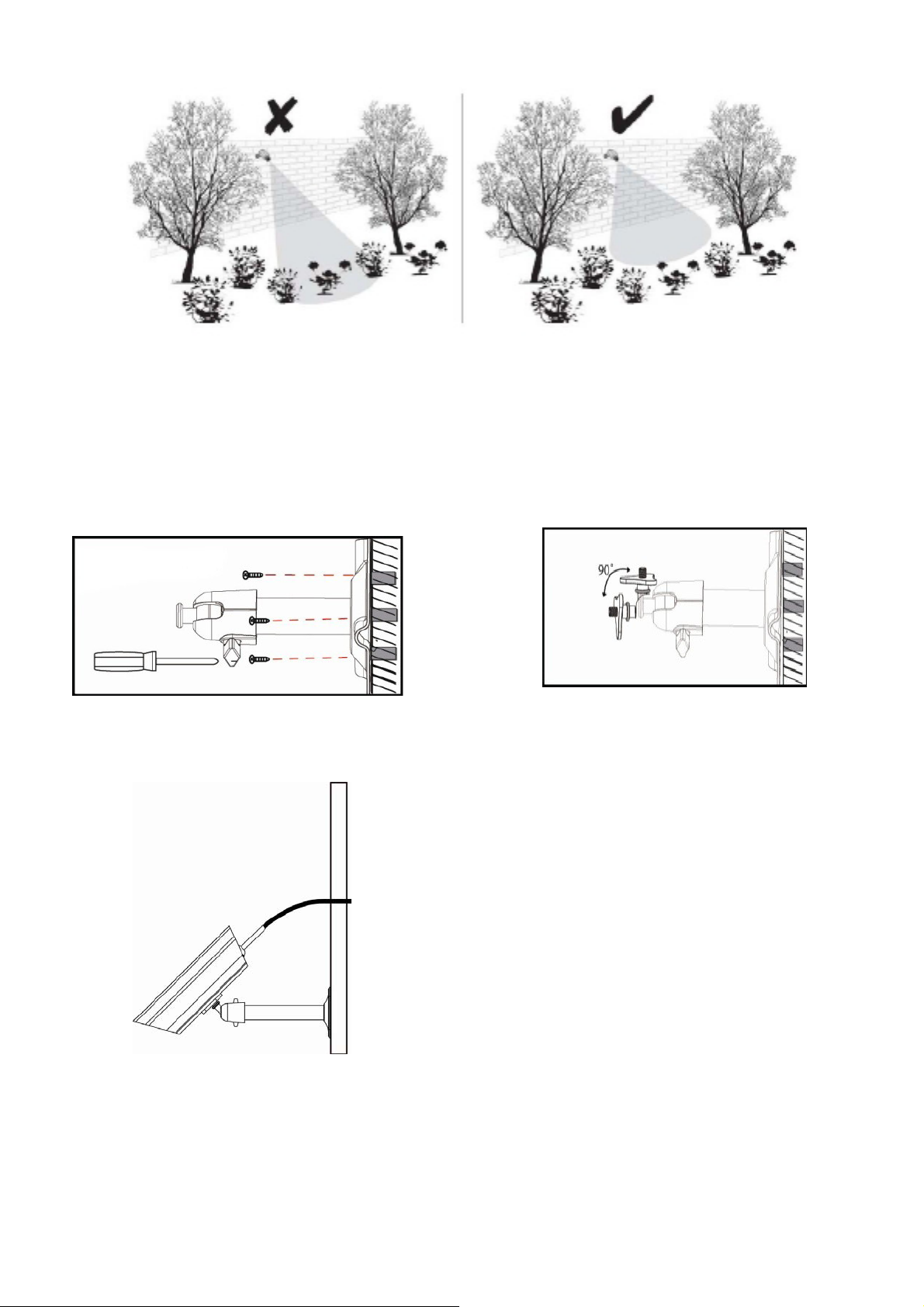
REMARQUE: La Caméra dispose d'une plage de fonctionnement RF en champ ouvert
jusqu'à 500 '.
Installation de la caméra
Desserrer la vis à tête
Sécuriser le Support de la caméra sur une surface stable
Réglez bon angle de vue puis fixez le
joint avec la vis à oreilles.
Page 84

Installation de l’Antenne
Antenne 3dBi
Antenne 5dBi
Réglage du canal de l'appareil photo (facultatif)
La caméra sans fil est fournie préréglée sur le canal 1.
Le moniteur prend en charge jusqu'à 4 caméras. Suivez les étapes ci-dessous dans la
section Configuration de la caméra pour créer ou modifier le canal de moniteur de la
caméra. Si vous ajoutez un autre appareil pour relier le moniteur fourni dans ce kit, alors
assurez-vous que son canal soit réglé sur un canal différent de celui de la (des) caméra (s)
existante (s).
Jumelage de l'appareil photo à un Récepteur (facultatif)
Suivez les étapes de la section de configuration de la caméra pour créer ou modifier le
canal de la caméra. Si vous ajoutez un autre appareil pour relier le moniteur fourni dans ce
kit, alors assurez-vous que son canal soit réglé sur un canal différent de celui de la (des)
caméra (s) existante (s).
Page 85

Branchez l'adaptateur AC / DC
t
Clé d’appariemen
à la prise la plus proche
Remarque:
Si la caméra est située à l'intérieur à 3- 5 pieds à partir de l'écran et le volume de l'appareil
sur le récepteur est allumé, vous pouvez entendre un sifflement sur le moniteur qui est le
retour de l'information captée par le microphone. Dans ce cas, s'il vous plaît déplacez
l'appareil et mettez-le plus loin de l'écran pour éviter ce bruit.
Si la connexion d'alimentation à l'appareil photo est tenue à l'extérieur, assurez-vous que
la connexion soit convenablement protégée.
Pour plus de détails sur l'installation du support de la caméra et les fixations, s'il vous plaît
référez-vous à la section Installation de la caméra.
Régler le moniteur
1. Retournez sur le stand, éteignez l'antenne, branchez l'adaptateur AC / DC à la entrée
sur le côté de l'écran.
Alimentation
Pour caméra sans fil
Vers le Moniteur a écran Tactile
Support de rétraction
Antenne
Entrée SD
Connexion
Alimentation AC
Page 86

2. Appuyez et mainte nez enfoncé le bouton POWER sur le haut de l'écran pour 5 - 6
secondes pour le mettre sous tension.
3. Le récepteur affiche l'écran de bienvenue pendant quelques secondes, puis fait une
transition à la vue en direct.
4. La Carte SD doit être insérée dans l’entrée de carte SD située sur le côté de l'écran.
Remarque: L'écran reste noir ju squ'à ce que l'appareil soit sous tension.
Le moniteur est équipé d'une batterie rechargeable et peut fonctionner jusqu'à 2 heures sur
batterie une fois entièrement chargée (Avec Fonction économie d'énergie activée). Le
moniteur peut être porté à la main n'importe où dans le champ de f onctionnement de la
(des) caméra (s), mais doit être utilisé dans un environnement sec puisqu’il n’est pas
étanche.
Fonctionnement du système
S'il vous plaît referez- vous à la section Fonctionnement du système pour les paramètr es
de l'appareil photo, du système et les paramètres d'enregistrement.
Accès à distance
Peut être fait via iPhone / iPad / iPod Touch w avec iOS 5.0.1 ou supérieur, Smartphone
Android / comprimé v2.3X ou plus connectés à Internet 3G/WiFi.
Pour un Appareil Android
S'il vous plaît reporte z-vous à la section Téléchargement APP Android.
Pour iPhone, iPad1, iPad2, nouvel iPad
S'il vous plaît reporte z-vous à la section Téléchargement APP iPhone.
Remarque:
Le moniteur doit être placé sur la station d'accueil pour permettre la visualisation à
distance.
Si retirée de son support alors la (les) caméra (s) ne peut (peuvent) être consultée (s) que
sur le moniteur.
Page 87

APPRENDRE À CONNAÎTRE LE MONITOR
Réinitialiser
Marche/arrêt
Entrée SD
Alimentation AC
Caméra
Récepteur
(arrière/côté)
Etat de l'Alimentation
Stand de
rétraction
Vue de face
Antenne
Récepteur
alimentation Doc
Vue arrière
Berceau
(arrière/côté)
Connexion de
câble de données
AC prise
d'alimentation
électrique
Connecteur d'antenne
État de la liaison
Capteur de lumière
Micro
SIGNIFICATION DES VOYANTS LUMINEUX
Lumière État Ce que cela signifie
On (Rouge) La caméra est allumée.
Statut d’Alimentation
Statut de Lien
Off La caméra est éteinte.
Clignotant La caméra est en mode d'appairage.
On (Vert) La caméra est connectée au récepteur.
Off La caméra est en veille.
Queue de cochon
d’alimentation
Bouton
d'alimentation/pairage
Page 88

INTRODUCTION AU SYSTEME
Le logiciel du système de votre moniteur fonctionne à travers une série d'écr a ns qui vous
permettent de choisir des groupes d'exploitation. Par exemple, lorsque vous appuyez sur
l’icône de caméra dans le menu pop-up, vous pouvez définir comment vous voulez que le
principal écran de visualisation, « l'écran Live » affiche des images à partir des caméras
connectées. Vous pouvez numériser entre les caméras, toutes les caméras sur un seul
écran (Quad vue), ou seule ment afficher une caméra spécifique.
L'affichage en direct vous permet de visualiser les transmissions de la caméra. Il vous
permet également configurer votre écran et de faire des ajustements. Les Icônes de l’écran
lui-même vous permettent de contrôler la puissance et l'état de l'appareil.
Statut Carte
SD
Menus Pop-ups
Statut
Batterie
Statut conn exion internet
Statut
Enregistrement
Indicateur de Mouvement
Fenêtre de Menus
Pop-ups
Numéro de caméra /
Intensité du Signal
Page 89

ICON QU'EST-CE QUE L’ICONE SIGNIFIE
Sélectionnez comment vous souhaitez que l'écran en direct affiche des
entrées de la caméra:
Mode caméra
Numérisation entre les caméras (5 secondes)
Vue Quad (tout affichage des caméras connectées)
Pleine vue (1 caméra s'affiche en plein écran)
Volume
Paramètres système
Capacité SD Indique la capacité de mémoire restante.
Capacité de la
batterie
Numéro de caméra
Statut de
l'enregistrement
Connexion à Internet Connexion de votre système à l'internet.
Ajustez le niveau de volume.
Accédez au fonctionnement du logiciel du système et la page de
configuration ou affichez les événements enregistrés.
Affiche la capacité de la batterie. Ce graphique montre une batterie
presque plein.
Affiche le numéro de la caméra et la force du signal par l'intermédiaire
des lignes d'état à la gauche du nombre.
Touchez pour lancer ou arrêter l'enregistrement de la caméra
• Fixe - Pas d'enregistrement • Clignotant - Enregistrement
Connecté à Internet Connecte votre système à Internet.
Intranet Connecté Connecte votre système à l'intranet.
Vue a Distance Indique quand la visualisation à distance est en cours.
Mouvement
Prévu Système indique l'enregistrement programmé en cours.
Fenetre Menu Pop
Up
Indicateur Pas de
carte SD
Système indique quand l'enregistrement de détection de mouvement est
en cours.
Ouvrir et fermer l'écran de menu pop-up.
S'affiche en rouge lorsque la carte SD n'est pas présente ou est
endommageé.
Zoom Zoom avant / arrière d'une section particulière de la vidéo en direct
Page 90

Affichage en Direct sur écran
L'écran affiche en direct dans 2 vues – Vue Quad ou Vue Pleine. Vue Quad affiche les
images en 4 quadrants (Uniquement l’appareil d'affichage qui est sur ON). Appuyez sur
un quadrant en affichage pour avoir une vue agrandie de la caméra. Appuyez sur cette
image pour revenir à la Vue Quad.
Fonction zoom
Pour zoomer sur une région particulière,
1. Aller à la vue pleine, puis appuyez sur pour activer le mode zoom.
2. Sélectionnez la zone en appuyant sur la superficie de la zone à agrandir sur l'écran.
Enregistrement vidéo en direct
1. Sur l'écran en direct, appuyez sur pour que la caméra commence
l'enregistrement.
2. Appuyez à nouveau pour arrêter l'enregistrement.
Vous pouvez enregistrer toutes les caméras en même temps. Avec l'enregistrement manuel,
chaque session d'enregistrement (clip vidéo par la caméra) est de deux minutes.
Page 91

Lecture d'une vidéo
Dans le menu pop-up, cliquez sur les icônes
suivantes
L'écran de liste des enregistrements
affiche:
1. Appuyez sur le jour surligné contenant l'enregistrement que vous souhaitez afficher.
L'écran de liste des enregistrements affiche les enregistrements répertori és de ce jour
dans un dossier.
Si vous tapez sur un jour qui n'est pas en surbrillance, un dossier s’affiche sans
enregistrements répertoriés.
2. Appuyez sur l'enregistrement que vous souhaitez afficher. Il s’affiche sur l'écran.
3. Appuyez sur n'importe quelle zone de l'écran qui ne dispose pas d’icônes de
commande pour afficher la barre de progression de la lecture. Appuyez de nouveau
sur cette zone pour la fermer.
4. Pendant que le progrès de la lecture est visible, vous pouvez Avancer / Retourner
rapidement en faisant glisser la barre de lecture.
5. Lorsque la lecture est terminée, appuyez sur
enregistrements.
ou pour revenir à la list e des
Page 92

MENU DU SYSTEME
Dans le menu pop-up, cliquez sur les icônes
suivantes
Les principaux affichages à l'écran:
Le menu du système met en évidence l'option de configuration de la caméra comme le
défaut.
Page 93

p
Écran principal
j
N
Écrans secondaires Ce qu'il fait
Configuration
Camera
Configuration de
l'enregistreur
Configuration du r
seau
é
Configuration de
l'alarme
Configuration Camera Paires de nouvelles cam
éras au récepteur.
Caméra On Rend les caméras visibles à l'écran.
Éclat Éclaircit ou assombrit la vidéo de cette
caméra.
Détection de
mouvement
Documente quand quelque chose se déplace
devant la caméra. Continue d'enregistrer
endant 2 minutes.
Planifier un
Enregistrement
Met en place un calendrier pour
l'enregistrement prédéterminé, durée et
longueurs.
Configuration Internet
Sélectionne le type de connexion Internet à
être utilisé.
Code de sécurité Définit u
n code de sécurité pour l'accès
distant.
Information Réseau Affiche des informations sur votre réseau et le
récepteur du numéro unique de DID.
Période Définit une durée pour l'alarme.
Melodie Sélectionne une mélodie à jouer pour l'alarme.
Configuration du
ème
syst
Conseils Rapides
Économie d'énergie Désactive temporairement l'écran LCD après
que le système ait 2 minutes d'inactivité pour
économiser l'énergie.
Verrouillage
automatique de l'écran
Verrouille l'écran de toute nouvelle activité
usqu'
à ce que le l'écran soit déverrouillé.
Heure Règle l'heure en incréments de 12 heures.
Format de stockage Formatte / efface tout
es les données sur la
carte SD.
Modernisation du
Met à niveau le firmware du r cepteur.
é
système
Par défaut Dresse la liste des valeurs par défaut du
système d'origine.
/ A
Fournit une liste de 10 questions courantes.
Page 94

FONCTIONNEMENT DU SYSTÈME
Écran de configuration de la caméra
Appuyez sur la configuration de la caméra.
Cet écran devrait afficher:
Jumelage de la caméra
Votre appareil est couplé à l'écran à l'usine pour le canal 1.
Pour ajouter une nouvelle caméra à votre système, vous devez le relier à l'autre chaîne.
Dans le menu pop-up, cliquez sur les icônes
suivantes
Les principaux affichages à l'écran:
1. Appuyez sur l'image de la caméra que vous voulez associer. Une icône de traite me nt
s’affiche pour un compte à rebours de 60 secondes.
2. Appuyez et relâchez le bouton de couplage sur le cordon d'alimentation de la caméra
(S'il vous plaît référez-vous à l a section Apprendre
caméra). Le système indiquera que le couplage est réussi lorsque l’appairage est
terminé.
3. Le système ajuste automatiquement la caméra Sur l’écran.
à
connaître le moniteur et la
Page 95

Activation de la Caméra
Lorsque vous ajoutez une caméra à votre système, le système la met en marche
automatiquement.
Dans le menu pop-up, cliquez sur les icônes
suivantes
L'écran affiche:
Un X indique un appareil photo qui est éteint, une vérification indique ON. Tapez sur la
caméra pour la mettre ON ou OFF.
Luminosité
Dans le menu pop-up, cliquez sur les icônes
suivantes
L'écran affiche:
Tapez sur la caméra pour modifier le niveau de luminosité. La luminosité par défa ut est 0,
et la gamme est de -2 à 2.
Page 96

Écran de configuration de l’Enregistreur
Détection de mouvement
Dans le menu pop-up, cliquez sur les icônes
suivantes
L'écran affiche:
Appuyez sur les caméras pour régler la sensibilité sur Off, Faible ou Fort.
Par défaut = faible. L'écran revient à l'écran de détection de mouvement après 10 secondes
ou lorsque vous appuyez sur l'icône Retour.
Alerte Email
Le système peut vous avertir quand il détecte un mouvement à partir de n'importe quelle
caméra en vous envoyant un Alerte email. L'alerte e-mail contient des informations telles
que l'heure à laquelle le mouvement a été détecté et la caméra par laquelle il a été détecté.
Pour activer la fonction Alerte e-mail, vous devez entrer à la fois les adresses e-mails
d’entrée et de sort ie de courriels.
Nous vous recommandons fortement d'utiliser Gmail pour mettre en place le serveur de
courrier sortant.
Le serveur de courrier sortant (serveur SMTP) est responsable de l'envoi de la notification
par courrier électroni que pour i nfo r mer les utilisateurs lorsque le système détecte un
Page 97

mouvement à partir de n'importe quel caméra (La détection de mouvement doit être
activée).
Le serveur de courrier entrant (Email To) reçoit la notification par courrier électronique
envoyée à partir du serveur SMTP, l’utilisateur doit êtr e en mesure de recevoir des
courriels sur un PC sous Windows ou sur des appareils mobiles (comme un iPhone, iPad
ou un Smartphone Android ou tablette) pour recevoir des alertes e-mails du système.
Lorsque vous recevez une alerte par e-mail, vous pouvez visualiser la vidéo en direct de
l'iPhone, iPad, Smartphone Android ou tablette Android à t ravers des applications. Les
Applications gratuites sont disponibles sur l'iTunes App Store ou l'Android Market.
Dans le menu pop-up, cliquez sur les icônes
ci-dessous tels qu'ils apparaissent sur les é
crans:
L'écran affiche:
1. Appuyez sur Activer pour activer une alerte par courriel ou désactiver pour la
désactiver.
2. Appuyez sur le champ du serveur SMTP. Un écran du clavier s’affiche.
3. Entrez votre serveur de messagerie SMTP sortant (exemple: johndoe@gmail.com).
Vous pouvez changer le clavier des caractères alphabétiques vers des chiffres /
symboles et vice-versa en appuyant sur le champ à la gauche de la barre
Page 98

d'espacement. Appuye z sur Entrée. L'écran Alerte Email s'affiche à nouveau.
4. Répétez l'étape précédente pour le champ Mot de passe. Appuyez sur Entrée. Le mot
de passe entré ici doit être le même mot de passe que le mot de passe du compt e de
messagerie sortant.
5. Répétez l'étape 3 pour le champ du courriel. Un seul compte de messagerie entrante
sera accepté par le système. Le compte de messagerie entrant peut être différent du
compte de courrier sortant.
6. Appuyez sur OK pour enregistrer les paramètres, puis appuyez
écran précédent.
Si vous utilisez Gmail comme serveur SMTP sortant, cochez la case SSL et utilisez
les données dans le tableau suivant:
Pour Gmail
Serveur SMTP Smtp.gmail.com Saisissez ceci.
Port SMTP 465 Saisissez ceci.
Nom d'utilisateur XXXX@gmail.com Entrez votre adresse gmail dans
son intégralité, incl ua nt
@gmail.com.
Mot de passe XXXXXXXXXX Entrez le mot de passe pour ce
compte gmail.
Envoyer à XXXX@gmail.com Entrez l'adresse email à laquelle
vous voulez que les alertes soient
envoyées.
pour revenir à l'
Planifier un Enregistrement
Jusqu'à 5 sessions d'enregistrement programmées sont disponibles en une seule journée.
Votre temps d'enregistrement total est limité à la taille de la carte SD. Ces sessions
d'enregistrement doivent commencer et finir dans une seule période de 24 heures. Elles ne
peuvent pas traverser le jour su ivant.
Dans le menu pop-up, cliquez sur les icônes
suivantes
L’écran de planifi cation
d’enregistrement s’affiche:
Page 99

1. Tapez le numéro de la caméra / canal que vous souhaitez enregistrer (1 - 4).
Plusieurs caméras peuvent être sélectionnées.
2. Réglez le début de l'enregistrement et l'heure de fin. Appuyez sur l'heure et les boîtes
de minutes séparément et utilisez les touches des flèches HAUT et BAS pour les
faire défiler les temps.
3. Appuyez sur le bloc AM / PM pour basculer entr e eux.
4. Tapez sur le champ de date vide. L'écran Calendrier de l'enregistrement annexe
s'affiche.
5. Tapez sur la date à laquelle vous souhaitez commencer l'enregistrement. L'écran
precedent s’affiche.
6. Mettre en place l'enregistrement, puis appuyez sur Enregistrer. Vous pouvez
sélectionner une autre session d'enregist rement sur le calendrier.
Effacer un enregistrement programmé
1. Accédez à l'écran du calendrier d'enregistrement.
2. Tapez sur l'enregistrement programmé que vous souhaitez effacer (1-5). L'écran
affiche les paramètres de cette programmation .
3. Appuyez sur CLEAR. L'écran est remis à la valeur par défaut pour cette fente
d'enregistrement.
Écran de configuration du réseau
L'écran de configuration du réseau vous permet de sélectionner votre type d’internet,
établir un code de sécurité. Vous pouvez également afficher la configuration du système
par défaut.
Dans le menu pop-up, cliquez sur les icônes
suivantes
L'écran de configuration réseau
s’affiche:
Page 100

Configuration Internet
1. Appuyez sur l'icône d'installation d'Internet pour afficher l'écran de configuration
Internet.
2. Tapez sur votre sélection et remplissez les champs demandés. Appuyez sur OK.
Sélection Champs
IP statique
DHCP Aucun
3. Appuyez sur OK à l'invite de redémarrage du système. L'écran de configuration du
réseau s'affiche.
- Adresse IP
- Masque de sous-réseau
- Passerelle par défaut
- Serveur DNS
 Loading...