

Page 1
AWM900S
High Power AM/FM/CD Player
Owner ’s Manual
Designed Specifically for the
Van and RV lndustries
Page 2

Thank you for your purchase of the AWM900S. It is designed to give you good value and many
hours of listening enjoyment. Please read this manual carefully, as it should be able to answer
many of your questions about the operation and features of this product.
IMPORTANT NOTES
Avoid installing unit in locations described below:
-Places exposed to heat radiating appliances such as electric heaters
-On top of other stereo equipment that radiates too much heat
-Places lacking ventilation or dusty places
-Humid or moist places
Features:
-AM/FM Wallmount Stereo with CD Player
-Digital Display Type Tuner
-Locking Power/Speaker Connector
-Clock/Alarm
-2-Channel (Left, Right with A/B Speaker Outputs)
-Auxiliary input Function
-Backlit Controls
-Reverse Polarity Protection
-50 Watts Power Output
-12VDC
-Bass/Treble
-Preset EQ (Rock, Pop, Classis)
-Alarm Defeat Switch
REAR PANEL FEATURES
-External Fuse Holder
-Main Wiring Pigtail with Locking Amp Connector (12-Pin)
-Auxiliary Input Phone Jacks (Left and Right)
Manual contents: Page:
Features-Manual contents 2
Controls Identification 3
Operation Instructions 4-5
Hook Up Wiring Color Code 5
Installation 6
Specifications 6
Warranty Statement 7
Page 2
Page 3
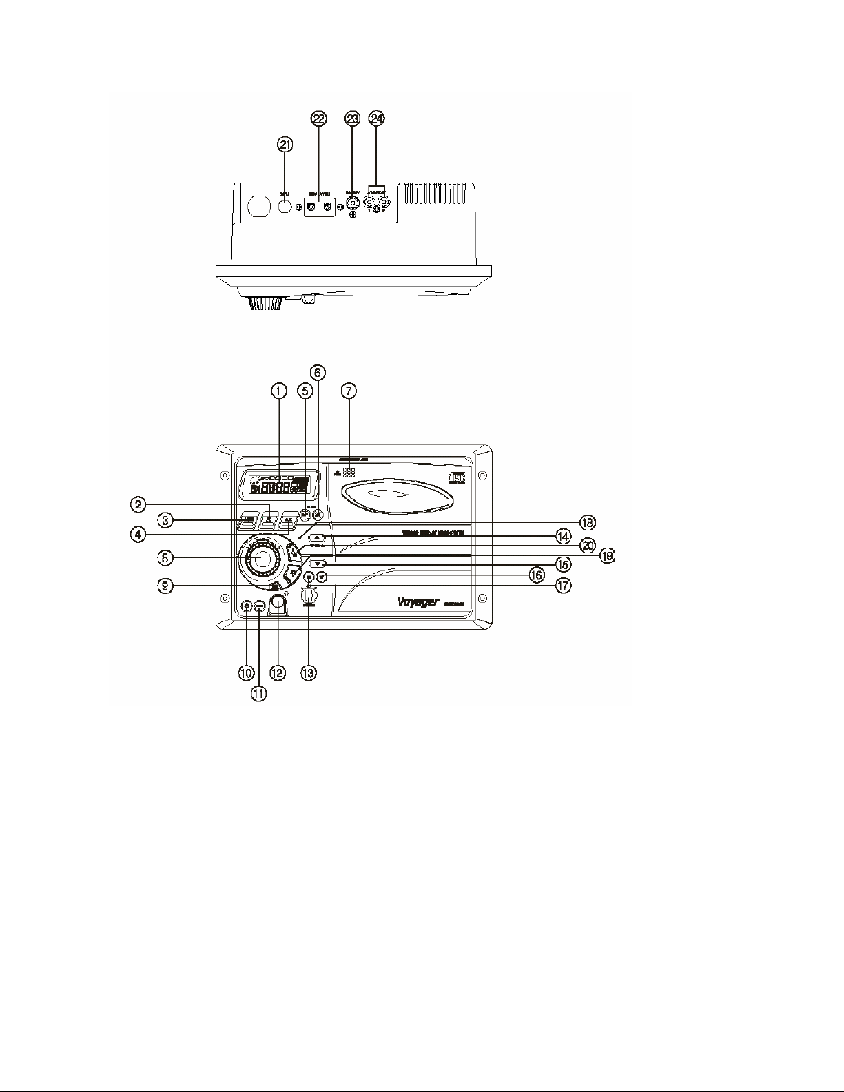
Controls Identification:
Controls Identification
1) Display Window
2) CD P lay/Pause Button
3) Band(AM/FM) Button
4) AUX Selector Button
5) Alarm Set Button
6) Alarm On/Off Buttons
7) CD E ject Button
8) Radio Tuning Control
9) Audio Adjust Selector Button (Volume,
Bass, Treble, Balance)
10) Power Switch
11) Mute Button
12) Stereo Headphone Jack
13) Speaker Selector
14) Volume Up Control Button
15) Volume Down Control Button
16) Time/Frequency Selector Button
17) Preset EQ Button (Rock, Pop,
Classic)
18) Reset Button
19) Track Up / Minute Set Button
20) Track Down /Hour Set Button
21) Fuse
22) FM Antenna T erminals
23) Car Antenna Jack- 75 Ohm
24) RCA Auxiliary Input Jacks
Page 3
Page 4

Operating Instructions:
NOTE: Number in parenthesis (#) corresponds with “Control Identification” on page 3.
LIQUID CRYSTAL DISPLAY PANEL
The liquid crystal display (LCD) panel displays the frequency, time and activated functions.
Note: It is characteristic of LCD panels that, if subjected to cold temperatures for an extended
period of time, they will take longer to illuminate than under normal conditions. In addition, the
visibility of the numbers on the LCD may slightly decrease. The LCD readout will return to normal
when the temperature increases to a normal range.
TUNER
1) Turn power on by pushing the Power switch(10).
2) Use the Band Selector(3) to select either AM or FM
3) Use the Speaker Selector Switch(13) to choose speaker output
4) Use the Tuner Control(8) to select station
5) Adjust Volume Control(14 or 15) to suit taste
CD PLAYER
1) Use the Speaker Selector switch (13) to choose between speaker output, headphones or both.
2) Press the CD eject button (7) to eject any CD’s that may already be in the player.
3) Press the CD Play/Pause button (the same as the CD Source Select button).
4) You may change tracks by using the Track Up or Track down buttons (19 or20).
5) To change to AM/FM or Aux. Inputs, press the corresponding button; to return to CD press the
CD button.
6) To eject the CD, press the CD eject button(7).
7) CD Disc Insert Method
Door Open Disc Insert Door Close
Page 4
Page 5

AUXILIARY INPUT
1) Push Power Switch (10) “On”.
2) Using the source Selectors (4), choose the button labeled “AUX”.
3) If there is an external source (example: CD shuttle) connected to the Auxiliary Input Jacks (24)
on the rear of the radio, then you can listen to your external source through the system.
SETTING THE CLOCK
1) Push Power Switch (10) “On”.
2) Press the T/F button to display the clock
3) Hold the T/F button (16) and simultaneously use the H and M buttons
(19 and 20) to adjust hours and minutes.
Note: The T/F also toggles between time and radio frequency on the display.
USING THE AUDIO ADJUST BUTTON
1) You can toggle between volume, treble, bass and balance control by pressing the Audio Adjust
button (9)
2) Once at the desired function, you can use the volume buttons to adjust.
SETTING THE ALARM
1) Hold the Alarm set button (5)
2) Use the H and M buttons (19 and 20) to adjust hours and minutes.
3) The alarm On/Off button (6) activates or deactivates the alarm.
BEEP FEATURE
1) Hold the Audio Adjust button to enable the beep feature (9). Lower right side of the display will
display an audio symbol when this feature is turned on.
2) When this feature is on, turning different features on or off will produce two different tones,
higher tone for ON and lower tone for OFF.
3) Completely removing power from the unit will turn the beep feature off.
Page 5
Page 6

Wiring Color Code:
WIRING COLOR CODE
FOR AWM-900S
COLOR FUNCTION
ORANGE/WHITE STRIPE +12VDC IGNITION POWER
GREEN/WHITE STRIPE +12VDC BATTERY POWER
BLACK/WHITE STRIPE POWER GROUND (-12VDC)
WHITE LEFT (A) SPEAKER (+)
VIOLET LEFT (A) SPEAKER (-)
BLUE RIGHT (A) SPEAKER (+)
LIGHT GREEN RIGHT (A) SPEAKER (-)
RED LEFT (B) SPEAKER (+)
VIOLET/BLACK STRIPE LEFT (B) SPEAKER (-)
YELLOW RIGHT (B) SPEAKER (+)
LT GREEN/BLACK STRIPE RIGHT (B) SPEAKER (-)
Page 6
Page 7

Installation:
1) Cut a mounting hole in the desired location using mounting hole diagram (below) and use the
four 3x20min self tapping screws provided to mount the unit.
2) Route power, speaker and antenna cables through hole and connect to unit as outlined in the
Wiring Color Code diagram on the previous page.
3) After making sure connections are correct, test operation.
Specifications:
Operating Voltage: 11-16VDC
Output Power: 50 Watts Total (25 Watts per Channel)
Output Wiring: 2/4 speaker and Headphone System
Output Impedance: Compatible with 4-8 Ohm Speakers,
4 Ohm Load Min.
Tuning Range: (AM)530-1720 KHz
(FM) 87.5-108 MHz
Sensitivity (AM) less than 15uv
(FM) less than 2.5uv
FM Stereo Separation: More than 30dB
CD Frequency Response: 20-20,000 Hz
CD Channel Separation: 50dB
CD S/N Ratio: 60dB
CD Distortion: 0.3%
SizeOverall Size: 10.43”(W)x7” (H)x6.26 (D)
265mm(W)x178mm(H)x159mm(D)
Mounting Size: 9.25”(W)x6.05”(H)x5.25”(D)
235mm(W)x154mm(H)x133mm(D)
Weight: 4 lbs.(1.8 Kg)
Page 7
Page 8

WARRANTY
90 DAY / 12 MONTH LIMITED WARRANTY
AUDIOVOX SPECIALIZED APPLICATIONS, LLC (the Company) warrants to the original retail
purchaser of this product that should this product or any part thereof, under normal use and
conditions, be proven defective in material or workmanship within 90 days from the date of original
purchase, such defect(s) will be repaired or replaced (at the Company’s option) without charge for
parts and repair labor. After the initial 90 day period and for a period of 12 months from the date
of the original purchase, the Company will supply at no charge a replacement for any defective
part(s).
To obtain repair or replacement within the terms of this warranty, the end user should contact the
O.E.M. The product is to be delivered to the OEM or original place of purchase, with proof of
warranty coverage (e.g. dated bill of sale, and serial number of the unit, and vin#), specification of
defect(s), transportation prepaid, to an approved warranty station.
This warranty does not extend to the elimination of externally generated static or noise, to the
correction of antenna problems, to costs incurred for removal or reinstallation of the product, or to
damage to any tapes, cd’s, dvd’s, speakers, accessories, or electrical systems.
This warranty does not apply to any product or part thereof which, in the opinion of the Company,
has been damaged through alteration, improper installation, mishandling, misuse, neglect, or
accident. THE EXTENT OF THE COMPANY’S LIABILITY UNDER THIS WARRANTY IS
LIMITED TO THE REPAIR OR REPLACEMENT PROVIDED ABOVE, AND, IN NO EVENT, SHALL
THE COMPANY’S LIABILITY EXCEED THE PURCHASE PRICE PAID BY THE PURCHASER
FOR THE PRODUCT.
This warranty is in lieu of all other express warranties or liabilities. ANY IMPLIED WARRANTIES,
INCLUDING ANY IMPLIED WARRANTY OF MERCHANTABILITY, SHALL BE LIMITED TO THE
DURATION OF THIS WARRANTY. ANY ACTION FOR BREECH OF ANY WARRANTY
HEREUNDER INCLUDING ANY IMPLIED WARRANTY OF MERCHANTABILITY MUST BE
BROUGHT WITHIN A PERIOD OF 30 DAYS FROM THE DATE OF ORIGINAL PURCHASE. IN
NO CASE SHALL THE COMPANY BE LIABLE FOR ANY CONSEQUENTIAL OR INCIDENTAL
DAMAGES FOR BREECH OF THIS OR ANY OTHER WARRANTY, EXPRESS OR IMPLIED
WHATSOEVER. No person or representative is authorized to assume for the Company any
liability other that expressed herein in connection with the sale of this product.
Some states do not allow limitations on how long an implied warranty lasts or the exclusion or
limitation of incidental or consequential damages so the above limitations or exclusions may not
apply to you. This warranty gives you specific legal rights and you may also have other rights
which vary from state to state.
Visit us at www.asaelectronics.com
Page 8
 Loading...