

Page 1

AOM40MR
4.0” LCD Mirror / Rear Observation monitor
OWNER’S MANUAL
Revised 2-12-03
Page 2
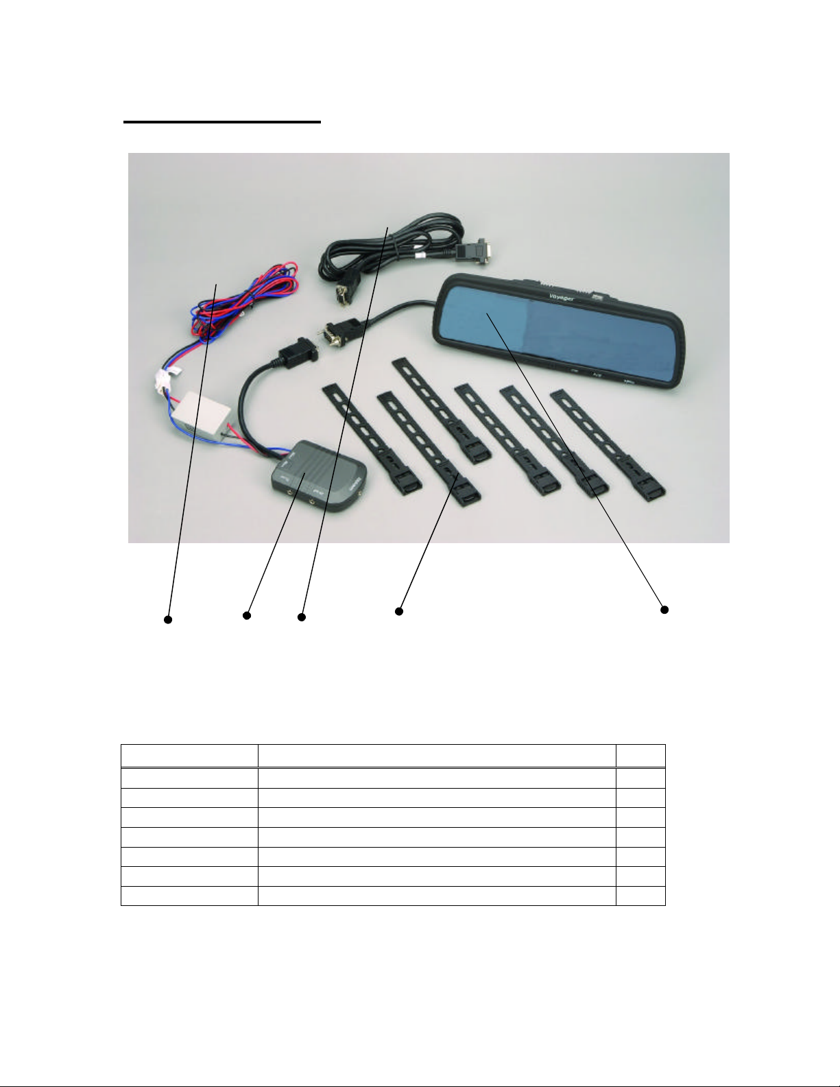
Package Contents:
4 2 3 5 1
Item Description Qty
1 LCD Mirror 1
2 Junction Box 1
3 Interconnect Cable 1
4 Power Harness 1
5 Mounting straps 6
6 Hands-free cable 1
7 Owner’s manual 1
2
Page 3
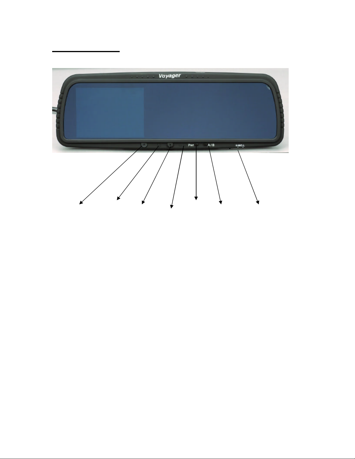
Mirror Controls
MIC Brightness LED Volume PWR A/B Switch Hi – Low
Control MIC adjustment
Figure 1: Rear View Mirror
? MIC – Microphone for use with hands free cell phone feature.
? Brightness control – Adjusts the brightness level of th e LCD viewing area of
the mirror.
? LED – Power indicator indicating that the mirror is turned on.
? Volume – Adjust the volume level for hands free cell phone use and audio
from rear camera. (Camera must have mic/audio to function)
? PWR – Power button turns Observation and hands free function off and on.
? A/B switch – Toggles between Camera A and Camera B.
? H-Mic -L – Hi and Low level setting for microphone sensitivity. Low setting
helps reduce background noise.
3
Page 4

System Connections
HANDSFREE
A2-out
V2-out
in-1
AV
in-2
AV
? AV IN1 – Camera 1 input. (f or Backup camera use) See Notes 1 and 2.
? AV IN 2 –Camera 2 input. See note 2.
? A2 Out – Audio output to second monitor for Camera 2 if camera 2 is used.
(Optional)
? V2 Out - Video output to second monitor for Camera 2 if camera 2 is used.
(Optional)
? Hands Free – Used to connect to a cell phone to allow hands free use.
Connection Notes:
1) AV IN1 is the primary input. If only one camera is used connect the camera to
AV IN 1. If one of the cameras is being used for rear observation function,
connect this camera to AV IN1 only. When the reverse circuit is triggered, AV
IN1 will override AV IN2.
4
Page 5

HANDSFREE
Connection Notes (Continued):
2) Special camera adapter harnesses are required and available for use of this
system with Voyager observation cameras. See Page 6 for more information.
Wiring Diagram
A2-out
V2-out
in-1
AV
in-2
AV
? Intermediate Harness – Optional, can be connected between the Mirror and
the Junction Box if necessary.
? Power Harness – To be connected to vehicle wiring.
1. Empty
2. Black Wire to chassis ground.
3. Red Wire to 12VDC Accessory circuit.
4. Blue wire (Optional) to be connected to vehicles reverse circuit.
5
Page 6

Installation Notes:
Do not connect Blue wire directly to 12VDC battery or Accessory. Doing so will
cause the monitor to be on at all times. The “Pwr” button will not function when
12V is applied to the trigger (blue) wire. Only connect the blue trigger wire to a
source that is switched on (12V) when the vehicle is put into reverse gear (such as
reverse lights).
Optional installation if the system is not being use d for rear/backup observation is
to leave the blue trigger wire disconnected. If this option is chosen, the user must
manually turn the system on by pressing the “Pwr” button.
Camera Adapter Cables (Available Separately)
P/N 31200004 – Allows connection to Voyager CEC-series camera cables
P/N 31200005 – Allows connection to Voyager VEC-series camera cables
6
Page 7

www.asaelectronics.com
7
 Loading...