

Voxx PSB111 User Manual
Par
king
Sensor
Use
r's G
uide
wire *
4
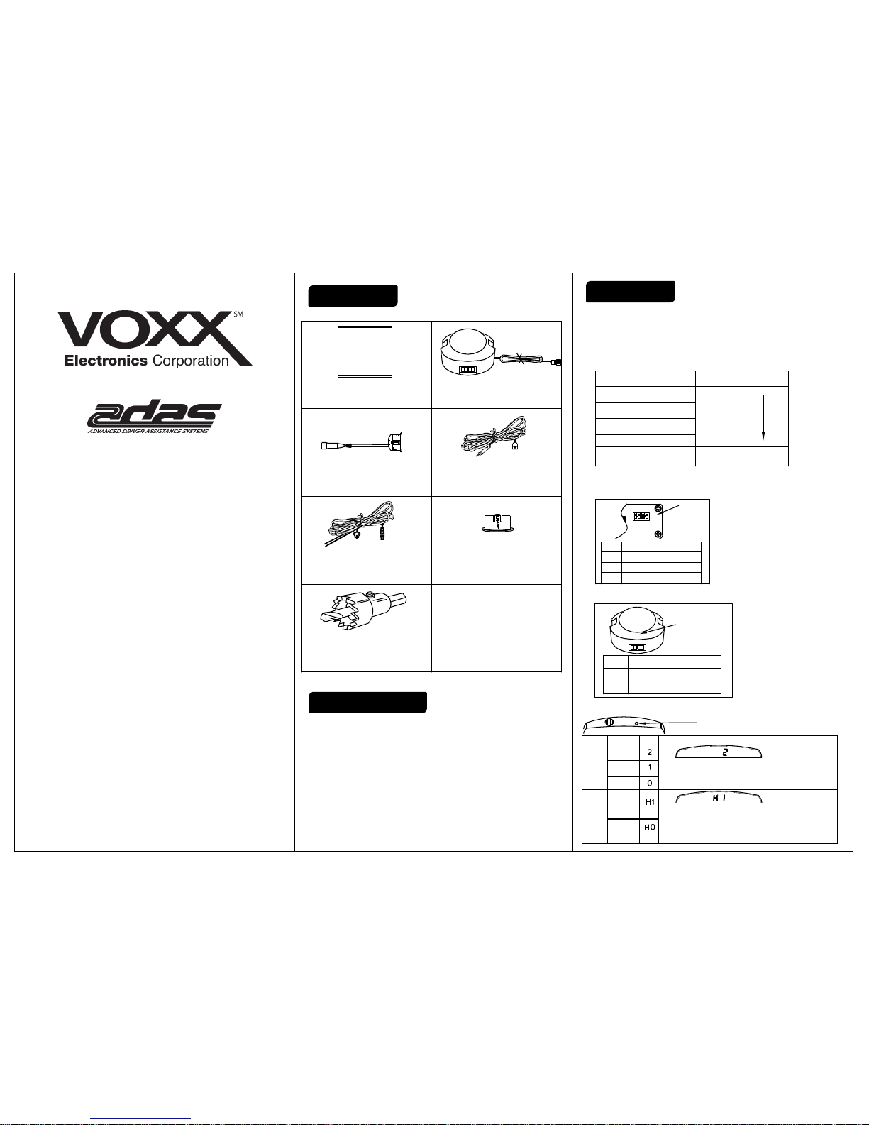
1. Operated Voltage: DC 10~15V
2. Operated Temp.: -30~+70°C
3. Comsumption.: ≤4W
4. Sensor detection distance:
Left and right:2 ft.
Center left and right:5 ft.
1.Working condition:
To engage sensor system, turn ignition key to the ‘ON’
position and move gear selector to reverse gear.
2. Warning mode:
3. Setup fucntion
(A)Control box
(Buzzer
∅ 22mm hole saw* 1
Power wire * 1
Sensor * 4
Control box * 1
0°sensor
masker *
4
sensor branch
Hi Lo Off
Buzzer * 1
Hi Lo Off
Default
4
3
2
1
L
ow sensitivity ON&OFF
Spare
tire learning ON&OFF
N/A
N/A
Off
Lo
Hi
Turned
off
Low volume
Highvolume
<1 ½ ft.
2 ft. ~1 ½ ft.
3 ft. ~ 2 ft.
4 ft. ~ 3 ft.
4 ft. ~ 5 ft.
Obstacle distance
Constant beep
Slow Beep
Medium Beep
Fast Beep
Warning
Faster
ll
Closer
OFF
ON
1 2 3 4
Default
(C)Display (Optional)
Function setting
button
Metric
vs
Imper
ial
Disp
lay
Volume
Mode
The
Imperia
l
system
The metri
c
system
Off
Low
Hig
h
D
efiniti
on
Show
(default)
P
ress and hold the
settings button, then the buzzer alarm once
a
nd show "H1". If you want toadjust thedisplay mode,please
and release
the button and continue pressing the settings button
,
t
he display will cycle
"H0" and "H1". ". Release button when
display shows desired setting
.
(default)
Press the setting button, the buzzer will sound
once and show
"2". If you wantto adjustvolume, continue pressing the settings
button, thedisplay will cycle
"0", "1" and "2". Release button
when display shows desired setting
.
Note
Parts List
Specification
Function
PSB111
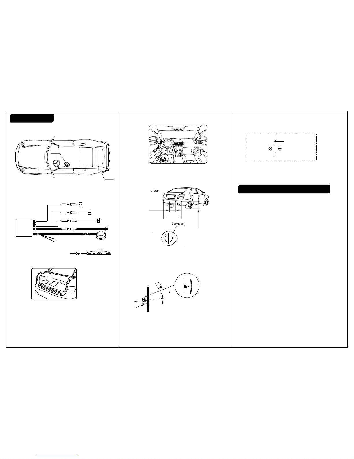
1. Installation position
2. Wiring diagram
4.Buzzer
3. Control box
a. Install the control box in the
left side of the trunk.
b. Please clean the surface before installing
the
control box.
NOTE:
Control box is not weather resistant.
Do not mount outside of vehicle.
a. Install buzzer
under the driver’s
seat.
b. Be sure to route wiring away from any moving
parts
5. Sensor
(A) Installation position
(B) Sensor hole
a. Verify hole saw is the same size as sensor.
b. Please remove the burrs around the hole after drilling,
ensure the size of the hole and make sure there’s no debris
or metal / plastic parts blocking
the sensor. Objects blocking
or covering the sensor will produce false alarms.
(C) Sensor installation
a. Make sure
the sensor
angle is between 0~8°
b. Connect the sensors according to the
labels
c. Please make sure that the wiring harness
is fixedand far away
from exhaust pipe
.
Vertical
+0.2
22mm
-0
Bumper
sensor
bumper
Vertical
6.Connection guide
a. This product is used to 12V vehicle;
b. Connection of reverse light wire (red);
1. If the b
uzzer gives warning
, even if there's no obstacles,
please check t
he sensor
installation direction, and makesure
the sensor surfaceis not angled toward the ground
.
2. If the direction of the warningis not correct, pleasecheck the
connection of the sensor.
3. Clean any debris from sensor surface and surrounding areas.
4. When running on large angle slope, grass or gravel road, it is
possible the system will produce a false warning.
"UP"
faces
upward
Left
sensor
Center
right
sensor
Center left
sensor
Right
sensor
c. Connect GND
Conne
ct the ground ring (black wire) to a metal
part on vehicle body.
1 1/3 ~ 1 2/3 ft.
3 2/3 ft.
~ 4 ¼ ft.
1 ½ ft. ~ 2 ¼ ft.
Buzzer
Hi Lo Off
Hi Lo Off
R
CR
CL
Control
box
L
Sensor
Black cable,GND
Red cable, reverse light
Hi Lo Off
Power wire
Buzzer
Reverse
light
GND
Connect red reverse
light wire here
Control
box
Display (Optional)
Testing & Troubleshooting
Installation
 Loading...