

Voxx ELITE911 Installation Instructions Manual
Vehicle Security System
INS0883
Rev. A
11/98
Installation Instructions
This device complies with part 15 of the FCC rules and with RSS-210 of the
industry Canada. Operation is subject to the follo wing two conditions: (1) this
device ma y not cause harmful interference, and (2) this de vice must accept an y
interference received, including interf erence that may cause undesired oper ation.
Technical Support
For Authorized Dealers - (800) 421-3209
Hours: 8:00 a.m. - 7:00 p.m. EST Monday thru Friday
10:00 a.m. - 2:00 p.m. EST Saturday
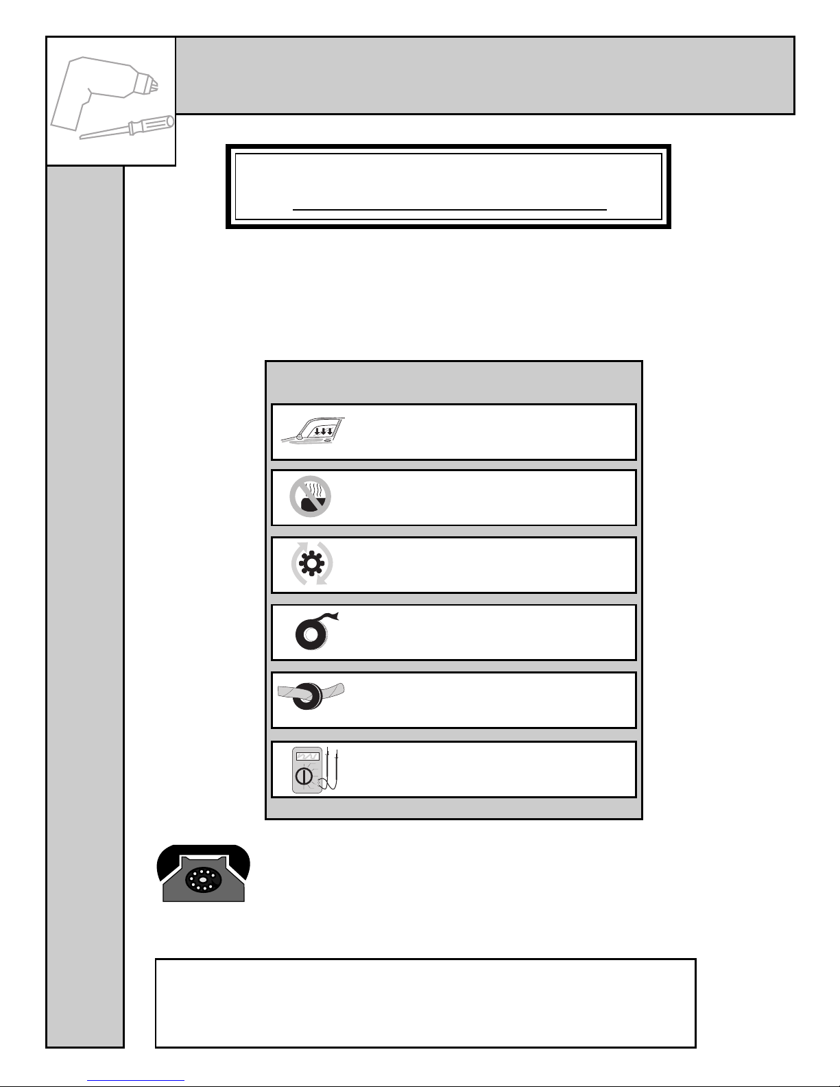
Avoid mounting components or
routing wires near hot surfaces
Avoid mounting components or
routing wires near moving parts
Tape or loom wires under hood for
protection and appearance
Use grommets when routing wires
through metal surfaces
Use a voltmeter for testing and
verifying circuits
PROFESSIONAL INSTALLATION
STRONGLY RECOMMENDED
Installation Precautions:
Roll down window to avoid locking
keys in vehicle during installation
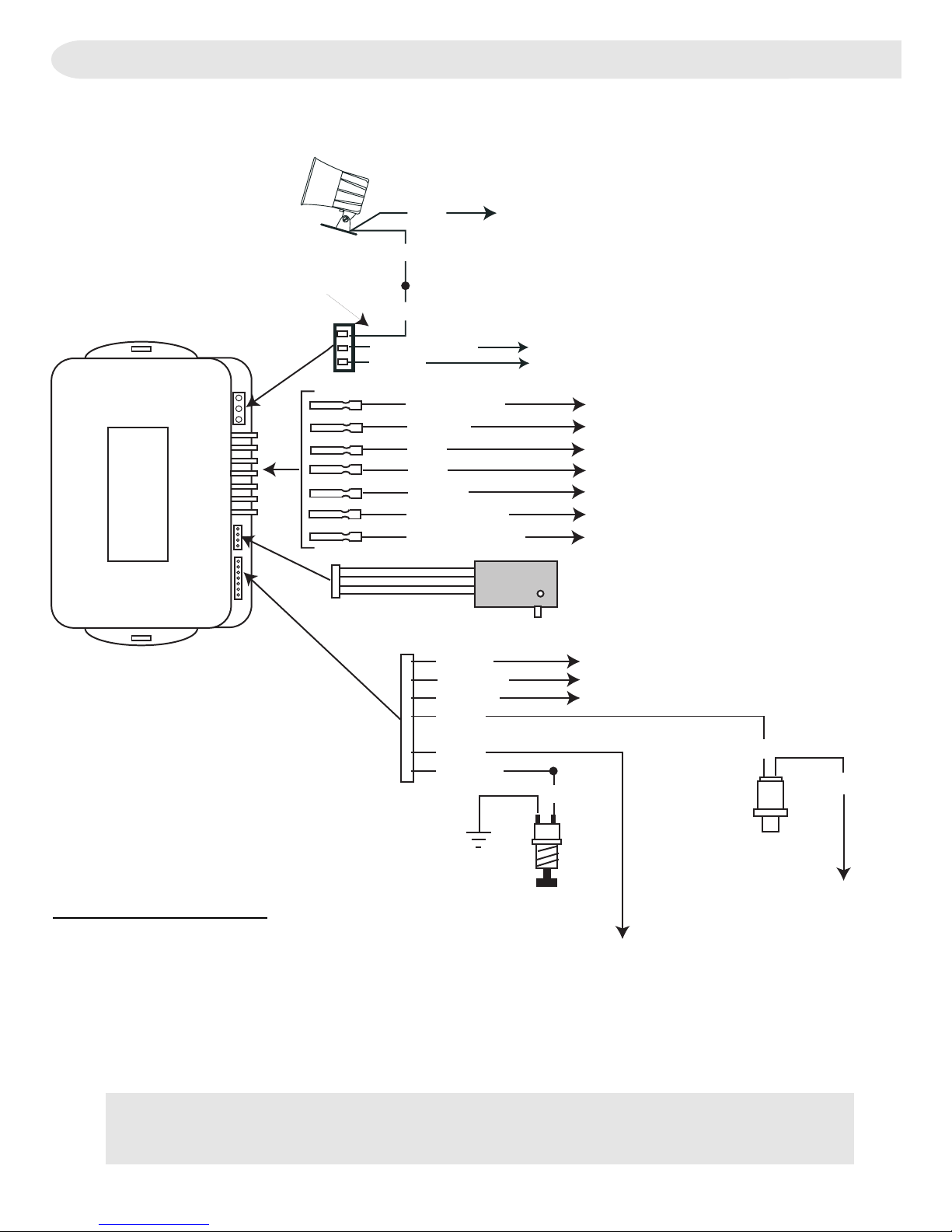
Y10 / Y11
2
ORANGE/BLACK
VIOLET
WHITE RED
WHITE
TAN
RED
BLACK
BLUE/BLACK
GREEN/BLACK
STARTER KEY
STARTER MOTOR
TRUNK RELEASE (-) (Y-11 ONLY)
+12 VOLTS
CHASSIS GROUND
(-) LOCK / (+) UNLOCK
(-) UNLOCK / (+) LOCK
PARKING LIGHT OUTPUT (+)
RED
BLACK
ORANGE
SIREN OR
HORN
OUTPUT (-)
SHOCK SENSOR
WHITE
YELLOW
GREEN
GRAY
BLUE
BROWN
POSITIVE DOOR TRIGGER
NEGATIVE DOOR TRIGGER
NEGATIVE HOOD/TRUNK TRIGGER
DISARM
BUTTON
BROWN
SWITCHED
POWER
BLACK
RED
STATUS
INDICATOR
+12 VOLTS
FUSED +12V SOURCE
ILL. ENTRY / ARMED OUTPUT (-) (Y-11 ONLY)
System Layout
Refer to Wire Color / Location Char t for specific wire color,
location, and polarity information.
Module Identification:
7 Tab Connectors = Y-11
6 Tab Connectors = Y-10
3
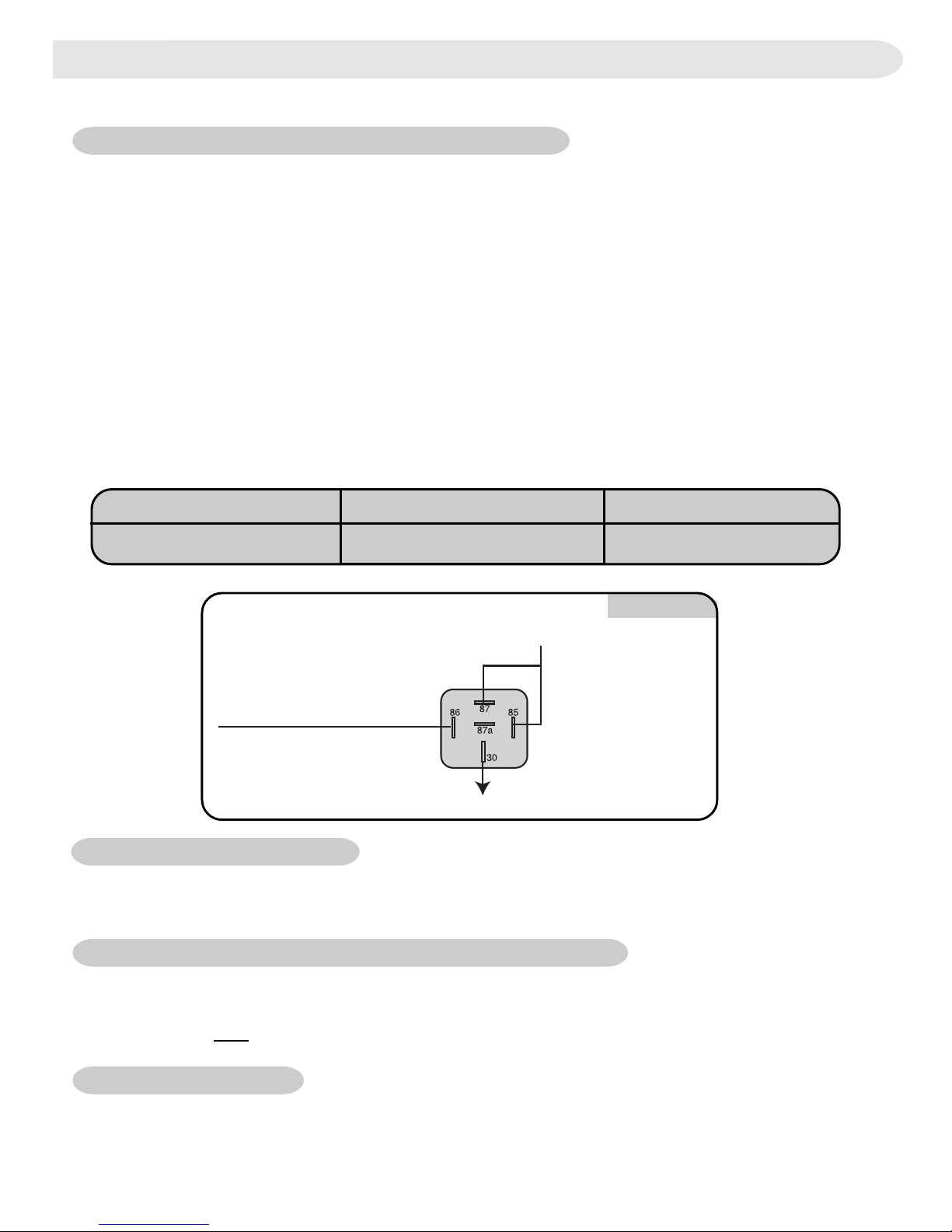
+12V
Horn
Module ORANGE wire
1. Installation
A. Siren / Horn (ORANGE on 3-Pin Connector)
Make appropriate connections below.
Siren
• Mount bell housing downwards.
• Use at least two (2) screws to secure siren to mounting location.
• Connect siren BLACK wire to module ORANGE wire.
• Connect siren RED wire to a fused +12-volt source.
Horn
Circuit verification
-
Negative Systems
- Target wire will register ground when horn is pressed.
Positive Systems
- Target wire registers voltage when horn is pressed.
Diagram 1
Horn
Wire Relay Diagram 1
Connect to target wire.
Positive Negative
Connection
B. 12V+ Main Feed (RED)
• Connect to vehicle battery or to main 12-volt lead at ignition switch harness.
Circuit Verification
- Target wire registers voltage at all times.
C. 12V+ Switched Feed (BLUE on 7-Pin Connector)
• Connect to switched 12-volt lead at ignition switch harness.
Circuit Verification
- Target wire registers voltage when ignition key is tur ned to the
ON position and START position.
D. Ground (BLACK)
• Attach to grounded metal point of vehicle chassis.
Note: When installing multiple components (such as an alarm and remote starter),
ground the units separately.
Fused
4
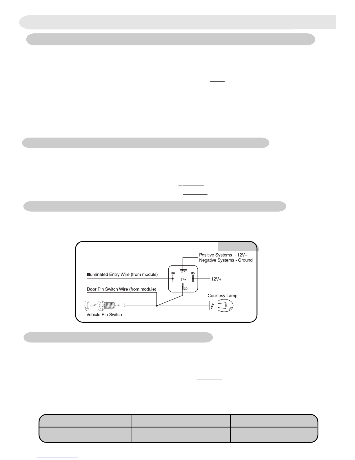
Diagram 2
Door System - Relay Needed
G. Illuminated Entry (VIOLET on 3-Pin Connector) (Y-11 Only)
•
Circuit Verification -
Target wire is usually the door pin switch wire. Refer to
section F for verification guideline.
• Add a relay and connect as shown below:
H. Trunk / Hatch Release (TAN) (Y-11 Only)
•
Circuit V erification
- Refer to Vehicle Wire Color and Location Chart for circuit
type and location, or verify the vehicle wire using the following guideline:
•
Positive Systems
- Target wire registers voltage when the trunk / hatch is
opened using the vehicle button.
•
Negative Systems
- Target wire registers ground when the trunk / hatch is
opened using the vehicle button.
1. Installation
F . Door Pin Switches (YELLO W or WHITE on 7-Pin Connector)
Connect appropriate module wire to vehicle target wire. (See diagram 2 below.)
Circuit V erification
- Refer to Vehicle Wire Color and Location Chart for circuit
type and location, or verify the vehicle wire using the following guideline:
•
Positive Systems
- Target wire registers voltage when any door is opened.
•
Negative Systems
- Target wire registers ground when any door is opened.
E. Starter Interrupt
• WHITE/RED -Starter Key Side
• WHITE - Starter Motor Side
• Connect to vehicle starter wire at ignition switch harness.
Circuit Verification
- Target wire registers voltage only when ignition key is turned
to the START position.
Circuit Verification after starter wire is cut:
• KEY SIDE of starter wire registers voltage when ignition key is turned to
the START position.
• MOTOR SIDE of starter wire registers no voltage.
Trunk Release
Wire Relay Diagram 3
Connect to target wire.
Positive Negative
Connection
 Loading...