

Voxx ASCL6 Installation Manual

COMPLETE INSTALLATION & PROGRAMMING GUIDE
Telematics Communicator System
ASCL6
This system must be installed by a professional.
NOTICE
The manufacturer will accept no responsability for any electrical damage resulng from
improper installaon of this product, be that either damage to the vehicle itself or to the
installed device. This device must be installed by a cered technician. Please review the
Installaon Guide carefully before beginning any work.
EN-20201019-A

TABLE OF CONTENTS
HARDWARE PARTS ................................................................................................................................ 3
iDATASTART HCx ..................................................................................................................................... 4
iDATASTART VWx .................................................................................................................................... 6
iDATASTART BM or BZ .......................................................................................................................... 8
AKX or OEM ............................................................................................................................................. 10
ADS-AL-CA / OL-MDB-ALL ................................................................................................................12
CRIMESTOPPER ......................................................................................................................................14
FLASHLOGIC FL-CAN ........................................................................................................................... 16
FLASHLOGIC FLRS ................................................................................................................................18
FLASHLOGIC FLRSBA ........................................................................................................................ 20
FLASHLOGIC FLCMVW ....................................................................................................................... 22
COMPUSTAR CM7000 / CM7200 / POLARSTART PRS-16 ...................................................24
COMPUSTAR CM6200 .........................................................................................................................26
COMPUSTAR DC2 ..................................................................................................................................28
COMPUSTAR DC3 ................................................................................................................................. 30
POLARSTART PRS-13 ...........................................................................................................................32
DIRECTED DBALL 2 ..............................................................................................................................34
DIRECTED DB3 .......................................................................................................................................36
DIRECTED 4X10 - 5X10 - AF-D600 - ASD200 - ASD-600 ....................................................38
DIRECTED DS4 - DS4+ ....................................................................................................................... 40
FORTIN EVO-ALL ..................................................................................................................................42
FORTIN EVO-ONE ................................................................................................................................ 44
PRESTIGE (E) Models .......................................................................................................................... 46
PRESTIGE (Z) Models .......................................................................................................................... 48
PURSUIT (E) Models ............................................................................................................................ 50
PURSUIT (Z) Models ............................................................................................................................. 52
CODE SYSTEMS ......................................................................................................................................54
OLDER CODE SYSTEMS......................................................................................................................56
OMEGA RS-X70 ......................................................................................................................................58
OMEGA AL-XX70-B ............................................................................................................................. 60
OMEGA OLRS ..........................................................................................................................................62
MIDCITY SMARTKEY STARTER ....................................................................................................... 64
DSE 503AIR 5R-85 ............................................................................................................................... 66
DSE iSTART2 - 3 .....................................................................................................................................68
LED Status Reference Chart ............................................................................................................. 70
RESET PROCEDURE ............................................................................................................................ 70
2
HARDWARE PARTS
CREATE AN ACCOUNT
Before begining the installation and setting the configurations of a CL6 unit, we strongly
recommend downloading the Application from the App store and create a user account.
a. Go to the App store (Apple) or Play store (Android) and Search for “CL6”. Download and install
the Free Application.
b. Launch the newly installed CL6 Application on your smartphone or tablet
c. Click “Create an Account”
d. Fill in all the required fields
e. Once completed, click “Create your Account”
f. Open your Email and look for a new email sent from “MYCARCONTROLS”
g. To activate your account and create your secure password, click the embedded link in the email.
h. Create your secure password and activate your account.
i. Once done, Log into the Application using your email and your newly created password.
AR-3HU / VS-4LU
FLCL6HAR, OL-HRN-LINKR-ALL
(Sold Separately)
OL-ADAPTER-B2G
OL-ADAPTER-B2G
This Adapter is supplied ONLY inside
the Linkr LT boxes.
HRN-MCAR-01
HRN-LLRS-01
HRN-DRS-02
INSTALLATION, WIRING & PROGRAMMING GUIDE
PARTS REQUIRED FOR INSTALLATION OF : iDATASTART HCx
Telematics device HRN-MCAR-01 iDatastart HCx
STEP 1. CONFIGURE THE REMOTE STARTER
The ADS Weblink (ADS-USB) is required to properly configure the iDatastart HCx remote starter to
accept the telematic device. When flashing the iDatastart HCx remote starter, please ensure to turn ON the
Telematics option from the telematics section and choose “MyCar”.
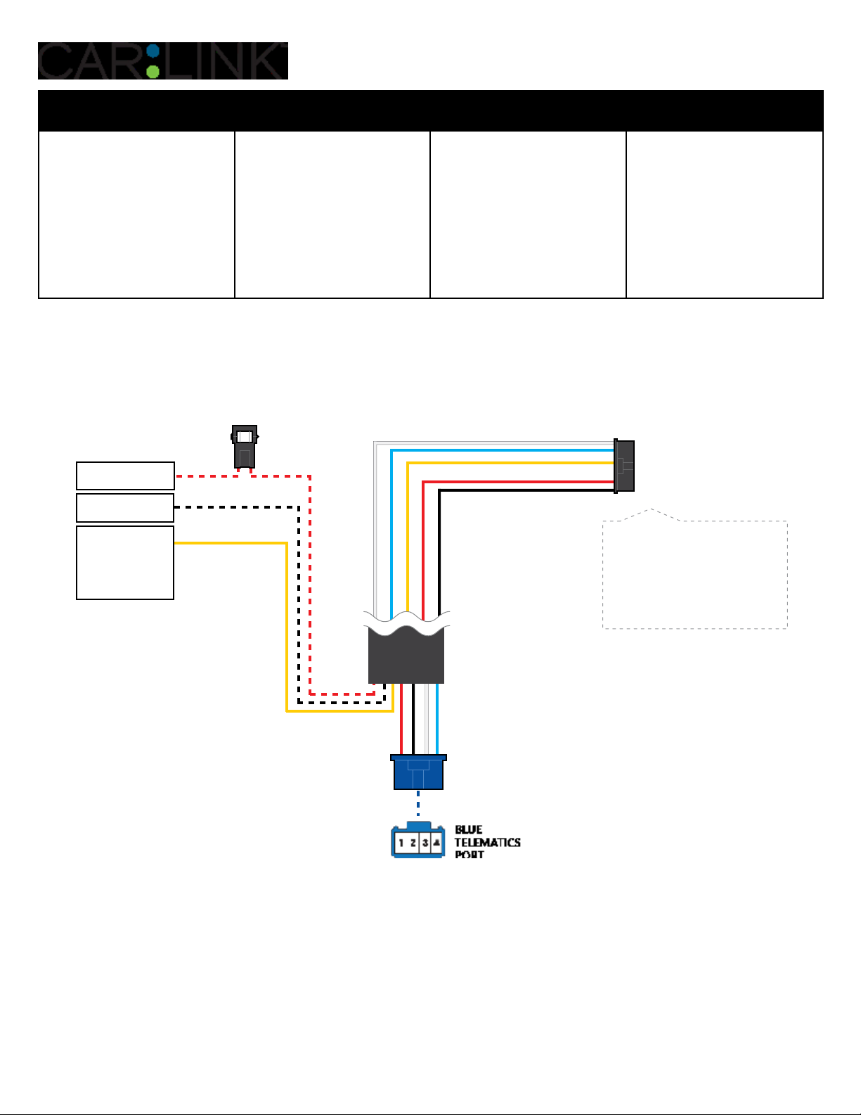
STEP 2. CONNECT
3
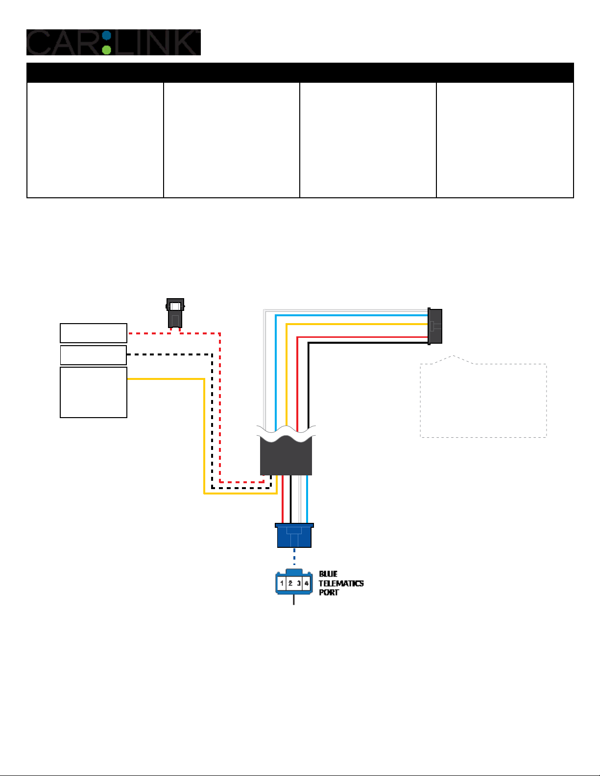
(+) 12V BATTERY
(1)
GROUND
(+) HORN (PULSE)
OR
(+) SIREN (CONSTANT)
ANALOG INPUT SIGNAL
FOR ALARM DETECTION
(1)
Installation:
Data (BLUE)
Data (WHITE)
Ground (BLACK)
+12V Battery (RED)
Alarm(+) (YELLOW)
Place module 3 inches
(minimum) from any metal surface
Orientation: Horizontal; small door
facing upward (as seen in this diagram)
4
(1) Connect only when remote starter is not supplying power to telematics device

INSTALLATION, WIRING & PROGRAMMING GUIDE
STEP 3. NETWORK CONNECTIVITY
Once the telematics module is connected into the remote starter, two LED’s will display to which networks
you are connected to. (See LED Status Reference Chart on last page for details). NOTE: The vehicle may
need to be outside in an open area in order to connect to a cellular and/or GPS network.
STEP 4. ADD A DEVICE/VEHICLE TO AN ACCOUNT
a. Click the “+” sign at the bottom right of the Application screen. This will allow you to temporarily add
your customers device/vehicle to your personal account.
b. Enter the 16 digit “Serial Number” found at the back of the telematic device
(SN: XXXXXX-XXXXXXXXXX) and Click “Submit the code”.
c. You are now in “Test Mode”. Test Mode will allow you up to 4 hours for you to test the newly
installed device. At any time during this 4 hour period, you can exit testing mode and make unit “Ready
for Customer Delivery” by “Releasing the vehicle” or by “Transfering the vehicle” from your account.
NOTE: If you do NOT remove the vehicle from your account, it will automatically be removed from your
account and make the unit “Ready for Customer Delivery”.
STEP 5. PRE-CONFIGURE THE APPLICATION EXPERIENCE FOR YOUR CUSTOMER
a. Click on the newly added vehicle from the vehicle list to enter the control screen (the screen that will al-
low you to control the vehicle’s remote start functions). This will automatically take you to the “Vehicle
Configuration” page for this vehicle. You will be prompt to “Set a Bypass Protocol” to use this device.
Click “Ok”.
b. Now you must set the protocol for the telematic device. When combined with the iDatastart HCx remote
starter previously installed, you must set the protocol to “ADS” and click “ACCEPT” then click “Done” at
the top right corner.
c. Now please allow a moment (About 5 minutes) for the telematic device to update your protocol selec-
tion and reboot. After this wait period it will be available to accept commands from the App. In the
vehicle control screen, the Device Signal icon located above the Stop button will display the connectivity status of your telematic device. If the icon is Grayed out, Please wait, Device is still Oine. If icon is
Green, Device is Online and Ready to go.
d. Then from the top right click on of the Settings section edit the Vehicle name, configure the Auxiliaries
that might have been added if applicable and click ACCEPT when done. Then choose the vehicle to
display inside the control panel in the VEHICLE IMAGE section and click ACCEPT once done.
e. When your configurations are all completed, click “Done” at the top right corner. All Configurations will
take eect.
STEP 6. TEST YOUR DEVICE
When the system is Online you start testing the unit from the vehicle control panel. Test all the application
functions (Start, Stop, Lock, Unlock, Auxiliaries, ETC.) When done with the testing, from the vehicle list you
can “Release” the vehicle. There are 2x dierent method to release it to the new owner. Choosing “release”
will simply remove it from your account and make it “Ready for Customer Delivery”. Choosing “transfer”
will transfer the device to the new owner’s account.
Also make sure that the Owners Card is handed to the New Owner of the vehicle. Doing this will ensure
that the instructions on how to setup their App, Account and Vehicle is done correctly by using the device
serial number located on the sticker axed by the installer at the time of installation.
INSTALLATION, WIRING & PROGRAMMING GUIDE
PARTS REQUIRED FOR INSTALLATION OF : iDATASTART VWx
Telematics device HRN-MCAR-01 iDatastart VWx
STEP 1. CONFIGURE THE REMOTE STARTER
The ADS Weblink (ADS-USB) is required to properly configure the iDatastart VWx remote starter to
accept the telematic device. When flashing the iDatastart VWx remote starter, please ensure to turn ON
the Telematics option from the telematics section and choose “MyCar”.
STEP 2. CONNECT
3
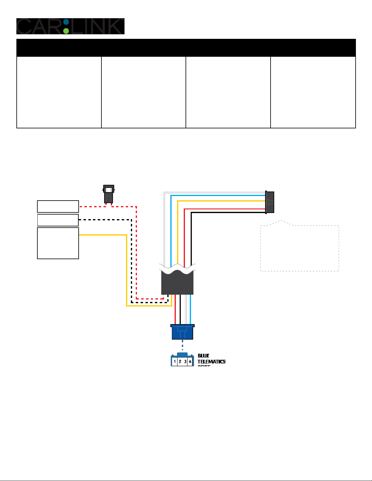
(+) 12V BATTERY
(1)
GROUND
(+) HORN (PULSE)
OR
(+) SIREN (CONSTANT)
ANALOG INPUT SIGNAL
FOR ALARM DETECTION
(1)
Installation:
Data (BLUE)
Data (WHITE)
Ground (BLACK)
+12V Battery (RED)
Alarm(+) (YELLOW)
Place module 3 inches
(minimum) from any metal surface
Orientation: Horizontal; small door
facing upward (as seen in this diagram)
6
(1) Connect only when remote starter is not supplying power to telematics device

INSTALLATION, WIRING & PROGRAMMING GUIDE
STEP 3. NETWORK CONNECTIVITY
Once the telematics module is connected into the remote starter, two LED’s will display to which networks
you are connected to. (See LED Status Reference Chart on last page for details). NOTE: The vehicle may
need to be outside in an open area in order to connect to a cellular and/or GPS network.
STEP 4. ADD A DEVICE/VEHICLE TO AN ACCOUNT
a. Click the “+” sign at the bottom right of the Application screen. This will allow you to temporarily add
your customers device/vehicle to your personal account.
b. Enter the 16 digit “Serial Number” found at the back of the telematic device
(SN: XXXXXX-XXXXXXXXXX) and Click “Submit the code”.
c. You are now in “Test Mode”. Test Mode will allow you up to 4 hours for you to test the newly
installed device. At any time during this 4 hour period, you can exit testing mode and make unit “Ready
for Customer Delivery” by “Releasing the vehicle” or by “Transfering the vehicle” from your account.
NOTE: If you do NOT remove the vehicle from your account, it will automatically be removed from your
account and make the unit “Ready for Customer Delivery”.
STEP 5. PRE-CONFIGURE THE APPLICATION EXPERIENCE FOR YOUR CUSTOMER
a. Click on the newly added vehicle from the vehicle list to enter the control screen (the screen that will al-
low you to control the vehicle’s remote start functions). This will automatically take you to the “Vehicle
Configuration” page for this vehicle. You will be prompt to “Set a Bypass Protocol” to use this device.
Click “Ok”.
b. Now you must set the protocol for the telematic device. When combined with the iDatastart VW remote
starter previously installed, you must set the protocol to “ADS” and click “ACCEPT” then click “Done” at
the top right corner.
c. Now please allow a moment (About 5 minutes) for the telematic device to update your protocol selec-
tion and reboot. After this wait period it will be available to accept commands from the App. In the
vehicle control screen, the Device Signal icon located above the Stop button will display the connectivity status of your telematic device. If the icon is Grayed out, Please wait, Device is still Oine. If icon is
Green, Device is Online and Ready to go.
d. Then from the top right click on of the Settings section edit the Vehicle name, configure the Auxiliaries
that might have been added if applicable and click ACCEPT when done. Then choose the vehicle to
display inside the control panel in the VEHICLE IMAGE section and click ACCEPT once done.
e. When your configurations are all completed, click “Done” at the top right corner. All Configurations will
take eect.
STEP 6. TEST YOUR DEVICE
When the system is Online you start testing the unit from the vehicle control panel. Test all the application
functions (Start, Stop, Lock, Unlock, Auxiliaries, ETC.) When done with the testing, from the vehicle list you
can “Release” the vehicle. There are 2x dierent method to release it to the new owner. Choosing “release”
will simply remove it from your account and make it “Ready for Customer Delivery”. Choosing “transfer”
will transfer the device to the new owner’s account.
Also make sure that the Owners Card is handed to the New Owner of the vehicle. Doing this will ensure
that the instructions on how to setup their App, Account and Vehicle is done correctly by using the device
serial number located on the sticker axed by the installer at the time of installation.
INSTALLATION, WIRING & PROGRAMMING GUIDE
PARTS REQUIRED FOR INSTALLATION OF : iDATASTART BM or BZ
Telematics device HRN-MCAR-01 iDatastart BM or BZ
STEP 1. CONFIGURE THE REMOTE STARTER
The ADS Weblink (ADS-USB) is required to properly configure the iDatastart BM or BZ remote starter
to accept the telematic device. When flashing the iDatastart BM or BZ remote starter, please ensure to
choose the “MyCar” telematics protocol.
STEP 2. CONNECT
3
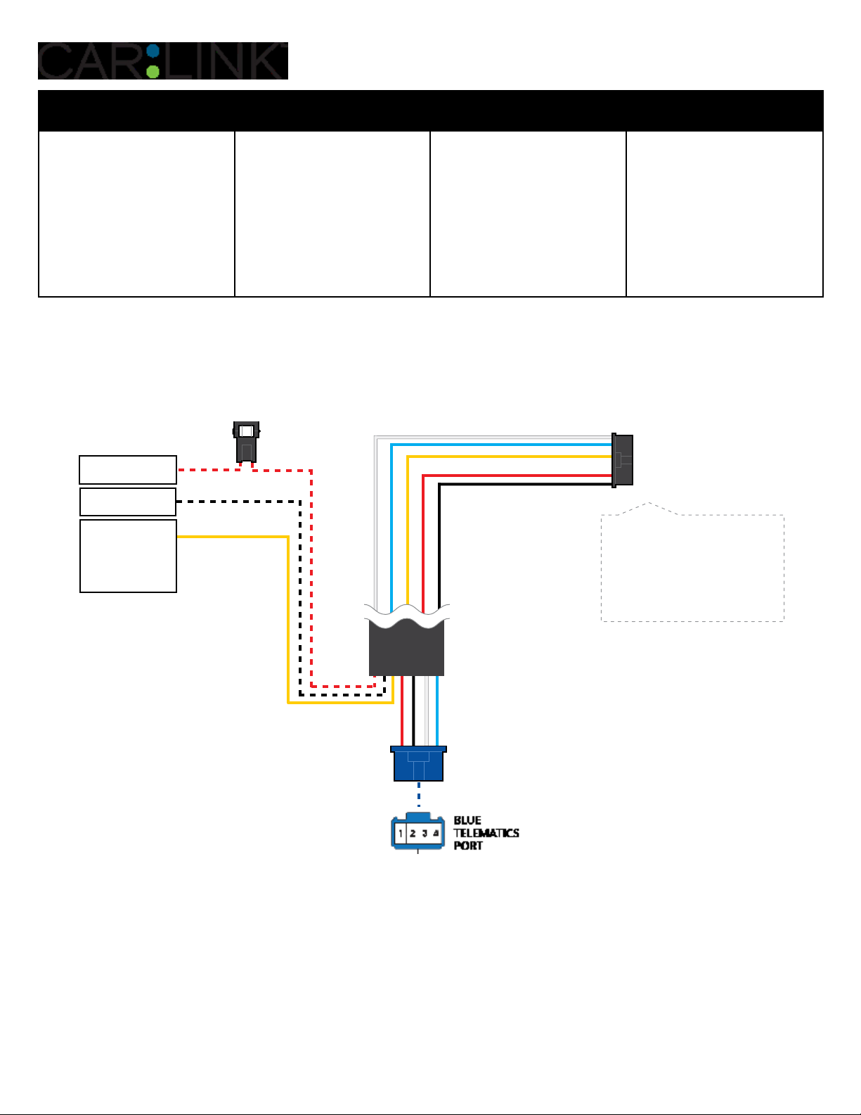
(+) 12V BATTERY
(1)
GROUND
(+) HORN (PULSE)
OR
(+) SIREN (CONSTANT)
ANALOG INPUT SIGNAL
FOR ALARM DETECTION
(1)
Installation:
Data (BLUE)
Data (WHITE)
Ground (BLACK)
+12V Battery (RED)
Alarm(+) (YELLOW)
Place module 3 inches
(minimum) from any metal surface
Orientation: Horizontal; small door
facing upward (as seen in this diagram)
8
(1) Connect only when remote starter is not supplying power to telematics device

INSTALLATION, WIRING & PROGRAMMING GUIDE
STEP 3. NETWORK CONNECTIVITY
Once the telematics module is connected into the remote starter, two LED’s will display to which networks
you are connected to. (See LED Status Reference Chart on last page for details). NOTE: The vehicle may
need to be outside in an open area in order to connect to a cellular and/or GPS network.
STEP 4. ADD A DEVICE/VEHICLE TO AN ACCOUNT
a. Click the “+” sign at the bottom right of the Application screen. This will allow you to temporarily add
your customers device/vehicle to your personal account.
b. Enter the 16 digit “Serial Number” found at the back of the telematic device
(SN: XXXXXX-XXXXXXXXXX) and Click “Submit the code”.
c. You are now in “Test Mode”. Test Mode will allow you up to 4 hours for you to test the newly
installed device. At any time during this 4 hour period, you can exit testing mode and make unit “Ready
for Customer Delivery” by “Releasing the vehicle” or by “Transfering the vehicle” from your account.
NOTE: If you do NOT remove the vehicle from your account, it will automatically be removed from your
account and make the unit “Ready for Customer Delivery”.
STEP 5. PRE-CONFIGURE THE APPLICATION EXPERIENCE FOR YOUR CUSTOMER
a. Click on the newly added vehicle from the vehicle list to enter the control screen (the screen that will al-
low you to control the vehicle’s remote start functions). This will automatically take you to the “Vehicle
Configuration” page for this vehicle. You will be prompt to “Set a Bypass Protocol” to use this device.
Click “Ok”.
b. Now you must set the protocol for the telematic device. When combined with the iDatastart BM or BZ
remote starter previously installed, you must set the protocol to “ADS” and click “ACCEPT” then click
“Done” at the top right corner.
c. Now please allow a moment (About 5 minutes) for the telematic device to update your protocol selec-
tion and reboot. After this wait period it will be available to accept commands from the App. In the
vehicle control screen, the Device Signal icon located above the Stop button will display the connectivity status of your telematic device. If the icon is Grayed out, Please wait, Device is still Oine. If icon is
Green, Device is Online and Ready to go.
d. Then from the top right click on of the Settings section edit the Vehicle name, configure the Auxiliaries
that might have been added if applicable and click ACCEPT when done. Then choose the vehicle to
display inside the control panel in the VEHICLE IMAGE section and click ACCEPT once done.
e. When your configurations are all completed, click “Done” at the top right corner. All Configurations will
take eect.
STEP 6. TEST YOUR DEVICE
When the system is Online you start testing the unit from the vehicle control panel. Test all the application
functions (Start, Stop, Lock, Unlock, Auxiliaries, ETC.) When done with the testing, from the vehicle list you
can “Release” the vehicle. There are 2x dierent method to release it to the new owner. Choosing “release”
will simply remove it from your account and make it “Ready for Customer Delivery”. Choosing “transfer”
will transfer the device to the new owner’s account.
Also make sure that the Owners Card is handed to the New Owner of the vehicle. Doing this will ensure
that the instructions on how to setup their App, Account and Vehicle is done correctly by using the device
serial number located on the sticker axed by the installer at the time of installation.
INSTALLATION, WIRING & PROGRAMMING GUIDE
PARTS REQUIRED FOR INSTALLATION OF : AKX or OEM
Telematics device HRN-MCAR-01 AKX or OEM
STEP 1. CONFIGURE THE REMOTE STARTER
The ADS Weblink (ADS-USB) is required to properly configure the AKX or OEM remote starter to accept
the telematic device. When flashing the AKX or OEM remote starter, please ensure to choose the “MyCar”
telematics protocol.
STEP 2. CONNECT
3
(+) 12V BATTERY
(1)
GROUND
(+) HORN (PULSE)
OR
(+) SIREN (CONSTANT)
ANALOG INPUT SIGNAL
FOR ALARM DETECTION
(1)
Installation:
Data (BLUE)
Data (WHITE)
Ground (BLACK)
+12V Battery (RED)
Alarm(+) (YELLOW)
Place module 3 inches
(minimum) from any metal surface
Orientation: Horizontal; small door
facing upward (as seen in this diagram)
10
(1) Connect only when remote starter is not supplying power to telematics device

INSTALLATION, WIRING & PROGRAMMING GUIDE
STEP 3. NETWORK CONNECTIVITY
Once the telematics module is connected into the remote starter, two LED’s will display to which networks
you are connected to. (See LED Status Reference Chart on last page for details). NOTE: The vehicle may
need to be outside in an open area in order to connect to a cellular and/or GPS network.
STEP 4. ADD A DEVICE/VEHICLE TO AN ACCOUNT
a. Click the “+” sign at the bottom right of the Application screen. This will allow you to temporarily add
your customers device/vehicle to your personal account.
b. Enter the 16 digit “Serial Number” found at the back of the telematic device
(SN: XXXXXX-XXXXXXXXXX) and Click “Submit the code”.
c. You are now in “Test Mode”. Test Mode will allow you up to 4 hours for you to test the newly
installed device. At any time during this 4 hour period, you can exit testing mode and make unit “Ready
for Customer Delivery” by “Releasing the vehicle” or by “Transfering the vehicle” from your account.
NOTE: If you do NOT remove the vehicle from your account, it will automatically be removed from your
account and make the unit “Ready for Customer Delivery”.
STEP 5. PRE-CONFIGURE THE APPLICATION EXPERIENCE FOR YOUR CUSTOMER
a. Click on the newly added vehicle from the vehicle list to enter the control screen (the screen that will al-
low you to control the vehicle’s remote start functions). This will automatically take you to the “Vehicle
Configuration” page for this vehicle. You will be prompt to “Set a Bypass Protocol” to use this device.
Click “Ok”.
b. Now you must set the protocol for the telematic device. When combined with the AKX or OEM remote
starter previously installed, you must set the protocol to “ADS” and click “ACCEPT” then click “Done” at
the top right corner.
c. Now please allow a moment (About 5 minutes) for the telematic device to update your protocol selec-
tion and reboot. After this wait period it will be available to accept commands from the App. In the
vehicle control screen, the Device Signal icon located above the Stop button will display the connectivity status of your telematic device. If the icon is Grayed out, Please wait, Device is still Oine. If icon is
Green, Device is Online and Ready to go.
d. Then from the top right click on of the Settings section edit the Vehicle name, configure the Auxiliaries
that might have been added if applicable and click ACCEPT when done. Then choose the vehicle to
display inside the control panel in the VEHICLE IMAGE section and click ACCEPT once done.
e. When your configurations are all completed, click “Done” at the top right corner. All Configurations will
take eect.
STEP 6. TEST YOUR DEVICE
When the system is Online you start testing the unit from the vehicle control panel. Test all the application
functions (Start, Stop, Lock, Unlock, Auxiliaries, ETC.) When done with the testing, from the vehicle list you
can “Release” the vehicle. There are 2x dierent method to release it to the new owner. Choosing “release”
will simply remove it from your account and make it “Ready for Customer Delivery”. Choosing “transfer”
will transfer the device to the new owner’s account.
Also make sure that the Owners Card is handed to the New Owner of the vehicle. Doing this will ensure
that the instructions on how to setup their App, Account and Vehicle is done correctly by using the device
serial number located on the sticker axed by the installer at the time of installation.
INSTALLATION, WIRING & PROGRAMMING GUIDE
PARTS REQUIRED FOR INSTALLATION OF : ADS-AL-CA / OL-MDB-ALL
Telematics device HRN-MCAR-01
ADS-AL-CA / OL-MDB-ALL
FLCL6HAR,
OL-HRN-LINKR-ALL
(sold Separately)
STEP 1. CONFIGURE THE REMOTE STARTER
The ADS Weblink (ADS-USB) is required to properly configure the ADS-AL-CA or OL-MDB-ALL remote
starter to accept the MyCar telematics device. When flashing the ADS-AL-CA or OL-MDB-ALL remote
starter, please ensure to choose the “MyCar” telematics protocol.
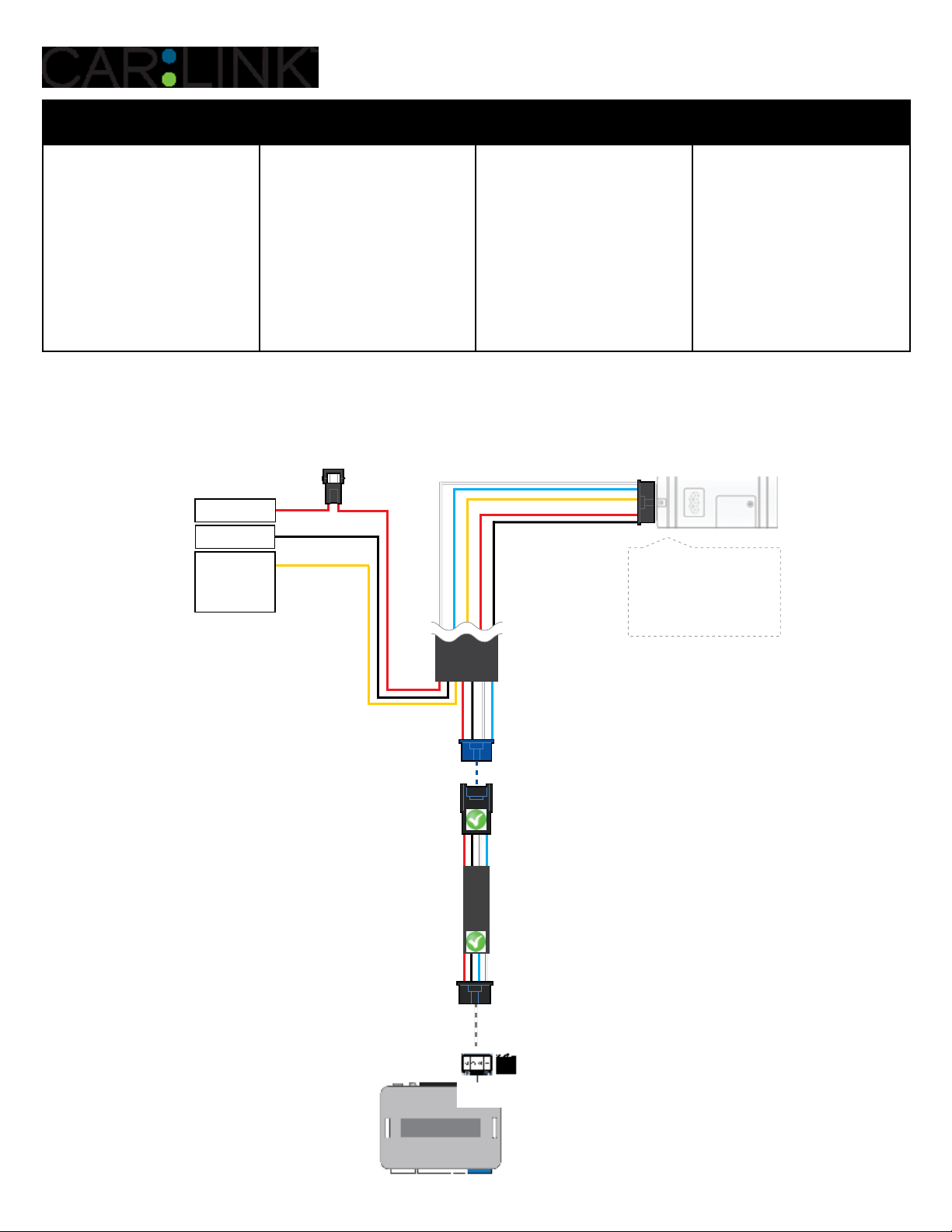
STEP 2. CONNECT
(+) 12V BATTERY
(+) SIREN (CONSTANT)
ANALOG INPUT SIGNAL
FOR ALARM DETECTION
(1)
GROUND
(+) HORN (PULSE)
OR
(1)
3
Installation:
Data (BLUE)
Data (WHITE)
Ground (BLACK)
+12V Battery (RED)
Alarm(+) (YELLOW)
Place module 3 inches
(minimum) from any metal surface
Orientation: Horizontal; small door
facing upward (as seen in this diagram)
12
FLCL6HAR
(1) Connect only when remote starter is not supplying power to telematics device

INSTALLATION, WIRING & PROGRAMMING GUIDE
STEP 3. NETWORK CONNECTIVITY
Once the telematics module is connected into the remote starter, two LED’s will display to which networks
you are connected to. (See LED Status Reference Chart on last page for details). NOTE: The vehicle may
need to be outside in an open area in order to connect to a cellular and/or GPS network.
STEP 4. ADD A DEVICE/VEHICLE TO AN ACCOUNT
a. Click the “+” sign at the bottom right of the Application screen. This will allow you to temporarily add
your customers device/vehicle to your personal account.
b. Enter the 16 digit “Serial Number” found at the back of the device (SN: XXXXXX-XXXXXXXXXX) and
Click “Submit the code”.
c. You are now in “Test Mode”. Test Mode will allow you up to 4 hours for you to test the newly in-
stalled device. At any time during this 4 hour period, you can exit testing mode and make unit “Ready
for Customer Delivery” by “Releasing the vehicle” or by “Transfering the vehicle” from your account.
NOTE: If you do NOT remove the vehicle from your account, it will automatically be removed from your
account and make the unit “Ready for Customer Delivery”.
STEP 5. PRE-CONFIGURE THE APPLICATION EXPERIENCE FOR YOUR CUSTOMER
a. Click on the newly added vehicle from the vehicle list to enter the control screen (the screen that will al-
low you to control the vehicle’s remote start functions). This will automatically take you to the “Vehicle
Configuration” page for this vehicle. You will be prompt to “Set a Bypass Protocol” to use this device.
Click “Ok”.
b. Now you must set the protocol for the MyCar device. When combined with the ADS-AL-CA or OL-MDB-
ALL remote starter previously installed, you must set the protocol to “ADS” and click “ACCEPT” then
click “Done” at the top right corner.
c. Now please allow a moment (About 5 minutes) for the MyCar device to update your protocol selection
and reboot. After this wait period it will be available to accept commands from the App. In the vehicle
control screen, the Device Signal icon located above the Stop button will display the connectivity status
of your MyCar device. If the icon is Grayed out, Please wait, Device is still Oine. If icon is Green, Device
is Online and Ready to go.
d. Then from the top right click on of the Settings section edit the Vehicle name, configure the Auxiliaries
that might have been added if applicable and click ACCEPT when done. Then choose the vehicle to display in the control panel in the VEHICLE IMAGE section and click ACCEPT once done.
e. When your configurations are all completed, click “Done” at the top right corner. All Configurations will
take eect.
STEP 6. TEST YOUR DEVICE
When the system is Online you start testing the unit from the vehicle control panel. Test all the application
functions (Start, Stop, Lock, Unlock, Auxiliaries, ETC.) When done with the testing, from the vehicle list you
can “Release” the vehicle. There are 2x dierent method to release it to the new owner. Choosing “release”
will simply remove it from your account and make it “Ready for Customer Delivery”. Choosing “transfer”
will transfer the device to the new owner’s account.
Also make sure that the MyCar Owners Card is handed to the New Owner of the vehicle. Doing this will
ensure that the instructions on how to setup their App, Account and Vehicle is done correctly by using the
device serial number located on the sticker axed by the installer at the time of installation.
INSTALLATION, WIRING & PROGRAMMING GUIDE
PARTS REQUIRED FOR INSTALLATION OF : CRIMESTOPPER
Telematics device HRN-MCAR-01 CrimeStopper HRN-LLRS-01
Compatible models:
RS-00, RSx-G5, SP402, SP502
STEP 1. CONFIGURE THE REMOTE STARTER
The CrimeStopper remote starter must be configured to accept the telematics device. When programming
the CrimeStopper remote starter, please ensure to select the option indicated “Smart Phone Baud Rate”.
This option MUST BE SET TO 9600baud.
1- Disconnect the HRN-LLRS-01 white connector from Crimestopper Remote Starter
2- Go in the Crimestopper programming and set Baud rate to 9600.
3- Shut ignition O and Disconnect Power from the Crimestopper RS.
5- Wait 10 seconds. Then Reconnect RS and the HRN-LLRS-01 harness for the MyCar.
STEP 2. CONNECT
(+) SIREN (CONSTANT)
ANALOG INPUT SIGNAL
FOR ALARM DETECTION
(+) 12V BATTERY
(1)
GROUND
(+) HORN (PULSE)
OR
3
(1)
Installation:
Data (BLUE)
Data (WHITE)
+12V Battery (RED)
Alarm(+) (YELLOW)
HRN-LLRS-01
Ground (BLACK)
Place module 3 inches
(minimum) from any metal surface
Orientation: Horizontal; small door
facing upward (as seen in this diagram)
14
(1) Connect only when remote starter is not supplying power to telematics device

INSTALLATION, WIRING & PROGRAMMING GUIDE
STEP 3. NETWORK CONNECTIVITY
Once the telematics module is connected into the remote starter, two LED’s will display to which networks
you are connected to. (See LED Status Reference Chart on last page for details). NOTE: The vehicle may
need to be outside in an open area in order to connect to a cellular and/or GPS network.
STEP 4. ADD A DEVICE/VEHICLE TO AN ACCOUNT
a. Click the “+” sign at the bottom right of the Application screen. This will allow you to temporarily add
your customers device/vehicle to your personal account.
b. Enter the 16 digit “Serial Number” found at the back of the telematic device
(SN: XXXXXX-XXXXXXXXXX) and Click “Submit the code”.
c. You are now in “Test Mode”. Test Mode will allow you up to 4 hours for you to test the newly
installed device. At any time during this 4 hour period, you can exit testing mode and make unit “Ready
for Customer Delivery” by “Releasing the vehicle” or by “Transfering the vehicle” from your account.
NOTE: If you do NOT remove the vehicle from your account, it will automatically be removed from your
account and make the unit “Ready for Customer Delivery”.
STEP 5. PRE-CONFIGURE THE APPLICATION EXPERIENCE FOR YOUR CUSTOMER
a. Click on the newly added vehicle from the vehicle list to enter the control screen (the screen that will al-
low you to control the vehicle’s remote start functions). This will automatically take you to the “Vehicle
Configuration” page for this vehicle. You will be prompt to “Set a Bypass Protocol” to use this device.
Click “Ok”.
b. Now you must set the protocol for the telematic device. When combined with the CrimeStopper remote
starter previously installed, you must set the protocol to “ADS” and click “ACCEPT” then click “Done” at
the top right corner.
c. Now please allow a moment (About 5 minutes) for the telematic device to update your protocol selec-
tion and reboot. After this wait period it will be available to accept commands from the App. In the
vehicle control screen, the Device Signal icon located above the Stop button will display the connectivity status of your telematic device. If the icon is Grayed out, Please wait, Device is still Oine. If icon is
Green, Device is Online and Ready to go.
d. Then from the top right click on of the Settings section edit the Vehicle name, configure the Auxiliaries
that might have been added if applicable and click ACCEPT when done. Then choose the vehicle to
display inside the control panel in the VEHICLE IMAGE section and click ACCEPT once done.
e. When your configurations are all completed, click “Done” at the top right corner. All Configurations will
take eect.
STEP 6. TEST YOUR DEVICE
When the system is Online you start testing the unit from the vehicle control panel. Test all the application
functions (Start, Stop, Lock, Unlock, Auxiliaries, ETC.) When done with the testing, from the vehicle list you
can “Release” the vehicle. There are 2x dierent method to release it to the new owner. Choosing “release”
will simply remove it from your account and make it “Ready for Customer Delivery”. Choosing “transfer”
will transfer the device to the new owner’s account.
Also make sure that the Owners Card is handed to the New Owner of the vehicle. Doing this will ensure
that the instructions on how to setup their App, Account and Vehicle is done correctly by using the device
serial number located on the sticker axed by the installer at the time of installation.
CRIMESTOPPER TROUBLESHOOTING
While testing the system, if you are unsuccessful at operating the Remote Starter using the telematic
system it is probably related to the Baud rate not being set correctly as described in Step 1. To overcome
this situation, please follow these steps.
1- Disconnect HRN-LLRS-01 white connector from Crimestopper Remote Starter.
2- Go in Crimestopper RS programming and set back the Baud rate to 115200.
3- Then inside the programming go to Reset all to default (following option right after the Baud Rate).
4- Shut ignition O and Disconnect Power from the Crimestopper RS.
5- Wait 10 seconds. Then Reconnect Crimestopper RS only. DO NOT RECONNECT the telematics device yet.
6- Go back in the Crimestopper RS programming and set Baud rate to 9600.
7 - Shut ignition O and Disconnect Power from the Crimestopper RS.
8- Wait 10 seconds. Then Reconnect Crimestopper RS and HRN-LLRS-01 harness for the telematic device.
9- Wait for the telematic device to be Online (Battery Status and Signal Green).
10- Send a Lock or Unlock command. Parking lights will click in the Crimestopper RS.
11- Then complete all other required programming in the Crimestopper RS.

INSTALLATION, WIRING & PROGRAMMING GUIDE
PARTS REQUIRED FOR INSTALLATION OF : FLASHLOGIC FL-CAN
Telematics device HRN-MCAR-01
Flashlogic FL-CAN
FLCL6HAR
(sold Separately)
STEP 1. CONFIGURE THE REMOTE STARTER
The ADS Weblink (ADS-USB) is required to properly configure the Flashlogic FL-CAN remote starter to
accept the MyCar telematics device. When flashing the Flashlogic FL-CAN remote starter, please ensure to
choose the “ASCL6” telematics protocol.
3
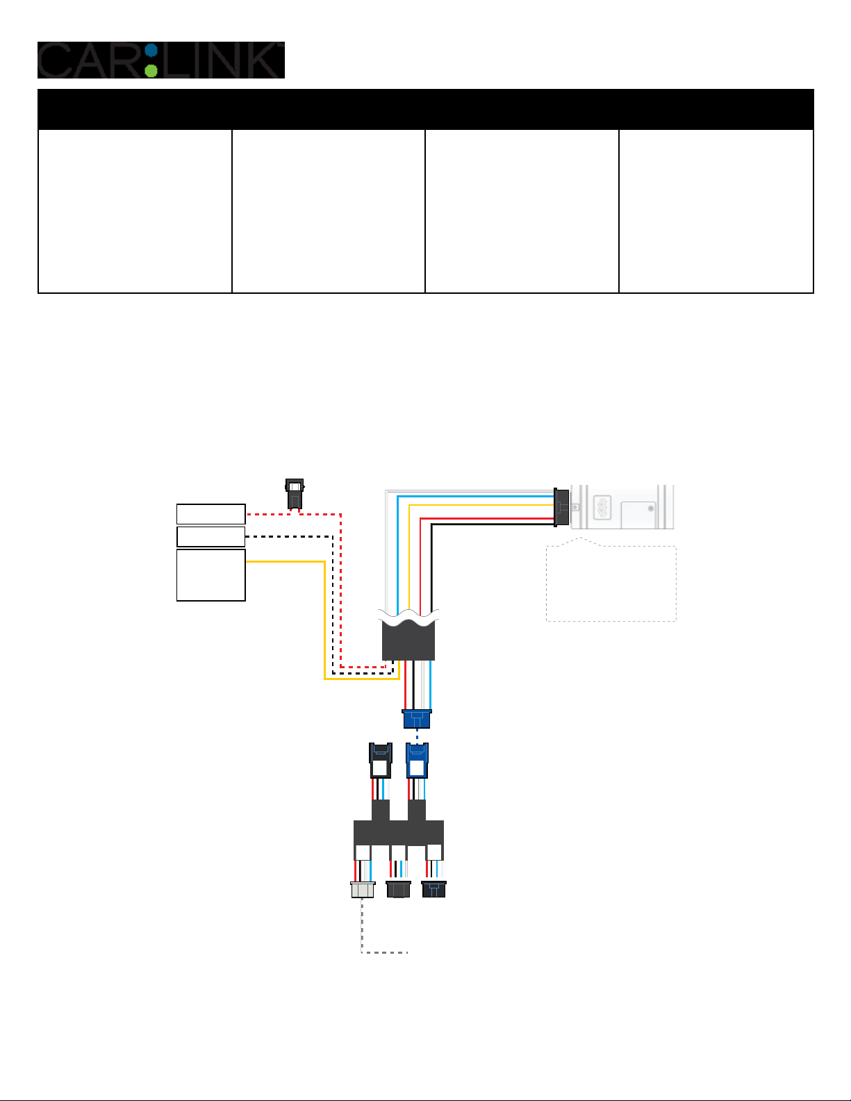
STEP 2. CONNECT
(+) 12V BATTERY
(+) 12V BATTERY
(+) SIREN (CONSTANT)
(+) SIREN (CONSTANT)
ANALOG INPUT SIGNAL
ANALOG INPUT SIGNAL
FOR ALARM DETECTION
FOR ALARM DETECTION
(1)
(1)
GROUND
GROUND
(+) HORN (PULSE)
(+) HORN (PULSE)
OR
OR
(1)
(1)
3
Installation:
Installation:
Place module 3 inches
Data (BLUE)
Data (BLUE)
Data (WHITE)
Data (WHITE)
Ground (BLACK)
Ground (BLACK)
+12V Battery (RED)
+12V Battery (RED)
Alarm(+) (YELLOW)
Alarm(+) (YELLOW)
Place module 3 inches
(minimum) from any metal surface
(minimum) from any metal surface
Orientation: Horizontal; small door
Orientation: Horizontal; small door
facing upward (as seen in this diagram)
facing upward (as seen in this diagram)
16
FLCL6HAR
FLCL6HAR
(1) Connect only when remote starter is not supplying power to telematics device

INSTALLATION, WIRING & PROGRAMMING GUIDE
STEP 3. NETWORK CONNECTIVITY
Once the telematics module is connected into the remote starter, two LED’s will display to which networks
you are connected to. (See LED Status Reference Chart on last page for details). NOTE: The vehicle may
need to be outside in an open area in order to connect to a cellular and/or GPS network.
STEP 4. ADD A DEVICE/VEHICLE TO AN ACCOUNT
a. Click the “+” sign at the bottom right of the Application screen. This will allow you to temporarily add
your customers device/vehicle to your personal account.
b. Enter the 16 digit “Serial Number” found at the back of the device (SN: XXXXXX-XXXXXXXXXX) and
Click “Submit the code”.
c. You are now in “Test Mode”. Test Mode will allow you up to 4 hours for you to test the newly in-
stalled device. At any time during this 4 hour period, you can exit testing mode and make unit “Ready
for Customer Delivery” by “Releasing the vehicle” or by “Transfering the vehicle” from your account.
NOTE: If you do NOT remove the vehicle from your account, it will automatically be removed from your
account and make the unit “Ready for Customer Delivery”.
STEP 5. PRE-CONFIGURE THE APPLICATION EXPERIENCE FOR YOUR CUSTOMER
a. Click on the newly added vehicle from the vehicle list to enter the control screen (the screen that will al-
low you to control the vehicle’s remote start functions). This will automatically take you to the “Vehicle
Configuration” page for this vehicle. You will be prompt to “Set a Bypass Protocol” to use this device.
Click “Ok”.
b. Now you must set the protocol for the MyCar device. When combined with the Flashlogic FL-CAN
remote starter previously installed, you must set the protocol to “ADS” and click “ACCEPT” then click
“Done” at the top right corner.
c. Now please allow a moment (About 5 minutes) for the MyCar device to update your protocol selection
and reboot. After this wait period it will be available to accept commands from the App. In the vehicle
control screen, the Device Signal icon located above the Stop button will display the connectivity status
of your MyCar device. If the icon is Grayed out, Please wait, Device is still Oine. If icon is Green, Device
is Online and Ready to go.
d. Then from the top right click on of the Settings section edit the Vehicle name, configure the Auxiliaries
that might have been added if applicable and click ACCEPT when done. Then choose the vehicle to display in the control panel in the VEHICLE IMAGE section and click ACCEPT once done.
e. When your configurations are all completed, click “Done” at the top right corner. All Configurations will
take eect.
STEP 6. TEST YOUR DEVICE
When the system is Online you start testing the unit from the vehicle control panel. Test all the application
functions (Start, Stop, Lock, Unlock, Auxiliaries, ETC.) When done with the testing, from the vehicle list you
can “Release” the vehicle. There are 2x dierent method to release it to the new owner. Choosing “release”
will simply remove it from your account and make it “Ready for Customer Delivery”. Choosing “transfer”
will transfer the device to the new owner’s account.
Also make sure that the MyCar Owners Card is handed to the New Owner of the vehicle. Doing this will
ensure that the instructions on how to setup their App, Account and Vehicle is done correctly by using the
device serial number located on the sticker axed by the installer at the time of installation.

INSTALLATION, WIRING & PROGRAMMING GUIDE
PARTS REQUIRED FOR INSTALLATION OF : FLASHLOGIC FLRS
Telematics device HRN-MCAR-01 Flashlogic FLRS
STEP 1. CONFIGURE THE REMOTE STARTER
The ADS Weblink (ADS-USB) is required to properly configure the Flashlogic FLRS remote starter to accept
the telematic device. When flashing the Flashlogic FLRS remote starter, please ensure to choose the
“ASCL6” telematics protocol.
STEP 2. CONNECT
3
(+) 12V BATTERY
(1)
GROUND
(+) HORN (PULSE)
OR
(+) SIREN (CONSTANT)
ANALOG INPUT SIGNAL
FOR ALARM DETECTION
(1)
Installation:
Data (BLUE)
Data (WHITE)
Ground (BLACK)
+12V Battery (RED)
Alarm(+) (YELLOW)
Place module 3 inches
(minimum) from any metal surface
Orientation: Horizontal; small door
facing upward (as seen in this diagram)
18
(1) Connect only when remote starter is not supplying power to telematics device

INSTALLATION, WIRING & PROGRAMMING GUIDE
STEP 3. NETWORK CONNECTIVITY
Once the telematics module is connected into the remote starter, two LED’s will display to which networks
you are connected to. (See LED Status Reference Chart on last page for details). NOTE: The vehicle may
need to be outside in an open area in order to connect to a cellular and/or GPS network.
STEP 4. ADD A DEVICE/VEHICLE TO AN ACCOUNT
a. Click the “+” sign at the bottom right of the Application screen. This will allow you to temporarily add
your customers device/vehicle to your personal account.
b. Enter the 16 digit “Serial Number” found at the back of the telematic device
(SN: XXXXXX-XXXXXXXXXX) and Click “Submit the code”.
c. You are now in “Test Mode”. Test Mode will allow you up to 4 hours for you to test the newly
installed device. At any time during this 4 hour period, you can exit testing mode and make unit “Ready
for Customer Delivery” by “Releasing the vehicle” or by “Transfering the vehicle” from your account.
NOTE: If you do NOT remove the vehicle from your account, it will automatically be removed from your
account and make the unit “Ready for Customer Delivery”.
STEP 5. PRE-CONFIGURE THE APPLICATION EXPERIENCE FOR YOUR CUSTOMER
a. Click on the newly added vehicle from the vehicle list to enter the control screen (the screen that will al-
low you to control the vehicle’s remote start functions). This will automatically take you to the “Vehicle
Configuration” page for this vehicle. You will be prompt to “Set a Bypass Protocol” to use this device.
Click “Ok”.
b. Now you must set the protocol for the telematic device. When combined with the Flashlogic FLRS
remote starter previously installed, you must set the protocol to “ADS” and click “ACCEPT” then click
“Done” at the top right corner.
c. Now please allow a moment (About 5 minutes) for the telematic device to update your protocol selec-
tion and reboot. After this wait period it will be available to accept commands from the App. In the
vehicle control screen, the Device Signal icon located above the Stop button will display the connectivity status of your telematic device. If the icon is Grayed out, Please wait, Device is still Oine. If icon is
Green, Device is Online and Ready to go.
d. Then from the top right click on of the Settings section edit the Vehicle name, configure the Auxiliaries
that might have been added if applicable and click ACCEPT when done. Then choose the vehicle to
display inside the control panel in the VEHICLE IMAGE section and click ACCEPT once done.
e. When your configurations are all completed, click “Done” at the top right corner. All Configurations will
take eect.
STEP 6. TEST YOUR DEVICE
When the system is Online you start testing the unit from the vehicle control panel. Test all the application
functions (Start, Stop, Lock, Unlock, Auxiliaries, ETC.) When done with the testing, from the vehicle list you
can “Release” the vehicle. There are 2x dierent method to release it to the new owner. Choosing “release”
will simply remove it from your account and make it “Ready for Customer Delivery”. Choosing “transfer”
will transfer the device to the new owner’s account.
Also make sure that the Owners Card is handed to the New Owner of the vehicle. Doing this will ensure
that the instructions on how to setup their App, Account and Vehicle is done correctly by using the device
serial number located on the sticker axed by the installer at the time of installation.

INSTALLATION, WIRING & PROGRAMMING GUIDE
PARTS REQUIRED FOR INSTALLATION OF : FLASHLOGIC FLRSBA
Telematics device HRN-MCAR-01 Flashlogic FLRSBA
STEP 1. CONFIGURE THE REMOTE STARTER
The ADS Weblink (ADS-USB) is required to properly configure the Flashlogic FLRSBA remote starter to
accept the telematic device. When flashing the Flashogic FLRSBA remote starter, please ensure to turn ON
the Telematics option from the telematics section and choose “Carlink”.
STEP 2. CONNECT
3
(+) 12V BATTERY
(1)
GROUND
(+) HORN (PULSE)
OR
(+) SIREN (CONSTANT)
ANALOG INPUT SIGNAL
FOR ALARM DETECTION
(1)
Installation:
Data (BLUE)
Data (WHITE)
Ground (BLACK)
+12V Battery (RED)
Alarm(+) (YELLOW)
Place module 3 inches
(minimum) from any metal surface
Orientation: Horizontal; small door
facing upward (as seen in this diagram)
20
(1) Connect only when remote starter is not supplying power to telematics device

INSTALLATION, WIRING & PROGRAMMING GUIDE
STEP 3. NETWORK CONNECTIVITY
Once the telematics module is connected into the remote starter, two LED’s will display to which networks
you are connected to. (See LED Status Reference Chart on last page for details). NOTE: The vehicle may
need to be outside in an open area in order to connect to a cellular and/or GPS network.
STEP 4. ADD A DEVICE/VEHICLE TO AN ACCOUNT
a. Click the “+” sign at the bottom right of the Application screen. This will allow you to temporarily add
your customers device/vehicle to your personal account.
b. Enter the 16 digit “Serial Number” found at the back of the telematic device
(SN: XXXXXX-XXXXXXXXXX) and Click “Submit the code”.
c. You are now in “Test Mode”. Test Mode will allow you up to 4 hours for you to test the newly
installed device. At any time during this 4 hour period, you can exit testing mode and make unit “Ready
for Customer Delivery” by “Releasing the vehicle” or by “Transfering the vehicle” from your account.
NOTE: If you do NOT remove the vehicle from your account, it will automatically be removed from your
account and make the unit “Ready for Customer Delivery”.
STEP 5. PRE-CONFIGURE THE APPLICATION EXPERIENCE FOR YOUR CUSTOMER
a. Click on the newly added vehicle from the vehicle list to enter the control screen (the screen that will al-
low you to control the vehicle’s remote start functions). This will automatically take you to the “Vehicle
Configuration” page for this vehicle. You will be prompt to “Set a Bypass Protocol” to use this device.
Click “Ok”.
b. Now you must set the protocol for the telematic device. When combined with the Flashlogic FLRSBA
remote starter previously installed, you must set the protocol to “ADS” and click “ACCEPT” then click
“Done” at the top right corner.
c. Now please allow a moment (About 5 minutes) for the telematic device to update your protocol selec-
tion and reboot. After this wait period it will be available to accept commands from the App. In the
vehicle control screen, the Device Signal icon located above the Stop button will display the connectivity status of your telematic device. If the icon is Grayed out, Please wait, Device is still Oine. If icon is
Green, Device is Online and Ready to go.
d. Then from the top right click on of the Settings section edit the Vehicle name, configure the Auxiliaries
that might have been added if applicable and click ACCEPT when done. Then choose the vehicle to
display inside the control panel in the VEHICLE IMAGE section and click ACCEPT once done.
e. When your configurations are all completed, click “Done” at the top right corner. All Configurations will
take eect.
STEP 6. TEST YOUR DEVICE
When the system is Online you start testing the unit from the vehicle control panel. Test all the application
functions (Start, Stop, Lock, Unlock, Auxiliaries, ETC.) When done with the testing, from the vehicle list you
can “Release” the vehicle. There are 2x dierent method to release it to the new owner. Choosing “release”
will simply remove it from your account and make it “Ready for Customer Delivery”. Choosing “transfer”
will transfer the device to the new owner’s account.
Also make sure that the Owners Card is handed to the New Owner of the vehicle. Doing this will ensure
that the instructions on how to setup their App, Account and Vehicle is done correctly by using the device
serial number located on the sticker axed by the installer at the time of installation.

INSTALLATION, WIRING & PROGRAMMING GUIDE
PARTS REQUIRED FOR INSTALLATION OF : FLASHLOGIC FLCMVW
Telematics device HRN-MCAR-01 Flashlogic FLCMVW
STEP 1. CONFIGURE THE REMOTE STARTER
The ADS Weblink (ADS-USB) is required to properly configure the Flashlogic FLCMVW remote starter to
accept the telematic device. When flashing the Flashlogic FLCMVW remote starter, please ensure to turn
ON the Telematics option from the telematics section and choose “Carlink”.
STEP 2. CONNECT
3
(+) 12V BATTERY
(1)
GROUND
(+) HORN (PULSE)
OR
(+) SIREN (CONSTANT)
ANALOG INPUT SIGNAL
FOR ALARM DETECTION
(1)
Installation:
Data (BLUE)
Data (WHITE)
Ground (BLACK)
+12V Battery (RED)
Alarm(+) (YELLOW)
Place module 3 inches
(minimum) from any metal surface
Orientation: Horizontal; small door
facing upward (as seen in this diagram)
22
(1) Connect only when remote starter is not supplying power to telematics device
 Loading...