

Vox Technologies PSB-810EAV User Manual

1
PSB – 810EAV
Pentium® III, Celeron™, VIA Cyrix® III with
Ethernet, VGA/TV, Audio SBC
Ver 2.x
@Copyright 2000
All Rights Reserved.
Manual first edition March 7, 2000
The information in this document is subject to change without prior
notice in order to improve reliability, design and function and does not
represent a commitment on the part of the manufacturer.
In no event will the manufacturer be liable for direct, indirect, special,
incidental, or consequential damages arising out of the use or inability
to use the product or documentation, even if advised of the possibility
of such damages.
This document contains proprietary information protected by
copyright. All rights are reserved. No part of this manual may be
reproduced by any mechanical, electronic, or other means in any form
without prior written permission of the manufacturer.
Trademarks
PSB-810EAV is registered trademarks of ICP Electronics Inc., IBM PC
is a registered trademark of International Business Machines
Corporation. Intel is a registered trademark of Intel Corporation.
AWARD is registered trademarks of Award Software Internation® Inc.
Other product names mentioned herein are used for identification
purposes only and may be trademarks and/or registered trademarks
of their respective companies.
2
Contents
1. Introduction........................................................ 5
1.1 Specifications ................................................................................... 6
1.2 What You Have ................................................................................ 7
2. Installation .........................................................8
2.1 PSB-810EAV's Layout......................................................................8
2.2 Clear CMOS Setup...........................................................................9
2.3 BIOS Protection Setting................................................................... 9
2.4 System Power On/Off by Keyboard................................................10
2.5 TV OUT Setting..............................................................................10
3. Connection ......................................................11
3.1 Floppy Disk Drive Connector..........................................................11
3.2 PCI E-IDE Disk Drive Connector ....................................................12
3.3 TV Out Connector ..........................................................................12
3.4 Parallel Port....................................................................................13
3.5 Serial Ports.....................................................................................14
3.6 Keyboard/Mouse Connector...........................................................14
3.7 USB Port Connector.......................................................................15

3
3.8 External Switches and Indicators....................................................15
3.9 IrDA Infrared Interface Port ............................................................16
3.10 Fan Connector ...............................................................................17
3.11 PS-ON Connector ..........................................................................17
3.12 LAN RJ45 Connector .....................................................................18
3.13 VGA Connector ..............................................................................18
3.14 Audio Connectors ..........................................................................18
3.15 LAN LED Connector ......................................................................19
4. BIOS Setup ..................................................... 20
4.1 Introduction.....................................................................................20
4.2 Starting Setup.................................................................................20
4.3 Using Setup....................................................................................21
4.4 Main Menu......................................................................................22
4.5 Standard CMOS Setup ..................................................................25
4.6 Advanced BIOS Setup.................................................................... 29
4.7 Advanced Chipset Setup................................................................34
4.8 Integrated Peripherals.................................................................... 38
4.9 Power Management Setup.............................................................42
4.10 PnP/PCI Configuration Setup.........................................................46
4.11 PC Health Status............................................................................48
4.12 Frequency/Voltage Control.............................................................49
4.13 Defaults Menu ................................................................................ 50
4.14 Supervisor/User Password Setting................................................51
4
4.15 Exit Selecting..................................................................................52
Appendix A. Watch-Dog Timer............................. 53
Appendix B. Address Mapping............................. 55
Appendix C. ATX Power Supply...........................57
Appendix D. PSB-810EAV With Intel82559 LAN
Chip .............................................................. 59

5
1
Introduction
Welcome to the PSB-810EAV Pentium® III, Celeron Single
Board Computer. The PSB-810EAV board is a PCI form factor
board, which comes equipped with high performance Pentium®
III, Celeron™,VIA Cyrix®Ⅲ Processor and advanced high
performance multi-mode I/O, designed for the system
manufacturers, integrators, or VARs that want to provide all
the performance, reliability, and quality at a reasonable pr ice.
In addition, the PSB-810EAV provides on chip VGA. The VGA
which provides up to 1600x1200 resolution. The VGA memory
is shar e main memory .
An advanced high performance super AT I/O chip – ITE IT8712
is used in the PSB-810EAV board. Both on-chip UARTs are
compatible with the NS16C550. The parallel port and IDE
interface are compatible with IBM PC/AT architecture's.
PSB-810EAV uses Intel 82559 Fast Ethernet Multifunction PCI
Controller as LAN controller. The 82559 is a fully integrated
10BASE-T/100BASE-TX LAN solution with high performance
networking functions and low power features.
PSB-810EAV uses the advanced INTEL Chipset,810E
which is 100% LPC/PCI software compatible chipset.with PCI
2.2 standard.
6
1.1 Specifications :
•
CPU : Celeron™ 300 - 600Mhz or above Processor
Pentium® III(FC-PGA) 450 - 933Mhz or above Processor
VIA Cyrix® Ⅲ 533MHz or above
•
FSB : Support 66/100/133MHz
•
Bus : PCISA connector with PCI signal only, compatible to Jump
PISA Ver. 1.07
•
DMA channels : 7
•
Interrupt levels : 15
•
Chipset : Intel 810E(810/810DC-100)
•
RAM memory : Single 168-pin DIMM sockets support SDRAM
module. The max memory is up to 256MB.
•
Ultra ATA/33/66 IDE Interface : Two PCI Enhance IDE hard
drives. The south bridge ICH0/ICH supports Ultra ATA/33/66 IDE
interface.
•
Floppy disk driv e inte rface : Single 2.88 MB, 1.44MB, 1.2MB,
720KB, or 360KB floppy disk drive.
•
Two high spe ed Se ries ports : NS16C550 compatible UARTs
•
Bi-directional Paralle l Port
•
Built-in IT8712 to monitor powe r supply v oltage and fan
speed status.
•
IrDA port : Support Se rial Infrared(SIR) and Am plitude Shift
Keyed IR(ASKIR) interface.
•
USB port : Support tw o USB ports for future e xpansion.
•
AC’97 Codec : Support two channel Left/Right Line IN/OUT, MIC
IN, CD IN, and PC beep sound for buzzer.
•
Watch-Dog Time r : can be set by 1,2,3…255 seconds/minutes
period. Reset or NMI was generated when CPU did not periodically
trigger the timer. Your program use INT15 to control the watch-dog
and generate a system reset.
7
•
VGA Controller : Embedded VGA controller, share main
memory . Screen Resolution : up to 1600x1200 in 8-bit
Color at 85Hz Refresh.
•
Intel 82559 Fast Ethernet Multifunction PCI Controller :
IEEE 802.3u Auto-Negotiation support for 10BASET/100BASE-TX standard. Fast back-to-back transmission
support with minimum interframe spacing. Connected to your
LAN t hr oug h RJ 45 conne ct o r.
•
Key board connector
•
CH7008A TV out Function
•
Mouse : PS/2 Mouse Port on-board.
•
Powe r Consumption : + 5V @ 4. 5A, + 12 V @ 0 .2 A (F CP GA PIII-
500 and 128MB DRAM under 3Dmark99 testing)
•
Operating Te mpe rature : 0° ~ 60° C ( CPU needs Cooler)
1.2 What You Have
In addition to this User's Manual, the PSB-810EAV package
includes the following items:
•
PSB-810EAV Celeron™, Pentium® III Single Board
Computer
•
RS-232/Printer Cable x 1
•
FDD Cable x 1
•
IDE HDD DMA66 Cable x 1
•
Audio/RS-232 Cable x 1
•
CD-ROM Driver x 1
•
6-pin Mini-Din to 5-pin Din Keyboard & PS2 Mouse Adapter
Cable x 1
If any of these items is missing or damaged, contact the dealer
from whom you purchased the product. Save the shipping
materials and carton in case you want to ship or store the
product in the future.
8
2
Installation
This chapter describes how to install t he PSB-810EAV. At fir st,
the layout of PSB-810EAV is shown, and the unpacking
information that you should be careful is described. The
jumpers and switches setting for the PSB-810EAV's
configuration, such as CPU type selection, system clock setting,
and watch dog timer, are also included.
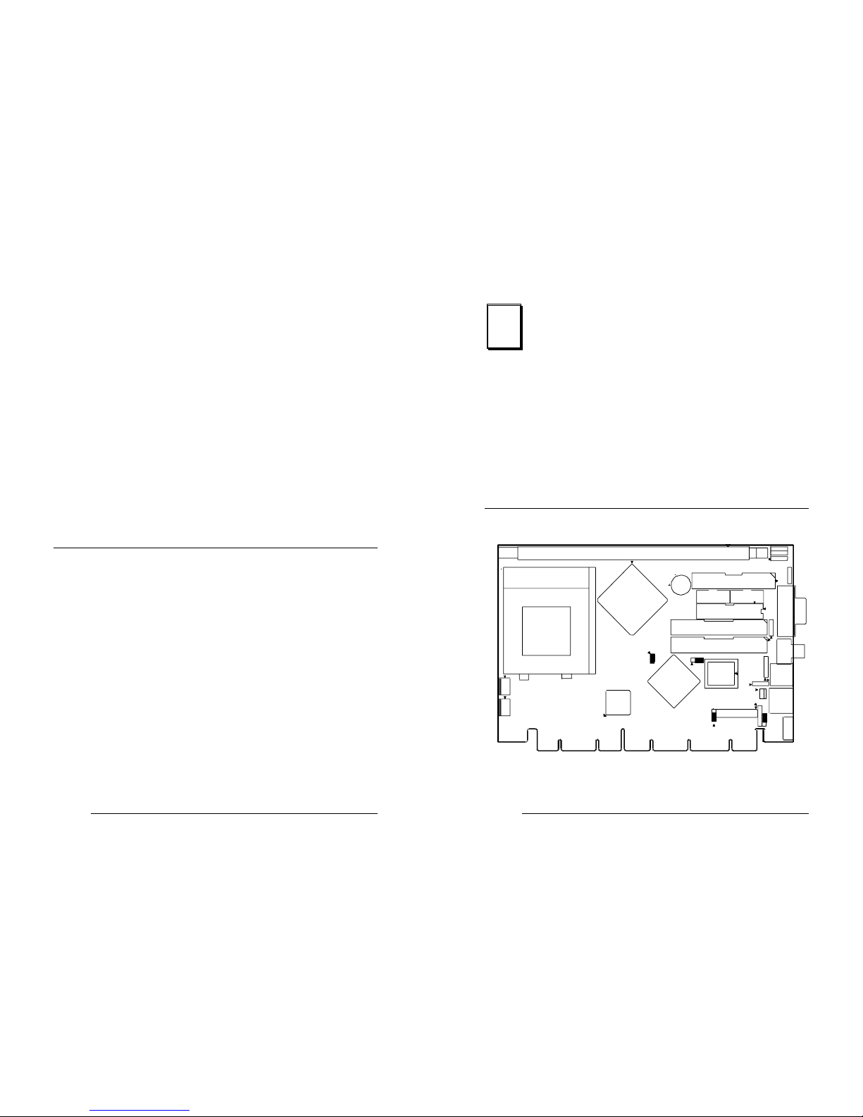
2.1 PSB-810EAV's Layout
CPU
82810E
82801AB
82559
CN23
C
N
2
1
CN1 9
CN7
CN9
CN20
CN8
BZ1
CN11 IDE2
CN13 IDE1
C
N
2
2
C
N
1
4
CN4
CN17
C
N
1
8
JP2
JP7
JP6
CN25
JP8
CN16
CN15
CN10
CN5
CN12
CN6
CN1
CN2
CN26
9
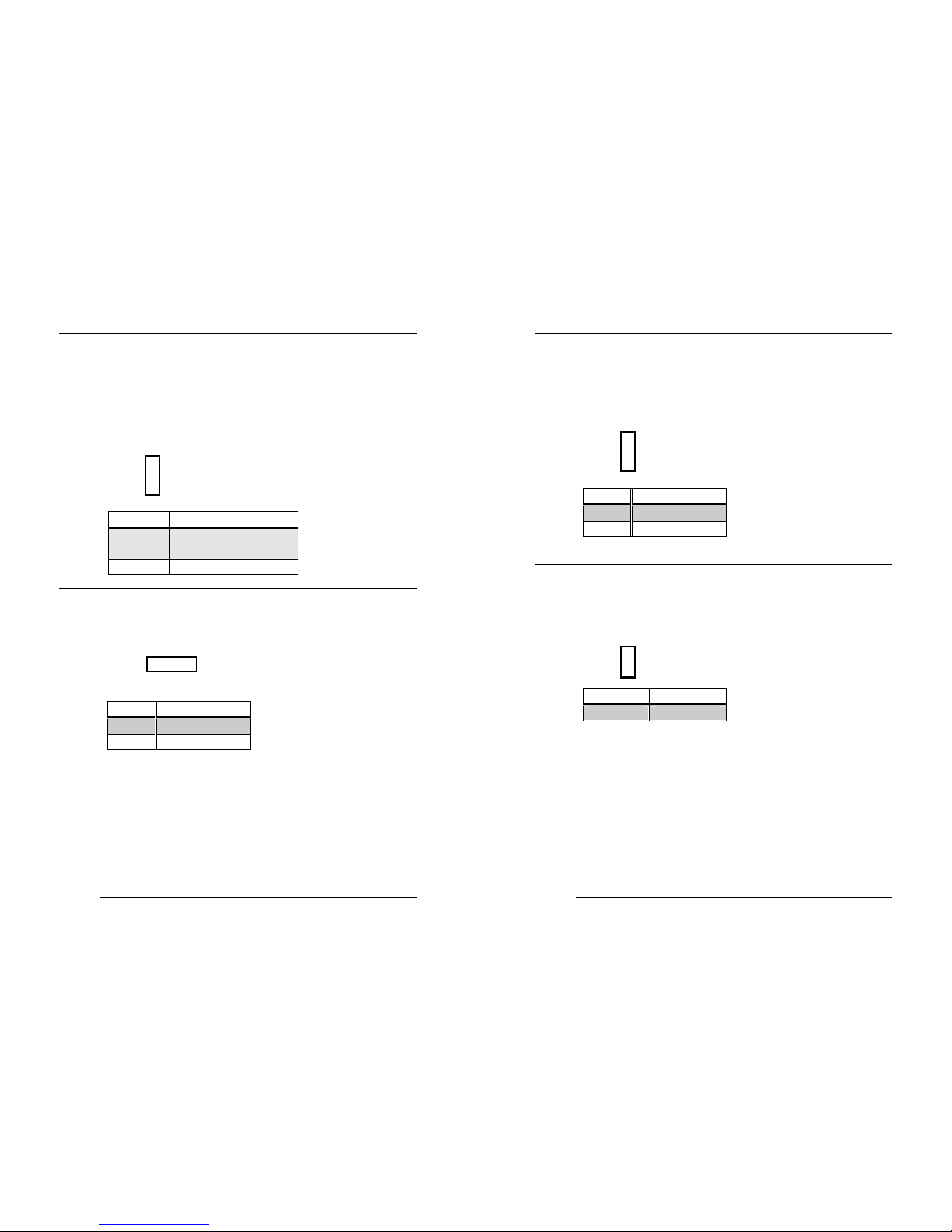
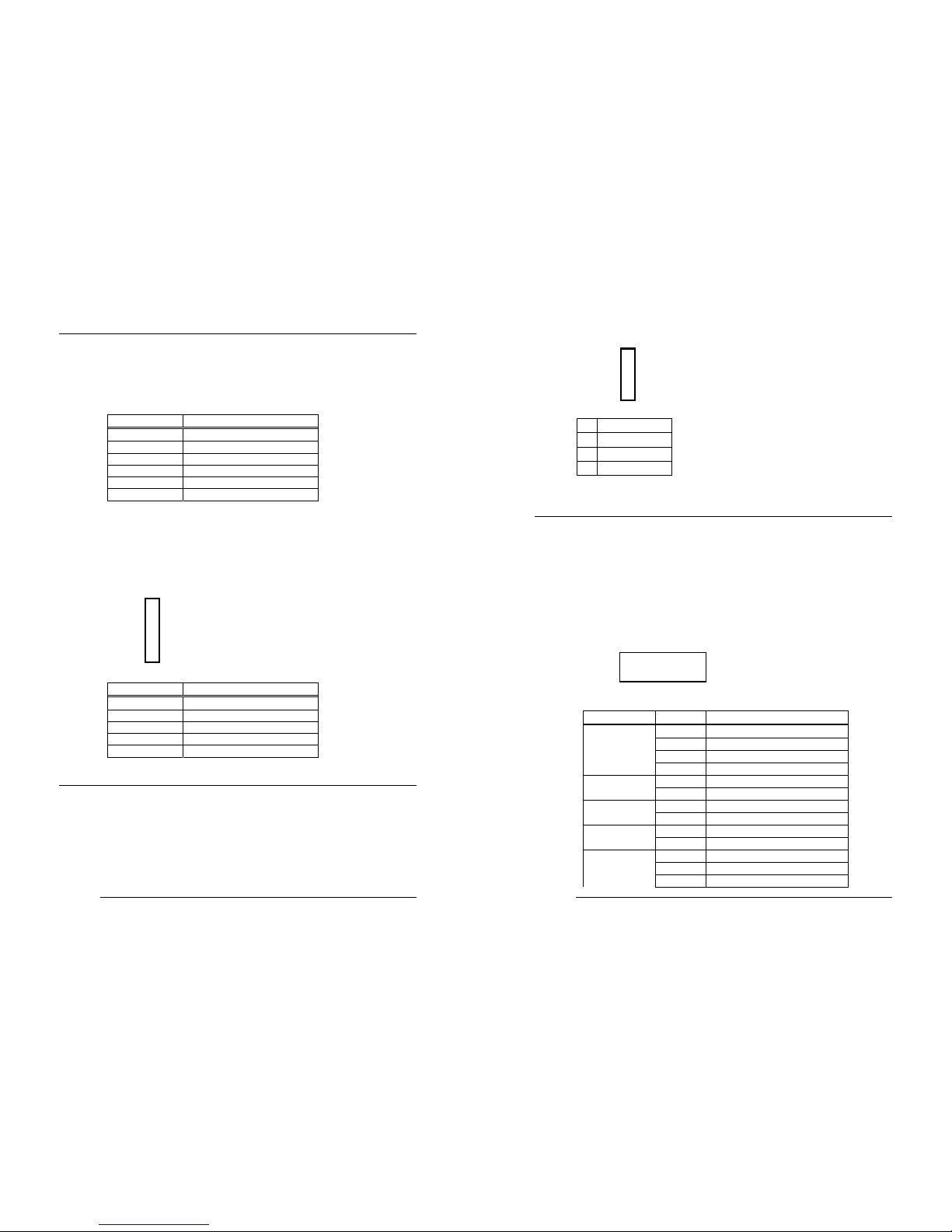
2.2 Clear CMOS Setup
If want to clear the CMOS data (for example you forgot the
password, you should clear the CMOS and then set the
password
again.), you should close the JP7(2-3) about 3 seconds, then
open.
•
JP7 : Clear CMOS Setup
3
2
1
JP7 DESCRIPTION
1-2 Keep CMOS Setup
(Normal Operation)
2-3 Clear CMOS Setup
2.3 BIOS Protection Setting
To protect the bios from writing, place the cap on the location 2-3.
• JP6 : Flash Protection Setting
1 2 3
JP6 DESCRIPTION
2-3 Locked
1-2 Unlocked
10
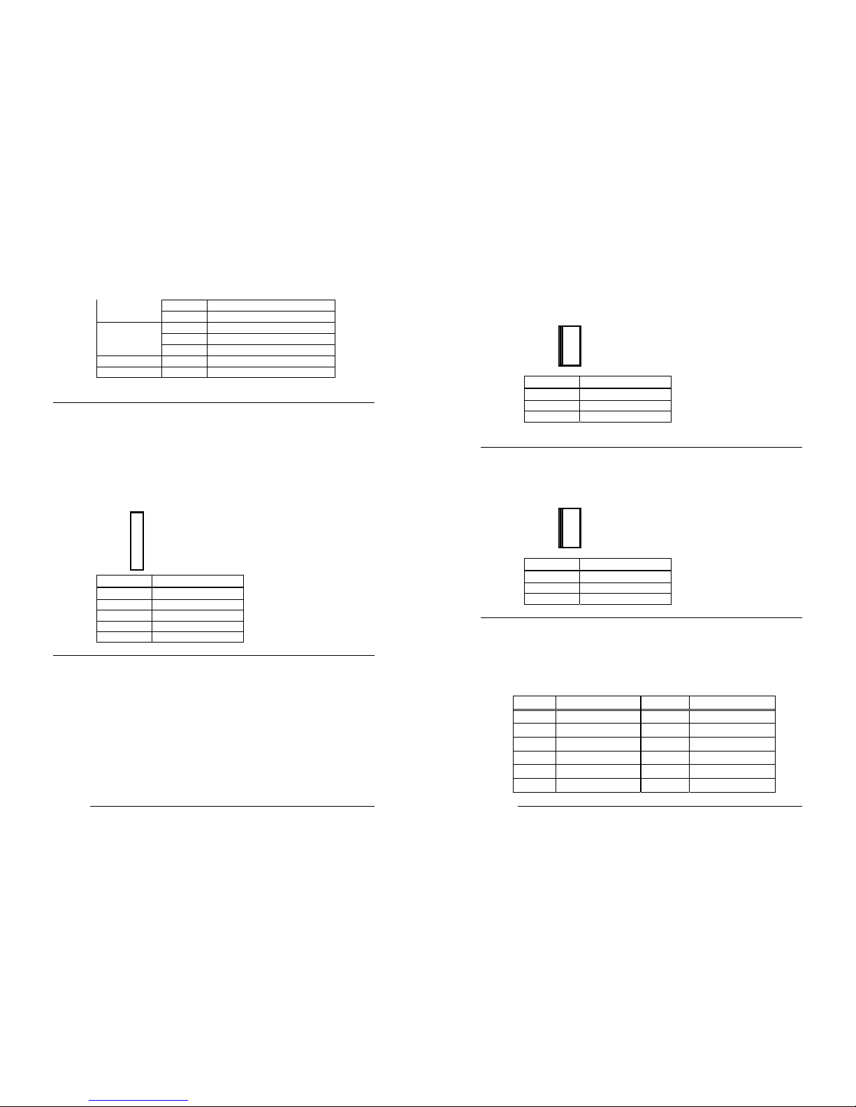
2.4 System Power On by Keyboard when use ATX
as Power Supply
Use keyboard to turn on the system, if ATX power supply are
equipped.
• JP8 : Power On by Keyboard
1
2
3
JP8 DESCRIPTION
1-2 Disabled
2-3 Enabled
2.5 TV OUT Setting
Select the format of TV output signal.
This function is enabled by graphic driver in Windows OS.
• JP2
1
2
OPEN PAL
SHORT NTSC
11
3
Connection
This chapter describes how to connect peripherals, switches
and indicators to the PSB-810EAV board.
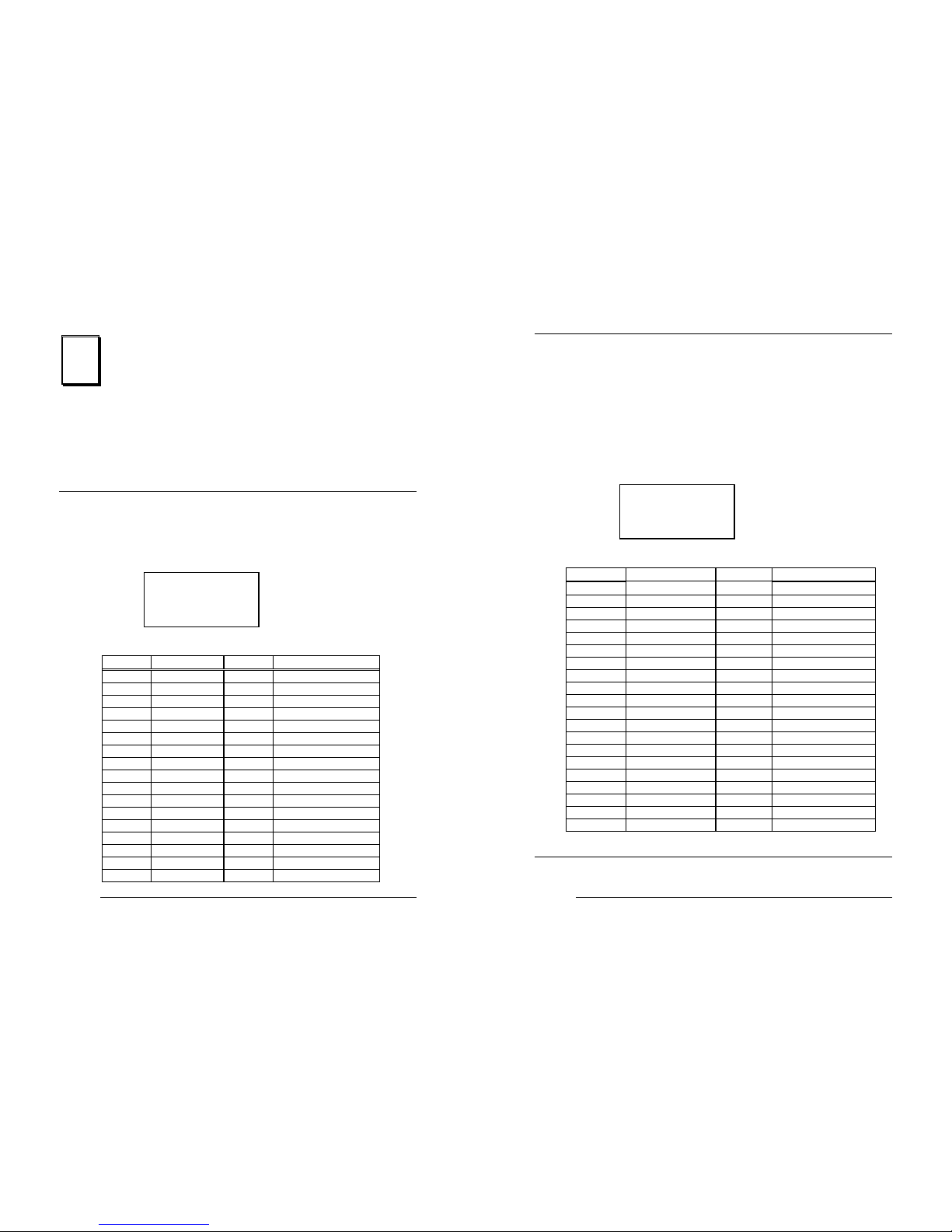
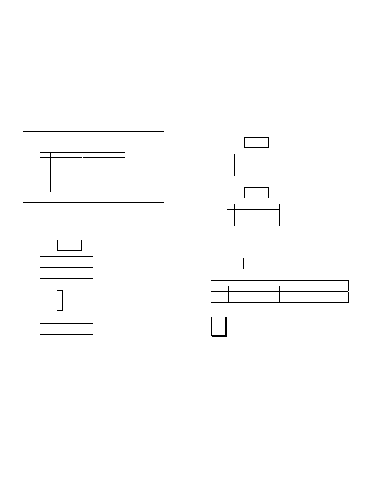
3.1 Floppy Disk Drive Connector
PSB-810EAV board is equipped with a 34-pin daisy-chain driver
connector cable.
•
CN6 : FDC CONNECTO R
33 31 29 … 5 3 1
…
…
34 32 30 … 6 4 2
PIN NO. DESCRIPTION PIN NO. DESCRIPTION
1 GROUND 2 RED UCE WRITE
3 GROUND 4 N/C
5 GROUND 6 N/C
7 GROUND 8 INDEX#
9 GROUND 10 MOTOR ENABLE A#
11 GROUND 12 DRIVE SELECT B#
13 GROUND 14 DRIVE SELECT A#
15 GROUND 16 MOTOR ENABLE B#
17 GROUND 1 8 D IRECTION#
19 GROUND 20 STEP#
21 GROUND 22 WRITE DATA#
23 GROUND 24 WRITE GATE#
25 GROUND 26 TRACK 0#
27 GROUND 28 WRITE PROTECT#
29 N/C 30 READ DATA#
31 GROUND 32 SIDE 1 SELECT#
33 N/C 34 DISK CHANGE#
12
3.2 PCI E-IDE Disk Drive Connector
You can attach four IDE( Integrated Device Electronics) hard disk
drives to t he PSB-810EAV IDE controller .
CN13 (IDE 1) : Primary IDE Connector
CN11 (IDE 2) : Secondary IDE Connector
•
CN13/CN11 : IDE Interface Connector
39 37 35 … 5 3 1
…
…
40 38 36 … 6 4 2
PIN NO. DESCRIPTION PIN NO. DESCRIPTION
1 RESET# 2 GROUND
3 DATA 7 4 DATA 8
5 DATA 6 6 DATA 9
7 DATA 5 8 DATA 10
9 DATA 4 10 DA TA 11
11 DATA 3 12 DA TA 12
13 DATA 2 14 DA TA 13
15 DATA 1 16 DA TA 14
17 DATA 0 18 DA TA 15
19 GROUND 20 N/C
21 N/C 22 GROUND
23 IOW# 24 GROUND
25 IOR# 26 GROUND
27 N/C 28 BA LE - DEFAULT
29 N/C 30 GROUND - D EFAULT
31 INTERRUP T 32 IOCS 16#-DEFAULT
33 SA1 34 N/C
35 SA0 36 SA2
37 HDC CS0# 38 HDC CS1#
39 HDD ACTIVE# 40 GROUND
3.3 TV Out Connector
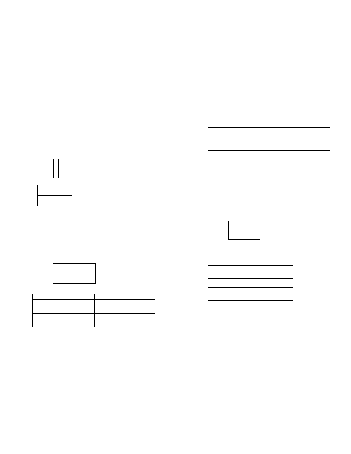
13
The PSB-810EAV built-in tw o TV ports for the future new I/O
bus expansion.
CN18 : RCA Connector(External)
CN17 : S-Video(Internal)
4
3
2
1
1. C
2. GND
3. Y
4. GND
3.4 Parallel Port
This port is usually connected t o a printer, The PSB-810EAV includes
an on-board parallel port, accessed through a 26-pin flat-cable
connector CN1.
•
CN10 : Parallel Port Connector
13 12 11 … 3 2 1
…
…
26 25 24 … 16 15 14
PIN NO. DESCRIPTION PIN NO. DESCRIPTION
1 STROBE# 2 DATA 0
3 DATA 1 4 DATA 2
5 DATA 3 6 DATA 4
7 DATA 5 8 DATA 6
9 DATA 7 10 ACKNOWLEDGE
11 BUSY 12 PAPER EMPTY
14
13 PRINTER SELECT 14 AUTO FORM FEED #
15 ERROR# 16 INITIALIZE
17 PRINTER SELECT LN# 18 GROUND
19 GROUND 20 GROUND
21 GROUND 22 GROUND
23 GROUND 24 GROUND
25 GROUND 26 NC
3.5 Serial Ports
The PSB-810EAV offers two high speed NS16C550 compatible
UARTs with Read/Receive 16 byte FIFO serial ports.
CN5 : COM1
CN12 : COM2
5 4 3 2 1
10 9 8 7 6
• CN5/CN12 : Serial Port 10-pin Connector
PIN NO. DESCRIPTION
1 DATA CARRIER DETECT (DCD)
2 RECE IVE DA TA (RXD)
3 TRANSMIT DATA (TX D)
4 DA TA TERMINA L RE ADY (DTR)
5 GROUND (GND)
6 DATA SET RE ADY (DS R)
7 REQUES T TO SEND (RTS)
8 CLE AR TO SE ND (C TS)
9 RING INDICATOR (RI)
10 N/C
15
3.6 Keyboard/Mouse Connector
The PSB-810EAV provides 6-pin Min-DIN keyboard/mouse
connector.
•
CN23 : 6-pin Mini-DIN Keyboard/Mouse Connector
PIN NO. DESCRIPTION
1 KEYBOARD DATA
2 MOUSE DATA
3 GROUND
4 +5V
5 KEYBOARD CLOCK
6 MOUSE CLOCK
• CN25 : 5-pin External Keyboard Connector
1
2
3
4
5
PIN NO. DESCRIPTION
1 KEYBOARD CLOCK
2 KEYBOARD DATA
3 NC
4 GROUND
5 +5V
3.7 USB Port Connector
The PSB-810EAV built-in tw o USB ports for t he future new I/O
bus expansion.
CN22 : USB 0(External)
CN14 : USB 1(Internal)
16
4
3
2
1
1. VCC
2. DATA-
3. DATA+
4. GROUND
3.8 External Switches and Indicators
There are several external switches and indicators for
monitoring and controlling your CPU board. All the functions are
in the CN19 connector.
CN19 Pin Assignment and Functions :
19 17 … 3 1
…
…
20 18 … 4 2
FUNCTION PIN NO. D ES CRIPTION
1 SPK SIGNAL
3 N/C
5 N/C
SPEAKER
7 VCC
9 POWE R GOOD RESET
10 GROUND
13 LED HDD LED
15 VCC
17 POWER BUTTON POWER
BUTTON
19 GROUND
12 GROUND
14 N/C
ATX POWER
16 PS_ON#
17
18 STANDBY VCC5V
20 STANDBY VCC5V
2 VCC5V
4 N/C
POWER LED
6 GROUND
RESERVE 8 N/C
RESERVE 11 GROUND
3.9 IrDA Infrared Interface Port
The PSB-810EAV built-in a Ir DA port which support Serial
Infrar ed(SI R) or Amplitude Shift Keyed IR(ASKIR) interface.
When use the IrDA port have to set SIR or ASKI R model in the
BIOS’s Peripheral Setup’s COM 2. Then the normal RS-232
COM 2 will be disabled.
• CN15 : IrDA connector
5
4
3
2
1
PIN NO. DESCRIPTION
1 VCC
2 N/C
3 IR-RX
4 Ground
5 IR-TX
3.10 Fan Connector
The PSB-810EAV provides CPU cooling fan connector,
chassis fan connector. These connectors can supply
12V/500mA
to the cooling fan. In the connector there have a “rotation” pin .
The rotation pin is to get the fan’s rotation signal to system. So
the system BIOS could recognize the fan speed. Please note
only specified fan offers the rotation signal.
18
• CN1 : CPU Fan Connector
1
2
3
PIN NO. DESCRIPTION
1 Ground
2 12V
3 Rotation S ignal
3.11 PS-ON Connector
This connector is used to control the ATX power supply.
• CN2 : PS-ON Connector
1
2
3
PIN NO. DESCRIPTION
1 +5V Standby
2 PS-ON
3 Ground
3.12 LAN RJ45 Connector
PSB-810EAV is equipped with a built-in 10/100Mbps Ethernet
Cont r olle r. Y ou can co nnec t it t o your LAN t hr ough RJ 45 LAN
connector. The pin assignments are as following:
• CN16 : LAN RJ45 Connector
PIN NO. DESCRIPTION PIN NO. DESCRIPTION
1 TX+ 7. N/C
2 TX- 8. N/C
3. RX+ 9. Speed +
4. N/C 10. Speed 5 N/C 11. Active +
6. RX- 12. Active -
19
3.13 VGA Connector
• CN2 1 : 15-pin Female Connector
1 RED 2 GREEN
3 BLUE 4 NC
5 GROUND 6 GROUND
7 GROUND 8 GROUND
9 NC 10 GROUND
11 NC 12 DDC DAT
13 HSYNC 14 V SYNC
15 DDCCLK
3.14 Audio Connectors
The AC’97 Codec support several audio functions. The
connectors are described as below.
CN9 : LINE IN
1 2 3 4
1. LEFT SIGNAL
2. GROUND
3. GROUND
4. RIGHT SIGNAL
CN20 : CD IN
4
3
2
1
1. LEFT SIGNAL
2. GROUND
3. GROUND
4. RIGHT SIGNAL
20
CN8 : MIC IN
1 2 3 4
1. MIC IN
2. GROUND
3. GROUND
4. REF
CN7 : Left/Right Audio Output Connector
1 2 3 4
1. LEFT SIGNAL
2. GROUND
3. GROUND
4. RIGHT SIGNAL
3.15 LAN LED Connectors
The pin assignments are as following
CN26 : LAN LED
1 3
2 4
LAN LED
+ - Description LED ON LED OFF LED Flashing
2 1 Speed 100Mbps 10Mbps NA
4 3 Link/Active Link Ok Link Fail Sending or Receiving
4
 Loading...