

Vox Technologies EMB-9670 series, EMB-9673 series User Manual

Part No. 2047967000
EMB-9670/9673 Series
Intel Socket 478/479 Pentium® M/Celeron® M /
Onboard Mobile Intel Celeron 600 MHz 0K L2 Cache
ITX Main Board with AC97 Audio,
Dual 10/100 Base-Tx Ethernets,
VGA, 2 Ch. LVDS and PCI Interface
User’s Manual
1st Ed – 25 April 2005

EMB-9670/9673 Series
2 EMB-9670/9673 Series User’s Manual
FCC Statement
THIS DEVICE COMPLIES WITH PART 15 FCC RULES. OPERATION IS
SUBJECT TO THE FOLLOWING TWO CONDITIONS:
(1) THIS DEVICE MAY NOT CAUSE HARMFUL INTERFERENCE.
(2) THIS DEVICE MUST ACCEPT ANY INTERFERENCE RECEIVED INCLUDING
INTERFERENCE THAT MAY CAUSE UNDESIRED OPERATION.
THIS EQUIPMENT HAS BEEN TESTED AND FOUND TO COMPLY WITH THE LIMITS
FOR A CLASS "A" DIGITAL DEVICE, PURSUANT TO PART 15 OF THE FCC RULES.
THESE LIMITS ARE DESIGNED TO PROVIDE REASONABLE PROTECTION AGAINTST
HARMFUL INTERFERENCE WHEN THE EQUIPMENT IS OPERATED IN A
COMMERCIAL ENVIRONMENT. THIS EQUIPMENT GENERATES, USES, AND CAN
RADIATE RADIO FREQUENCY ENERGY AND, IF NOT INSTATLLED AND USED IN
ACCORDANCE WITH THE INSTRUCTION MANUAL, MAY CAUSE HARMFUL
INTERFERENCE TO RADIO COMMUNICATIONS.
OPERATION OF THIS EQUIPMENT IN A RESIDENTIAL AREA IS LIKELY TO CAUSE
HARMFUL INTERFERENCE IN WHICH CASE THE USER WILL BE REQUIRED TO
CORRECT THE INTERFERENCE AT HIS OWN EXPENSE.
Notice
This guide is designed for experienced users to setup the system within the shortest time.
For detailed information, please always refer to the electronic user's manual.
Copyright Notice
Copyright © 2005 Evalue Technology Inc., ALL RIGHTS RESERVED.
No part of this document may be reproduced, copied, translated, or transmitted in any form
or by any means, electronic or mechanical, for any purpose, without the prior written
permission of the original manufacturer.
Trademark Acknowledgement
Brand and product names are trademarks or registered trademarks of their respective
owners.

User’s Manual
EMB-9670/9673 Series User’s Manual
3
Disclaimer
Evalue Technology Inc. reserves the right to make changes, without notice, to any product,
including circuits and/or software described or contained in this manual in order to improve
design and/or performance. Evalue Technology assumes no responsibility or liability for the
use of the described product(s), conveys no license or title under any patent, copyright, or
masks work rights to these products, and makes no representations or warranties that
these products are free from patent, copyright, or mask work right infringement, unless
otherwise specified. Applications that are described in this manual are for illustration
purposes only. Evalue Technology Inc. makes no representation or warranty that such
application will be suitable for the specified use without further testing or modification.
Life Support Policy
Evalue Technology’s PRODUCTS ARE NOT FOR USE AS CRITICAL COMPONENTS IN
LIFE SUPPORT DEVICES OR SYSTEMS WITHOUT THE PRIOR WRITTEN APPROVAL
OF Evalue Technology Inc.
As used herein:
1. Life support devices or systems are devices or systems which, (a) are intended for
surgical implant into body, or (b) support or sustain life and whose failure to perform,
when properly used in accordance with instructions for use provided in the labeling, can
be reasonably expected to result in significant injury to the user.
2. A critical component is any component of a life support device or system whose failure to
perform can be reasonably expected to cause the failure of the life support device or
system, or to affect its safety or effectiveness.
A Message to the Customer
Evalue Customer Services
Each and every Evalue’s product is built to the most exacting specifications to ensure
reliable performance in the harsh and demanding conditions typical of industrial
environments. Whether your new Evalue device is destined for the laboratory or the factory
floor, you can be assured that your product will provide the reliability and ease of operation
for which the name Evalue has come to be known.
Your satisfaction is our primary concern. Here is a guide to Evalue’s customer services. To
ensure you get the full benefit of our services, please follow the instructions below carefully.

EMB-9670/9673 Series
4 EMB-9670/9673 Series User’s Manual
Technical Support
We want you to get the maximum performance from your products. So if you run into
technical difficulties, we are here to help. For the most frequently asked questions, you can
easily find answers in your product documentation. These answers are normally a lot more
detailed than the ones we can give over the phone. So please consult the user’s manual
first.
To receive the latest version of the user’s manual; please visit our Web site at:
http://www.evalue-tech.com/
If you still cannot find the answer, gather all the information or questions that apply to your
problem, and with the product close at hand, call your dealer. Our dealers are well trained
and ready to give you the support you need to get the most from your Evalue’s products. In
fact, most problems reported are minor and are able to be easily solved over the phone.
In addition, free technical support is available from Evalue’s engineers every business day.
We are always ready to give advice on application requirements or specific information on
the installation and operation of any of our products. Please do not hesitate to call or e-mail
us.
Headquarters
Evalue Technology Inc.
7F, 228, Lian-cheng Road,
Chung Ho City, Taipei,
Taiwan
Tel : +886-2-8226-2345
Fax : +886-2-8226-2777
http://www.evalue-tech.com
E-mail: service@evalue-tech.com
Europe Branch Office
Evalue Europe A/S
Nordre Strandvej 119C,
3150 Hellebaek,
Denmark
Tel : +45-7025-0310
Fax : +45-4975-5026
http://www.evalue-tech.com
E-mail: service.europe@evalue-tech.com
China Branch Office
Evalue Technology Shanghai Inc.
Room 909, 9F, Section B, No.900,
Yisan Road, Caohejing Hi-tech Park,
Shanghai 200233, China
Tel : +86-21-5423-4170
Fax : +86-21-5423-4171
http://www.evalue-tech.com
E-mail: service.china@evalue-tech.com
US Branch Office
Evalue Technology Inc.
Suite 210, 200 Tornillo Way,
Tinton Falls, NJ 07712
USA
Tel: +1-732-578-0200
Fax: +1-732-578-0250
http://www.evalue-tech.com
E-mail: service.usa@evalue-tech.com

User’s Manual
EMB-9670/9673 Series User’s Manual
5
Product Warranty
Evalue warrants to you, the original purchaser, that each of its products will be free from
defects in materials and workmanship for two years from the date of purchase.
This warranty does not apply to any products which have been repaired or altered by
persons other than repair personnel authorized by Evalue, or which have been subject to
misuse, abuse, accident or improper installation. Evalue assumes no liability under the
terms of this warranty as a consequence of such events. Because of Evalue’s high
quality-control standards and rigorous testing, most of our customers never need to use our
repair service. If any of Evalue’s products is defective, it will be repaired or replaced at no
charge during the warranty period. For out-of-warranty repairs, you will be billed according
to the cost of replacement materials, service time, and freight. Please consult your dealer
for more details. If you think you have a defective product, follow these steps:
1. Collect all the information about the problem encountered. (For example, CPU type and
speed, Evalue’s products model name, hardware & BIOS revision number, other
hardware and software used, etc.) Note anything abnormal and list any on-screen
messages you get when the problem occurs.
2. Call your dealer and describe the problem. Please have your manual, product, and any
helpful information available.
3. If your product is diagnosed as defective, obtain an RMA (return material authorization)
number from your dealer. This allows us to process your good return more quickly.
4. Carefully pack the defective product, a complete Repair and Replacement Order Card
and a photocopy proof of purchase date (such as your sales receipt) in a shippable
container. A product returned without proof of the purchase date is not eligible for
warranty service.
5. Write the RMA number visibly on the outside of the package and ship it prepaid to your
dealer.

EMB-9670/9673 Series
6 EMB-9670/9673 Series User’s Manual
Contents
1. Getting started..........................................................................................................10
1.1 Safety Precautions ..................................................................................................10
1.2 Packing List.............................................................................................................10
1.3 Document Amendment History ...............................................................................11
1.4 Manual Objectives...................................................................................................12
1.5 System Specifications .............................................................................................13
1.6 Architecture Overview .............................................................................................15
1.6.1 Block Diagram ................................................................................................................................ 15
1.6.2 Intel RG82855GME and FW82801DB (for EMB-9670) ................................................................. 16
1.6.3 Intel RG82852GM and FW82801DB (for EMB-9673).................................................................... 18
1.6.4 DRAM Interface (Intel RG855GME)............................................................................................... 19
1.6.5 DRAM Interface (Intel RG852GM) ................................................................................................. 19
1.6.6 Chrontel CH7009 TV/DVI Transmitter............................................................................................ 20
1.6.7 PCI Interface .................................................................................................................................. 20
1.6.8 IDE Interface (Bus Master Capability and Synchronous DMA Mode ) .......................................... 20
1.6.9 USB 2.0 .......................................................................................................................................... 20
1.6.10 Ethernet...................................................................................................................................... 21
1.6.11 Winbond W83627HF.................................................................................................................. 23
1.6.12 Fintek F81216D ......................................................................................................................... 24
1.6.13 Compact Flash Interface............................................................................................................ 24
2. Hardware Configuration...........................................................................................25
2.1 Installation Procedure .............................................................................................26
2.1.1 Processor Installation..................................................................................................................... 26
2.1.2 Main Memory.................................................................................................................................. 28
2.2 Jumper and Connector List .....................................................................................30
2.3 Setting Jumpers & Connectors ...............................................................................32
2.3.1 Clear CMOS (JBAT)....................................................................................................................... 32
2.3.2 COM 2 RS-232/422/485 Select (JP1, JP3).................................................................................... 32
2.3.3 COM 2 Pin 9 Signal Select (JP2) ................................................................................................... 33
2.3.4 FSB Select (SW1) .......................................................................................................................... 34
2.3.5 ATX Power Connector (ATXPWR)................................................................................................. 34
2.3.6 CPU Fan Connector (C_FAN1)......................................................................................................35
2.3.7 Signal Description – CPU Fan Connector (C_FAN1).................................................................... 35
2.3.8 RJ-45 Ethernet / USB 0 & 1, 2 & 3 Connectors (CN1, CN2) ......................................................... 35
2.3.9 Parallel Port Connector & Serial Port 1 Connector (CN3) ............................................................. 36
2.3.10 Signal Description – VGA (CN3)................................................................................................ 36

User’s Manual
EMB-9670/9673 Series User’s Manual
7
2.3.11 Audio Connector (CN4).............................................................................................................. 36
2.3.1 Floppy Connector (FLP)................................................................................................................. 37
2.3.2 Signal Description – Floppy Connector (FLP)................................................................................ 37
2.3.3 Primary IDE Connector (IDE_1)..................................................................................................... 38
2.3.4 Secondary IDE Connector (IDE_2)................................................................................................ 38
2.3.5 Signal Description –Primary / Secondary IDE Connector (IDE_1, IDE_2).................................... 39
2.3.6 LCD Inverter Connector (JBKL) ..................................................................................................... 39
2.3.7 Signal Description – LCD Inverter Connector (JBKL).................................................................... 39
2.3.8 CD-ROM Audio Input Connector (JCD) ......................................................................................... 40
2.3.9 Signal Description – LCD Panel Backlight Connector (JCD)......................................................... 40
2.3.10 Serial Port 2 Connector in RS-232 Mode (JCOM2)................................................................... 40
2.3.11 Signal Description – Serial Port 2 Connector in RS-232 Mode (JCOM2).................................. 41
2.3.12 Serial Port 2 Connector in RS-422 Mode (JCOM2)................................................................... 41
2.3.13 Signal Description – Serial Port 2 Connector in RS-422 Mode (JCOM2).................................. 41
2.3.14 Serial Port 2 Connector in RS-485 Mode (JCOM2)................................................................... 42
2.3.15 Signal Description – Serial Port 2 Connector in RS-485 Mode (JCOM2).................................. 42
2.3.16 Serial Port 3 / 4 / 5 / 6 Connector (JCOM36)............................................................................. 43
2.3.17 Serial Port 3 / 4 / 5 / 6 with External DB9 Connector (JCOM36)............................................... 43
2.3.18 Signal Description – Serial Port 3 / 4 / 5 / 6 with External DB9 Connector (JCOM36).............. 44
2.3.19 DI/O Connector (JDIO) .............................................................................................................. 44
2.3.20 Signal Description – DI/O (JDIO)............................................................................................... 44
2.3.21 Front Panel Connector (JFP).....................................................................................................45
2.3.22 Signal Description – Front Panel Connector (JFP).................................................................... 45
2.3.23 IrDA Connector (JIR) ................................................................................................................. 45
2.3.24 Signal Description – IrDA Connector (JIR)................................................................................ 45
2.3.25 LVDS Connector (JLVDS) ......................................................................................................... 46
2.3.26 Signal Description – LVDS Connector (JLVDS)........................................................................ 46
2.3.27 Miscellaneous Setting Connector (JMISC) ................................................................................ 47
2.3.28 Signal Description – Miscellaneous Setting Connector (JMISC)............................................... 47
2.3.29 TMDS Connector (JTMDS)........................................................................................................ 48
2.3.30 Signal Description – TMDS Connector (JTMDS)....................................................................... 48
2.3.31 TV Out Connector (JTV) ............................................................................................................ 49
2.3.32 Signal Description – TV Out Connector (JTV)........................................................................... 49
2.3.33 USB 4 / 5 Connector (JUSB) ..................................................................................................... 49
2.3.34 Signal Description – USB 4 / 5 Connector (JUSB).................................................................... 49
2.3.35 PS/2 Keyboard & Mouse Connector (KB_MS1) ........................................................................ 50
2.3.36 System Fan Connector 1 / 2 (S_FAN1, S_FAN2) ..................................................................... 50
2.3.37 Signal Description – System Fan Connector 1 / 2 (S_FAN1, S_FAN2).................................... 50

EMB-9670/9673 Series
8 EMB-9670/9673 Series User’s Manual
3. BIOS Setup................................................................................................................51
3.1 Starting Setup .........................................................................................................52
3.2 Using Setup ............................................................................................................53
3.3 Getting Help ............................................................................................................54
3.4 In Case of Problems................................................................................................54
3.5 Main Menu ..............................................................................................................55
3.5.1 Standard CMOS Features.............................................................................................................. 56
3.5.2 Advanced BIOS Features .............................................................................................................. 59
3.5.3 Advanced Chipset Features........................................................................................................... 62
3.5.4 Integrated Peripherals.................................................................................................................... 66
3.5.5 Power Management Setup............................................................................................................. 71
3.5.6 PnP / PCI Configuration ................................................................................................................. 73
3.5.7 PC Health Status............................................................................................................................ 74
3.5.8 Frequency / Voltage Control .......................................................................................................... 74
3.5.9 Load Fail-Safe Defaults.................................................................................................................. 75
3.5.10 Load Optimized Defaults............................................................................................................ 75
3.5.11 Set Supervisor / User Password................................................................................................ 76
3.5.12 Save & Exit Setup ...................................................................................................................... 77
3.5.13 Exit Without Save....................................................................................................................... 78
4. Drivers Installation ...................................................................................................79
4.1 Install Chipset Driver (For Intel RG82855GME) ......................................................80
4.2 Install Chipset Driver (For Intel RG82852GM) ........................................................81
4.3 Install Display Driver (For Intel RG82855GME) ......................................................82
4.4 Install Display Driver (For Intel RG82852GM).........................................................83
4.5 Install Audio Driver (For Intel FW82801DB) ............................................................84
4.6 Install Ethernet Driver (For Intel 82562ET)..............................................................85
4.7 Install Ethernet Driver (For Realtek RTL810x, RTL813x Family) ............................86
5. Measurement Drawing .............................................................................................87
Appendix A: BIOS Revisions..........................................................................................89
Appendix B: AWARD BIOS POST Messages ................................................................90
Overview............................................................................................................................91
Post Beep ..........................................................................................................................91
Error Messages .................................................................................................................91
1. CMOS BATTERY HAS FAILED .........................................................................................................91
2. CMOS CHECKSUM ERROR .............................................................................................................91
3. DISK BOOT FAILURE, INSERT SYSTEM DISK AND PRESS ENTER ............................................ 91
4. DISKETTE DRIVES OR TYPES MISMATCH ERROR - RUN SETUP.............................................. 91
5. DISPLAY SWITCH IS SET INCORRECTLY...................................................................................... 92
6. DISPLAY TYPE HAS CHANGED SINCE LAST BOOT ..................................................................... 92

User’s Manual
EMB-9670/9673 Series User’s Manual
9
7. EISA Configuration Checksum Error PLEASE RUN EISA CONFIGURATION UTILITY................... 92
8. EISA Configuration Is Not Complete PLEASE RUN EISA CONFIGURATION UTILITY................... 92
9. ERROR ENCOUNTERED INITIALIZING HARD DRIVE.................................................................... 92
10. ERROR INITIALIZING HARD DISK CONTROLLER ..................................................................... 92
11. FLOPPY DISK CNTRLR ERROR OR NO CNTRLR PRESENT ................................................... 92
12. Invalid EISA Configuration PLEASE RUN EISA CONFIGURATION UTILITY .............................. 93
13. KEYBOARD ERROR OR NO KEYBOARD PRESENT ................................................................. 93
14. Memory Address Error at ... ........................................................................................................... 93
15. Memory parity Error at ................................................................................................................... 93
16. MEMORY SIZE HAS CHANGED SINCE LAST BOOT ................................................................. 93
17. Memory Verify Error at ... ............................................................................................................... 93
18. OFFENDING ADDRESS NOT FOUND ......................................................................................... 93
19. OFFENDING SEGMENT: ..............................................................................................................93
20. PRESS A KEY TO REBOOT ......................................................................................................... 94
21. PRESS F1 TO DISABLE NMI, F2 TO REBOOT ........................................................................... 94
22. RAM PARITY ERROR - CHECKING FOR SEGMENT ... ............................................................. 94
23. Should Be Empty But EISA Board Found PLEASE RUN EISA CONFIGURATION UTILITY....... 94
24. Should Have EISA Board But Not Found PLEASE RUN EISA CONFIGURATION UTILITY ....... 94
25. Slot Not Empty ............................................................................................................................... 94
26. SYSTEM HALTED, (CTRL-ALT-DEL) TO REBOOT ... ................................................................. 94
27. Wrong Board In Slot PLEASE RUN EISA CONFIGURATION UTILITY........................................ 95
28. FLOPPY DISK(S) fail (80) → Unable to reset floppy subsystem................................................... 95
29. FLOPPY DISK(S) fail (40) → Floppy Type dismatch..................................................................... 95
30. Hard Disk(s) fail (80) → HDD reset failed.................................................................................... 95
31. Hard Disk(s) fail (40) → HDD controller diagnostics failed.......................................................... 95
32. Hard Disk(s) fail (20) → HDD initialization error.......................................................................... 95
33. Hard Disk(s) fail (10) → Unable to recalibrate fixed disk............................................................. 95
34. Hard Disk(s) fail (08) → Sector Verify failed................................................................................ 95
35. Keyboard is locked out - Unlock the key. ....................................................................................... 95
36. Keyboard error or no keyboard present. ........................................................................................ 95
37. Manufacturing POST loop.............................................................................................................. 95
38. BIOS ROM checksum error - System halted. ................................................................................ 95
39. Memory test fail. ............................................................................................................................. 95
40. POST Codes .................................................................................................................................. 96
EMB-9670/9673 Series
10 EMB-9670/9673 Series User’s Manual
1. Getting started
1.1 Safety Precautions
Warning!
Always completely disconnect the power cord from your
chassis whenever you work with the hardware. Do not
make connections while the power is on. Sensitive
electronic components can be damaged by sudden power
surges. Only experienced electronics personnel should
open the PC chassis.
Caution!
Always ground yourself to remove any static charge before
touching the CPU card. Modern electronic devices are very
sensitive to static electric charges. As a safety precaution,
use a grounding wrist strap at all times. Place all electronic
components in a static-dissipative surface or static-shielded
bag when they are not in the chassis.
1.2 Packing List
Before you begin installing your single board, please make sure that the
following materials have been shipped:
z 1 x EMB-9670 Series Intel Socket 479 Pentium® M/Celeron® M ITX
Main Board (Onboard Mobile Intel Celeron 600 MHz 0K L2 Cache CPU
for EMB-9673 Series)
z 1 x Quick Installation Guide
z 1 x CD-ROM contains the followings:
— User’s Manual (this manual in PDF file)
— Ethernet driver and utilities
— VGA drivers and utilities
— Audio drivers and utilities
z Cable set includes the followings:
— 1 ATA IDE cable (40-pin, pitch 2.54mm)
— 1 ATA IDE cable (44-pin, pitch 2.0mm)
— 1 FDD cable (34-pin, pitch 2.54mm)
— 1 Serial port cable (10-pin, pitch 2.54mm)
— 1 Serial port cable (40-pin, pitch 2.54mm)

User’s Manual
EMB-9670/9673 Series User’s Manual
11
1.3 Document Amendment History
Revision Date By Comment
1st Apr. 2005 Vicky Lin Initial Release

EMB-9670/9673 Series
12 EMB-9670/9673 Series User’s Manual
1.4 Manual Objectives
This manual describes in detail the Evalue Technology EMB-9670/9673 series Single
Board.
We have tried to include as much information as possible but we have not duplicated
information that is provided in the standard IBM Technical References, unless it proved to
be necessary to aid in the understanding of this board.
We strongly recommend that you study this manual carefully before attempting to interface
with EMB-9670/9673 series or change the standard configurations. Whilst all the necessary
information is available in this manual we would recommend that unless you are confident,
you contact your supplier for guidance.
Please be aware that it is possible to create configurations within the CMOS RAM that
make booting impossible. If this should happen, clear the CMOS settings, (see the
description of the Jumper Settings for details).
If you have any suggestions or find any errors concerning this manual and want to inform
us of these, please contact our Customer Service department with the relevant details.
User’s Manual
EMB-9670/9673 Series User’s Manual
13
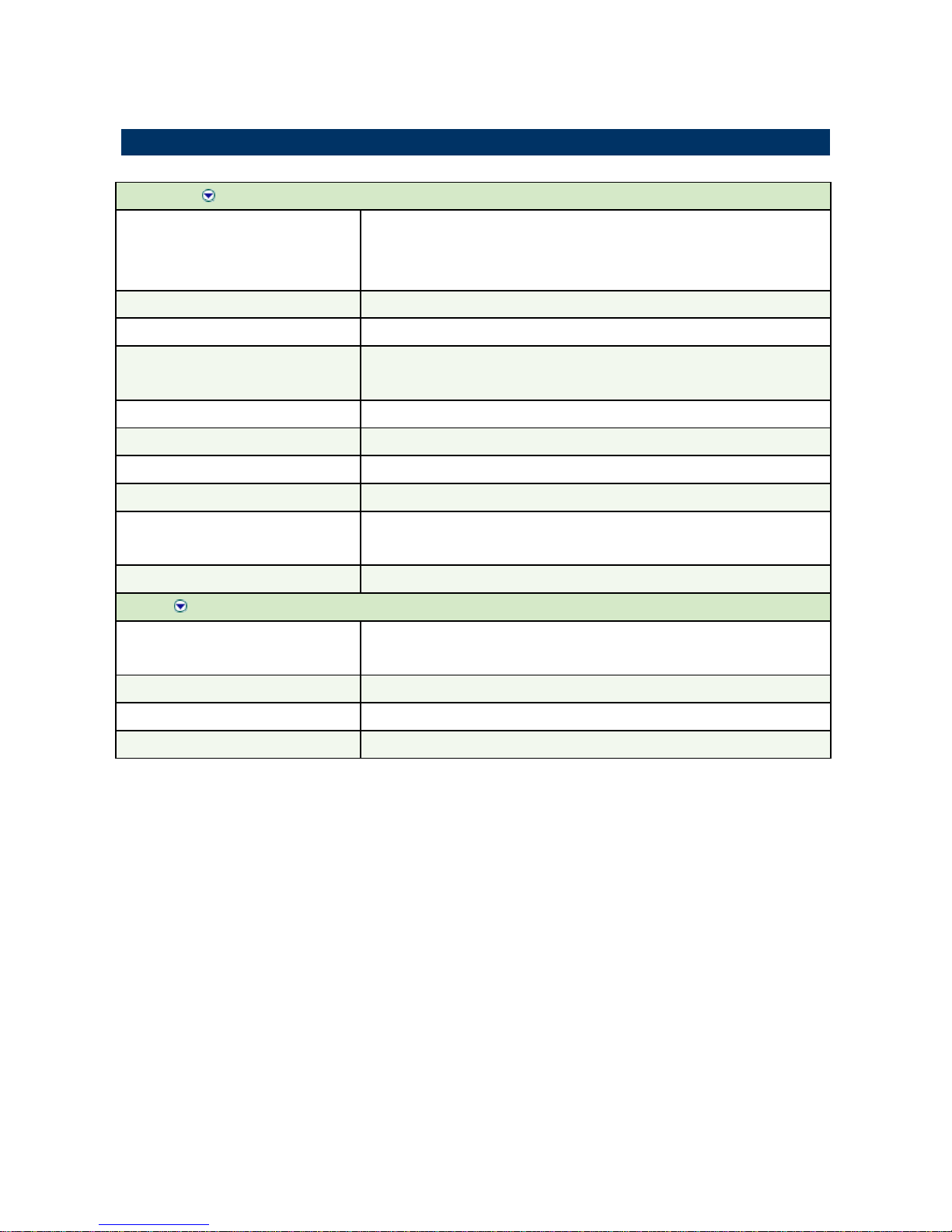
1.5 System Specifications
System
CPU
Supports µFC-PGA 478 / µFC-BGA 479 Intel® Pentium® M / Celeron® M
(Onboard Mobile Intel® Celeron® 600 MHz with 0K L2 Cache CPU for
EMB-9673 only)
FSB
400MHz
BIOS
Award 512 KB Flash BIOS
System Chipset
Intel® RG82855GME GMCH/FW82801DB ICH4
(Intel® RG82852GM GMCH/FW82801DB ICH4 for EMB-9673 only)
I/O Chip
Winbond W83627HF-AW
System Memory
One 184-pin DIMM socket supports up to 1 GB DDR 200/266/333 SDRAM
SSD
One CompactFlash Type I/II socket
Watchdog Timer
Reset: 1 sec.~255 min. ( 1 sec. or 1 min./step)
H/W Status Monitor
Monitoring system temperature, voltage, and cooling fan status. Auto
throttling control when CPU overheats.
Expansion
One PCI slot, one Mini PCI slot
I/O
MIO
4 x EIDE (Ultra DMA 100), 2 x FDD , 1 x LPT, 5 x RS-232, 1 x
RS-232/422/485, 1x K/B, 1 x Mouse
IrDA
115k bps, IrDA 1.0 compliant
USB
6 x USB 2.0 ports
DI/O
16-bit General Purpose I/O for DI and DO
EMB-9670/9673 Series
14 EMB-9670/9673 Series User’s Manual
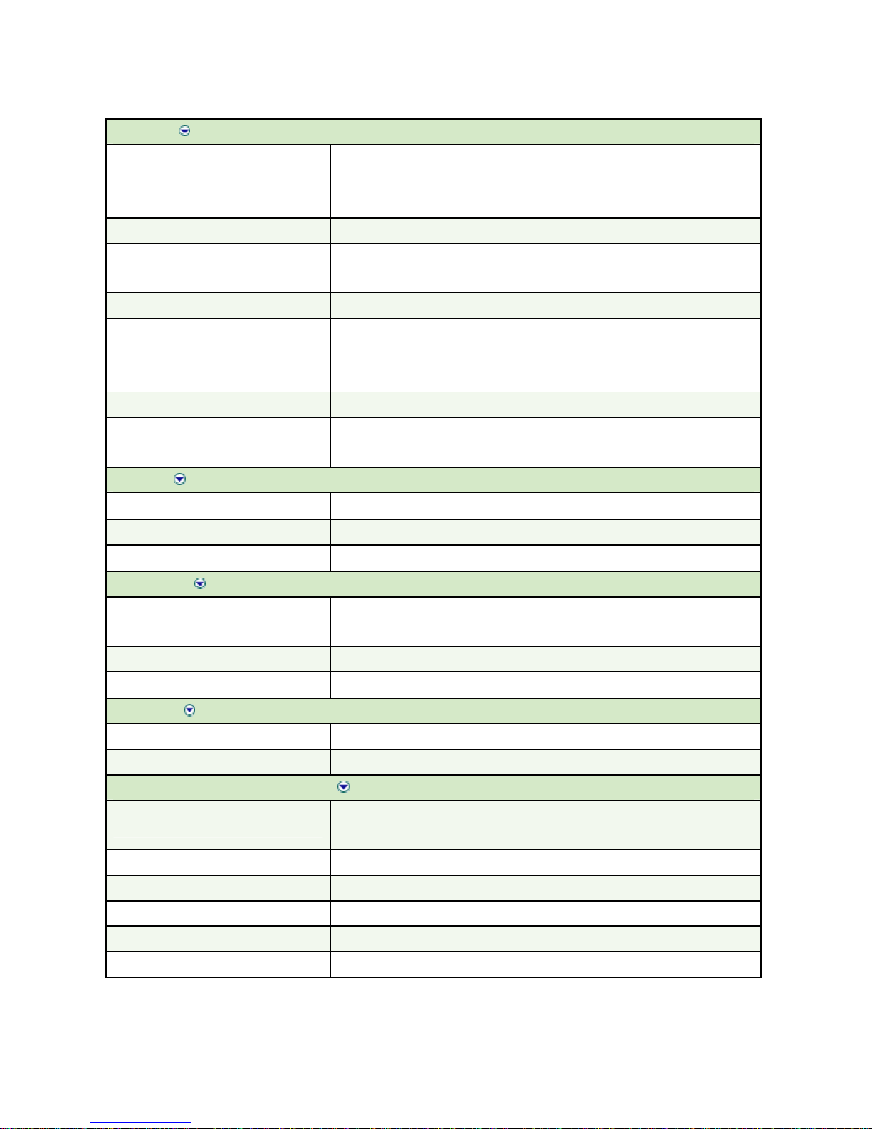
Display
Chipset
Intel® RG82855GME GMCH integrated Extreme Graphics 2 controller
(Intel® RG82852GM GMCH integrated Extreme Graphics controller for
EMB-9673 only)
Display Memory
Intel® DVMT 2.0 supports up to 64 MB video memory
Resolution
CRT mode: 2048 x 1536 @ 16 bpp (75 Hz)
LCD/Simultaneous mode: 2048 x 1536 @ 16 bpp (75 Hz)
VGA/LCD Interface
AGP 4x VGA/LCD interface
LVDS
Intel® RG82855GME supports dual-channel 24-bit LVDS panels
(Intel® RG82852GM supports dual-channel 24-bit LVDS panels for
EMB-9673 only)
DVI
Chrontel CH7009 DVI transmitter up to 135M pixels/ second
TV-Out
Chrontel CH7009 integrated TV encoder supports both NTSC/PAL
Supports both S-video and composite video
Audio
Chipset
Intel® FW82801DB ICH4
AC97 Codec
VIA VT1616 supports 5.1 CH Audio
Audio Interface
Mic in, Line in, CD Audio in, Line out, Rear out and Center/Subwoofer out
Ethernet
Chipset
Intel® 82562ET and Realtek RTL8101L or optional Intel®
82551QM/82551ER
Ethernet Interface
IEEE 802.3u 100Base-Tx Fast Ethernet compatible
Remote Boot ROM
Optional built-in boot ROM in Flash BIOS
Gigabit
Chipset
Intel® 82541PI (Optional)
Ethernet Interface
IEEE 802.3 1000Base-T Fast Ethernet compatible
Mechanical & Environmental
Power Requirement
+ 5 V @ 1.12 A, +12 V @ 0.01 A, + 3.3 V @ 2.72 A (with Intel® Pentium®
M 1.6 GHz & 1 GB DDR SDRAM)
Power Type
ATX
Operation Temperature
0~60® C (32~140® F)
Operating Humidity
0%~90% relative humidity, non-condensing
Size ( L x W )
6.69" x 8.66" (170 mm x 220 mm)
Weight
0.88 lbs (0.4 Kg)
User’s Manual
EMB-9670/9673 Series User’s Manual
15
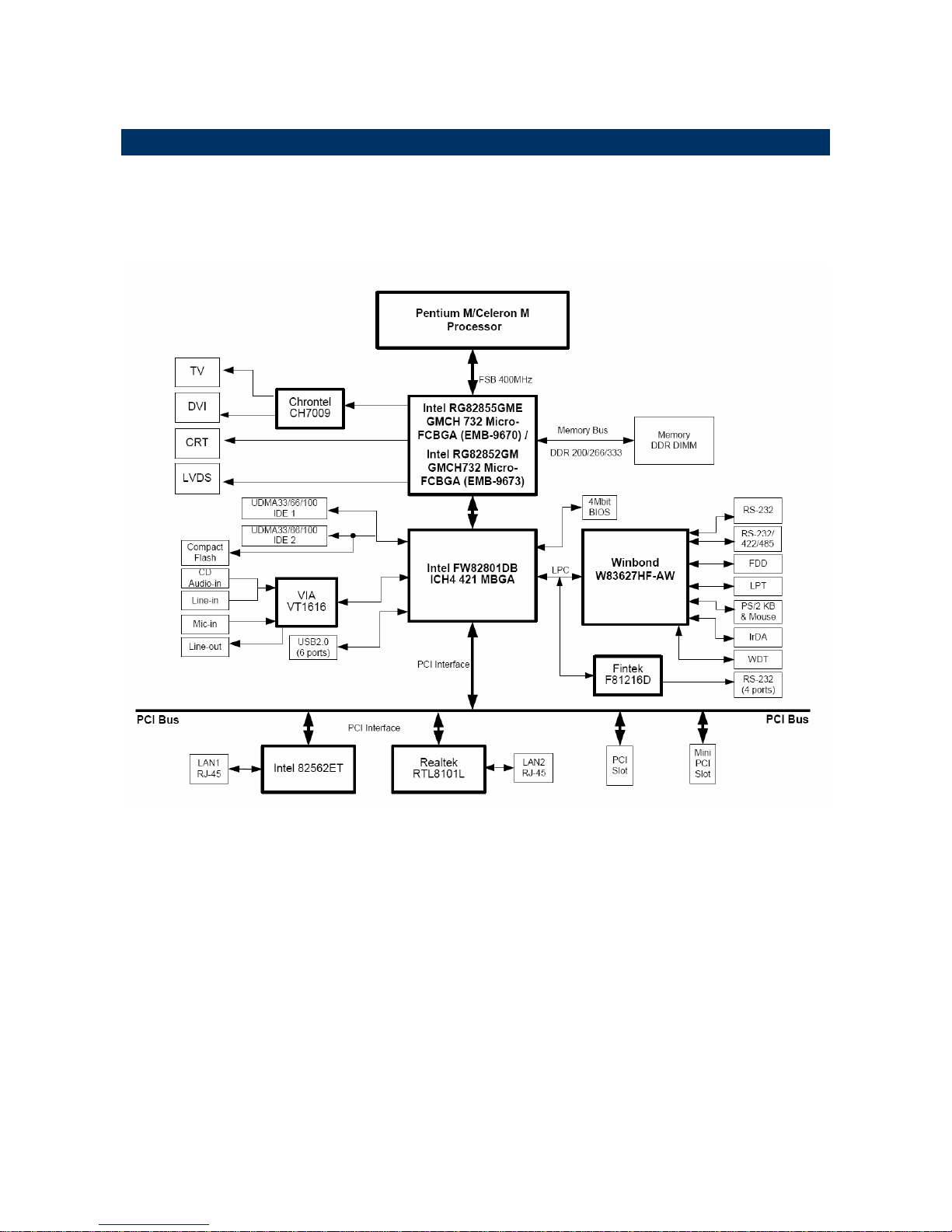
1.6 Architecture Overview
1.6.1 Block Diagram
The following block diagram shows the architecture and main components of
EMB-9670/9673 series.
The following sections provide detail information about the functions provided onboard.

EMB-9670/9673 Series
16 EMB-9670/9673 Series User’s Manual
1.6.2 Intel RG82855GME and FW82801DB (for EMB-9670)
The Intel 855GM/855GME GMCH components provide the processor interface, DDR
SDRAM interface, display interface, and Hub interface. The Intel 855GME also has an
option for AGP external graphics port, in addition to integrated graphics support for added
board flexibility options.
The Intel 855GM GMCH is in a 732-pin Micro-FCBGA package and contains the following
functionality listed below:
• AGTL+ host bus supporting 32-bit host addressing with Enhanced Intel SpeedStep
technology support
• Supports a single channel of DDR SDRAM memory
• System memory supports DDR200/266 MHz (SSTL_2) DDR SDRAM
• Integrated graphics capabilities: Display Core frequency at 133 MHz or 200 MHz
• Render Core frequency at 100 MHz ,133 MHz, and 200 MHz
• Provides supports four display ports: one progressive scan analog monitor, dual
channel LVDS interface and two DVO port.
The Intel 855GME GMCH is in a 732-pin Micro-FCBGA package and contains all features
listed above and the additional functionality list below:
• Display Core frequency at 133 MHz, 200 MHz, or 250 MHz
• Render Core frequency at 100 MHz ,133 MHz, 166 MHz, 200 MHz, or 250 MHz
• System memory supports 200/266/333- MHz (SSTL_2) DDR SDRAM.
• Enhanced Power Management Graphics features
The GMCH IGD provides a highly integrated graphics accelerator delivering high
performance 2D, 3D, and video capabilities. With its interfaces to UMA using a DVMT
configuration, an analog display, a LVDS port, and two digital display ports (e.g. flat panel),
the GMCH can provide a complete graphics solution.
The GMCH also provides 2D hardware acceleration for block transfers of data (BLTs). The
BLT engine provides the ability to copy a source block of data to a destination and perform
raster operations (e.g., ROP1, ROP2, and ROP3) on the data using a pattern, and/or
another destination. Performing these common tasks in hardware reduces CPU load, and
thus improves performance. High bandwidth access to data is provided through the system
memory interface. The GMCH uses Tiling architecture to increase system memory
efficiency and thus maximize effective rendering bandwidth. The Intel 855GM/855GME
GMCH improves 3D performance and quality with 3D Zone rendering technology. The Intel
855GME GMCH also supports Video Mixer rendering and Bi-Cubic filtering.

User’s Manual
EMB-9670/9673 Series User’s Manual
17
The Intel 855GM/855GME GMCH has four display ports, one analog and three digital. With
these interfaces, the GMCH can provide support for a progressive scan analog monitor, a
dedicated dual channel LVDS LCD panel, and two DVO devices. Each port can transmit
data according to one or more protocols. The data that is sent out the display port is
selected from one of the two possible sources, Pipe A or Pipe B.
The Intel 855GM/855GME GMCH have an integrated dual channel LFP Transmitter
interface to support LVDS LCD panel resolutions up to UXGA The display pipe provides
panel up-scaling to fit a smaller source image onto a specific native panel size, as well as
provides panning and centering support. The LVDS port is only supported on Pipe B. The
LVDS port can only be driven by Pipe B, either independently or simultaneously with the
Analog Display port. Spread Spectrum Clocking is supported: center and down spread
support of 0.5%, 1%, and 2.5% utilizing an external SSC clock.
The DVO B/C interface is compliant with the DVI Specification 1.0. When combined with a
DVI compliant external device (e.g. TMDS Flat Panel Transmitter, TV-out encoder, etc.),
the GMCH provides a high-speed interface to a digital or analog display (e.g. flat panel, TV
monitor, etc.). The DVO ports are connected to an external display device. Examples of this
are TV-out encoders, external DACs, LVDS transmitters, and TMDS transmitters. Each
display port has control signals that may be used to control, configure and/or determine the
capabilities of an external device. The GMCH provides two DVO ports that are each
capable of driving a 165-MHz pixel clock at the DVO B or DVO C interface. When DVO B
and DVO C are combined into a single DVO port, then an effective pixel rate of 330 MHz
can be achieved. The DVO B/C ports can be driven by Pipe A or Pipe
B. If driven on Pipe B, then the LVDS port must be disabled.
The ICH4 is a highly integrated multifunctional I/O Controller Hub that provides the
interface to the PCI Bus and integrates many of functions needed in today’s PC platform.
The GMCH and ICH4 communicate over a dedicated hub interface. The 82801DB ICH4
functions and capabilities include:
• PCI Rev. 2.2 compliant with support for 33MHz PCI operations
• Supports up to 6 Request/Grant pairs (PCI slots)
• Power management logic support
• Enhanced DMA controller, interrupt controller, and timer functions
• Integrated IDE controller; Ultra ATA/100/66/33
• USB host interface; 3 host controllers and supports 6 USB ports; includes a EHCI
high-speed 2.0 USB controller

EMB-9670/9673 Series
18 EMB-9670/9673 Series User’s Manual
• Integrated LAN controller
• System Management Bus (SMBus) compatible with most IC devices; ICH4 has both
bus master and slave capability
• AC ’97 2.3 compliant link for audio and telephony codecs; up to 6 channels
• Low Pin Count (LPC) interface
• FWH Interface (FWH Flash BIOS support)
• Alert on LAN* (AOL and AOL2)
1.6.3 Intel RG82852GM and FW82801DB (for EMB-9673)
The Intel 852GM GMCH component provides the processor interface, DDR SDRAM
interface, display interface, and Hub Interface in an Intel 852GM chipset platform. The Intel
852GM GMCH is optimized for the Mobile Intel Pentium 4 Processor-M, Mobile Intel
Celeron processor and Intel Celeron M processor. It supports a single channel of DDR
SDRAM memory. Intel 852GM Chipset contains advanced power management logic. The
Intel 852GM Chipset platform supports the fourth generation mobile I/O Controller Hub to
provide the features required by a mobile platform.
The Intel 852GM GMCH is in a 732-pin Micro-FCBGA package and contains the following
functionality:
• Supports single Intel processor configurations at 400-MHz or 3 GB/s
• 1.2-1.30-V AGTL+ host bus supporting 32-bit host bus addressing with Enhanced
Intel SpeedStep® technology (Intel Celeron M processor and Intel Celeron
Processor do not support Enhanced Intel SpeedStep Technology).
• System Memory supports 200/266-MHz (SSTL_2) DDR DRAM Up to 1 GB (with
256-Mb technology and two SO-DIMMs) of PC1600/2100 DDR SDRAM without
ECC
• Integrated graphics capabilities, including 3D rendering acceleration and 2D
hardware acceleration
• Integrated 350-MHz, 24-bit RAMDAC with pixel resolution up to 1600x1200 at 85-Hz
and up to 1920x1440 @ 60 Hz
• One Dedicated Dual Channel LFP LVDS interface with frequency range of 25 MHz
to 112 MHz (single channel/dual channel) for support up to SXGA+ (1400x1050 @
60 Hz) panel resolutions with maximum pixel depth of 18-bpp
• Integrated PWM (Pulse Width Modulation) interface for LFP backlight inverter
control for panel brightness
• One 165-MHz, 12-bit, DVO interface for TV-out encoder and DVI (LVDS transmitter
and TMDS transmitter) support I2C and DDC channels supported
• Dual Pipe Independent Display with Tri-view support through LFP, DVO, and CRT
• Deeper Sleep state support

User’s Manual
EMB-9670/9673 Series User’s Manual
19
• Distributed arbitration for highly concurrent operation
• Three USB host controllers provide high performance peripherals with 480 Mbps of
bandwidth, while enabling support for up to six USB 2.0 ports. This results in a
significant increase over previous integrated 1-4 port hubs at 12 Mbps
• The latest AC ’97 implementation delivers 20-bit audio for enhanced sound quality
and full surround sound capability. Integrated audio solutions continue to enjoy
success as a very cost-effective, yet high-performance solution
• LAN Connect Interface (LCI) provides flexible network solutions such as 10/100
Mbps Ethernet and 10/100 Mbps Ethernet with LAN manageability
• Dual Ultra ATA/100 controllers, coupled with the Intel® Application Accelerator – a
performance software package – support faster IDE transfers to storage devices
• Intel Application Accelerator software provides additional performance over native
ATA drivers by improving I/O transfer rates and enabling faster O/S load time,
resulting in accelerated boot times
• Communication and Network Riser (CNR) offers flexibility in system configuration
with a baseline feature set that can be upgraded with an audio card, modem card, or
network card
1.6.4 DRAM Interface (Intel RG855GME)
The 855GME GMCH system memory controller directly supports the following:
• One channel of PC1600/2100 DDR SDRAM memory
• One channel of PC1600/2100/2700 DDR SDRAM memory
• DDR SDRAM devices with densities of 128-Mb, 256-Mb, and 512-Mb technology
• Up to 1 GB (512-Mb technology) SDRAM
1.6.5 DRAM Interface (Intel RG852GM)
The 852GM GMCH system memory controller directly supports the following:
• One channel of PC1600/2100 DDR SDRAM memory
• DDR SDRAM devices with densities of 128-Mb, 256-Mb, and 512-Mb technology
• Variable page sizes of 2-kB, 4-kB, 8-kB, and 16-kB. Page size is individually selected
for every row and a maximum of 16 pages may be opened simultaneously

EMB-9670/9673 Series
20 EMB-9670/9673 Series User’s Manual
1.6.6 Chrontel CH7009 TV/DVI Transmitter
The Chrontel CH7009 is a display controller device which accepts a digital graphics input
signal, and encodes and transmits data through a DVI (DFP can also be supported) or TV
output (analog composite, s-video or RGB). The device accepts data over one 12-bit wide
variable voltage data port which supports five different data formats including RGB and
YCrCb.
The DVI processor includes a low jitter PLL for generation of the high frequency serialized
clock, and all circuitries are required to encode, serialize and transmit data. The CH7009
comes in versions able to drive a DVI display at a pixel rate of up to 165MHz, supporting
UXGA resolution displays. No scaling of input data is performed on the data output to the
DVI device.
1.6.7 PCI Interface
The ICH4 PCI interface provides a 33 MHz, Rev. 2.2 compliant implementation. All PCI
signals are 5V tolerant, except PME#. The ICH2 integrates a PCI arbiter that supports up to
six external PCI bus masters in addition to the internal ICH4 requests.
1.6.8 IDE Interface (Bus Master Capability and Synchronous DMA Mode )
The fast IDE interface supports up to four IDE devices providing an interface for IDE hard
disks and ATAPI devices. Each IDE device can have independent timings. The IDE
interface supports PIO IDE transfers up to 16 Mbytes/sec and Ultra ATA transfers up 100
Mbytes/sec. It does not consume any ISA DMA resources. The IDE interface integrates
16x32-bit buffers for optimal transfers.
The ICH4’s IDE system contains two independent IDE signal channels. They can be
electrically isolated independently. They can be configured to the standard primary and
secondary channels (four devices). There are integrated series resistors on the data and
control lines.
Access to these controllers is provided by two standard IDC 40-pin connectors.
1.6.9 USB 2.0
The ICH4 contains an Enhanced Host Controller Interface (EHCI) compliant host controller
that supports USB high-speed signaling. High-speed USB 2.0 allows data transfers up to
480Mb/s which is 40 times faster than full-speed USB. The ICH4 also contains three
Universal Host Controller Interface (UHCI) controllers that support USB full-speed and
low-speed signaling.
The ICH4 supports 6 USB 2.0 ports. All six USB ports are high-speed, full-speed, and
low-speed capable. ICH4’s port-routing logic determines whether a USB port is controlled
by one of the UHCI controllers or by the EHCI controller.

User’s Manual
EMB-9670/9673 Series User’s Manual
21
1.6.10 Ethernet
1.6.10.1 ICH4 LAN Controller
ICH4’s integrated LAN Controller includes a 32-bit PCI controller that provides enhanced
scatter-gather bus mastering capabilities and enables the LAN Controller to perform
high-speed data transfers over the PCI bus. Its bus master capabilities enable the
component to process high level commands and perform multiple operations, this lowers
processor utilization by off-loading communication tasks from the processor. Two large
transmit and receive FIFOs of 3 KB each help prevent data under runs and overruns while
waiting for bus accesses. This enables the integrated LAN Controller to transmit data with
minimum inter frame spacing (IFS).
The LAN Controller can operate in either full duplex or half duplex mode. In full duplex
mode the LAN Controller adheres with the IEEE 802.3x Flow Control specification. Half
duplex performance is enhanced by a proprietary collision reduction mechanism.
The integrated LAN controller also includes an interface to a serial (4-pin) EEPROM. The
EEPROM provides power-on initialization for hardware and software and software
configuration parameters.
From a software perspective, the integrated LAN controller appears to reside on the
secondary side of the ICH4’s virtual PCI to PCI Bridge. This is typically Bus 1, but may be
assigned a different number, depending on system configuration.
The following summarizes the ICH4 LAN controller features:
• Compliance with Advanced Configuration and Power Interface and PCI Power
Management Standard.
• Support for wake-up on interesting packets and link status change
• Support for remote power-up using Wake on LAN (WOL) technology
• Deep power-down no de support
• Support of Wired for management (WfM) Rev 2.0
• Backward compatible software with 82447, 82558 and 82559
• TCP/UDP checksum off load capabilities
• Support for intel’s Adaptive Technology

EMB-9670/9673 Series
22 EMB-9670/9673 Series User’s Manual
1.6.10.2 Realtek RTL8101L Ethernet Controller
The Realtek RTL8101L is a highly integrated and cost-effective single-chip Fast Ethernet
controller. Featuring an MC'97 interface, the device is able to provide a combo-solution for
LAN and software modem applications. It is equipped with a PCI and Boot ROM share
interface (Realtek patent pending) for both EPROM and Flash Memory to provide
maximum network security and ease of management.
The RTL8101L offers an ACPI (Advanced Configuration Power Interface) management
function to provide efficient power management for advanced operating systems with
OSPM (Operating System Directed Power Management). A remote wake-up function is
also provided by support to Magic Packet, Link Change, and Wake-up Frame to increase
cost-efficiency in network maintenance and management. In addition, it supports analog
Auto Power-down and provides an auxiliary power auto-detect function to further save
power.
1.6.10.3 Intel 82551ER Ethernet Controller (Optional)
The Intel® 82551ER integrated 10BASE-T/100BASE-TX Ethernet Controller expands the
family of Intel® 8255x controllers. As part of Intel’s fourth generation of fully integrated Fast
Ethernet MAC/PHY solutions, the 82551ER is optimized for low-cost, embedded
applications. The 82551ER provides excellent performance with offloading of TCP, UDP
and IP checksums. Its optimized 32-bit interface and efficient scatter-gather bus mastering
capabilities enable the controller to perform high-speed data transfers over the PCI bus.
These capabilities accelerate the processing of high-level commands and operations,
lowering CPU utilization. The device’s architecture enables efficient data flow from the bus
interface unit to the 3KB transmit and receive FIFOs, providing the perfect balance between
the wire and system bus. In addition, multiple priority queues augment Quality of Service
(QoS) performance. The 82551ER is pin-compatible with the Intel® 82559ER Fast Ethernet
controller, and it is layout compatible with Intel® 82540 Gigabit Ethernet controller.
Intel-supported 82551ER drivers run on the standard Intel® 82551QM Fast Ethernet
PCI/CardBus Controller, providing OEMs an upgrade path to the 82551QM for additional
features and increased functionality.

User’s Manual
EMB-9670/9673 Series User’s Manual
23
1.6.10.4 Intel 82541PI Gigabit Ethernet Controller (Optional)
The Intel® 82541PI Gigabit Ethernet Controller provides optimized Gigabit networking for
power-sensitive designs, such as mobile PC applications. This highly efficient controller,
with enhanced power management, consumes less than 1.0W of power at Gigabit speeds.
When no signal is detected on the wire, the controller reduces power consumption by
switching to 100 or 10 and powering down the physical-layer circuitry (PHY). When a signal
is detected, the controller automatically negotiates the connection to Gigabit, if available.
To reduce the battery drain, the controller automatically switches the link to 100Mbps
operation when on battery power.
The Intel 82541PI Gigabit Ethernet Controller enhances secure manageability and system
health monitoring over the LAN with support for IPMI 1.5, ASF 2.0 and Advanced Pass
Through. For IPMI designs, the on-board SMBus port can pass management traffic through
the controller to a management device, such as a Baseboard Management Controller
(BMC). Alternatively, ASF 2.0 provides manageability without the cost burden of external
hardware via standardized interfaces. ASF 2.0 circuitry provides advanced system health
and security alerting plus authenticated remote power control capabilities.
With built-in power management capabilities and enhanced manageability, the Intel
82541PI Gigabit Ethernet Controller can help extend battery life for mobile PC users, giving
your designs a competitive edge for tomorrow's mobile PCs.
1.6.11 Winbond W83627HF
The Winbond W83627F/HF is made to fully comply with Microsoft PC98 and PC99
Hardware Design Guide. Moreover, W83627F/HF is made to meet the specification of
PC98/PC99’s requirement in the power management: ACPI and DPM (Device Power
Management). Super I/O chip provides features as the following:
• Meet LPC Spec. 1.0
• Support LDRQ# (LPC DMA), SERIRQ (serial IRQ)
• Include all features of Winbond I/O W83977TF and W83977EF
• Integrate Hardware Monitor functions
• Compliant with Microsoft PC98/PC99 Hardware Design Guide.
• Support DPM (Device Power Management), ACPI
• Programmable configuration settings
• Single 24 or 48 MHz clock input

EMB-9670/9673 Series
24 EMB-9670/9673 Series User’s Manual
1.6.12 Fintek F81216D
The F81216D mainly provides 3 pure UART ports and one UART + IR port through LPC.
Each UART includes 16-byte send/receive FIFO, a programmable baud rate generator,
complete modem control capability and an interrupt system. The features are as followings:
• Support LPC interface
• Totally provides 4 UART ports (3 x Pure UART, 1 x UART + IR)
• 1 Watch dog timer with SDTOUT# signal
• 1 Frequency input 24/48 MHz
• Powered by 3Vcc
• 48-LQFP (7mm x 7mm)
1.6.13 Compact Flash Interface
A Compact Flash type II connector is connected to the secondary IDE controller. The
Compact Flash storage card is IDE compatible. It is an ideal replacement for standard IDE
hard drives. The solid-state design offers no seek errors even under extreme shock and
vibration conditions. The Compact Flash storage card is extremely small and highly suitable
for rugged environments, thus providing an excellent solution for mobile applications with
space limitations. It is fully compatible with all consumer applications designed for data
storage PC card, PDA, and Smart Cellular Phones, allowing simple use for the end user.
The Compact Flash storage card is O/S independent, thus offering an optimal solution for
embedded systems operating in non-standard computing environments. The Compact
Flash storage card is IDE compatible and offers various capacities.

User’s Manual
EMB-9670/9673 Series User’s Manual
25
2. Hardware
Configuration
EMB-9670/9673 Series
26 EMB-9670/9673 Series User’s Manual
2.1 Installation Procedure
This chapter explains you the instructions of how to setup your system.
1. Turn off the power supply.
2. Insert the DIMM module (be careful with the orientation).
3. Insert all external cables for hard disk, floppy, keyboard, mouse, USB etc. except for flat
panel. A CRT monitor must be connected in order to change CMOS settings to support
flat panel.
4. Connect power supply to the board via the ATXPWR.
5. Turn on the power.
6. Enter the BIOS setup by pressing the delete key during boot up. Use the “LOAD BIOS
DEFAULTS” feature. The Integrated Peripheral Setup and the Standard CMOS Setup
Window must be entered and configured correctly to match the particular system
configuration.
7. If TFT panel display is to be utilized, make sure the panel voltage is correctly set before
connecting the display cable and turning on the power.
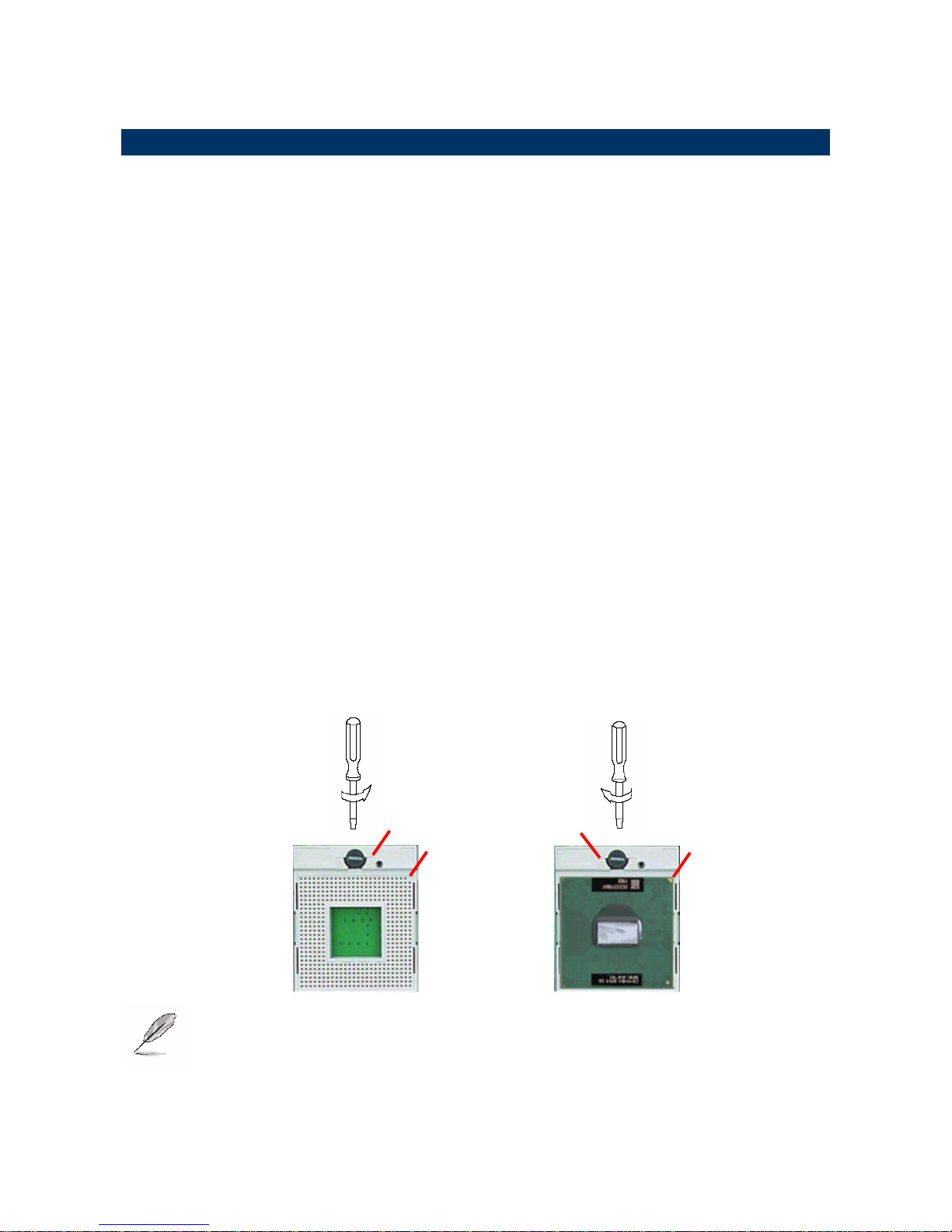
2.1.1 Processor Installation
2.1.1.1 Installing Pentium M CPU
• The processor socket comes with a screw to secure the processor, please unlock the
screw first.
• Position the CPU above the socket and the gold triangular mark on the CPU must
align with pin 1 of the CPU socket. Then Insert the CPU gently seated in place.
• Turn the screw to the lock position.
Note: Do not force the CPU into the socket. It may bend the pins and damage the
CPU.
Unlock
Pin 1 of the
socket
Gold
triangular
mark
Lock
User’s Manual
EMB-9670/9673 Series User’s Manual
27
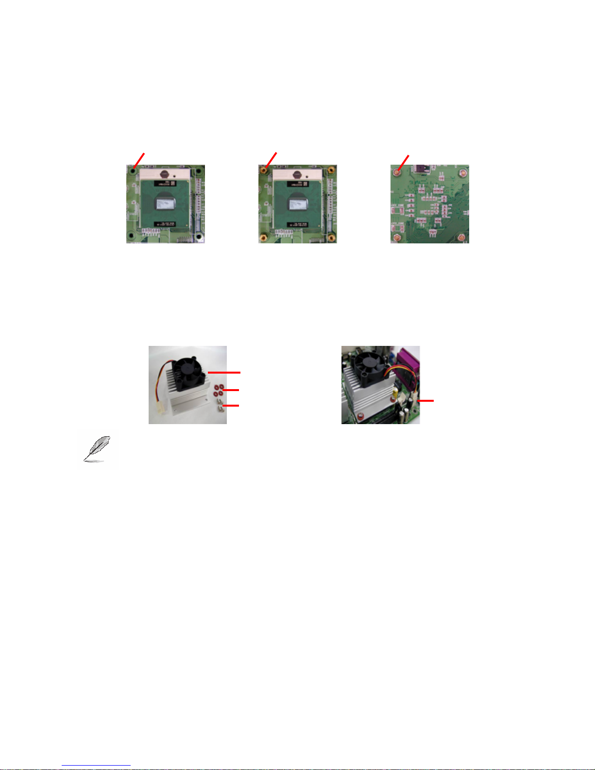
2.1.1.2 Installing the Fan and Heat Sink
• Insert the copper studs to the screw holes around the CPU socket from the top
through the rear side of the board with screw nuts fastened.
• Match and place the CPU fan and heat sink assembly on the top of the CPU and
copper studs. Tighten the screws into the copper studs through washers and the
screw holes around the heat sink.
• Place the CPU Fan Connector.
Note: Make sure the CPU fan and heat sink assembly and the CPU top surface
are in total contact to avoid CPU overheating problem that would cause the
system to hang or unstable
2.1.1.1 Removing CPU
• Disconnect the CPU fan connector.
• Remove the CPU fan and heat sink assembly first.
• Unfasten the copper studs from the board.
• Unlock the Pentium M processor.
• Carefully lift up the existing CPU to remove it from the socket.
• Follow the steps of installing a CPU to change to another one.
Copper Stud
Screw nut
(Rear side)
Screws
CPU Fan & heat
sink assembl
y
CPU fan
connector
EMB-9670/9673 Series
28 EMB-9670/9673 Series User’s Manual
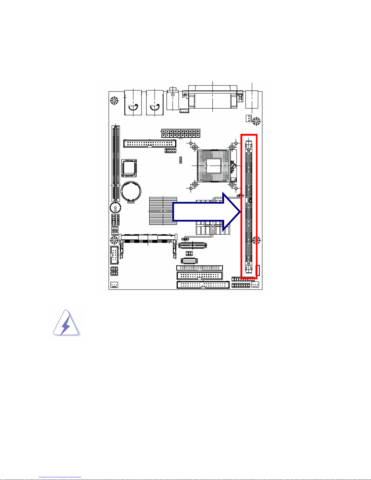
2.1.2 Main Memory
EMB-9670/9673 provides one 184-pin DIMM sockets to support DDR SDRAM. The total
maximum memory size is 1GB.
Make sure to unplug the power supply before adding or removing DIMMs or
other system components. Failure to do so may cause severe damage to
both the board and the components.
DIMM1
User’s Manual
EMB-9670/9673 Series User’s Manual
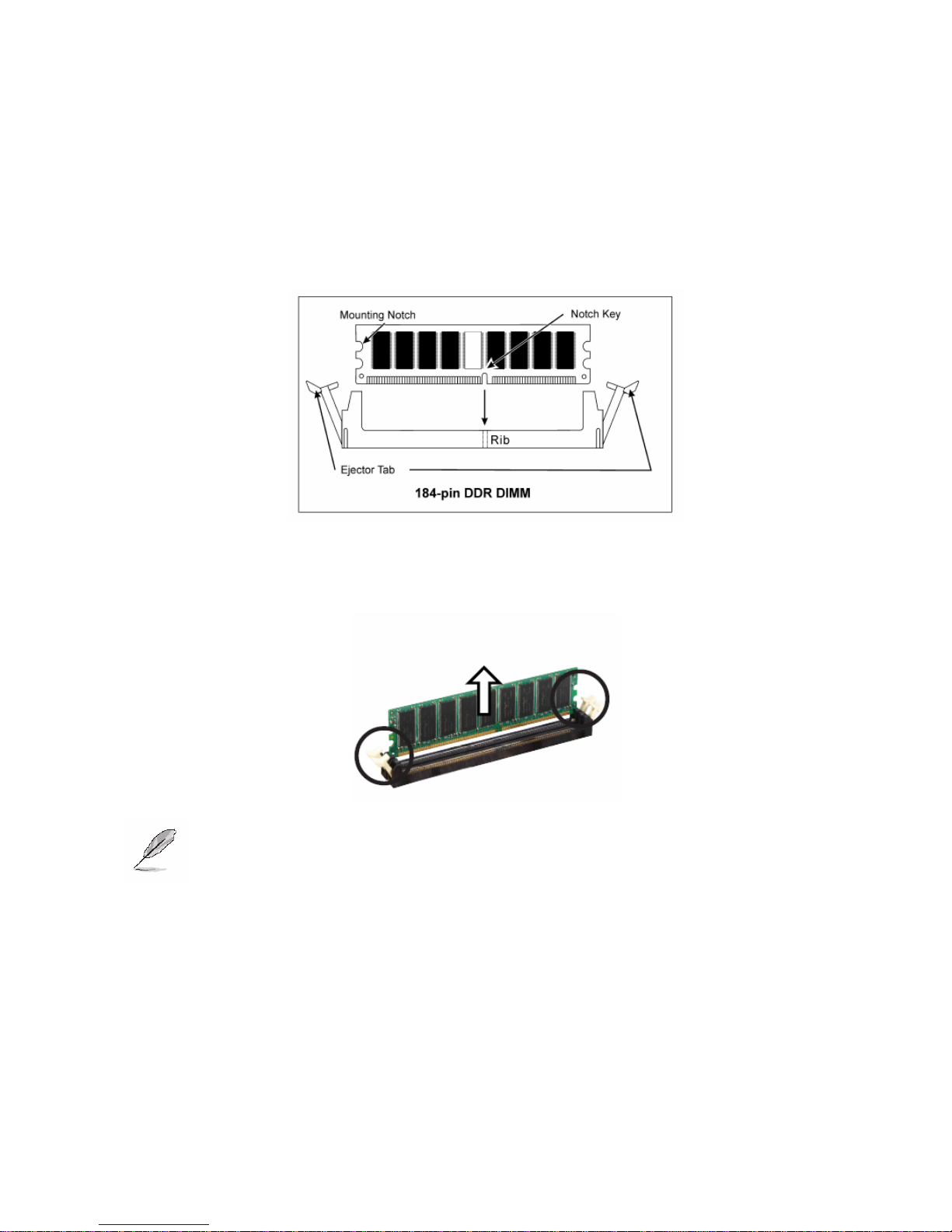
29
• Locate the DIMM slot on the board.
• Hold two edges of the DIMM module carefully. Keep away of touching its connectors.
• Align the notch key on the module with the rib on the slot.
• Firmly press the modules into the slot automatically snaps into the mounting notch. Do
not force the DIMM module in with extra force as the DIMM module only fit in one
direction.
• To remove the DIMM modules, push the two ejector tabs on the slot outward
simultaneously, and then pull out the DIMM module.
Note: (1) Please do not change any DDR SDRAM parameter in BIOS setup to
increase your system’s performance without acquiring technical
information in advance.
(2) Static electricity can damage the electronic components of the computer
or optional boards. Before starting these procedures, ensure that you
are discharged of static electricity by touching a grounded metal object
briefly.
EMB-9670/9673 Series
30 EMB-9670/9673 Series User’s Manual
2.2 Jumper and Connector List
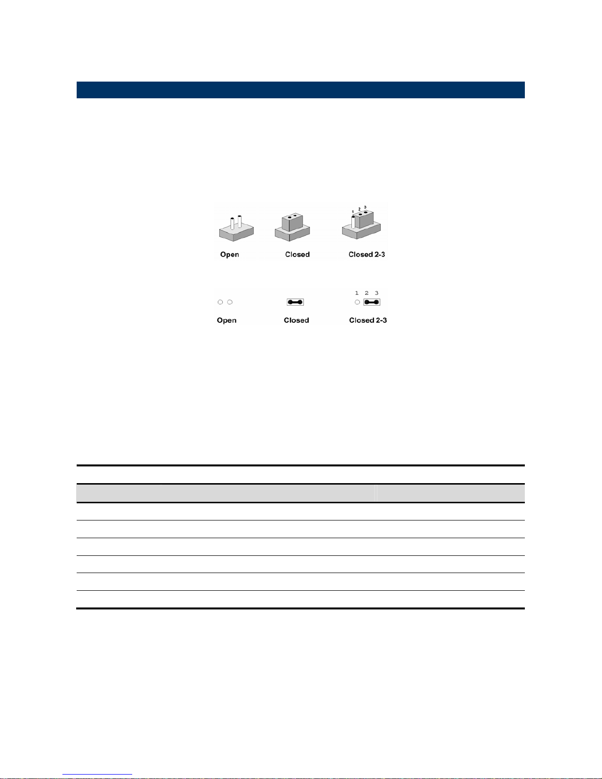
You can configure your board to match the needs of your application by setting jumpers. A
jumper is the simplest kind of electric switch.
It consists of two metal pins and a small metal clip (often protected by a plastic cover) that
slides over the pins to connect them. To “close” a jumper you connect the pins with the clip.
To “open” a jumper you remove the clip. Sometimes a jumper will have three pins, labeled 1,
2, and 3. In this case, you would connect either two pins.
The jumper settings are schematically depicted in this manual as follows:
A pair of needle-nose pliers may be helpful when working with jumpers.
Connectors on the board are linked to external devices such as hard disk drives, a
keyboard, or floppy drives. In addition, the board has a number of jumpers that allow you to
configure your system to suit your application.
If you have any doubts about the best hardware configuration for your application, contact
your local distributor or sales representative before you make any changes.
The following tables list the function of each of the board's jumpers and connectors.
Jumpers
Label Function Note
JBAT
Clear CMOS 3 x 1 header, pitch 2.54mm
JCPU1
Reserved
JP1
COM2 RS-232/422/485 select 3 x 2 header, pitch 2.54mm
JP2
COM2 pin 9 signal select 3 x 2 header, pitch 2.54mm
JP3
COM2 RS-232/422/485 select 4 x 3 header, pitch 2.54mm
SW1
FSB select DIP switch
 Loading...