

Vox Technologies EM586 User Manual

EM586
Embedded Single Board Computer
with full functionality, LCD/SVGA,
LAN, Sound output & PCI slot
This device complies with Part 15 of the FCC Rules
Operation is subject to the following two conditions:
1. This device may not cause harmful interference , and
2. This device must accept any interference received, Including
interference that may cause undesired operation.

COPYRIGHT©
This document is a copyright of the original manufacturer, 1999. The original
manufacturer reserves the right to make improvements to the product(s) described in
this manual at any time without notice. This manual may not, in whole or in part, be
photocopied, reproduced, transcribed, translated, or transmitted in whatever form
without the written consent of the manufacturer, except for copies retained by the
purchaser for backup purposes. All rights are reserved.
TRADEMARKS
Pentium® is a registered trademark of Intel Corporation.
The following are trademarks or registered trademarks of their respective companies:
IBM, Intel, AMD, Cyrix, Award, AMI, Microsoft, Windows, Windows NT, Novell, SCO,
PC/104, PICMG, ALI, UMC, SMC, Winbond. Products mentioned in this manual are
mentioned for identification purposes only. All names of products or services appearing
in this manual are the trademarks or registered trademarks of their respective
organizations and companies.
Copyright 1999
Ver. No. 1.2
LEI-UM-EM58600-002
Date : 10.27.1999

TABLE OF CONTENTS
CHAPTER 1 INTRODUCTION 1
1.1 SPECIFICATION 2
1.2 PACKING CHECK LIST 3
CHAPTER 2 JUMPER SETTINGS AND CONNECTORS 6
2.1 BOARD OUTLINE OF EM586 6
2.2 JUMPER SETTING OVERVIEW 7
2.3 INSTALLING THE SIM MODULE 7
2.4 JUMPER LOCATION FOR EM586 8
2.5 JUMPER SETTINGS SUMMARY FOR EM586 9
2.6 I/O CONNECTORS LOCATION FOR EM586 18
2.7 I/O CONNECTORS SUMMARY FOR EM586 19
2.8 I/O CONNECTORS DESCRIPTION 20
CHAPTER 3 AWARD BIOS SETUP 33
3.1 RUNNING AWARD BIOS 33
3.2 CMOS SETUP UTILITY 34
3.3 STANDARD CMOS SETUP 35
3.4 BIOS FEATURES SETUP 39
3.5 CHIPSET FEATURES SETUP 42
3.6 POWER MANAGEMENT SETUP 46
3.7 PNP/PCI CONFIGURATION 49
3.8 LOAD BIOS DEFAULTS 51
3.9 LOAD SETUP DEFAULTS 51
3.10 INTEGRATED PERIPHERALS 52
3.11 SUPERVISOR / USER PASSWORD 54
3.12 IDE HDD AUTO DETECTION 55
3.13 HDD LOW LEVEL FORMAT 55
3.14 SAVE & EXIT SETUP 55
3.15 EXIT WITHOUT SAVING 55

TABLE OF CONTENTS
CHAPTER 4 DRIVERS SUPPORT 56
4.1 DRIVERS DISKETTE LIST 56
4.2 TX DRIVER FOR WIN95 56
4.3 VGA DRIVER 59
4.4 TEMPERATURE ALARM DRIVER 64
4.5 LAN DRIVER 70
4.6 SOUND DRIVER 77
APPENDIX A HOW TO USE WATCH-DOG TIMER 83
APPENDIX B TECHNICAL REFERENCE 84
APPENDIX C PC/104 MODULE INSTALLATION 86
GLOSSARY 87
TERMS AND CONDITIONS
RMA SERVICE REQUEST FORM

EM586 / 1
INTRODUCTION
The EM586 is an embedded single board computer with full functionality, LCD/SVGA,
LAN, Sound output & a PCI slot for Intel 430TX Processor. It consists of an on-board
SVGA & Audio output, a PCI Ethernet Interface and a PCI expansion slot (PCI). The
Intel 430TX establishes a new class of low-cost, high-performance system that offers all
the functions of an industrial computer on a single board, and fits in the space of a 5.25inch floppy drive (only 5.75” x8” ). The EM586 has an on-board 2nd level cache RAM of
512KB for maximum performance. This design eliminates system conflicts and enduser configuration problems.
For the embedded board market this means more memory, more processing might, and
more I/O can be packed tighter. The form factor dispenses with the complexity, cost,
and bulk of conventional motherboards, backplanes, and card cages. The embedded
single board computer in EM586 also comes with the most popular PC/104 self –
stacking bus connector that suits the small form-factor board standards (compact
PC/104 3.6 x 3.8-inch self-stacking, modular format.). Today, the basic PC architecture
is used in such diverse embedded applications as vending machines, communications
devices, portable systems, and medical equipment. Among PC/104 standardizes the
repackaging of desktop PC functions to satisfy the ruggedness, reliability, and size
constraints of embedded systems. PC/104 lets you combine special-purpose
embedded functions with the basic PC computing core.
Other on-board features include four serial ports (RS-232 and RS-232/422/485), one
multi-mode parallel (ECP/EPP/SPP) port, a floppy drive controller and a keyboard
interface and a PS/2 mouse interface. The built-in high speed PCI IDE controller
supports both PIO and bus master modes. Up to two IDE devices can be connected,
including large hard disks, CD-ROM drives, tape backup drives and other IDE devices.
Its 6-layer printed circuit board combines with noise-tolerant and low power consumption
CMOS technology applied on the board makes EM586 able to withstand any harsh
industrial environments very well.
CHAPTER 1.

INTRODUCTION
EM586 / 2
1.1 S
PECIFICATIONS
o Processor : Intel Pentium® P54C/P55C, AMD K5/K6, Cyrix 6x86
series processor
o Chipset : Intel 430TX chipsets, CHIPS 65555, Genesys 518SM,
Realtek 8139, ESS 1869 sound chip, Winbond 977TF
& 877TF I/O compatible chips
o System Memory : Two 72-pin SIMM sockets that support up 128MB of
FPM/EDO DRAM
o Cache Memory : 512KB pipelined burst synchronous cache
o BIOS : 256KB Licensed Award & AMI Flash BIOS
o Flash Memory Disk : Reserved socket for DiskOnChip from M-System,
support up to 72 MB flash memory Disk
o VGA/LCD Controller : C&T 65555 LCD/CRT chipset on-board 2MB video
memory, resolution up to 1280 x 1024 x 16bpp
o Ethernet Controller : On-board Realtek 8139, support 100 BASE-TX
o Sound Output : On-board ESS 1869 ISA interface
o IDE Drive Interface : One PCI IDE port, support up to two IDE devices and
Ultra DMA/33
o Floppy Drive Interface : One FDD port, support up to two floppy devices
o Serial Port : Four COM ports for three RS-232 and one selectable
RS-232/422/485
o Parallel Port : One multi-mode parallel port (EPP/ECP/SPP)
o RTC Battery : Dallas RTC battery or compatible
o DMA : 8 DMA channels
o Interrupts : 16 levels of hardware interrupts
o External Power Connector : On-board 4-pin & 5-pin external power connector
o PC/104 Expansion Bus : Built-in PC/104 expansion bus
o Expansion Slot : Built-in one PCI expansion slot
o Watchdog Timer : 7 level time-out intervals (0.5/1/2/4/16/32/64 sec.)
o Digital I/O : 4 bit Digital input / 4 bit Digital output
o Universal Serial Bus : Support two USB ports
o IR Interface : Supports one IrDA header
o Health Monitoring : On-board Genesys 518SM, support CPU temperature
alarm
o Operating Temperature : 0°C~55°C (32°F~132°F)
o Humidity : 10¢H~90¢H RH
o Dimensions : 203 mm X 146 mm (8” X 53/4” inches)
o Net weight : 350 g (0.770 pounds)
INTRODUCTION
EM586 / 3
1.2 PACKING CHECK LIST
Before you begin to install your card, please make sure that you received the following
materials as listed below:
l Standard Packing
¡G
Item Qty Remark
ŒEM586 Embedded Single Board Computer 1 pc. EM586 SBC
•Flat-Panel/SVGA/Utility/LAN Drivers 5 pcs. Drivers diskette
ŽUser‘ s manual 1 pc. EM586 manual
Note¡GAll Option Kits are to be purchased separately
l Option (1)¡G EM586CB
Item Qty Remark
ŒEIDE cable 1 pc. 44-pin narrow header to 40-pin standard header
•Floppy cable 1 pc. 34-pin standard header to 34-pin etch connector
ŽPrinter port cable 1 pc. 26-pin standard header to 25-pin female D-Sub
(Attached to standard I/O card bracket)
•CRT-2 cable 1 pc. 12-pin standard header to 15-pin/3-rows D-Sub
•Game port cable 1 pc. 16-pin standard header to 15-pin/2-rows D-Sub
‘PC/104 Mounting kit 1 set
4¡Ñbrass spacer (25mm)
4¡Ñnull
4¡Ñscrews (M3¡Ñ6)
INTRODUCTION
EM586 / 4
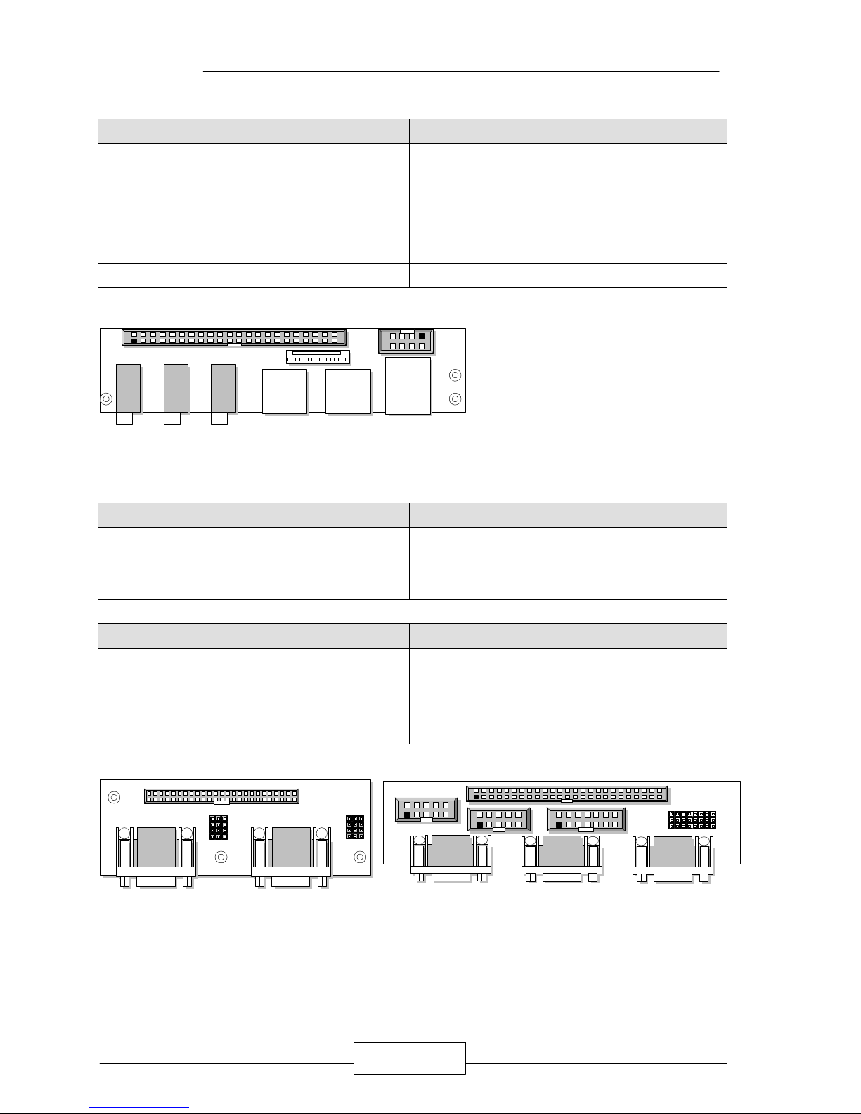
l Option (2)¡G EMUKMS-02 kit
Item Qty Remark
ŒEMUKMS-02
(USB/Keyboard/Mouse/Sound cabled kit )
1 set
1¡Ñ 44-pin to 44-pin thin flat ribbon female cable
1¡Ñ U-K-M-S board 92.92¡Ñ27.00 mm
(with 3¡ÑSound phone jack, 1¡Ñ6-pin PS/2
Keyboard connector, 1¡Ñ6-pin PS/2 Mouse
and 1x USB connector)
•Keyboard adapter cable 1 set 6-pin header to 5-pin PS/2 keyboard connector
l Option (3)¡G EMCOM-01 or EMCOM-02 kit
Item Qty Remark
ŒEMCOM-01
(COM cabled kit )
1 set
1¡Ñ 50-pin to 44-pin thin flat ribbon female cable
1¡Ñ Four COM port board 90.00¡Ñ30.00 mm
(with 4¡Ñ9-pin COM port female D-sub connector)
Item Qty Remark
ŒEMCOM-02
(COM cabled kit )
1 set
1¡Ñ 50-pin to 50-pin thin flat ribbon female cable
1¡Ñ Four COM port board 111.58¡Ñ30.00 mm
(with 3¡Ñ9-pin COM port female D-sub connector,
and 1X10-pin COM port standard header)
2
1
COM1
JP1 ~~ JP8
EMCOM-02
2
1
2
1
2
1
14
13
50
49
2
1
3
CN2
CN3
CN1
EMCOM-02 Kit Top View ¡G
COM2
2 44
CN1
431
COM4
1 2 21
CM1 CM2
JP8
JP7
JP6
JP5
JP4
JP3
JP2
JP1
3 3
EMCOM-01 Kit Top View ¡G
2 44
431
USB2
KBMS1
UKMS1
EMUKMS-02 Kit Top View ¡G
INTRODUCTION
EM586 / 5
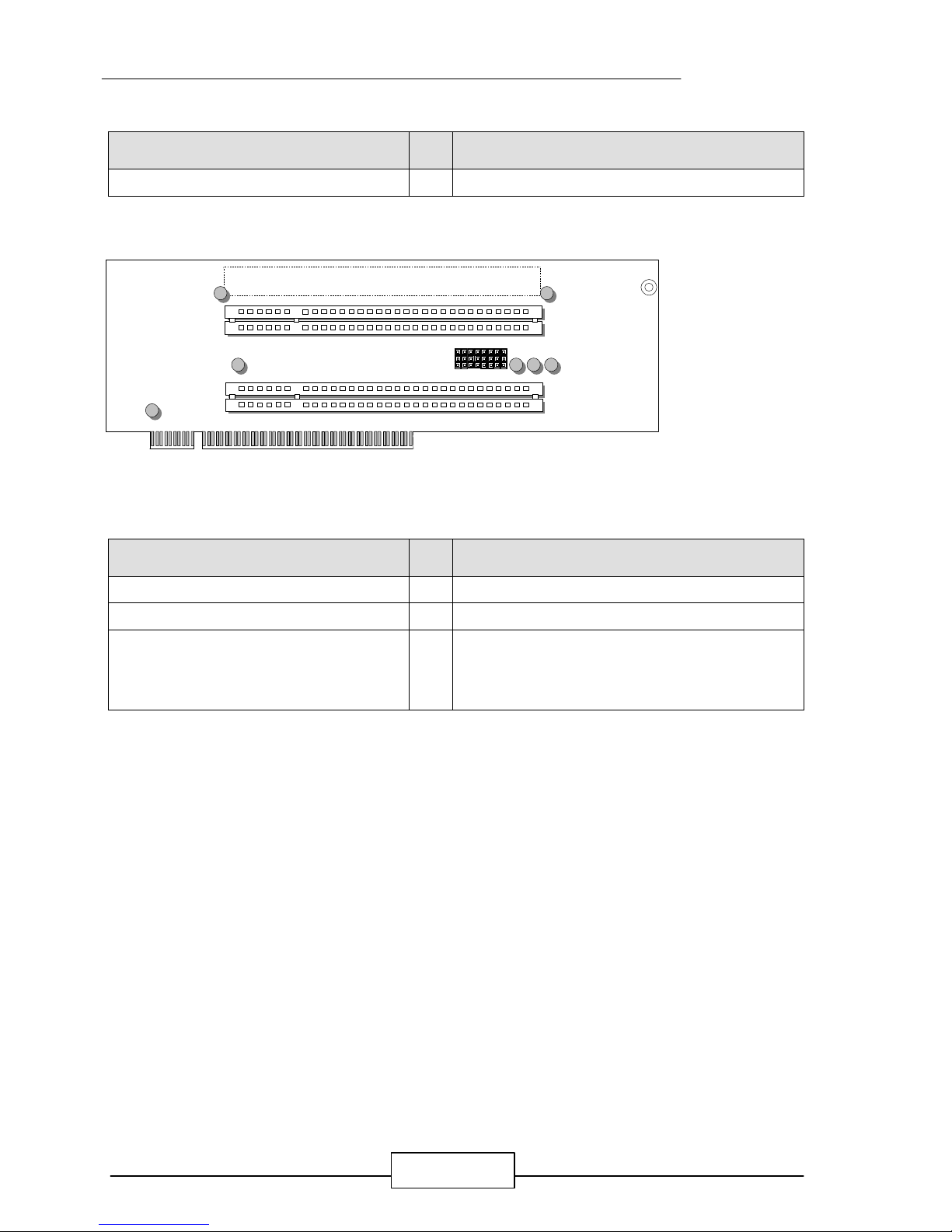
l Option (4)¡G EMRISER-03 Riser Card Kit
¡G
Item Qty Remark
ŒEMRISER-03 1 pc.
2¡Ñ PCI Slots Riser Card 147.78¡Ñ63.10 mm
l Option (5)¡G LCD Adapter Kit¡G[ for example
¡G
LK-XXX (XXX=001,002,……)]
Item Qty Remark
ŒLCD Adapter 1 pc. Please check LCD adapter list user’ s manual
•LCD adapter list user’ s manual 1 pc. LCD adapter list manual
ŽLCD/Flat-Panel adapter cable
(An Option Kit, please check your
requirement with the LCD Adapter List)
1 set Please check LCD adapter list user’ s manual
EMRISER-03 Riser Card Top View ¡GJumper Setting : JP1 ~ JP8 Manufacturer Setting on 1-2
PCI3
PCI2
JP1 ~ ~JP8
3
2
1
EM586 / 6
JUMPER SETTINGS AND CONNECTORS
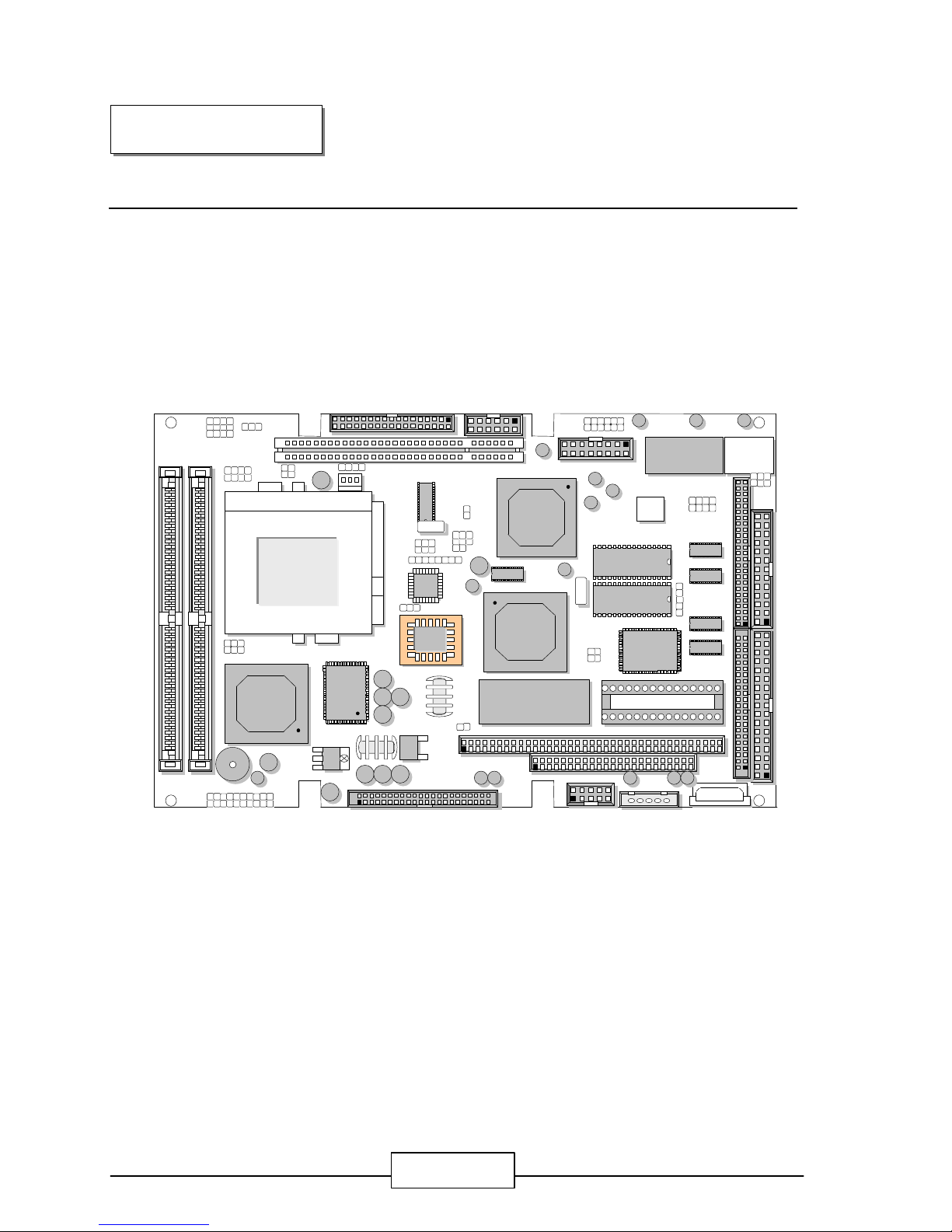
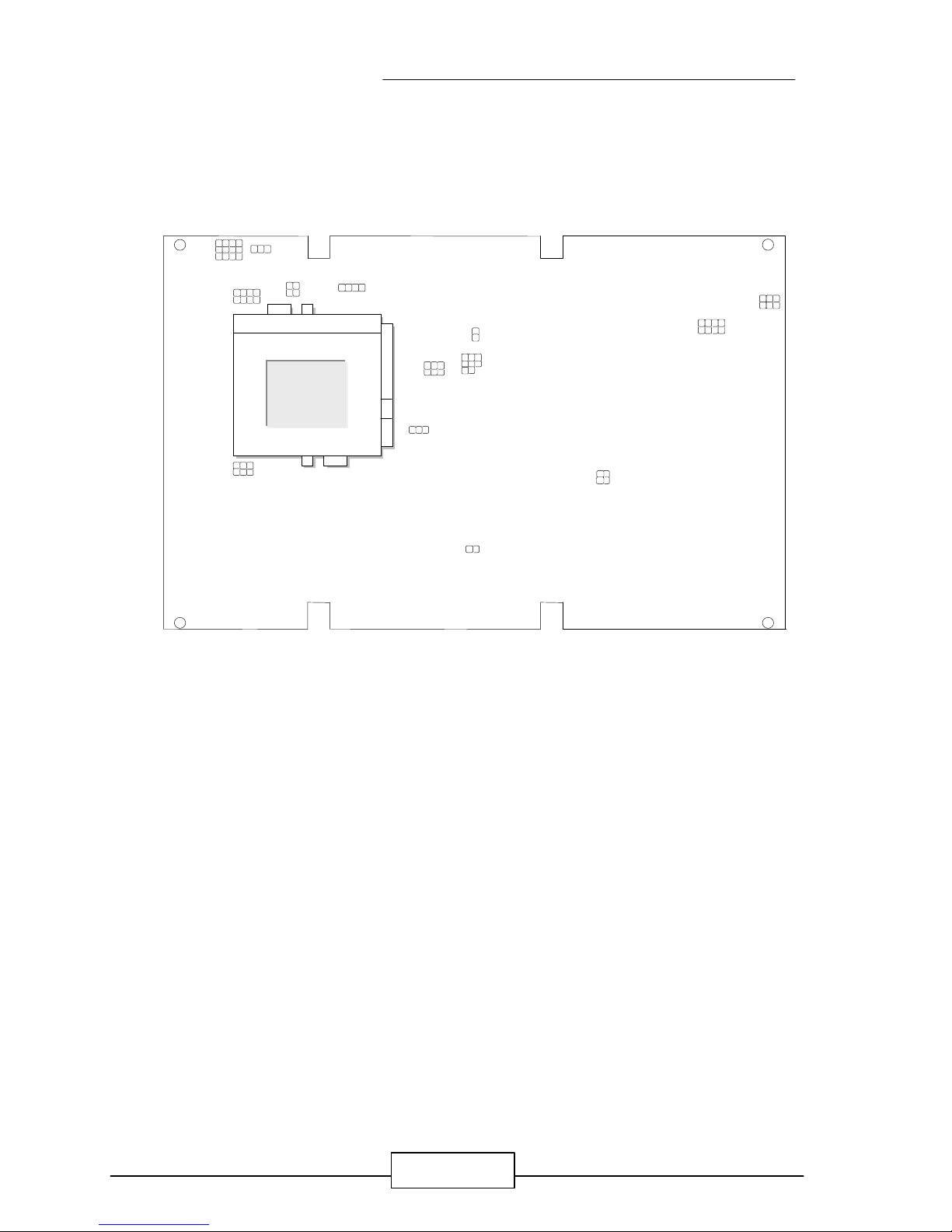
The Figure below shows the jumpers and connectors location on the EM586:
2.1 BOARD OUTLINE OF EM586
CHAPTER 2.
1
3
2
JP3
11H
7 2 3 4L
8
JP6
SIMM1
SIMM2
DIO1
PS1
PS2
FDC1
LPT1
15 2
6
JP7
1
712
6
J1
GAM1
J2
1
287
IR1
JP21
S1
CON1
CON2
ABCD1
1
JP17
JP19
JP18
1 1 2 5 6
3
Intel
82439TX
Intel
82371EB
CHIPS
B65555
J4
111 10
20
LAN1
CN2
12 43
44
CN1
EIDE1
S3
Realtek
RTC
¹
JP31
JP30
1
2
JUMPER SETTING AND CONNECTORS
EM586 / 7
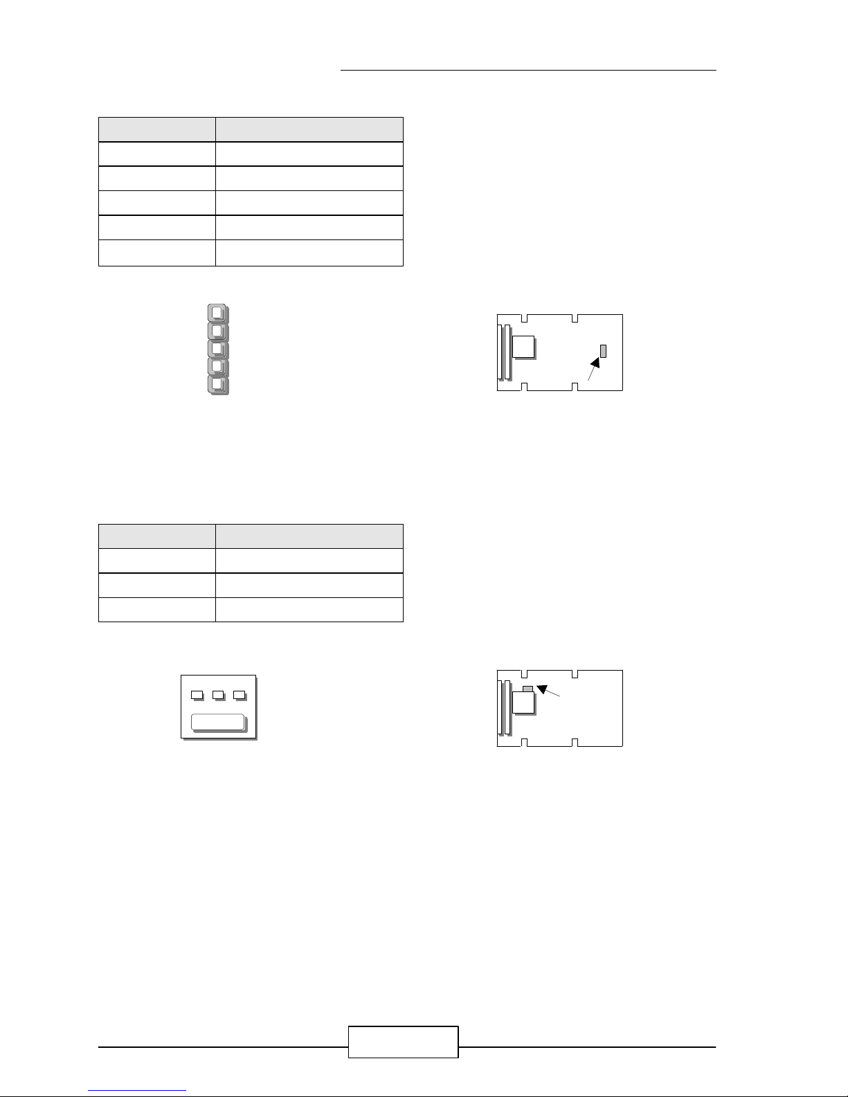
2.2JUMPER SETTING OVERVIEW
In order to select the operation modes of your system, configure and set the jumpers on
the your Embedded SBC to match the need of your application. To set a jumper, a
black plastic cap containing metal contacts is placed over the jumper pins as designated
by the required configuration as listed in this section. A jumper is said to be “ on ” or
“ 1-2 ” when the black cap has been placed on two of its pins, as show in the figure
below:
A pair of needle-nose pliers is recommended when working with jumpers. If you have
any doubts about the best hardware configuration for your application, contact your local
sales representative before you make any changes. In general, you simply need a
standard cable to make most connections.
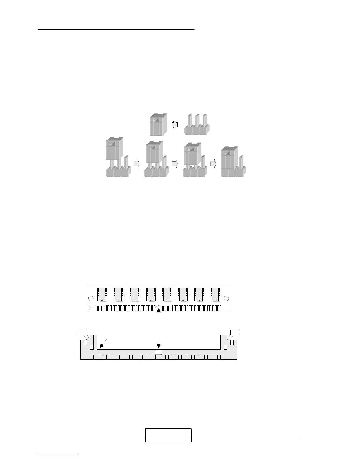
2.3 INSTALLING THE SIM MODULE:
A SIM module simply snaps into a socket on the system board. Pin1 of the SIM module
must correspond with Pin1 of the socket.
1. Position the SIMM above the socket with the “notch” in the module aligned with the
“key” on the socket.
2. Seat the module at a 45 angle into the bank. Make sure it is completely seated. Tilt
the module upright until it locks in place in the socket.
Pin1
Notch
Key
JUMPER SETTING AND CONNECTORS
EM586 / 8
2.4 JUMPER LOCATION FOR EM586
2
JP3
8
1
2 5 6
2
6
JP7
J2
1
2
JP21
S1
J3
1
3
JP17
JP19
JP18
JP20
1 1 2 5 6 31
3
JP30 JP31
JP34
JP35

JUMPER SETTING AND CONNECTORS
EM586 / 9
2.5 JUMPER SETTINGS SUMMARY FOR EM586
JUMPERS
LOCATION FUNCTION
JP3 Select Panel Voltage
JP4 Select Watch-Dog Time Out Period
JP6 Select Vore Voltage
JP7 Select COM4 Type
EMCOM-01
JP5~JP8
EMCOM-02
JP1~JP8
Select COM4 Type
(EMCOM-01 JP1~JP4 Manufacturer Setting )
Select COM4 Type
(EMCOM-02 JP1~JP8 Manufacturer Setting )
JP17 Manufacturer Setting
JP18 Select CPU External BUS Clock
JP19 Manufacturer Setting
JP20 Select Software Watch-Dog or Hardware Watch-Dog
JP21 Select Disk On Chip (Flash Disk) Address
JP22 Select Internal CPU Clock Ratio
JP30 ~ JP35 Select PCI Slot1 Type
J2 Select Panel Type
J3 Select Watch-Dog Active Type
S1 Clear CMOS Jumper
S3 Select onboard VGA or VGA Card
JUMPER SETTING AND CONNECTORS
EM586 / 10
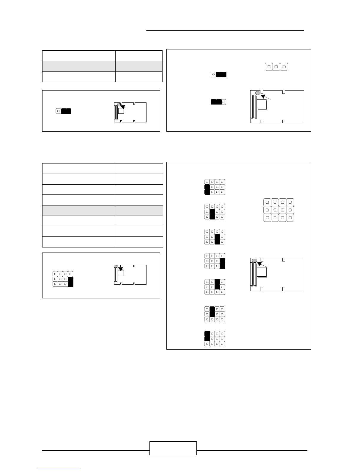
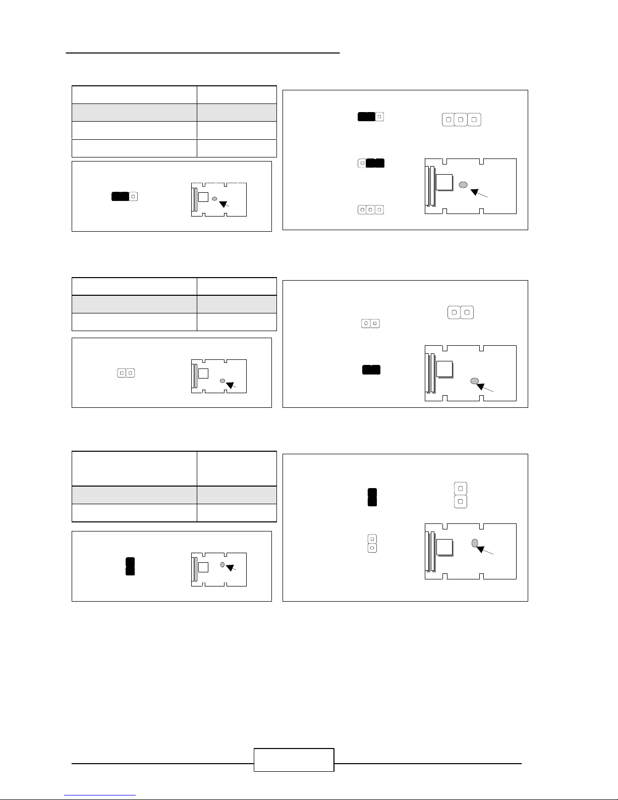
l JP3 : Select Panel Voltage
Panel Voltage JP3
3V ( Default ) 1-2
5V 2-3
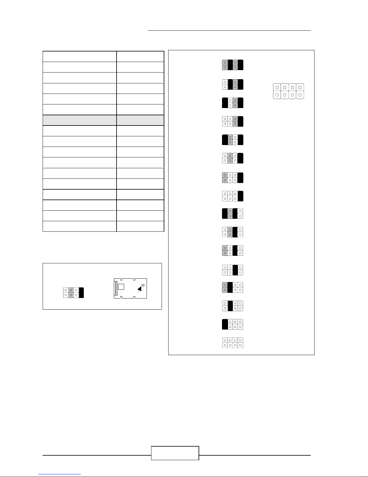
l JP4 : Select Watch-Dog Time Out Period
Time Out Period JP4
0.5 sec 1-5
1 sec 2-6
2 sec 3-7
4 sec ( Default ) 4-8
16 sec 7-11
32 sec 6-10
64 sec 5-9
JP3
5V
3V
3 2 1
JP3
3 2 1
JP3
Default :
JP3
3 2 1
Default :
JP4
9 10 11 12
1 2 3 4
1
JP4
0.5 SEC
1 SEC
2 SEC
4 SEC
16 SEC
32 SEC
64 SEC
234
9 10 11 12
JP4
JP4
1 2 3 4
9 10 11 12
3.
JUMPER SETTING AND CONNECTORS
EM586 / 11
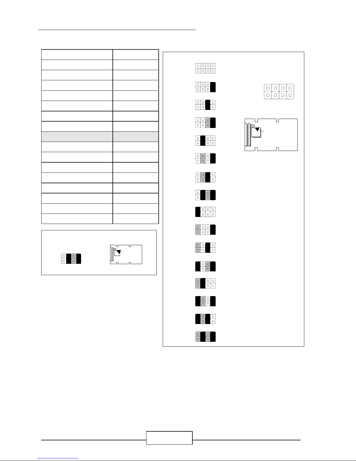
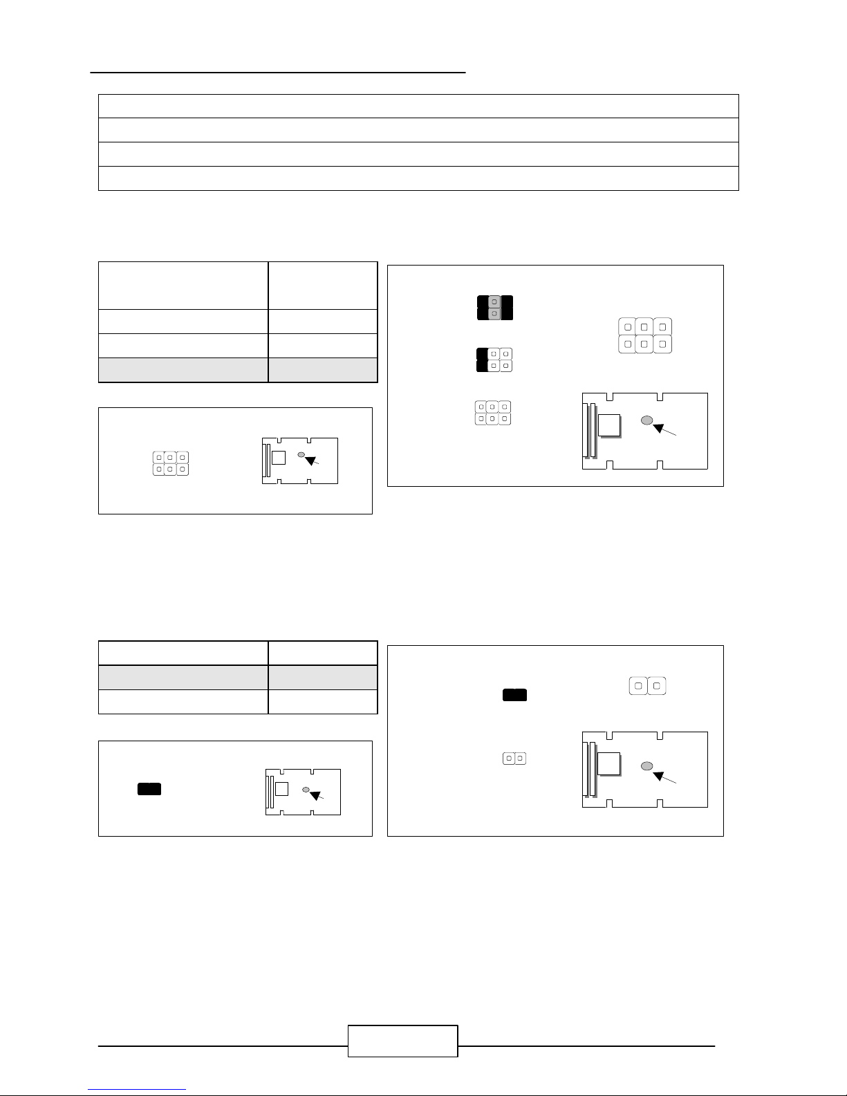
l JP6 : Select Vcore Voltage
Vcore Voltage JP6
3.5 V OFF
3.4 V 1-2
3.3 V 3-4
3.2 V 1-2,3-4
3.1 V 5-6
3.0 V 1-2,5-6
2.9 V 3-4,5-6
2.8 V( Default ) 1-2,3-4,5-6
2.7 V 7-8
2.6 V 1-2,7-8
2.5 V 3-4,7-8
2.4 V 1-2,3-4,7-8
2.3 V 5-6,7-8
2.2 V 1-2,5-6,7-8
2.1 V 3-4,5-6,7-8
2.0 V 1-2,3-4,5-6,7-8
JP6
7 5 3 1
JP6
8 6 4 2
3.5 V
3.4 V
3.3 V
3.2 V
3.1 V
3.0 V
2.9 V
2.8 V
2.7 V
2.6 V
2.5 V
7 5 3 1
8 6 4 2
2.4 V
2.3 V
2.2 V
2.1 V
2.0 V
JP6
Default :
7 5 3 1
JP6
8 6 4 2
JUMPER SETTING AND CONNECTORS
EM586 / 12
l JP7 : Select COM4 Type
COM4 Type JP7
RS-485 1-2
RS-422 3-4
RS-232 ( Default ) 5-6
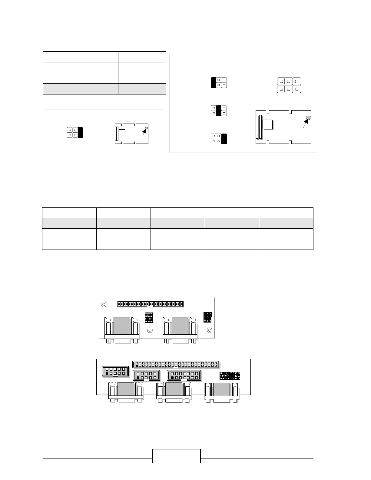
l EMCOM-01 Jumper Setting
¡G
1. JP1~JP4¡GManufacturer Setting
2. JP5~JP8¡GSelect COM4 Type
COM4 Type JP5 JP6 JP7 JP8
RS-232 (Default) 1-2 1-2 1-2 1-2
RS-422 2-3 2-3 2-3 2-3
RS-485 2-3 2-3 2-3 2-3
l EMCOM-02 Jumper Setting
¡G
1. JP1~JP8¡GManufacturer Setting
Default :
1
JP7
2
3 5
4 6
JP7
RS-422
RS-232
RS-485
2 4 6
1 3 5
6
JP7
1 3 5
42
JP7
2
1
COM1
JP1 ~~ JP8
EMCOM-02
2
1
2
1
2
1
14
13
50
49
2
1
3
CN2
CN3
CN1
EMCOM-02 Kit Top View ¡G
2 44
CN1
431
1 2 21
CM1 CM2
JP8
JP7
JP6
JP5
JP4
JP3
JP2
JP1
3 3
EMCOM-01 Kit Top View ¡G
JUMPER SETTING AND CONNECTORS
EM586 / 13
CPU Speed Reference Table
CPU Speed (MHz) 75 90 100 120 133 150 166 200 233
Clock setting 50 60 66.6 60 66.6 60 66.6 66.6 66.6
Frequency ratio 1.5 1.5 1.5 2 2 2.5 2.5 3 3.5
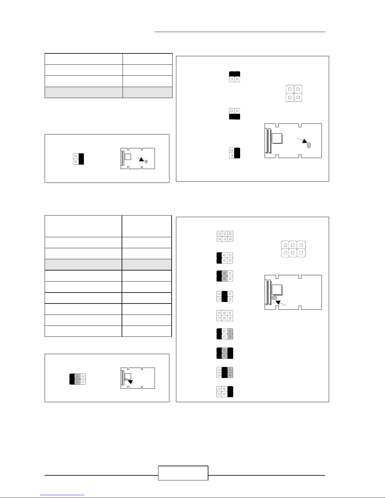
l JP18 : Select CPU External Bus Clock
CPU External Bus
Clock
JP18
50 MHz 1-2,3-4,5-6
60 MHz 1-2
66.6 MHz (Default ) OFF
l JP20 : Select Software Watch-Dog or Hardware Watch-Dog
Panel Voltage JP20
Hardware ( Default ) ON
Software OFF
Default :
2
1
JP18
6
5
Default :
JP20
1 2
JP18
2
6
2
JP18
50MHz
60MHz
66.6MHz
165
JP18
3.0 X
Software
Hardware
1 2
JP20
1 2
JP20
JP20
JUMPER SETTING AND CONNECTORS
EM586 / 14
l JP21 : Select Disk On Chip ( Flash Disk ) Address
lash Disk Address JP21
D0000~D7FFF 1-2
D8000~DFFFF 3-4
Default 2-4
l JP22 : Select Internal CPU Clock Ratio
Internal CPU Clock
Ratio
JP22
1.5 X OFF
2.0 X 1-2
2.5 X (Default ) 1-2,3-4
3.0 X 3-4
3.5 X OFF
4.0 X 1-2,5-6
4.5 X 1-2,3-4,5-6
5.0 X 3-4,5-6
5.5 X 5-6
Default :
2
1
JP22
6
5
JP21
D0000~D7FFF
D8000~DFFFF
JP21
2
4
1
3
JP21
1
3 4
2
Default
Default :
1
3
JP21
2
4
JP22
2
6
2
JP22
1.5 X
2.0 X
2.5 X
3.5 X
165
JP22
4.0 X
4.5 X
5.0 X
5.5 X
3.0 X
JUMPER SETTING AND CONNECTORS
EM586 / 15
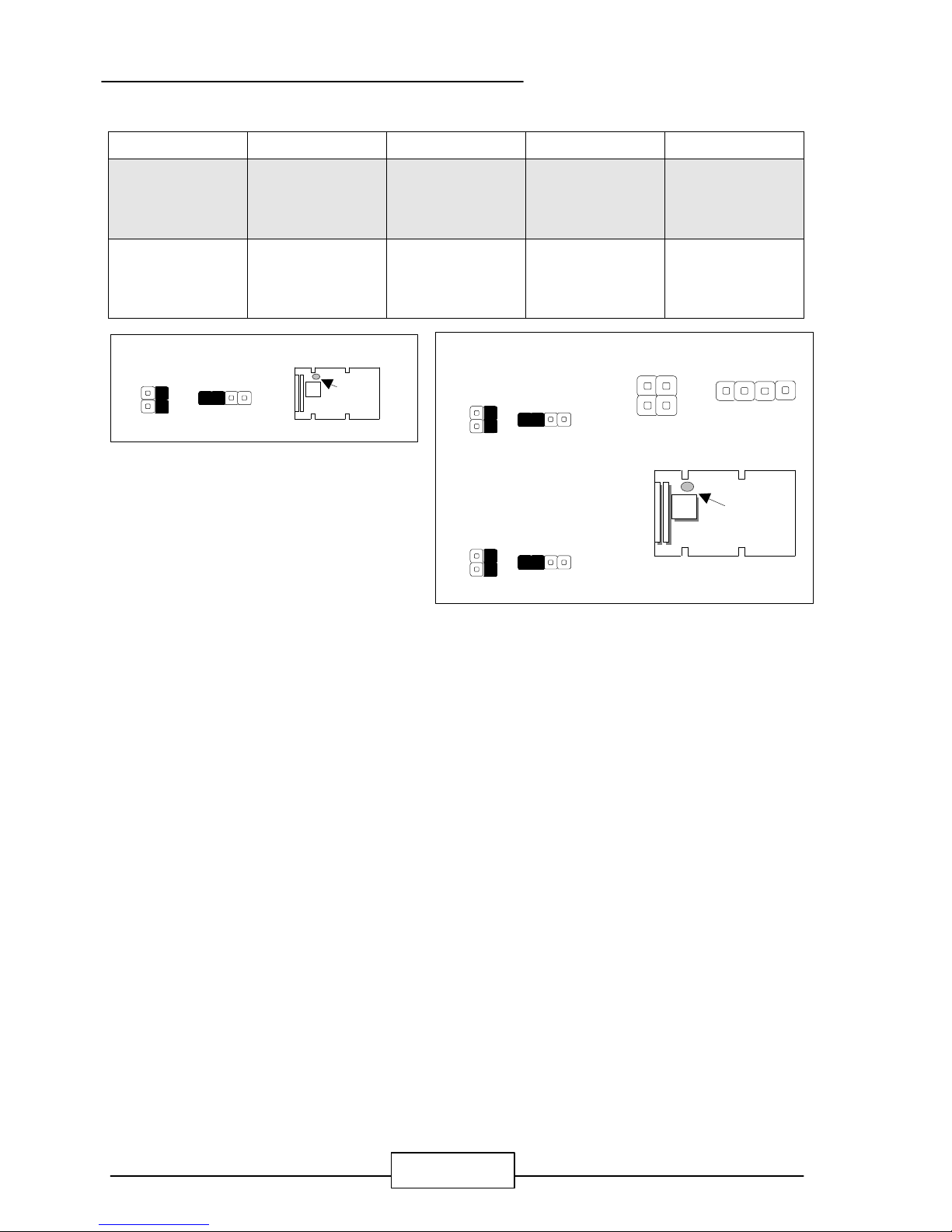
l J3 : Select PCI Slot1 Type
PCI Slot1 Type JP30 JP31 JP34 JP35
On Board
PCI Slot
(Default)
OFF ON ON OFF
Use
EMRISER-03
Slot Board
ON OFF OFF ON
Default :
JP34
1 2 1 2
JP35
JP30
1
2
1
2
JP31
JP31 ~ JP35
Use EMRISER-03 Slot
Board
On Board PCI Slot
JP34
1 2 1 2
JP35
JP30
1
2
1
2
JP31
JP34
1 2 1 22
11
2
JP35
JP32JP31
JP34
1 2 1 2
JP35
JP30
1
2
1
2
JP31
JUMPER SETTING AND CONNECTORS
EM586 / 16
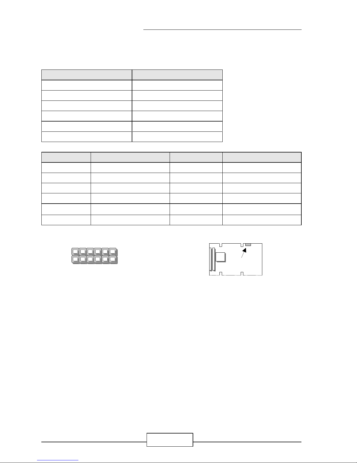
l J2 : Select Panel Type
Panel Type J2
1024 X 768 DSTN 1-2,3-4,5-6,7-8
1280 X 1024 TFT 1-2,3-4,5-6
640 X 480 DSTN 1-2,3-4,7-8
800 X 600 DSTN 1-2,3-4
640 X 480 Sharp TFT 1-2,5-6,7-8
640 X 480 18Bits TFT 1-2,5-6
1024 X 768 TFT 1-2,7-8
800 X 600 TFT 1-2
800 X 600 TFT 3-4,5-6,7-8
800 X 600TFT 3-4,5-6
800 X 600 DSTN 3-4,7-8
800 X 600 DSTN 3-4
1024 X 768 TFT 5-6,7-8
1280 X 1024 DSTN 5-6
1024 X 600 DSTN 7-8
1024 X 600 TFT OFF
Note: Different type of LCD panel with the same
resolution will have different jumper
setting for selection.
7 5 3 1
J2
8 6 4 2
1024X768 DSTN
1280X1024 TFT
640X480 DSTN
800X600 DSTN
640X480 Sharp TFT
640X480 18Bits TFT
1024X768 TFT
800X600 TFT
800X600 TFT
800X600 TFT
800X600 DSTN
800X600DSTN
1024X768TFT
1280X1024 DSTN
1024X600 DSTN
1024X600 TFT
7 5 3 1
8 6 4 2
J2
Default :
7 5 3 1
J2
8 6 4 2
JUMPER SETTING AND CONNECTORS
EM586 / 17
l J3 : Select Watch-Dog Active Type
Active Type J3
Reset System (Default) 1-2
NMI System 2-3
Disable OFF
l S1 : Clear CMOS Jumper
Clear CMOS Jumper S1
Normal ( Default ) OFF
Clear CMOS 1-2
l S3 : Select onboard VGA or VGA Card
Onboard VGA or VGA
Card
S3
Onboard VGA (Default) 1-2
VGA Card OFF
l JP17 : Default Setting ( 1-2 )
l JP19 : Default Setting ( 1-2 )
Note : Do not attempt to change the default setting of JP17 and JP19 unless the
manufacturer would like to change the specification.
S3
VGA Card
Onboard VGA
1
2
S3
1
2
S3
Default :
S3
1
2
J3
J3
1 2 3
J3
NMI System
Reset System
1 2 3
Disable
S1
Clear CMOS
2 1
S1
2 1
S1
Default :
J3
1 2 3
Default :
S1
2 1

JUMPER SETTING AND CONNECTORS
EM586 / 18
2.6 I/O CONNECTOR LOCATION FOR EM586
1
712
6
J1
GAM1
VGA1
LCD1
IR1
CON1
ABC
1
1
J4
LAN1
CN1
EIDE1

JUMPER SETTING AND CONNECTORS
EM586 / 19
2.7 I/O CONNECTOR SUMMARY OF EM586
CONNECTORS
LOCATION FUNCTION
J1 LAN LED & Sound Switch
J4 System Switch and LED
IR1 Alternate IrDA
FAN1 FAN Connector
PS1 5-Pin Power Connector
PS2 4-Pin Power Connector
CN1 COM1~COM4 Connector ( Header )
CN2
CD_IN, MIC_IN, LIN_IN, Mouse, Keyboard, USB1, USB2 Connector
LCD1 Panel LCD Connector ( Header )
FDC1 Floppy Interface Connector ( Header )
LPT1 Parallel Port Connector ( Header )
EIDE1 EIDE Interface Connector ( Header )
VGA1 External VGA Connector ( Header )
LAN1 LAN Connector ( Header )
DIO1 Digital Input / Digital Output Ports ( Header )
GAM1 GAME Port Connector ( Header )
CON 1¡BCON2
PC104 Connector
JUMPER SETTING AND CONNECTORS
EM586 / 20
2.8 I/O CONNECTORS DESCRIPTION
l J1 : LAN LED & Sound Switch
J1 Connector Description
Pin 1 & Pin 7 of J1 10M LED
Pin 2 & Pin 8 of J1 RX-TX ACT LED
Pin 3 & Pin 9 of J1 100M LED
Pin 4 & Pin 10 of J1 MUTE SW
Pin 5 & Pin 11 of J1 VOL+ SW
Pin 6 & Pin 12 of J1 VOL- SW
J1 Pin No. Signal J1 Pin No. Signal
1 10M 7 VCC
2 RX-TX 8 VCC
3 100M 9 VCC
4 Ground 10 MUTE
5 Ground 11 VOL+
6 Ground 12 VOL-
J1
J1
7
16
12
JUMPER SETTING AND CONNECTORS
EM586 / 21
l J4 : System Switch and LED
J4 Connector Description
Pin 1 ~ Pin 3 of J4 Power LED
Pin 4 ~ Pin 5 of J4 Key Lock
Pin 7 ~ Pin 10 of J4 Speaker
Pin 11 ~ Pin 12 of J4 Reset SW
Pin 15 ~ Pin 16 of J4 Green SW
Pin 19 ~ Pin 20 of J4 HDD LED
J4 Pin No. Switch and LED J4 Pin No. Switch and LED
1 Power LED+ 11 Reset SW1
2 Power LED- 12 Reset SW2
3 Power LED- 13 NC
4 Keylock 1 14 NC
5 Keylock 2 15 Green SW1
6 NC 16 Green SW1
7 Speaker+ 17 VCC
8 Ground 18 NC
9 NC 19 HDD LED+
10 Speaker Signal 20 HDD LED-
J4
J4
10
2011
1
JUMPER SETTING AND CONNECTORS
EM586 / 22
l IR1 : Alternate IrDa
Pin No. Description
1 VCC
2 FIRRX
3 IRRX
4 GND
5 IRTX
l FAN1 : FAN Connector
Pin No. Description
1 Ground
2 +12V
3 FAN Status
IR1
IR1
1
2
3
4
5
FAN1
FAN1
1 2 3
JUMPER SETTING AND CONNECTORS
EM586 / 23
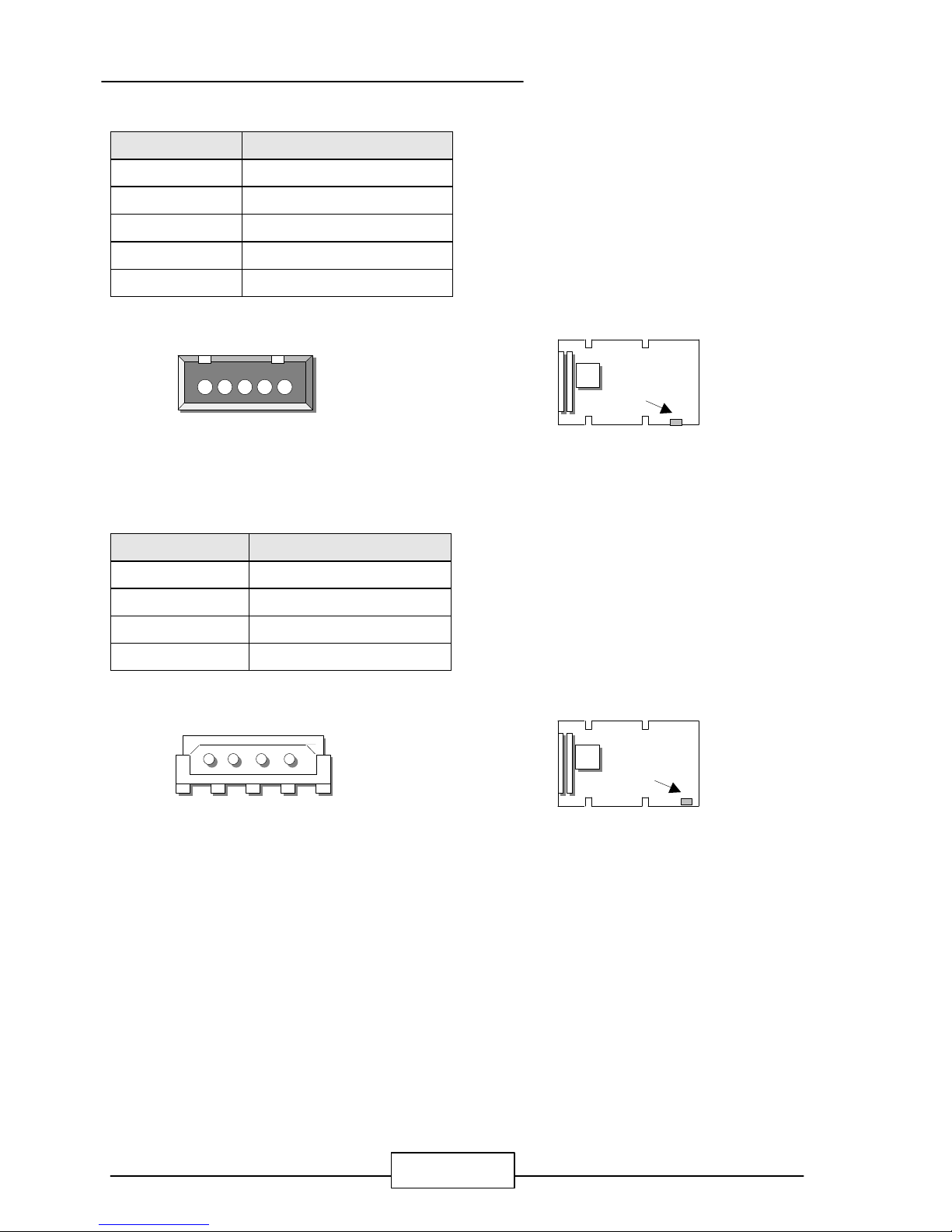
l PS1 : 5-Pin Power Connector
Pin No. Description
1 VCC
2 -5V
3 -12V
4 +12V
5 Ground
l PS2 : 4-Pin Power Connector
Pin No. Description
1 12V
2 Ground
3 Ground
4 5V
PS2
PS2
3 2 14
PS1
PS1
3 4 521
JUMPER SETTING AND CONNECTORS
EM586 / 24
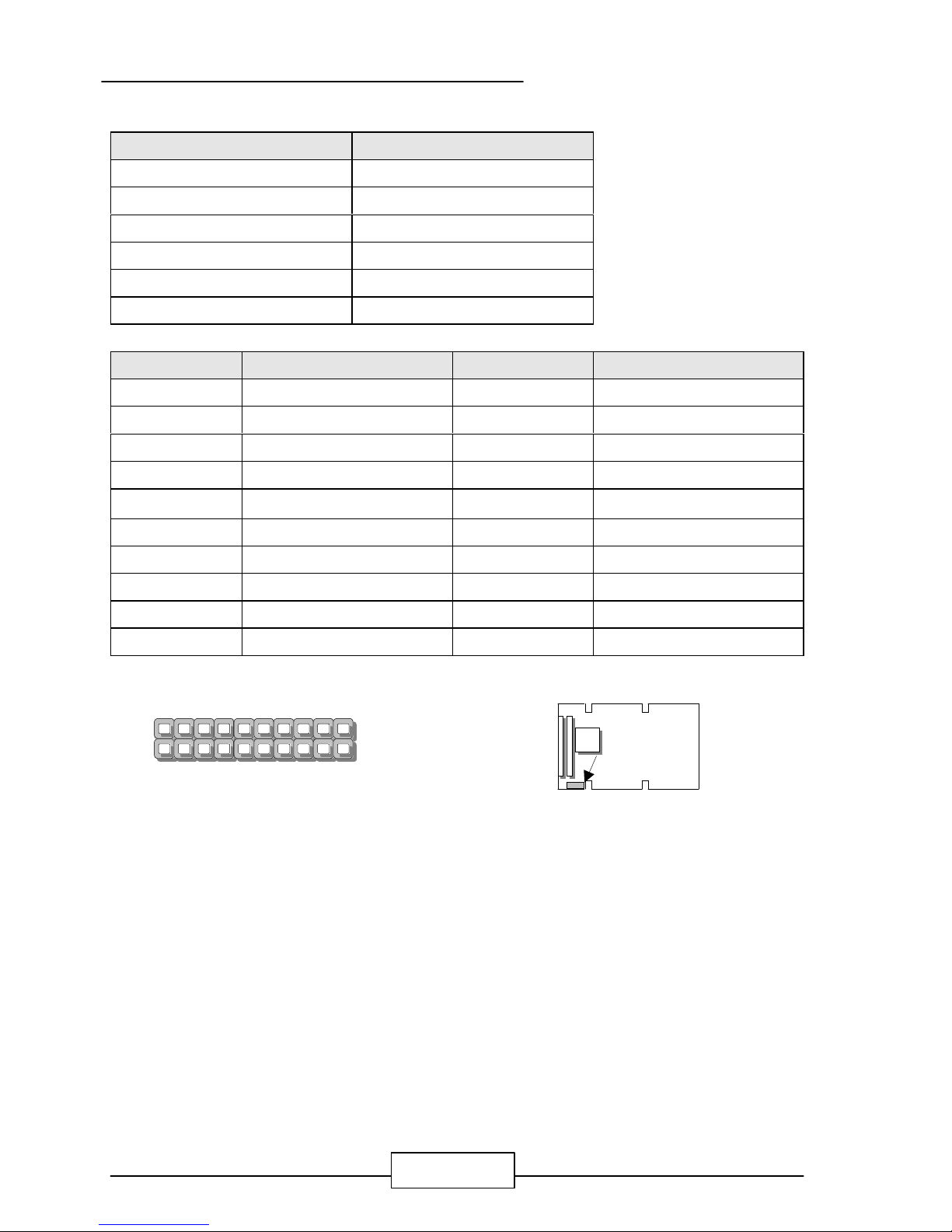
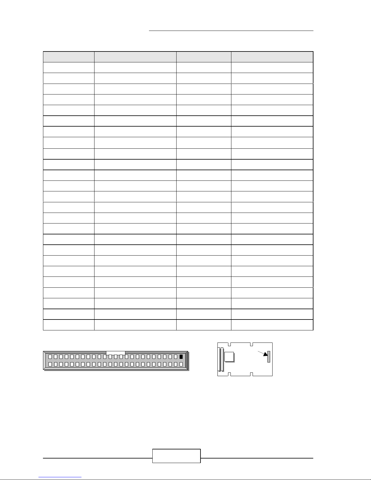
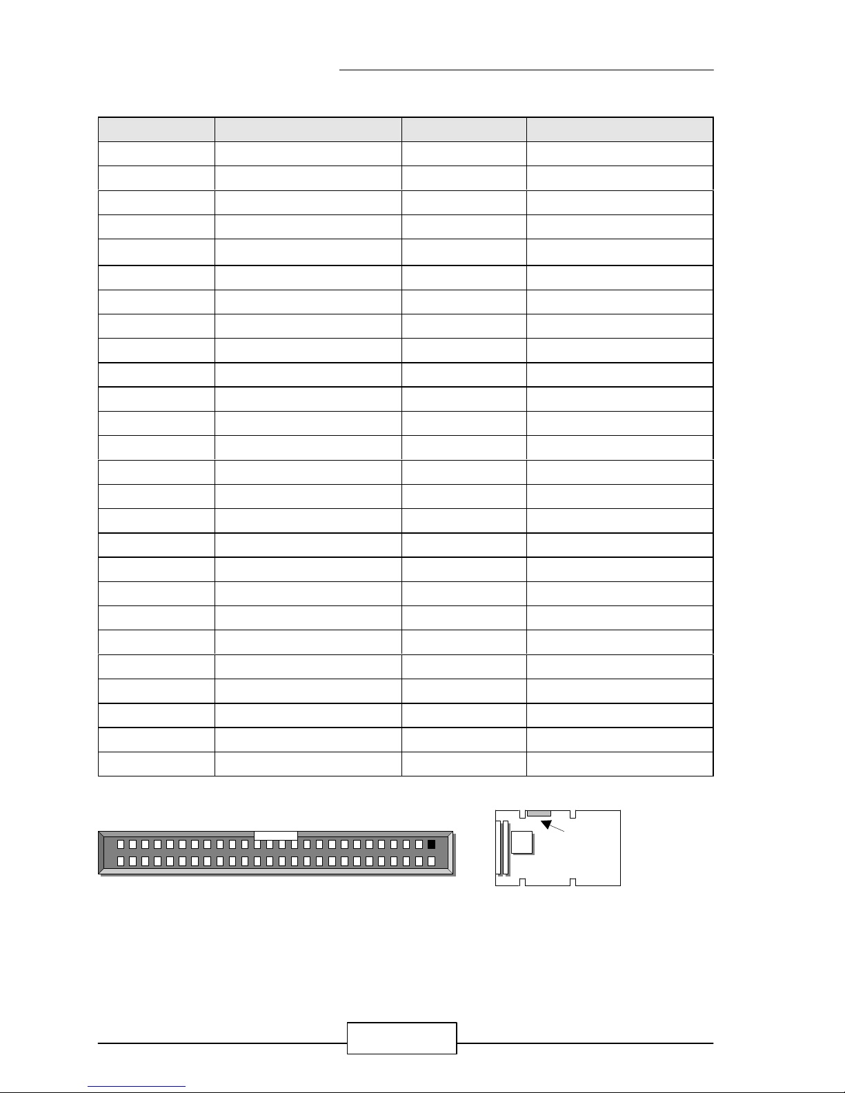
l CN1 : COM1 ~ COM4 Connector
Pin No. Description Pin No. Description
1 DCD1# 2 DSR1#
3 SIN1 4 RTS1#
5 SOUT1# 6 CTS1#
7 DTR1# 8 RI1#
9 COMGND 10 COMGND
11 DCD2# 12 DSR2#
13 SIN2 14 RTS2#
15 SOUT2# 16 CTS2#
17 DTR2# 18 RI2#
19 COMGND 20 COMGND
21 DCD3# 22 DSR3#
23 SIN3 24 RTS3#
25 SOUT3# 26 CTS3#
27 DTR3# 28 RI3#
29 COMGND 30 COMGND
31 NC 32 NC
33 NC 34 NC
35 COMGND 36 COMGND
37 DCD4# 38 DSR4#
39 SIN4 40 RTS4#
41 SOUT4# 42 CTS4#
43 DTR4# 44 RI4#
45 COMGND 46 COMGND
47 485TXD+ 48 485TXD49 485RXD+ 50 485RXD-
CN1
50
49 1
2
CN1
JUMPER SETTING AND CONNECTORS
EM586 / 25
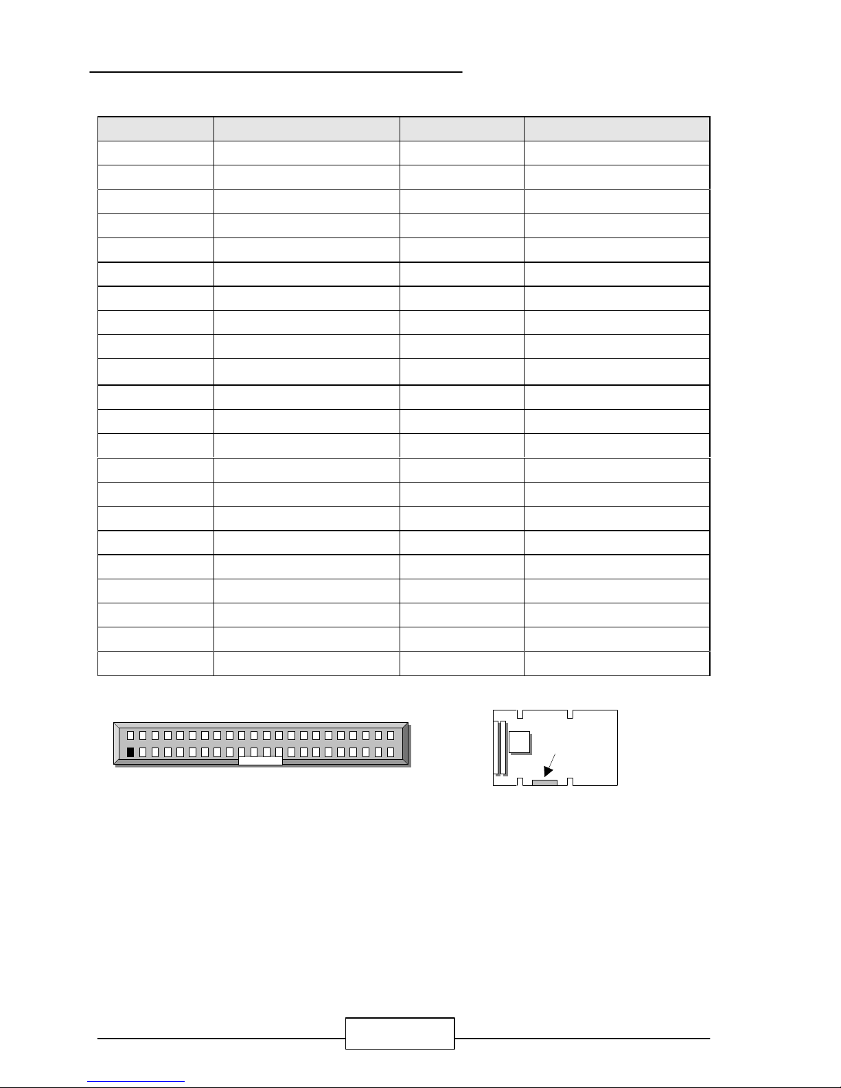
l CN2 : CD_IN, MIC_IN, LIN_IN, Mouse, Keyboard, USB1, USB2 Connector
Pin No. Description Pin No. Description
1 R-CDI 2 AGND1
3 L-CDI 4 AGND1
5 MIC-IN 6 AGND1
7 AGND1 8 NC
9 LIN-L 10 AGND1
11 NC 12 LIN-R
13 AGND1 14 AGND1
15 AGND1 16 HO-L
17 AGND1 18 AGND1
19 HO-R 20 AGND1
21 AGND1 22 LO-R
23 AGND1 24 AGND1
25 LO-L 26 AGND1
27 KB_GND 28 VCCF
29 MSDATA 30 MSCLK
31 KB_GND 32 VCCF
33 KBDATA 34 KBCLK
35 Ground 36 Ground
37 VUSB1 38 VUSB2
39 USB1- 40 USB241 USB1+ 42 USB2+
43 USGND 44 USGND
CN2
1
2 44
43
CN2
JUMPER SETTING AND CONNECTORS
EM586 / 26
l LCD1 : Panel LCD Connector ( Header )
Pin No. Description Pin No. Description
1 P0 2 P1
3 P2 4 P24
5 P3 6 P4
7 P25 8 Ground
9 P5 10 P6
11 P26 12 P7
13 P8 14 Ground
15 P27 16 P9
17 P10 18 P28
19 P11 20 Ground
21 P12 22 P29
23 P13 24 P30
25 P14 26 ENAVEE
27 P15 28 P31
29 P16 30 P17
31 P18 32 P32
33 Ground 34 SCLK
35 Ground 36 DE
37 FLM 38 LP
39 Ground 40 P19
41 P20 42 Ground
43 P21 44 P22
45 P33 46 P23
47 P34 48 NC
49 P35 50 ENAVDD
51 VCC 52 VCC
LCD1
LCD1
52
26 1
27
 Loading...