

Vox Power VCCM600 Series User Manual
VCCM600 Series
AC/DC conduction cooled configurable power supplies
User Manual
_____________________________________________________________________________________________________
VCCM600 Series User Manual | DOC6103r00 | Release date 02/03/2017
Vox Power Limited | Unit 2, Red Cow Interchange Estate, Ballymount, Dublin 22, D22 Y8H2, Ireland | T +353 1 4591161 | www.vox-power.com
Cool it your way. Conduction | Convection | Forced Air
4”x7”x1.61”
SMALL
600W
POWERFUL
SILENT
FAN-LESS
The VCCM600 series user manual has been prepared by our design team to assist qualified engineers in correctly
designing in the VCCM600 product into their application to achieve the best reliability and performance possible.
All specifications are believed to be correct at time of publishing. Vox Power Ltd reserves the right to make changes to any of its products and to change or improve any part of the
specification, electrical or mechanical design or manufacturing process without notice. Vox Power Ltd does not assume any liability arising out of the use or application of any of its
products and of any information to the maximum extent permitted by law. No license, express or implied, by estoppel or otherwise, to any intellectual property rights is granted by this
document or by any products of Vox Power Ltd. VOX POWER LTD DISCLAIMS ALL WARRANTIES AND REPRESENTATIONS OF ANY KIND WHETHER EXPRESS OR IMPLIED, INCLUDING, BUT
NOT LIMITED TO, IMPLIED WARRANTIES OF SUITABILITY, FITNESS FOR PURPOSE, MERCHANTABILITY AND NONINFRINGEMENT.
Please consult your local distributor or Vox Power directly to ensure that you have the latest revision before using the product and refer to the latest relevant user manual for further
information relating to the use of the product. Vox Power Ltd products are not intended for use in connection with life support s ystems, human implantations, nuclear facilities or systems,
aircraft, spacecraft, military or naval missile, ground support or control equipment used for the purpose of guidance navigation or direction of any aircraft, spacecraft or military or naval
missile or any other application where product failure could lead to loss of life or catastrophic property damage. The user will hold Vox Power Ltd harmless from any loss, cost or damage
resulting from its breach of these provisions.
VCCM600 Series Overview
The VCCM600 series of conduction cooled configurable power platform delivers a silent 600 Watts and up to 750 Watts of peak power for 5
seconds in a rugged 4” x 7” package and is the ultimate power solution for applications where reliability or audible noise are of concern. The
product combines the advantages of a modular power supply with the high reliability of a fan-less architecture. Depending on your application,
the VCCM600 can be configured as a conduction, convection or forced air cooled solution and this versatility allows the unit to be seamlessly
integrated across a vast range of applications, which makes it perfect for standardising your power platform.
Designed with highest reliability and versatility in mind, the VCCM600 is suitable for applications ranging from the most controlled environments
to the harshest conditions. Each configured modular solution can accommodate up to 4 isolated DC output modules which utilize 100% SMT
components for increased reliability. Standard features include full output voltage adjust range, externally controllable voltage and current and
series & paralleling of outputs. The unique design approach and heat dissipation techniques allows the unit to be mounted in virtually any
orientation giving system designers even more flexibility. The series is approved to latest safety and EMC standards and features market leading
specifications and design in application support.

2 | Page
VCCM600 Series User Manual | DOC6103r00 | Release date 02/03/2017
Vox Power Limited | Unit 2, Red Cow Interchange Estate, Ballymount, Dublin 22, D22 Y8H2, Ireland | T +353 1 4591161 | www.vox-power.com
Contents
VCCM600 Series Overview 1
Part Numbers and Ordering Information 3
Important installation information 4
Theory of Operation 5
Input Module Operation 6
Input Module Protections 7
Efficiency Performance 8
Power Ratings 9
System Cooling 9
Signalling 13
Output Module Operation (A, B, C & D) 15
Advanced Output Module Features 18
Series Connected Outputs 22
Parallel Connected Outputs 23
Mechanical Dimensions and Mounting 26
Connector details 27
Safety 28
EMC Compliance 29
Reliability 31
Configuring Your VCCM Product 32
Accessories 37
3 | Page
VCCM600 Series User Manual | DOC6103r00 | Release date 02/03/2017
Vox Power Limited | Unit 2, Red Cow Interchange Estate, Ballymount, Dublin 22, D22 Y8H2, Ireland | T +353 1 4591161 | www.vox-power.com
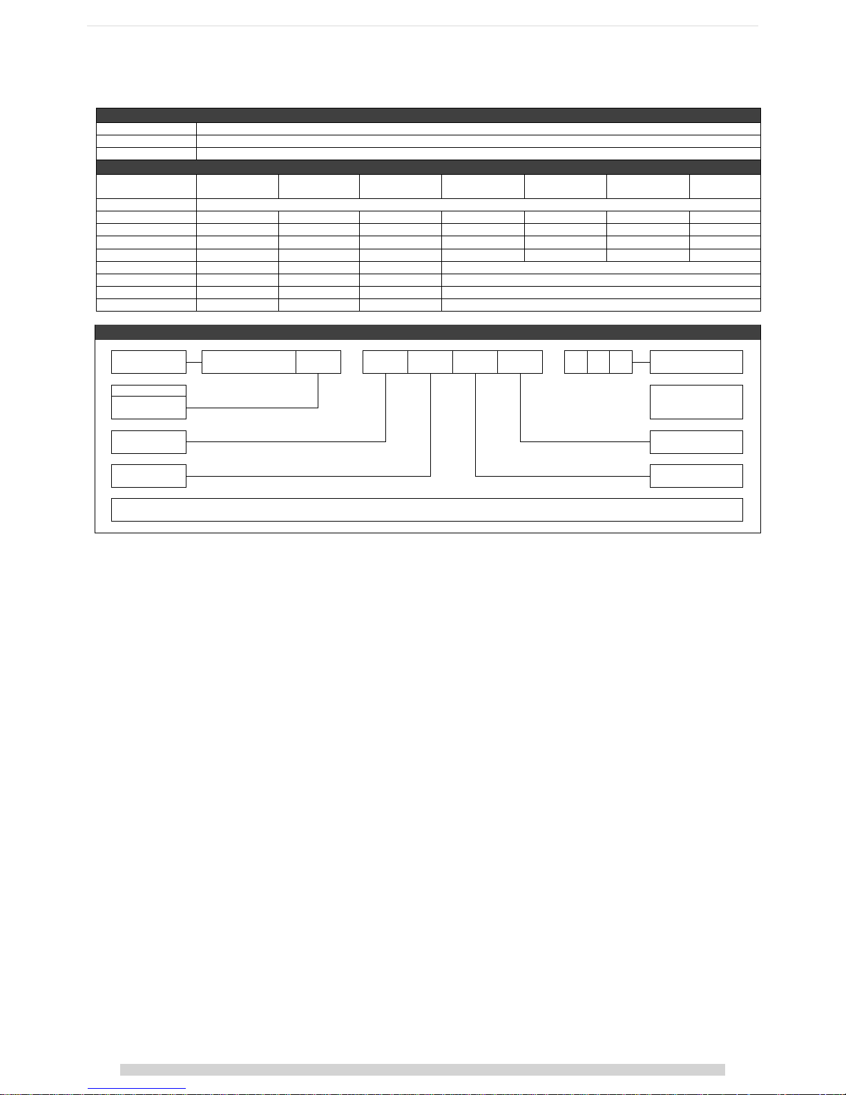
Part Numbers and Ordering Information
INPUT MODULES
Input Module
Details
VCCM600S
600 Watt Input Module with ITE Approvals (IEC60950 Edition 2)
VCCM600M
600 Watt Input Module with Medical Approvals (IEC60601 Edition 3 + IEC60601-1-2 Edition 4 EMC)
OUTPUT MODULES
Module
Nominal voltage
Rated current
Rated Power
Adjustment
range
Load regulation
Line regulation
OVP
OP 0
Unused slots
OP A
5V
25A
125W
1.5V-7.5V
±50mV
±0.1%Vnom
9V
OP B
12V
15A
150W
4.5V-15V
±100mV
±0.1%Vnom
18V
OP C
24V
7.5A
150W
9V-30V
±150mV
±0.1%Vnom
36V
OP D
48V
3.5A
150W
18V-58V
±300mV
±0.1%Vnom
66V
OP E
5v
100A
500W
Future release (4 slot module)
OP F
12v
50A
600W
Future release (4 slot module)
OP G
24V
25A
600W
Future release (4 slot module)
OP H
48V
12.5A
600W
Future release (4 slot module)
PART NUMBERING SYSTEM
VCCM Input
Module
VCCM600 S - A B C D - 0 0 0
Factory use
Product Type
USE '0' for unused slots.
S - Standard
M - Medical
Slot 1 - Output #
Slot 4 - Output #
Slot 2 - Output #
Slot 3 - Output #
Contact your Distributor or Vox Power for sp ecial configuration requirem ents. The factory may allocate a 3-digit suffix to identify such r equirements.

4 | Page
VCCM600 Series User Manual | DOC6103r00 | Release date 02/03/2017
Vox Power Limited | Unit 2, Red Cow Interchange Estate, Ballymount, Dublin 22, D22 Y8H2, Ireland | T +353 1 4591161 | www.vox-power.com
Important installation information
The VCCM600 series of configurable power supplies are intended for use within end customer applications which restrict access to un-authorized personnel. The
instructions in this manual and all warning labels on the product must be adhered to carefully.
SAFETY
The VCCM600S and VCCM600M series are designed in accordance with the relevant safety requirements of UL60950-1, IEC/EN60950-1, UL60601-1, IEC/EN606011, CSA22.2 no 601-1, Low voltage Directive LVD 2014/35/EU and EMC directive EMC 2014/30/EU.
All VCCM600 series power supplies must be installed correctly in a controlled environment which restricts access to any un-authorised personnel. Equipment and
system manufacturers must protect service personnel against unintentional contact with the output terminals.
HAZZARDS
Dangerous voltages are present within the power supply. It should only be handled by qualified personnel when the power supply has been disconnected from
the mains supply voltage for more than 3 minutes.
External surfaces of the power supply may become extremely hot during and after operation. Appropriate care should be taken.
If series and/or parallel combinations of outputs exceed safe voltage and/or energy levels, the final equipment manufacturer must provide the appropriate
protection for both users and service personnel.
DE-RATINGS
Ambient Temperature
The input module power must be de-rated by 2.5%/°C above 50°C ambient up to a maximum ambient temperature of
70°C.
Baseplate Temperature
The output module power and current must be de-rated by 2.5%/°C above 85°C baseplate up to a maximum baseplate
temperature of 105°C.
Input Voltage
The input module power must be de-rated by 5W/VRMS below120 VRMS (600W @ 120 VRMS, 450W @ 90 VRMS)
Remember to take the appropriate de-rating into consideration before specifying any VCCM600 power supply for an application. If in any doubt, please contact
Vox Power directly or your local Vox Power representative.
HEALTH AND SAFETY
To comply with section 6 of the health and safety at work act, a label that is clearly visible to service personnel must be placed on the final equipment. These
labels warn that surfaces of the power supply may be hot and should not be touched when the product is operating.
FUSING
The power supply has internal dual pole fusing. One fuse in each line.
Fuses should only be replaced by authorised personnel and to ensure continued protection against risk of fire, fuses must be replaced with the same type and
rating of fuse.
For DC operation, an appropriately rated DC fuse must be included in the end application.
SERVICING
The power supply contains no user serviceable parts. Repairs must be carried out by authorised personnel only. Contact Vox Power for further information.
APPROVAL LIMITATIONS – NORTH AMERICA
When this product is used with 180VAC–253VAC mains where no neutral is present, connect the two live wires to L (Live) and N (Neutral) on the input connector.
COOLING
For proper operation of the power supply, the user must ensure sufficient cooling to maintain all component temperatures within specifications. A thorough
review of the user manual should be carried out for details of thermal performance.
EARTH TERMINAL MARKING
To comply with the requirements of UL60950-1, IEC/EN60950-1, CSA22.2 no. 60950-1, UL60601-1, IEC/EN60601-1, CSA22.2 no 601-1 where the incoming wiring
earth is intended for connection as the main protective earth conductor and where the terminals for such a connection is not supplied on a component or
subassembly, the user shall add an appropriate label displaying a protective earth symbol in accordance with 60417-2-IEC-5019 directly adjacent to the terminal.
The label should be durable and legible and should withstand the 15 second rub test as per UL60950-1 section 1.7.15.
WARRANTY
Contact your sales agent or Vox Power for product repairs. See Vox Power standard terms and conditions for warranty conditions.
PRODUCT LABELS
The external product label contains information relevant to the power system. The label contains input voltage, maximum input current, input frequency,
maximum output power, fuse rating and type, serial number, approvals and product part number in form VCCM600x-yyyy-zzz.
VCCM OUTPUT MODULES
Each output module label contains information relevant to that output. The label contains voltage adjustment range, maximum output current, serial number,
approvals and the part number in format OPx.
OTHER
• A label warning that external surfaces are hot during operation and that the unit should be allowed to cool down properly should be placed on the
unit where such a label is clearly visible.
• The VCCM600 series is designed to comply with EMC standards but it does not imply that the end system will comply.
• To prolong the life of the unit, use in dust free environment.
• Units can sometimes be damaged during transit. In the event of transit damage, DO NOT connect power to the unit. Contact your sales agent or Vox
Power.
• Always use adequately sized cables and ensure good crimp connections. Use cable supports to minimise stress on connectors.
• Avoid excessive shock or vibration.
5 | Page
VCCM600 Series User Manual | DOC6103r00 | Release date 02/03/2017
Vox Power Limited | Unit 2, Red Cow Interchange Estate, Ballymount, Dublin 22, D22 Y8H2, Ireland | T +353 1 4591161 | www.vox-power.com
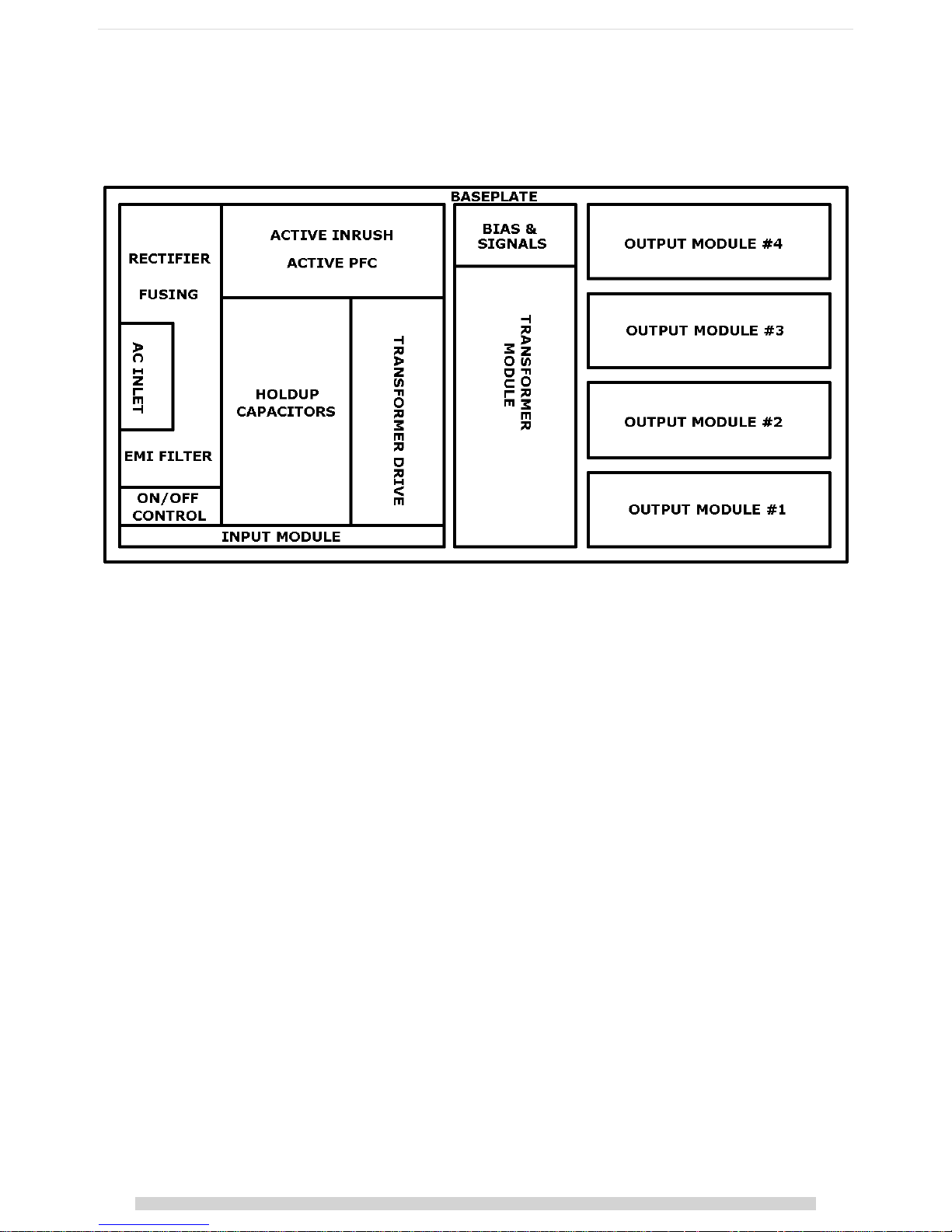
Theory of Operation
The diagram below outlines the topology and major internal components of a fully assembled VCCM600 configurable power supply. Four output slots are
provided and can be populated by any combination of
output modules
. The remaining components in the block diagram are housed in the
input
and
transformer modules
.
The
input module
is responsible for receiving the AC mains line voltage and converting it to an appropriate DC voltage whilst providing protection from AC line
disturbances and preventing excessive EMI emissions and current harmonics. The integrated EMI filter attenuates high frequency current emissions to levels
below EN55022 class B. It also provides dual pole fusing, one fuse in each conductor and protection from line disturbances as outlined in EN61000.
Inrush current is controlled by a resistive element upon initial connection to the AC line. Once the internal capacitances have been charged, the resistive element
is bypassed to reduce losses.
Active Power Factor Correction (PFC) is used to ensure an accurate input current waveform with extremely low harmonic content, exceeding the requirements of
EN61000. This stage also provides active input current limiting which prevents overloading of the input stage while maintaining high power factor.
The output of the PFC stage charges the hold-up electrolytic capacitors which store enough energy to allow the VCCM600 configured product to continue
operating during minor line disturbances. Long lifetime and high temperature capacitors are used which ensures extended lifetime and product reliability.
A highly efficient zero voltage switching circuit is used to drive the isolated transformer from the hold-up capacitors. The output modules connect to the
transformer secondary and provide safe isolated power to a high performance synchronous rectifier power converter. This power converter is controlled using
the latest analog control technology to produce superior output performance in a miniature size.
6 | Page
VCCM600 Series User Manual | DOC6103r00 | Release date 02/03/2017
Vox Power Limited | Unit 2, Red Cow Interchange Estate, Ballymount, Dublin 22, D22 Y8H2, Ireland | T +353 1 4591161 | www.vox-power.com
Input Module Operation
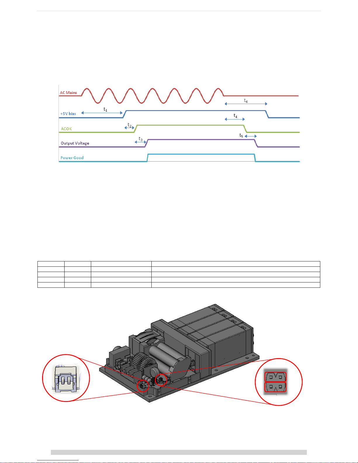
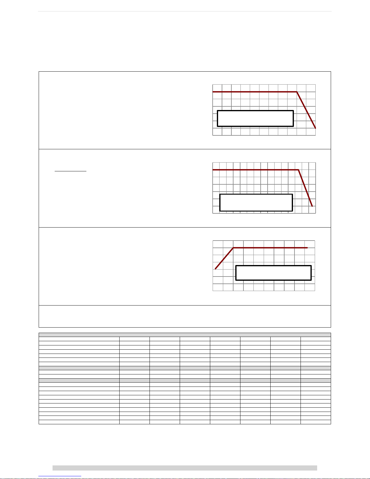
Startup & Shut Down
The VCCM input module operates from a universal input voltage range and starts automatically upon application of adequate AC mains voltage (>84Vrms). After
a short delay, the global 5V bias supply starts and the ACOK signal goes high to indicate that the mains voltage is present and input stage is operating correctly.
Once the ACOK signal is high, the output modules turn on and deliver power to the application loads. The power good signals will indicate that the output
voltages are within specification. The diagram below shows the normal start up/shut down sequence and gives typical timings.
Typical timing values: t
1
ϕ ≤2000 ms, t2ϕ ≤400 ms, t3ϕ ≤600 ms, t4ϕ ≥15 ms, t5ϕ ≥5ms (minimum), t6ϕ ≥100 ms
When the AC mains voltage is removed, the internal hold-up capacitors will supply power to the load for typically 20 ms (t
4+t5
) at maximum power. The ACOK
signal will go low at least 5ms before the output voltages fall below the power good threshold level. This allows the application to prepare for the impending loss
of power. The 5V bias supply will remain on for typically 100ms, after the output modules have turned off.
Standby control
The unit may be completely shut down by shorting (<10Ω) the terminals of J2. The unit will restart once the short is released.
The control uses transformer coupled pluses to detect the short and is fully isolated to 2xMOPP. The voltage present on J2 ranges from +3.3V to -0.8V with a peak
current of 15mA. In active mode, the control is pulsed every 1.3mS while in standby mode the control is pulsed every 400mS. A signal MOSFET or switch may be
used to activate this control. This shutdown will not generate the ACOK warning signal.
Programmable start-up state
The start-up and standby control logic can be inverted by shorting J11 with a jumper. The functionality is shown in the table below.
J11
J2
Operational mode
Comments
Open
Open
NORMAL
Default. Unit will start into NORMAL mode
Open
Closed
STANDBY
<1W power consumption
Closed
Open
STANDBY
Unit will start into STANDBY mode. <1W power consumption
Closed
Closed
NORMAL
Note - J12 is reserved for internal use. Do not short J12
J11 LOC ATION
J2 LOCATION
- +
J11
J12

7 | Page
VCCM600 Series User Manual | DOC6103r00 | Release date 02/03/2017
Vox Power Limited | Unit 2, Red Cow Interchange Estate, Ballymount, Dublin 22, D22 Y8H2, Ireland | T +353 1 4591161 | www.vox-power.com
Hold-up
For short line distubances (<20ms), the output voltages will not be affected*. However, the ACOK signal may still go low to warn that there is an impending loss
of output power. The ACOK signal will return to the high state once the unit has recovered from the disturbance.
*Output modules that are adjusted above the hold-up voltage (as detailed in their respective datasheets), may experience a dip in voltage but never below the
hold-up voltage specified.
No Load Power/Standby Power Consumption
The no-load power consumption of the VCCM600 series PSU is extremely low when compared to similar configurable power supplies. With the output modules
enabled the unit typically only requires less than 15W with no output load. To reduce the no-load power further the outputs can be disabled using the inhibit
pins. With the outputs disabled the unit typically requires less than 10W. When the unit is in the standby (latched off) state, the power consumption is less than
1W.
Peak Power capability
The input module can provide a peak output power of up to 750W for a period of up to 5 seconds, provided the input current remains below the over current
protection threshold. Peaks of power lower than 750W can be supported for longer times provided the excess watt-seconds are equivalent. For example, 750W
peak for 5 seconds is an excess power of 150W*5s = 750Ws. 650W can be supported for 750Ws/50W = 15s. When using peak power capability, the user must
ensure the average power remains within ratings. Note that input module de-ratings apply to both rated power and peak power.
Input Module Protections
Over current protection (OCP)
The input module is protected from excessive input current by means of an over current protection circuit which limits the input current to approximately 7Arms.
If the OCP threshold is exceeded the unit may shut down and attempt to automatically restart. This shutdown will generate the usual ACOK warning.
Under voltage protection (UVP) & Brown-Out Protection (BOP)
The input module is protected from excessively low input voltages by under voltage and brown out protection circuits that senses the input line voltage. The
under-voltage protection circuit maintains the unit in standby mode until the input voltage rises above the UVP threshold as detailed in the datasheet. Once the
unit is active, the brown out protection monitors the input voltage and shuts down the unit when input voltage goes below approximately 60Vrms. This
shutdown will generate the usual ACOK warning. The unit will restart once the input voltage increases above the UVP threshold.
Over Temperature Protection (OTP)
The input module is protected from excessive temperatures by means of various internal temperature sensors. If temperature thresholds are exceeded the entire
unit may latch off, with no ACOK warning. To re-enable the unit, it must be allowed to cool, then either disconnect the AC mains for approximately 20 seconds, or
toggle the standby control on J2.
Over Power Protection (OPP)
The input module is protected from excessive power by means of an over power protection circuit. Should the rated power be exceeded the unit will shut down
and attempt to recover automatically. This shutdown will not generate the usual ACOK warning.

8 | Page
VCCM600 Series User Manual | DOC6103r00 | Release date 02/03/2017
Vox Power Limited | Unit 2, Red Cow Interchange Estate, Ballymount, Dublin 22, D22 Y8H2, Ireland | T +353 1 4591161 | www.vox-power.com
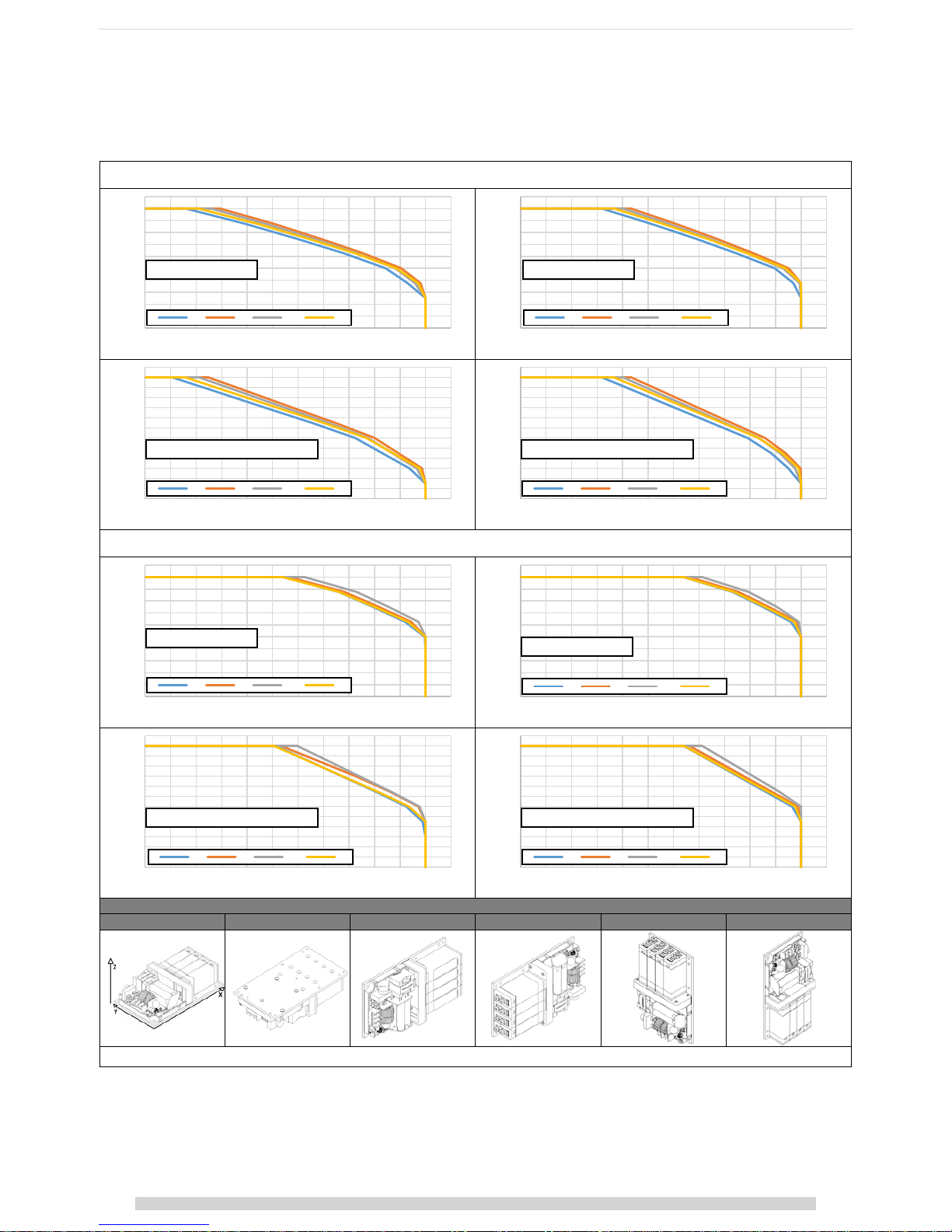
Efficiency Performance
The efficiency of the configured VCCM600 product is dependent on parameters such as input line voltage, load level and on the combination of output modules.
The plots below show typical efficiencies of a VCCM600 product fitted with all modules A, B, C or D. The plots cover the full load and line voltage range. All
modules are adjusted to nominal voltages and are equally loaded.
An estimate of the overall efficiency for any configured system may be obtained from these graphs.
0.73
0.74
0.75
0.76
0.77
0.78
0.79
0.80
0.81
0.82
0.83
0.84
0.85
0.86
0.87
0.88
0.89
0.90
0.91
0 50 100 150 200 250 300 350 400 450 500 550 600
Efficiency
Output Power (Watts)
Typical Load Efficiency at 120V
RMS
input voltage
OPA OPB OPC OPD
0.73
0.74
0.75
0.76
0.77
0.78
0.79
0.80
0.81
0.82
0.83
0.84
0.85
0.86
0.87
0.88
0.89
0.90
0.91
0 50 100 150 200 250 300 350 400 450 500 550 600
Efficiency
Output Power (Watts)
Typical Load Efficiency at 220V
RMS
input voltage
OPA OPB OPC OPD
0.73
0.74
0.75
0.76
0.77
0.78
0.79
0.80
0.81
0.82
0.83
0.84
0.85
0.86
0.87
0.88
0.89
0.90
0.91
0 50 100 150 200 250 300 350 400 450
Efficiency
Output Power (Watts)
Typical Load Efficiency at 85V
RMS
input voltage
OPA OPB OPC OPD
0.73
0.74
0.75
0.76
0.77
0.78
0.79
0.80
0.81
0.82
0.83
0.84
0.85
0.86
0.87
0.88
0.89
0.90
0.91
80 100 120 140 160 180 200 220 240 260
Efficiency
InputVoltage (V
RMS
)
Typical Line Efficiency at maximum rated power
OPA OPB OPC OPD
9 | Page
VCCM600 Series User Manual | DOC6103r00 | Release date 02/03/2017
Vox Power Limited | Unit 2, Red Cow Interchange Estate, Ballymount, Dublin 22, D22 Y8H2, Ireland | T +353 1 4591161 | www.vox-power.com
Power Ratings
VCCM600 series products must always be operated within stated operating limits. Equipment manufacturers and other users must take the appropriate de-rating
into account when specifying a unit for the intended application. If in doubt, contact your sales representative or Vox Power for assistance.
There are three main de-ratings for the VCCM600 series of configurable power supplies when used in a conduction cooled application,
1. Ambient air temperature
(1)
Ambient air temperature de-ratings apply to the input module rated and peak
power only.
(3)
The input module must be de-rated by 2.5% per degree Celsius above 50°C, up to
a maximum of 70°C.
2. Baseplate temperature
(2)
Baseplate temperature de-ratings apply to output module rated power, peak
power and rated current
, and bias supply power.
The output module parameters must be de-rated by 2.5% per degree Celsius
above 85°C, up to a maximum of 105°C.
3. Input line voltage
Input line voltage de-ratings apply to the rated power and peak power for both
the input module and output module.
(3)
All parameters must be de-rated by 2.5% for every 3 volts below 120Vrms, down
to a minimum of 85Vrms.
Notes:
1. Ambient air temperatu re is the air temperature im mediately surrounding the PSU.
2. Baseplate temperature is measur ed at baseplate temperature sensing location TS1.
3. A normalized value of 1 is equivalent to 100%.
4.
Input line voltage deratings are cumulative with temperature deratings.
Examples of power ratings calculation for various input voltages, ambient temperatures and baseplate temperatures
1 2 3 4 5 6
7
VIN (V
RMS
)
120
85
85
120
120
100
120
Normalised VIN Rating [A]
1
0.708
0.708 1 1
0.833
1
T
AMBIENT
(⁰C)
70
50
70
50
60
60
50
Normalised T
AMBIENT
Rating [B]
0.5 1 0.5 1 0.75
0.75
1
T
BASE
(⁰C)
85
85
85
95
105
95
105
Normalised T
BASE
Rating [C]
1 1 1
0.75
0.5
0.75
0.5
Normalised Total input rating [A*B = D]
0.5
0.708
0.354 1 0.75
0.624
1
Normalised Total output rating [A*C = E]
1
0.708
0.708
0.75
0.5
0.624
0.5
Input module P
RATED/PEAK
[600W/750W*D]
300/375
424.8/531
212.4/265.5
600/750
450/562.5
374.4/468
600/750
Bias supply power [5W*C]
5 5 5
3.75
2.5
3.75
2.5
OPA P
RATED/PEAK
[125W/187.5W*E]
125/187.5
88.5/132.75
88.5/132.75
93.75/140.625
62.5/93.75
78/117
62.5/93.75
OPA I
RATED
[25A*C]
25
25
25
18.75
12.5
18.75
12.5
OPB P
RATED/PEAK
[150W/225W*E]
150/225
106.2/159.3
106.2/159.3
112.5/168.75
75/112.5
93.6/140.4
75/112.5
OPB I
RATED
[15A*C]
15
15
15
11.25
7.5
11.25
7.5
OPC P
RATED/PEAK
[150W/225W*E]
150/225
106.2/159.3
106.2/159.3
112.5/168.75
75/112.5
93.6/140.4
75/112.5
OPC I
RATED
[7.5A*C]
7.5
7.5
7.5
5.625
3.75
5.625
3.75
OPD P
RATED/PEAK
[150W/217.5W*E]
150/217.5
106.2/154
106.2/154
112.5/163.125
75/108.75
93.6/135.72
75/108.75
OPD I
RATED
[3.75A*C]
3.75
3.75
3.75
2.8125
1.875
2.8125
1.875
System Cooling
0.4
0.5
0.6
0.7
0.8
0.9
1
1.1
-40 -30 -20 -10 0 10 20 30 40 50 60 70
Normalised output powe r r a t ing
Ambient Temperature (Celcius)
Ambient Temperature Derating
Derate at 2.5% per degree celcius
above 50 degree celcius
0.4
0.5
0.6
0.7
0.8
0.9
1
1.1
80 100 120 140 160 180 200 220 240 260 280
Normalised Output P owe r r a ting
Input Voltage (RMS)
Input Line voltage Derating
Derate at 2.5% per every
3 volts below 120Vrms
0.4
0.5
0.6
0.7
0.8
0.9
1
1.1
-40 -30 -20 -10 0 10 20 30 40 50 60 70 80 90 100 110
Normalised Power & Current Rating
Baseplate Temperature (Celcius)
Temperature Derating
Derate at 2.5% per degree celcius
above 85 degree celcius
10 | Page
VCCM600 Series User Manual | DOC6103r00 | Release date 02/03/2017
Vox Power Limited | Unit 2, Red Cow Interchange Estate, Ballymount, Dublin 22, D22 Y8H2, Ireland | T +353 1 4591161 | www.vox-power.com
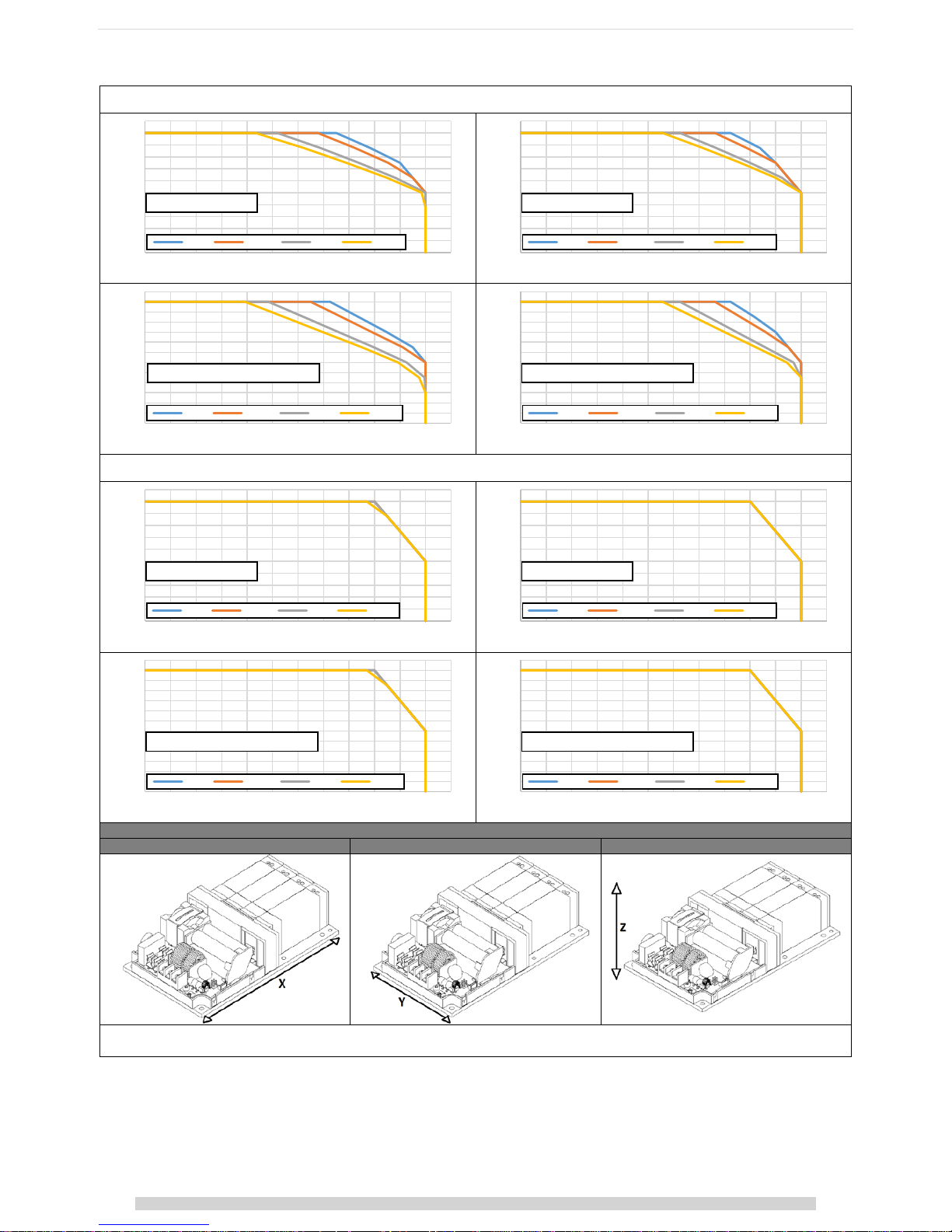
The power ratings shown in the previous section are for conduction cooling, however the unit may be operated with forced air cooling, convection cooling or
combinations of all three. To assist in specifying the product for these applications, the typical thermal performance has been characterised under controlled
conditions. The ratings achieved are based on maintaining the baseplate temperature within the conduction cooled ratings specified on page 9.
CONVECTION PERFORMANCE
Natural Convection, No Heatsink, Free Air, Mounting Orientations A/B/C/D/E/F
CONVECTION PERFORMANCE WITH HEATSINK
(1)
Natural Convection, With Heatsink, Free Air, Mounting Orientations A/B/C/D/E/F
Orientation definitions
A B C D E
F
Orientation
definitions
Notes
1. Standard Vox heatsin ks type 1 and type 2 used. Type 1 u sed for mounting orientation s A, B, E and F. Type 2 used for mounting orientations A, B, C and D.
0
50
100
150
200
250
300
350
400
450
500
550
-40 -30 -2 0 -10 0 10 20 30 40 50 60 70 80
Pout
Ambient Temperature
OPA 120Vin, 4x5Vout
A B CD EF
0
50
100
150
200
250
300
350
400
450
500
550
-40 -30 -2 0 -10 0 10 20 30 40 50 60 70 80
Pout
Ambient Temperature
OPA 220Vin, 4x5Vout
A B CD EF
0
50
100
150
200
250
300
350
400
450
500
550
600
650
-40 -30 -2 0 -10 0 10 20 30 40 50 60 70 80
Pout
Ambient Temperature
OPB/C/D 120Vin, 4x10/20/40Vout
A B CD EF
0
50
100
150
200
250
300
350
400
450
500
550
600
650
-40 -30 -2 0 -10 0 10 20 30 40 50 60 70 80
Pout
Ambient Temperature
OPB/C/D 220Vin, 4x10/20/40Vout
A B CD EF
0
50
100
150
200
250
300
350
400
450
500
550
-40 -30 -2 0 -10 0 10 20 30 40 50 60 70 80
Pout
Ambient Temperature
OPA 120Vin, 4x5Vout
A B CD EF
0
50
100
150
200
250
300
350
400
450
500
550
-40 -30 -2 0 -10 0 10 20 30 40 50 60 70 80
Pout
Ambient Temperature
OPA 220Vin, 4x5Vout
A B CD EF
0
50
100
150
200
250
300
350
400
450
500
550
600
650
-40 -30 -2 0 -10 0 10 20 30 40 50 60 70 80
Pout
Ambient Temperature
OPB/C/D 120Vin, 4x10/20/40Vout
A B CD EF
0
50
100
150
200
250
300
350
400
450
500
550
600
650
-40 -30 -2 0 -10 0 10 20 30 40 50 60 70 80
Pout
Ambient Temperature
OPB/C/D 220Vin, 4x10/20/40Vout
A B CD EF
11 | Page
VCCM600 Series User Manual | DOC6103r00 | Release date 02/03/2017
Vox Power Limited | Unit 2, Red Cow Interchange Estate, Ballymount, Dublin 22, D22 Y8H2, Ireland | T +353 1 4591161 | www.vox-power.com
FORCED AIR PERFORMANCE
No Heatsink, Air Direction X or Y at 2MS-1/1.5MS-1/1MS-1/0.5MS-1
FORCED AIR PERFORMANCE WITH HEATSINK
(2)
With Heatsink, Air Direction X or Y at 2MS-1/1.5MS-1/1MS-1/0.5MS-1
Airflow definitions
X Y Z
Notes
1. Each 0.5MS-1 is approximatel y 100LFM. Eg. 2MS-1 ≈ 400LFM, 1.5MS-1 ≈ 300LFM etc.
2. Standard Vox heatsin ks type 1 and type 2 used. Type 1 u sed for airflow direction X. Type 2 used for airflow direction Y.
The ratings provided above are for guidance only and all VCCM600 configured solutions must be evaluated in the end application to ensure the conditions set
out in the power ratings section are met.
0
50
100
150
200
250
300
350
400
450
500
550
-40 -30 -2 0 -10 0 10 20 30 40 50 60 70 80
Pout
Ambient Temperature
OPA 120Vin, 4x5Vout
2MS-1 1.5MS-1 1MS-1 0.5MS-1
0
50
100
150
200
250
300
350
400
450
500
550
-40 -30 -2 0 -10 0 10 20 30 40 50 60 70 80
Pout
Ambient Temperature
OPA 220Vin, 4x5Vout
2MS-1 1.5MS-1 1MS-1 0.5MS -1
0
50
100
150
200
250
300
350
400
450
500
550
600
650
-40 -30 -2 0 -10 0 10 20 30 40 50 60 70 80
Pout
Ambient Temperature
OPB/C/D 120Vin, 4x10/20/40Vout
2MS-1 1. 5MS-1 1MS-1 0.5MS-1
0
50
100
150
200
250
300
350
400
450
500
550
600
650
-40 -30 -2 0 -10 0 10 20 30 40 50 60 70 80
Pout
Ambient Temperature
OPB/C/D 220Vin, 4x10/20/40Vout
2MS-1 1. 5MS-1 1MS-1 0.5MS-1
0
50
100
150
200
250
300
350
400
450
500
550
-40 -30 -2 0 -10 0 10 20 30 40 50 60 70 80
Pout
Ambient Temperature
OPA 120Vin, 4x5Vout
2MS-1 1.5MS-1 1M S-1 0.5MS-1
0
50
100
150
200
250
300
350
400
450
500
550
-40 -30 -2 0 -10 0 10 20 30 40 50 60 70 80
Pout
Ambient Temperature
OPA 220Vin, 4x5Vout
2MS-1 1.5MS -1 1MS-1 0.5MS-1
0
50
100
150
200
250
300
350
400
450
500
550
600
650
-40 -30 -2 0 -10 0 10 20 30 40 50 60 70 80
Pout
Ambient Temperature
OPB/C/D 120Vin, 4x10/20/40Vout
2MS-1 1.5MS-1 1MS-1 0.5M S-1
0
50
100
150
200
250
300
350
400
450
500
550
600
650
-40 -30 -2 0 -10 0 10 20 30 40 50 60 70 80
Pout
Ambient Temperature
OPB/C/D 220Vin, 4x10/20/40Vout
2MS-1 1. 5MS-1 1MS-1 0.5MS-1
12 | Page
VCCM600 Series User Manual | DOC6103r00 | Release date 02/03/2017
Vox Power Limited | Unit 2, Red Cow Interchange Estate, Ballymount, Dublin 22, D22 Y8H2, Ireland | T +353 1 4591161 | www.vox-power.com
Specifying the VCCM600 product for convection or forced air cooling
To specify a VCCM600 series product for an end application, the required output power, minimum input line voltage, maximum ambient, mounting orientation
and air flow rate (if applicable) should be determined. Check the requirements against the closest characteristic plot from the tables above to ensure ratings can
be achieved. Be conservative when specifying the product as convection and forced air cooling can be highly dependent on the end application enclosure and
power supply mounting. The estimated performance must be verified in the end application and temperatures may exceed predicted levels. It is also important
to note that ambient temperature refers to the ambient temperature immediately surrounding the PSU. If the PSU is mounted within an enclosure the enclosure
ambient temperature is likely to be higher than the external air ambient temperature.
Evaluating the VCCM600 product in the end application
To ensure the product is operating within its ratings in the end application the following procedure should be performed during the design stage.
1. Install a thermocouple in position TS1 of the product. (See Mechanical dimensions and mounting for details.) The thermocouple wire should exit on
the top side between slots 2 and 3. The bottom side should be flush for heatsink mounting if necessary. Glue should be used to hold the
thermocouple in place.
2. Setup the application in worst case conditions, considering Input line voltage, Output power, ambient temperature, airflow and cooling restrictions.
3. Power the system and monitor the baseplate temperature until it reaches steady state.
4. Ensure that under worst case conditions, the baseplate temperature cannot exceed the rated temperature as outlined in the power ratings section of
this manual.
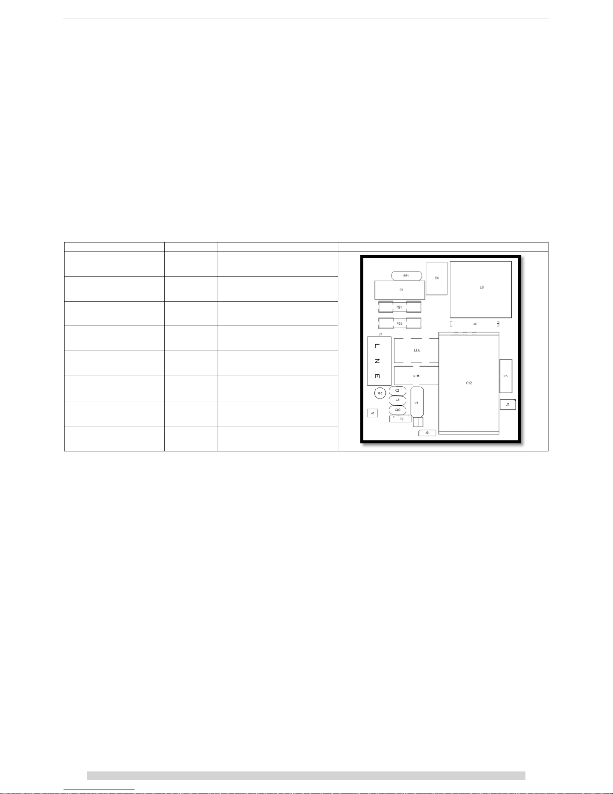
If a cover is placed over the primary components, then the following component temperatures must also be measured to ensure they are below the maximum
specified temperatures.
Description
Reference
Maximum allowed temperature
Drawing
Fuse FS1, FS2
125°C
Electrolytic capacitors C12
105°C
Inductors L1, L2, L3, L5
130°C
Other capacitors C1, C4
110°C
If excessive temperatures are measured during this evaluation, then one or more of the following remedies may improve thermal performance.
• Increase heatsink size
• Increase airflow rate
• Improve air intake & outlet
• Reduce power requirement
Using the internal temperature sensor to control external application cooling
An internal temperature sensor T
SNS
is available on J3 pin 9 (See page 14 for details). The output voltage of this sensor gives a measurement of the internal
transformer temperature and can be used to control external cooling systems or to provide a warning of impending over temperature protection.
The internal temperature (T
SNS
) should never exceed 120⁰C (2.74V), however, system reliability will be maximised if the PSU temperature is maintained as low as
possible in any given application.
 Loading...