

Vox Power NEVO Plus 1200 Series, NEVO Plus 1200S, NEVO Plus 1200M User Manual

NEVO+1200 Series
AC/DC MODULAR CONFIGURABLE POWER SUPPLIES
User Manual
Page 1 of 40
DOC-MN-006-03, NEVO+1200 User Manual
Vox Power Limited | Unit 2, Red Cow Interchange Estate, Ballymount, Dublin 22, D22 Y8H2, Ireland | T +353 1 4591161 | www.vox-power.com
The ultimate 1200 Watt solution
6”x6”x1.61”
SMALL
1200W
POWERFUL
1.2kg
LIGHT
The NEVO+1200 series user manual has been prepared by the Vox Power design team to assist qualified
engineers in correctly implementing the product and to achieve the best reliability and performance possible.
All specifications are believed to be correct at time of publishing. Vox Power Ltd reserves the right to make changes to any of its products and to change or improve any part of the
specification, electrical or mechanical design or manufacturing process without notice. Vox Power Ltd does not assume any liability arising out of the use or application of any of its
products and of any information to the maximum extent permitted by law. No license, express or implied, by estoppel or otherwise, to any intellectual property rights is granted by this
document or by any products of Vox Power Ltd. VOX POWER LTD DISCLAIMS ALL WARRANTIES AND REPRESENTATIONS OF ANY KIND WHETHER EXPRESS OR IMPLIED, INCLUDING,
BUT NOT LIMITED TO, IMPLIED WARRANTIES OF SUITABILITY, FITNESS FOR PURPOSE, MERCHANTABILITY AND NONINFRINGEMENT.
Please consult your local distributor or Vox Power directly to ensure that you have the latest revision before using the product and refer to the latest relevant user manual for further
information relating to the use of the product. Vox Power Ltd products are not intended for use in connection with life support systems, human implantations, nuclear facilities or systems,
aircraft, spacecraft, military or naval missile, ground support or control equipme nt used for the purpose of guidance navigation or direction of any aircraft, spacecraft or military or naval
missile or any other application where product failure could lead to loss of life or catastrophic property damage. The user will hold Vox Power Ltd harmless from any loss, cost or damage
resulting from its breach of these provisions.
NEVO+1200 Series Overview
The Nevo+1200 switch mode power supply series offers truly unrivalled power density, providing 1200W at 22W/inP
3
P in a 6”x6”x1U package. It is the ultimate
power solution for system designers as they address the demand for more power in less space. Providing multiple isolated outputs, the series carry full UL60601
ED3 (NEVO+1200M) and UL60950ED2 safety approvals.
A standard Nevo+1200 product configuration consists of an input module together with up to eight fully isolated output modules. Single output modules have
advanced remote voltage and current programming functionality as standard. While dual output modules allow for up to sixteen fully isolated outputs.
The input module delivers up to 1200W of output power and has 8 slots, each capable of delivering up to 150W. Two 5V, 1A medically isolated bias supplies, an
AC_OK signal and a global inhibit signal that can disable all outputs simultaneously are standard features of a NEVO configuration. An additional (always on) 5V,
0.5A bias supply is provided which enables a fully latched shutdown feature to be implemented on the primary power converter. In this mode both fans are off
and the power consumption is below 5Watts (Typical Value of 3 Watts).
Output modules are available in a range of output voltages to suit all applications. Single output modules with voltage ranges from 1.5V to 60V, currents up to
25A and paralleling and series capability can result in a voltage range up to 480V and a maximum current of up to 200 Amps from a single Nevo+1200
configuration. Dual output modules have a voltage ranges from 1.5V to 15V and currents up to 5A with series capability.
By selecting the correct output modules, a custom power solution can be configured in a few minutes. This fast custom solution offers industry leading power
density and total system efficiencies of up to 89%. This flexibility ensures the Nevo+1200 series suits all types of applications including medical, industrial, lighting,
aerospace, military and telecoms.

NEVO+1200 Series
AC/DC MODULAR CONFIGURABLE POWER SUPPLIES
User Manual
Page 2 of 40
DOC-MN-006-03, NEVO+1200 User Manual
Vox Power Limited | Unit 2, Red Cow Interchange Estate, Ballymount, Dublin 22, D22 Y8H2, Ireland | T +353 1 4591161 | www.vox-power.com
Contents
NEVO+1200 Series Overview ...................................................................................... 1
Part Numbers and Ordering Information ........................................................................ 3
Installation Notes ................................................................................................... 4
Theory of Operation ............................................................................................... 6
Input Module Operation ........................................................................................... 7
Signalling .......................................................................................................... 10
Single Output module operation ............................................................................... 13
Advanced Single Output Module Features..................................................................... 16
Series Connected Modules ...................................................................................... 19
Paralleled Outputs ................................................................................................ 20
Dual Output module operation ................................................................................. 24
Audible Noise ..................................................................................................... 27
Mechanical Dimensions and Mounting ......................................................................... 29
Connectors ........................................................................................................ 30
Configuring Your NEVO Product ............................................................................... 31
Safety .............................................................................................................. 38
EMC Compliance ................................................................................................. 39
Reliability .......................................................................................................... 40
NEVO+1200 Series
AC/DC MODULAR CONFIGURABLE POWER SUPPLIES
User Manual
Page 3 of 40
DOC-MN-006-03, NEVO+1200 User Manual
Vox Power Limited | Unit 2, Red Cow Interchange Estate, Ballymount, Dublin 22, D22 Y8H2, Ireland | T +353 1 4591161 | www.vox-power.com
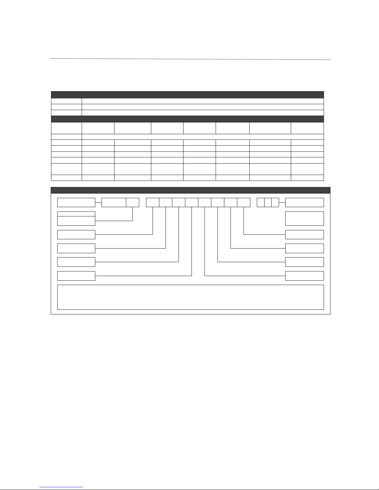
Part Numbers and Ordering Information
INPUT MODULES
Input Module
Details
Nevo+1200S
1200 Watt Input Module with ITE Approvals (EN60950 Edition 2)
Nevo+1200M
1200 Watt Input Module with Medical Approvals EN60601 Edition 3)
OUTPUT MODULES
Module
Nominal voltage
Rated current
Rated Power
Adjustment
range
Load regulation
Line regulation
OVP
0
Unused slots
1
5V
25A
125W
1.5V-7.5V
±50mV
±0.1%Vnom
9V 2 12V
15A
150W
3V-15V
±100mV
±0.1%Vnom
18V 3 24V
7.5A
150W
9V-30V
±150mV
±0.1%Vnom
36V
4
48V
3.75A
150W
18V-58V
±300mV
±0.1%Vnom
66V
5
12V Dual
5A
75W x 2
3.3V-15V Each
Ch
±50mV
±0.1%Vnom
22V
8
24V Dual
3.125A
75W x 2
24V Each Ch
±100mV
±0.1%Vnom
30V
PART NUMBERING SYSTEM
NEVO Input Module
NEVO+1200
S - 1 1 2 2 3 3 4 4 - 0 0
0
Factory Configuration
Number
Product Type
USE '0' for unused slots.
Blanking plates will be
inserted at factory.
S - Standard
M - Medical
Slot A - Output #
Slot H - Output #
Slot B - Output #
Slot G - Output #
Slot C - Output #
Slot F - Output #
Slot D - Output #
Slot E - Output #
Our design team will assist with value add requirement if an application requires standard/non-standard accessories or non-nominal voltage settings.
Once approved, the factory will issue a 3 or 4 digit code for your specific configuration which can be used for all future orders of the same
configuration. When ordering an input unit with no outputs inserted, simply order NEVO+1200S

NEVO+1200 Series
AC/DC MODULAR CONFIGURABLE POWER SUPPLIES
User Manual
Page 4 of 40
DOC-MN-006-03, NEVO+1200 User Manual
Vox Power Limited | Unit 2, Red Cow Interchange Estate, Ballymount, Dublin 22, D22 Y8H2, Ireland | T +353 1 4591161 | www.vox-power.com
Installation Notes
This Nevo+1200 series of configurable power supplies are intended for use within end customer applications which restrict access to un-authorized personnel.
The instructions in this manual and all warning labels on the product must be adhered to carefully.
SAFETY
The NEVO+1200S and Nevo+1200M series are designed in accordance with the safety requirements of UL60950-1, EN60950-1, IEC60950-1, UL60601-1, EN606011, EN61010-1, IEC60601-1, IEC61010-1, CSA22.2 no 601-1 and the LV Directive 2014/35/EU.
All Nevo+1200 series power supplies must be installed correctly in a controlled environment which restricts access to any un-authorised personnel. Equipment
and system manufacturers must protect service personnel against unintentional contact with the output terminals.
DE-RATING
Temperature - The input module and output module power must be de-rated by 2.5%/°C above 50°C.
Input Voltage -The input module power must be de-rated by 10W/Vrms below120Vrms (1200W @ 120Vrms, 1000W @ 100Vrms, 900W @ 90Vrms)
Remember to take the appropriate de-rating into consideration before specifying any Nevo+1200 power supply for an application. If in any doubt please contact
Vox Power directly or your local Vox Power representative.
HAZZARDS
If series and/or parallel combinations of outputs exceed safe voltage and/or energy levels, the final equipment manufacturer must provide the appropriate
protection for both users and service personnel.
HEALTH AND SAFETY
To comply with section 6 of the health and safety at work act, a label that is clearly visible to service personnel must be placed on the final equipment. These
labels warn that surfaces of the power supply may be hot and should not be touched when the product is operating.
FUSING
The power supply has internal single pole fusing in the L (Live) line.
SERVICING
The power supply contains no user serviceable parts. Repairs must be carried out by authorised personnel only. Contact Vox Power for further information.
APPROVAL LIMITATIONS – NORTH AMERICA
When this product is used with 180VAC–253VAC mains where no neutral is present, connect the two live wires to L (Live) and N (Neutral) on the input connector.
COOLING
For proper cooling of the power supply, the air intake and outlet must not be impeded. Allow 50mm clearance at both ends and position cabling appropriately.
EARTH TERMINAL MARKING
To comply with the requirements of UL60950-1, EN60950-1, IEC60950-1, CSA22.2 no. 60950-1, UL60601-1, EN60601-1, EN61010-1, IEC60601-1, IEC61010-1, CSA22.2
no 601-1 where the incoming wiring earth is intended for connection as the main protective earth conductor and where the terminals for such a connection is not
supplied on a component or subassembly , the user shall add an appropriate label displaying a protective earth symbol in accordance with 60417-2-IEC-5019
directly adjacent to the terminal. The label should be durable and legible and should withstand the 15s rub test as per UL60950-1 section 1.7.15.
WARRANTY
Contact your sales agent or Vox Power for product repairs. See Vox Power standard terms and conditions for warranty conditions. Vox Power products are not
intended for use in connection with life support systems, human implantations, nuclear facilities or systems, aircraft, spacecraft, military or naval missile, ground
support or control equipment used for the purpose of guidance navigation or direction of any aircraft, spacecraft or military or naval missile or any other
application where product failure could lead to loss of life or catastrophic property damage. The user will hold Vox Power harmless from any loss, cost or
damage resulting from its breach of these provisions.
PRODUCT LABELS
The external product label contains information relevant to the power system. The label contains input voltage, maximum input current, input frequency,
maximum output power, fuse rating and type, serial number, approvals and product part number in format NEVO+1200X-ABCDEFGH-ZZZ.
NEVO OUTPUT MODULES
Each output module label contains information relevant to that particular output. The label contains voltage adjustment range, maximum output current, serial
number, approvals and the part number in format OP X.

NEVO+1200 Series
AC/DC MODULAR CONFIGURABLE POWER SUPPLIES
User Manual
Page 5 of 40
DOC-MN-006-03, NEVO+1200 User Manual
Vox Power Limited | Unit 2, Red Cow Interchange Estate, Ballymount, Dublin 22, D22 Y8H2, Ireland | T +353 1 4591161 | www.vox-power.com
OTHER
• A label warning that external surfaces are hot during operation and that the unit should be allowed to cool down properly should be placed on the
unit where such a label is clearly visible.
• The NEVO+1200 seriesis designed to comply with EMC standards but it does not imply that the end system will comply.
• To prolong the life of the unit use in dust free environment.
• Units can sometimes be damaged during transit. In the event of transit damage, DO NOT connect power to the unit. Contact your sales agent or Vox
Power.
• Always use adequately sized cables and ensure good crimp connections. Use cable supports to minimise stress on connectors.
• Avoid excessive shock or vibration.
General installation parameters
• Equipment class I
• Installation category II
• Pollution degree 2
• Material group IIIb (Indoor use only)
• Flammability rating 94V-2
• IP rating IP10
• RoHS compliance 2011/65/EU
NEVO+1200 Series
AC/DC MODULAR CONFIGURABLE POWER SUPPLIES
User Manual
Page 6 of 40
DOC-MN-006-03, NEVO+1200 User Manual
Vox Power Limited | Unit 2, Red Cow Interchange Estate, Ballymount, Dublin 22, D22 Y8H2, Ireland | T +353 1 4591161 | www.vox-power.com
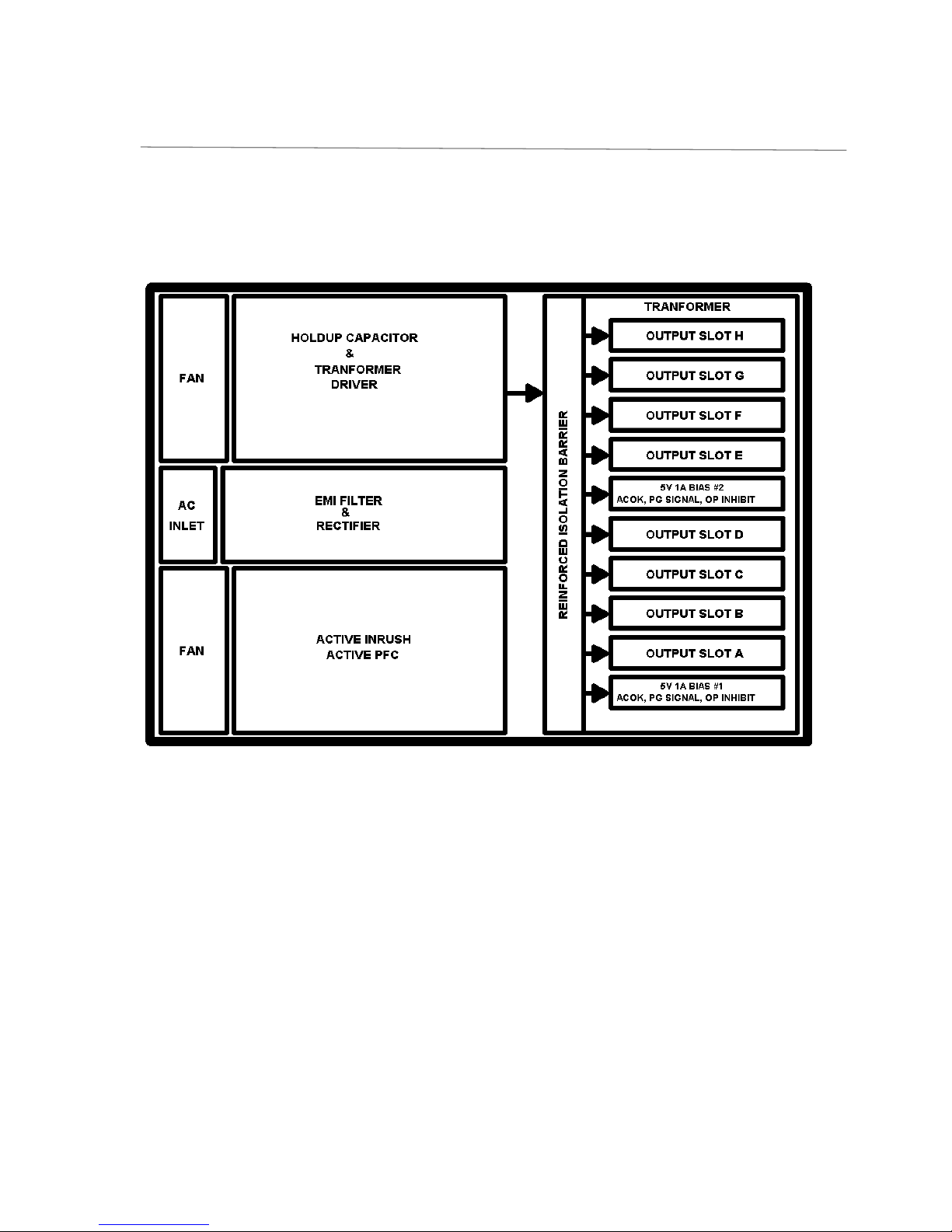
Theory of Operation
The diagram below outlines the topology and major internal components of a fully assembled Nevo+1200 configuration. Eight output slots are provided
and can be populated by any combination of output modules. The remaining components in the block diagram are housed in the input module.
The input module is responsible for receiving the AC mains line voltage and converting it to an appropriate DC voltage whilst providing protection from
AC line disturbances and preventing excessive EMI emissions and current harmonics. The integrated EMI filter attenuates high frequency current emissions
to levels below EN55022 class B. It also provides single pole fusing in the live conductor and protection from line disturbances as outlined in EN61000.
Inrush current is controlled by a resistive element upon initial connection to the AC line. Once the internal capacitances have been charged, the resistive
element is bypassed to reduce losses.
Active Power Factor Correction (PFC) is used to ensure an accurate input current waveform with extremely low harmonic content, exceeding the
requirements of EN61000. This stage also provides active input current limiting which prevents overloading of the input stage while maintaining high
power factor.
The output of the PFC stage charges the hold-up electrolytic capacitors which store enough energy to allow the Nevo+1200 configuration to continue
operating during minor line disturbances. These are the only electrolytic capacitors in the Nevo+1200S/M power supplies. Long lifetime and high
temperature capacitors are used which ensures extended lifetime and product reliability.
A highly efficient zero voltage switching circuit is used to drive the isolated transformer from the hold-up capacitors. The output modules connect to the
transformer secondary and provide safe isolated power to a high performance synchronous rectifier power converter. This power converter is controlled
using the latest analog control technology to produce superior output performance in a miniature size.
NEVO+1200 Series
AC/DC MODULAR CONFIGURABLE POWER SUPPLIES
User Manual
Page 7 of 40
DOC-MN-006-03, NEVO+1200 User Manual
Vox Power Limited | Unit 2, Red Cow Interchange Estate, Ballymount, Dublin 22, D22 Y8H2, Ireland | T +353 1 4591161 | www.vox-power.com
Input Module Operation
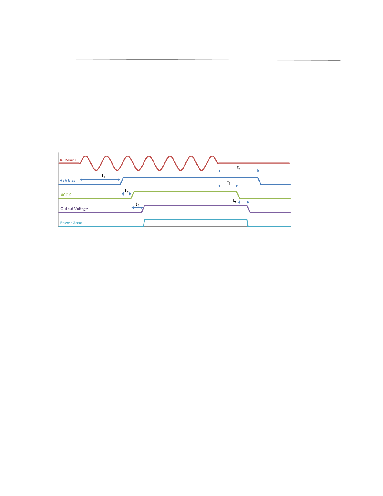
Startup &Shut Down
The NEVO input module operates from a universal input voltage range and starts automatically upon application of adequate AC mains voltage
(>84Vrms). After a short delay, the global 5V bias supplies start and the ACOK signal goes high to indicate that the mains voltage is present and input
stage is operating correctly. Once the ACOK signal is high, the output modules turn on and deliver power to the application loads. The power good
signals will indicate that the output voltages are within specification. The diagram below shows the normal start up/shut down sequence and gives typical
timings.
Typical timing values at 25˚C: tR
1
R 2000 ms, t
2
50 ms, t325 ms, t4 15 ms, t
5
= 5 ms (minimum), t
6
100 ms
When the AC mains voltage is removed, the internal hold-up capacitors will supply power to the load for typically 20 ms (t4+t5) at maximum power. The
ACOK signal will go low at least 5ms before the output voltages fall below the power good threshold level. This allows the application to prepare for the
impending loss of power. The 5V bias supply will remain on for typically 80ms, after the output modules have turned off.
Hold-up
For short line distubances (<20ms), the output voltages will not be affected*. However, the ACOK signal may still go low to warn that there is an
impending loss of output power. The ACOK signal will return to the high state once the unit has recovered from the disturbance.
*Outputs that are adjusted above the hold-up voltage as detailed in their respective datasheets, may experience a dip in voltage but never below the
hold-up voltage specified.
Idle power/Standby Power Consumption
The idle power of the NEVO+1200 series PSU is extremely low when compared to similar configurable power supplies.
With the output modules enabled the unit typically only requires 46 W with no output load. To reduce the idle power further the outputs can be disabled
using the global inhibit (GINH) pins. With the outputs disabled the unit typically requires less than 36 W. When the unit is in the latched off (SHUTDOWN)
state, the idle power is less than 5W (Typical Value 3W)
Over Temperature Protection (OTP)
The input module is protected from excessive temperatures by means of various internal sensors. If temperature thresholds are exceeded the entire unit
may latch off, with no ACOK warning. To re-enable the unit the AC mains must be disconnected for approximately 20seconds.
Over Power Protection (OPP)
The input module is protected from excessive power by means of a hiccup mode over power protection circuit. The threshold for the protection is
approximately 120% of the rated power. If this threshold is exceeded the unit will shutdown for a short period before recovering automatically. If the
overload remains this process will repeat indefinitely.
NEVO+1200 Series
AC/DC MODULAR CONFIGURABLE POWER SUPPLIES
User Manual
Page 8 of 40
DOC-MN-006-03, NEVO+1200 User Manual
Vox Power Limited | Unit 2, Red Cow Interchange Estate, Ballymount, Dublin 22, D22 Y8H2, Ireland | T +353 1 4591161 | www.vox-power.com
0
200
400
600
800
1000
1200
1400
80 100 120 140 160 180 200 220 240 260
Output Power (W)
Input Voltage (RMS)
Line Derating
Derate at 10W per Volt below 120Vrms
No Derating for DC operation
0
200
400
600
800
1000
1200
1400
-20 -10 0 10 20 30 40 50 60 70
Output Power (W)
Ambient Temperature (Celcius)
Temperature Derating
Derate at 30W per degreecelcius above 50 degree celcius
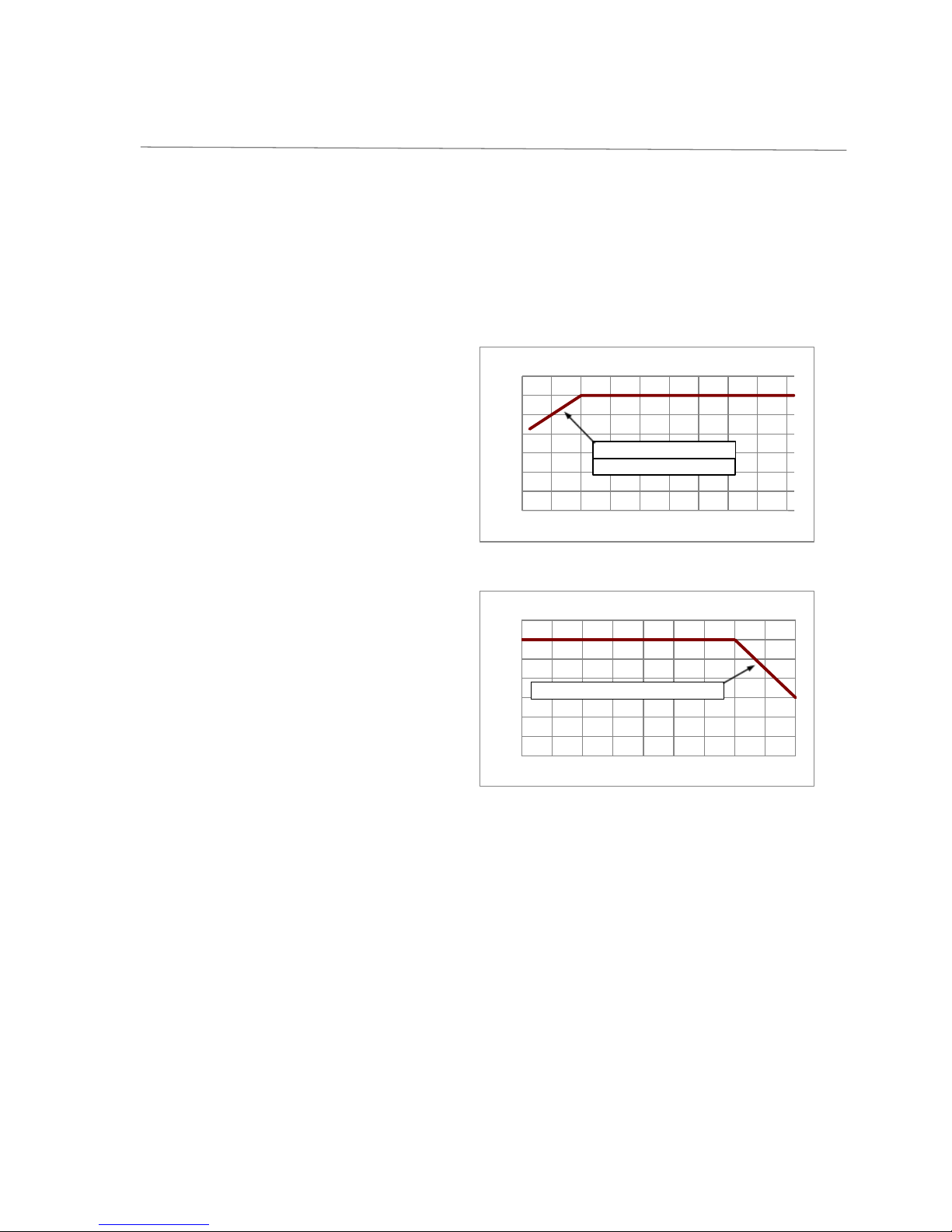
Power De-Rating
The NEVO+1200 series must always be operated within its stated operating limits. Equipment manufacturers and other users must take the appropriate
de-rating into account when specifying a unit for the intended application. If in doubt contact your sales representative or Vox Power for assistance.
There are two main de-ratings for the NEVO+1200 series configurable power supplies i.e. temperature and input line voltage. Temperature de-ratings
apply to both input and output modules, while line de-ratings apply only to the input module.
For temperature, the de-rating for both input and output modules is 2.5% (of maximum rated power) per degree Celsius above 50°C. For the input line
voltage, the de-rating for the input module only is 10W per volt below 120Vrms. These de-ratings can be calculated using the following conditional
equations;
Equation for line de-rating
of input module only:
If Vin< 120V,
Pout = Prated-(10W*(120V-Vin))
Otherwise,
Pout = Prated
Equation for temperature de-rating
of the input and output modules:
If temp > 50˚C,
Pout = Prated-[(Temp-50˚C)*(0.025*Prated)]
Otherwise,
Pout = Prated
Depending on the application conditions, one or both of the de-ratings may apply. Where both apply, calculate each de-rating in turn and fill the result
from the first calculation into the second calculation.
Example: What are the NEVO+1200 input and output module de-ratings at 60°C at 100V line?
Input module line de-rating
= Prated-(10W*(120V-Vin)) = 1200W-(10W*(120V-100V) = 1000W
Input module temperature & line de-rating
= Prated-[(Temp-50˚C)*(0.025*Prated)] = 1000W-[(60˚C -50˚C)*(0.025*1000W)] = 750W
150W Output module temperature de-rating
= Prated-[(Temp-50˚C)*(0.025*Prated)] = 150W-[(60˚C -50˚C)*(0.025*150W) = 112.5W
NEVO+1200 Series
AC/DC MODULAR CONFIGURABLE POWER SUPPLIES
User Manual
Page 9 of 40
DOC-MN-006-03, NEVO+1200 User Manual
Vox Power Limited | Unit 2, Red Cow Interchange Estate, Ballymount, Dublin 22, D22 Y8H2, Ireland | T +353 1 4591161 | www.vox-power.com
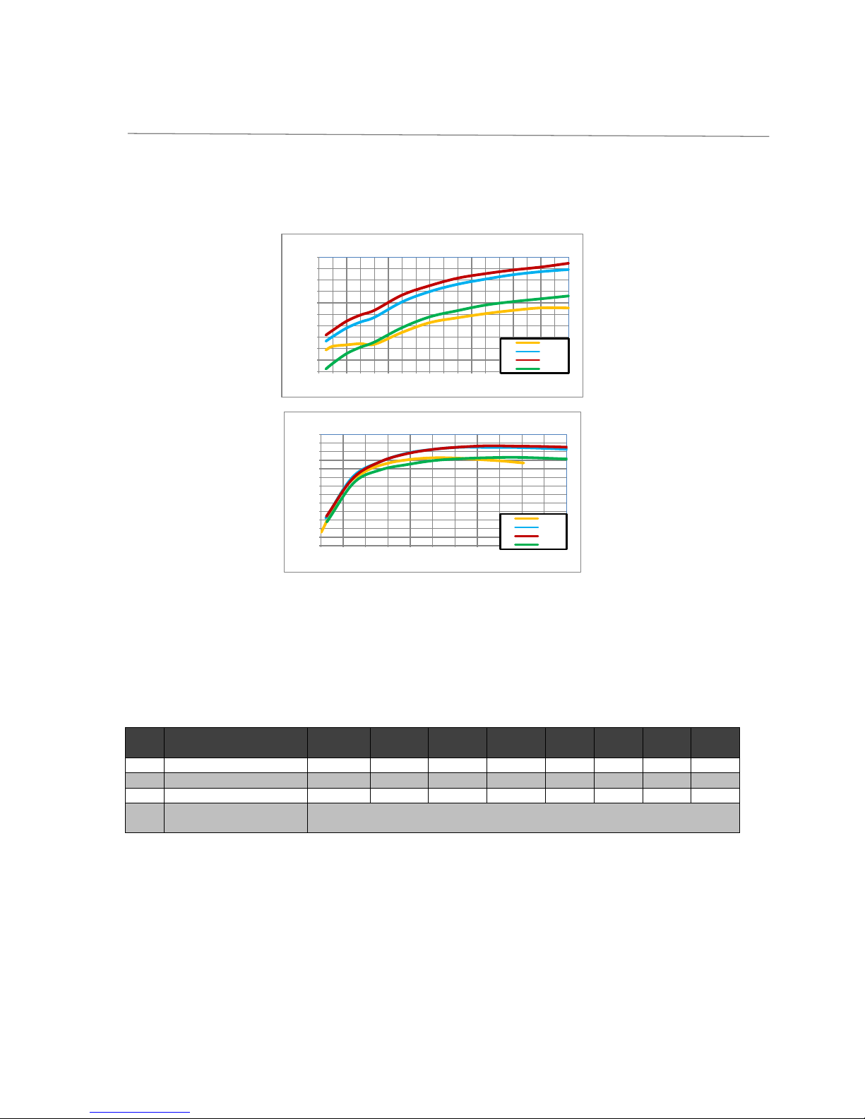
Efficiency
The efficiency of the configured Nevo+1200 product is dependent on parameters such as input line voltage, load level and on the combination of output
modules. The plots below show typical efficiencies of a NEVO+1200 over the full load and line voltage range and fitted with four of each type of single
output module, equally loaded.
An estimate of the efficiency for any particular system may be obtained from these graphs using the procedure outlined in the example below.
Example: Estimate the efficiency of an NEVO+1200-11223344, at 160Vrms input and 100W load on each output?
1. Define load efficiencies for each output module at the specified load and 220V.
2. Define change in efficiency from 220Vrms to 160Vrms for each output module.
3. Sum the values from step one and two for each output module.
4. Calculate the average efficiency for the total system.
Step
Details
Slot A
OP1
Slot B
OP1
Slot C
OP2
Slot D
OP2
Slot E
OP3
Slot F
OP3
Slot G
OP4
Slot H
OP4 1 Є
220
(Load chart)
0.86
0.86
0.89
0.89
0.895
0.895
0.86
0.86 2 ∆Є
(220-160)
(Line chart)
-0.01
-0.01
-0.015
-0.015
-0.015
-0.015
-0.01
-0.01 3 Єx = Є
220
+ ∆Є
(220-160)
0.85
0.85
0.875
0.875
0.88
0.88
0.85
0.85
4
Є
AVE
= (Є1+Є2+Є3+Є4+
Є5+Є6+Є7+Є8)/8
0.86375
0.80
0.81
0.82
0.83
0.84
0.85
0.86
0.87
0.88
0.89
0.90
80 90 100 110 120 130 140 150 160 170 180 190 200 210 220 230 240 250 260
Efficiency
Input Voltage(Vrms)
Typical Line Efficiency (Pmax)
OP1
OP2
OP3
OP4
0.66
0.68
0.70
0.72
0.74
0.76
0.78
0.80
0.82
0.84
0.86
0.88
0.90
0.92
100 200 300 400 500 600 700 800 900 1000 1100 1200
Efficiency
Output power (W)
Typical Load Efficiency (220Vrms)
OP1
OP2
OP3
OP4

NEVO+1200 Series
AC/DC MODULAR CONFIGURABLE POWER SUPPLIES
User Manual
Page 10 of 40
DOC-MN-006-03, NEVO+1200 User Manual
Vox Power Limited | Unit 2, Red Cow Interchange Estate, Ballymount, Dublin 22, D22 Y8H2, Ireland | T +353 1 4591161 | www.vox-power.com
Signalling
Output Signals
The NEVO+1200 has two isolated output signalling sections arranged in groups, the first covers slots A to D and the second covers slots E to F. To reduce
cabling in the end system, all major input and output signals and the global 5V bias supply for each group are wired to a single signals circuit that is
accessed through the connectors (J2a and J2b) located at the output side of the chassis as shown in the diagram below.
J2a
J2b
Pin
Name
Description
Pin
Name
Description
1
PG1
Power Good
Slot A
1
PG5
Power Good
Slot E
2
INH1
Inhibit 2 INH5
Inhibit 3 PG2
Power Good
Slot B
3
PG6
Power Good
Slot F
4
INH2
Inhibit 4 INH6
Inhibit
5
PG3
Power Good
Slot C
5
PG7
Power Good
Slot G
6
INH3
Inhibit 6 INH7
Inhibit 7 PG4
Power Good
Slot D
7
PG8
Power Good
Slot H
8
INH4
Inhibit 8 INH8
Inhibit
9
GINH1
Group 1 inhibit
Slot A-D
9
GINH2
Group 2 inhibit
Slot E-F
10
ACOK1
AC mains signal
10
ACOK2
AC mains signal
11
+5V1
Global 5V Bias
11
+5V2
Global 5V Bias
12
COM1
Common
12
COM2
Common
All of the signals are referenced to the relevant group bias supply common rail (COM) and external control and/or monitoring circuits can be easily
powered and interfaced to the PSU through these connectors. Both entire signals circuits are fully medically isolated and can be considered a SELV
output. The table below lists the isolation voltages.
Signals isolation voltages
Signals to Input
4000
Vac
Signals to Chassis
250
Vdc
Signals to Output
250
Vdc
Bias supplies (+5V1 & +5V2 [Power])
The NEVO+1200 series has three separate isolated bias supplies, one (J6) located near the AC mains input connector (J1) and two more located at the
output side connectors (J2a & J2b).
Both output side bias supplies generate 5V and are rated up to 1A. These supplies are available whenever the AC mains voltage is connected and the
input module is operating correctly. A shutdown through the SD pin on J6 or any of the following abnormal conditions will cause the entire unit to latch
off and will disable both of these 5V bias supplies:
• Over temperature of any part of the unit
• Over voltage on the output
• Internal over current (device failure)
NEVO+1200 Series
AC/DC MODULAR CONFIGURABLE POWER SUPPLIES
User Manual
Page 11 of 40
DOC-MN-006-03, NEVO+1200 User Manual
Vox Power Limited | Unit 2, Red Cow Interchange Estate, Ballymount, Dublin 22, D22 Y8H2, Ireland | T +353 1 4591161 | www.vox-power.com
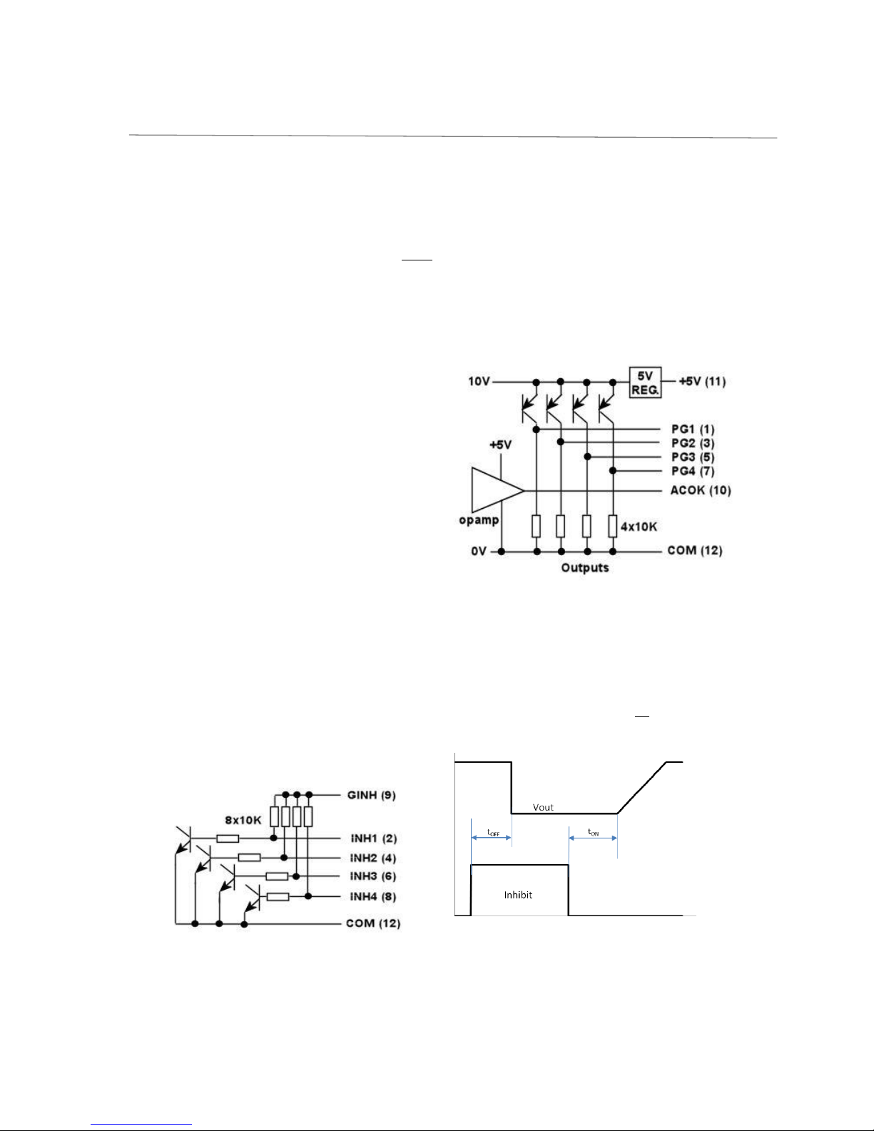
AC Mains Signal (ACOK [Output])
An ACOK signal is provided on each output group to indicate to the user that the AC mains voltage is applied and the input module is operating
correctly. The output signal is driven from an internal operational amplifier as shown in the following diagram. Under normal operating conditions this
signal gives a warning of 5ms before the output voltage falls below the power good threshold. A shutdown through the SD pin on J6 or any of the
following abnormal conditions may cause the entire unit to latch off UwithoutU the minimum 5mS ACOK warning:
• Over temperature of any part of the unit
• Over voltage on the output
• Internal over current (device failure)
Power Good Signals (PG1-PG4& PG5-PG8 [Output])
Each output module provides a power good (PG) signal to indicate when
the output voltage is above approximately 90% of the pre-set voltage for
that module. Each PG signal on an output module is internally connected
through an opto-isolator to the group signals circuit, which buffers the
signal through a PNP transistor with a 10k pull down resistor, as shown.
The LED on the front of each module gives a visual confirmation of the PG
status.
Note that remote adjustments of the output voltage using the Vcontrol and
Icontrol pins do not change the PG signal threshold. The PG threshold is
always approximately 90% of the voltage set with the manual
potentiometer.
Output Inhibits (INH1-INH4& INH5-INH8, GINH1 & GINH2 [Input])
The signals circuit provides an inhibit input to disable each output module individually and global inhibit inputs (GINH1 & GINH2) to inhibit each group of
modules simultaneously. Each inhibit input is internally connected through an opto-isolator to the respective output modules. The basic internal electrical
circuit and timing diagrams are shown below.
Typically, t
OFF
= 100 μs and tON = 8 ms.
To inhibit each output module individually, GINH for the relevant group should be connected to COM, and 5V applied to the appropriate input
INH1/2/3/4/5/6/7/8. To start with all outputs inhibited and then enable them individually, GINH should be connected to +5V, then pull down the
appropriate input INH1/2/3/4. If GINH is left unconnected, then all INH inputs will all behave as global inhibit inputs. i.e. 5V on UanyU INH input will disable
all outputs in that group.
NEVO+1200 Series
AC/DC MODULAR CONFIGURABLE POWER SUPPLIES
User Manual
Page 12 of 40
DOC-MN-006-03, NEVO+1200 User Manual
Vox Power Limited | Unit 2, Red Cow Interchange Estate, Ballymount, Dublin 22, D22 Y8H2, Ireland | T +353 1 4591161 | www.vox-power.com
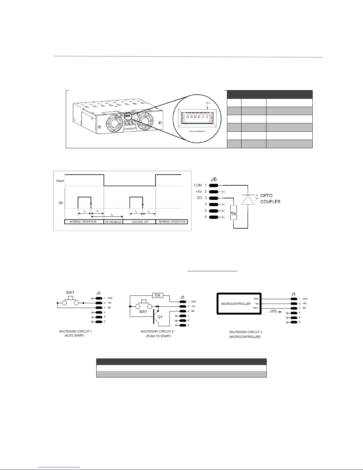
Input Signals
The input side signals are located on J6 near the AC mains input connecter. The signals consist of a 5V bias supply and a shutdown pin (SD).The input bias
supply generates 5V, is rated up to 0.5A and is "Always on" when the AC mains is connected regardless of whether the PSU has been shutdown.
The sequence to shutdown and restart the PSU is shown in the timing diagram below.
t1>= 5mS, t2<= 25mS, t3>= 200mS, t4>= 500mS, t5<= 600mS Internal circuit
The SD pin is negative edge triggered. To shut down the PSU during normal operation, 5V must be applied for a minimum of t1 then released. After a
period of t2 the main outputs will shut down but the bias voltages 5V1 and 5V2 will remain on. If the SD pin remains low for a period of t3 the PSU will shut
down and stay latched in that state. If the SD does not remain low for a period of t3 then the outputs will turn on again. When in the latched state, the PSU
will resume normal operation when 5V is applied to the SD pin for a period of t
4
Uand released for a period of t5U.
This operation is perfect for push button or microcontroller on/off control using the recommended circuits below.
All pins on the J6 connector are isolated to the following specification.
J6 Signals isolation voltages
Signals to Input
4000
Vac
Signals to Chassis
250
Vdc
Pin
Name
Description
1
COM
Common
2
+5V
"Always on" 5V Bias
3
SD
Shutdown
4
Reserved
5
Reserved
6
Reserved
 Loading...