

Page 1
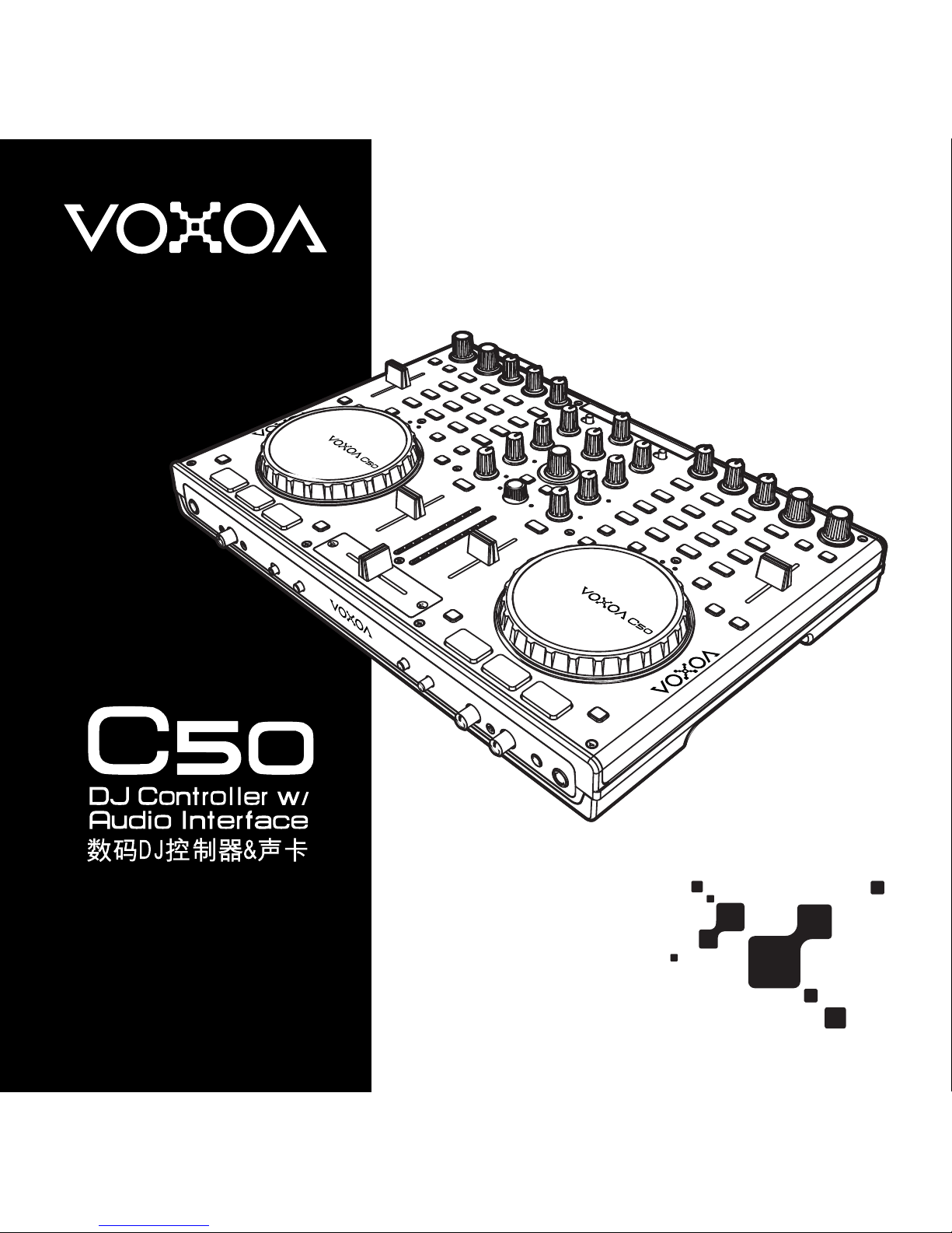
User Manual
使 用 說 明 書
Page 2

3
Co nte nts
ENGL I SH
IMPO RTANT SA FETY I NSTRUCT IONS
.... . ........ ........ . ........ ........ . ........ ......... ........ ......... 30
FEATU R ES
... ......... . ......... ......... . ......... ......... . ......... ......... . ......... ......... . ......... ......... . . 3 2
SOFTWARE INS TA L LATION INS T RUCTION ..... ......... . ......... ......... . ......... ......... . ......... .. 34
INS TA LLING ASIO DRIVE R for WIND O WS
......... ......... . ......... ......... . ......... ......... . ......... . . 34
INS TA LLING VIRTU ALDJ for W I NDOWS
... ......... . ......... ......... . ......... ......... . ......... ......... . . 35
INS TA LLING VIRTU ALDJ for M A C OS
..... ......... . ......... ......... . ......... ......... . ......... ......... . .. 36
SETU P AND F IRMWA RE UPDAT E
...... . ......... ......... . ......... ......... . ......... ......... . ......... ...... 37
SET TING S OFTWARE
... ......... . ......... ......... . ......... ......... . ......... ......... . ......... ......... . ..... 37
FIR MWARE UPDAT E
........ . ......... ......... . ......... ......... . ......... ......... . ......... ......... . ......... . 38
CHA NGING SETTI NGS T H ROUGH CON TROLL E R
. ......... ......... . ......... ......... . ......... . ........ 38
AUDI O SETUP
........ ......... . ......... ......... . ......... ......... . ......... ......... . ......... ......... . ......... . 40
AUD IO INT ERFACE SETUP FOR V IRTUAL DJ
........ ......... . ......... ......... . ......... ......... . ........ 40
AUD IO INT ERFACE SETUP FOR T RAKTO R
... . ......... ......... . ......... ......... . ......... ......... . ...... 42
CONN ECTIONS
. ......... . ......... ......... . ......... ......... . ......... ......... . ......... ......... . ......... ...... 43
PART NAMES AND FU NCTION S
... ........ ........ ....... ........ ........ ........ ....... ........ ........ ........ 44
MIX ER SEC TION
...... ......... . ......... ......... . ......... ......... . ......... ......... . ......... ......... . ....... 44
FRONT PANE
L
....... . . . . . .. . .. . .. .. . .. . .. . .. . .. . .. . .. . .. . .. . .. . .. . .. .. . .. . .. . .. . .. . .. . .. . .. . .. . .. . .. . .. . .. .. . . 45
REA R PANEL
..... ......... . ......... ......... . ......... ......... . ......... ......... . ......... ......... . ......... .... 46
SOFT WARE C ONTROL FOR VI R TUALDJ
........ . ........ . ......... . ........ . ......... . ........ . ......... . ... 4 8
FUN CTIONS MAP
..... ......... . ......... ......... . ......... ......... . ......... ......... . ......... ......... . ........ 48
CON TROL A ND FU NCTIO N S
. ......... ......... . ......... ......... . ......... ......... . ......... ......... . ........ 49
MID I MAP( HEX)
..... . ........ . ......... . ......... ......... . ......... ......... . ......... ......... . ......... ......... . . 52
SPEC IFICATIO NS
.... ......... . ......... ......... . ......... ......... . ......... ......... . ......... ......... . ......... . 55
Page 3
30
E N G L I S H
IM POR TAN T S AFE TY INSTR UCT ION S
1. Read these instructions.
2. Keep these instructions.
3. Heed all warnings.
4. Follow all instructions.
5. Do not use the apparatus near water.
6. Clean only with dry cloth.
7. Do not block any ventilation openings. Install in accordance with the manufacturer’s instructions.
8. Do not install near any heat sources such as radiators, heat registers, stoves, or other apparatus (including amplifiers) that
produce heat.
9. Do not defeat the safety purpose of the polarized or grounding-type plug. A polarized plug has two blades with one wider
than the other. A grounding-type plug has two blades and a third grounding prong. The wide blade or the third prong is
provided for your safety. If the provided plug does not fit into your outlet, consult an electrician for replacement of the obsolete
outlet.
10. Protect the power cord from being walked on or pinched particularly at plugs, convenience receptacles, and the point where
they exit from the apparatus.
11. Only use attachments/ accessories specified by the manufacturer.
12. Use only with a cart, stand, tripod, bracket or table specified by the manufacturer, or sold with the apparatus.
When a cart is used, use caution when moving the cart/apparatus combination to avoid injury from tip-over.
13. Unplug this apparatus during lighting storms or when unused for long periods of time.
14. Refer all servicing to qualified service personnel. Servicing is required when the apparatus has been damaged in any
way, such as power-supply cord or plug is damaged, liquid has been spilled or objects have fallen into the apparatus, the
apparatus has been exposed to rain or moisture, does not operate normally, or has been dropped.
15. When the mains plug or appliance coupler used as the disconnect device, it shall remain readily operable.
16. Please keep the unit in a good ventilation environment.
To reduce the risk of fire or electric shock, do not expose this apparatus to rain or moisture. The apparatus shall not be
exposed to dripping or splashing and that no objects filled with liquids, such as vases, shall be placed on the apparatus.
To prevent electric shock, do not use this polarized plug with an extension cord, receptacle or other outlet unless the blades
can be fully inserted to prevent blade exposure.
The lightning flash with arrowhead symbol within the equilateral triangle is intended to alert the use to the presence
of un-insulated “dangerous voltage” within the product’s enclosure that may be of sufficient magnitude to constitute
a risk of electric shock.
CAUTION : To reduce the risk of electric shock, do not remove any cover. No userserviceable parts inside. Refer servicing to qualified service personnel only.
The exclamation point within the equilateral triangle is intended to alert the user to the presence of important
operation and maintenance (servicing) instructions in the literature accompanying this appliance.
WARNING
CAUT I O N
Page 4

31
E N G L I S H
IM POR TAN T S AFE TY INSTR UCT ION S
17. All warnings on the appliance and in the operating instructions should be adhered to.
18. Heat - The appliance should be situated away from heat sources such as radiators, heat registers, stoves, or other appliances
(including amplifiers) that produce heat.
19. Power Sources - This product should be operated only from the type of power source indicated on the rating label. If you
are not sure of the type of power supply to your home, consult your product dealer or local power company. For products
intended to operate from battery power, or other sources, refer the operating instructions.
20. Grounding or Polarization - This product may be equipped with a polarized alternation-current line plug (a plug having one
blade wider than the other). This plug will fit into the power outlet only one way. This is a safety feature. If you are unable to
insert the plug fully into the outlet, try reversing the plug. If the plug should still fail to fit, contact your electrician to replace
your obsolete outlet. Do not defeat the safety purpose of the polarized plug.
21. Power-Cord Protection - Power-supply cords should be routed so that they are not likely to be walked on or pinched by items
placed upon or against them, paying particular attention to the cord in correspondence of plugs, convenience receptacles,
and the point where they exit from the appliance.
22. For AC line powered units - Before returning repaired unit to user, use an ohm-meter to measure from both AC plug blades to
all exposed metallic parts. The resistance should be more than 100,000 ohms.
23. Non-use Periods - The power cord of the appliance should be unplugged from the outlet when left unused for a long period
of time.
24. Object and Liquid Entry - Care should be taken so that objects do not fall and liquids are not spilled into the enclosure
through openings.
25. Damage Requiring Service - The appliance should be serviced by qualified service personnel when:
A. The power-supply cord or the plug has been damaged; or
B. Objects have fallen, or liquid has been spilled into the appliance; or
C. The appliance has been exposed to rain; or
D. The appliance does not appear to operate normally or exhibits a marked change in performance; or
E. The appliance has been dropped, or the enclosure damaged.
26. Servicing - The user should not attempt any service to the appliance beyond that that described in the operating instructions.
All other servicing should be referred to qualified service personnel.
27. Lightning - For added protection for this product during a lightning storm, or when it is left unattended and unused for long
periods of time, unplug it from the wall outlet and disconnect the antenna or cable system. This will prevent damage to the
product due to lightning and power-line surges.
28. Replacement Parts - When replacement parts are required, be sure the service technician has used replacement parts
specified by the manufacturer or have the same characteristics as the original part. Unauthorized substitutions may result in
fire, electric shock, or other hazards.
29. Safety Check - Upon completion of any service or repairs to this product, ask the service technician to perform safety checks
to determine that the product is in proper operating condition.
Page 5

32
E N G L I S H
INTUITIVE LAYOUT AND 4 DECKS CONTROL
Each side of the unit can control up to two decks with visible deck color change for intuitive, straightfoward
operation. Maximum 4 decks control by switching through with the DECK selector.
BUILD-IN SOUND CARD
The VOXOA C50 includes a high quailty 16bit/48kHz, 2in/2Out (Sterro) Audio interface which enables you to input
and output high-quality sound.
Direct Audio THRU
Audio and AUX input and can be directly sent to the master outupt with the THRU (through) switch. In case when
the computer crash you have backup plan for your performance.
TOUCH-SENSITIVE JOG WHEELS
The touch-sensitive Jog Wheels can accurately reproduce hand scratching effects of vinyl records. The Jog Sensor
adjust knobs for speedy and accurate adjustments the C50’s jog wheels have excellent tracking ability, and flexibility
for various DJing sytles.
BUNDLE WITH VIRTUALDJ
It comes bundled with VirtualDJ, Audio/Video/Karaoke mixing software. The C50 is MIDI-mapable and compatible
with other popular DJ programs. The unit interfaces seamlessly with Mac® OSX and Windows XP, Vista and
Windows 7 operating systems.
Dual Headphone Jacks
There are two headphone Jacks 1/8 inch and 1/4 inch connection. That can satisfy different headphones in the
market.
Replaceable Crossfader and Audio/Video Crossfader switchable
Easy replaceable crossfader design and crossfader curve adjustment provide professional different alternative.
Moreover, the crossfader can be switch between Audio/Video crossfader for VIRTUALDJ DJing software.
108 Control Elements
The C50 Included 76 buttons, 5 faders, 19 knobs, 6 Encoders and 2 touch-sensitive jog wheels. The full function
design can satisfy professionals' requirement.
FE ATU RES
Page 6

33
E N G L I S H
•
Inputs: Line/Phone x 2 (RCA), MIC x2 (6.3mm), Aux x1, USB type B x 1
•
Outputs: Master x 2 (balanced and RCA), headphone x 2 (3.5mm and 6.3mm)
•
Build-in sound card
•
Matrix inputs select for diversity inputs
•
Easy replaceable crossfader with curve adjust knob
•
Three-band EQ with Full output kill function for each channel
•
MP3 player and tablet pad friendly Aux input
•
MIC with level control
•
Headphone with level control and cue mixing
•
Dual headphone jack 6.3mm and 3.5mm
•
Dual 10 LED monitor display
•
DVS direct mode for timecode DJing software
•
Bundle with VirtualDJ
•
Bundle with low latency ASIO driver
•
Intuitive layout design and 4 Decks control
•
Touch-sensitive jog wheels
•
Jog wheels sensor adjust knobs for each wheel
•
Durable large-size Cue, PLAY and Cue Play buttons
•
Dual functions cross fader for VirtualDJ (Audio/Video Cross fader)
•
Dual FX units control with 4 knobs and 4 buttons for each unit
•
Independent 8 samples buttons for sample deck or sample bank
•
SHIFT key in two sides for various dual-button operations
•
Function setting software and firmware updatable
•
108 control elements included 76 buttons, 19 knobs, 6 encoders, 5 faders and 2 jog wheels
•
Perfectly control the newest DJing software functions include loop recorder and sample deck
•
Control Video transition and video effect for video DJing software
FE ATU RES
Page 7
34
E N G L I S H
INSTALLING ASIO DRIVER FOR WINDOWS
Before you can use the VOXOA C50, you need to install its ASIO driver first. The ASIO lower latency to under 10
ms. you can configure the driver's settings using the Control Panel window. This tool and its options are explained
following:
PC SYSTEM REQUIREMENTS (Minimum system requirements):
- Intel Pentium II 450MHz CPU or comparable AMD CPU(recommend at least a Pentium III CPU with 600M MHz) .
- Windows 98SE, ME, 2000, XP, Vista and Windows 7 operating system
- 1 available USB port
- At least 128MB RAM
- Software applications with ASIO support
INSTALLATION:
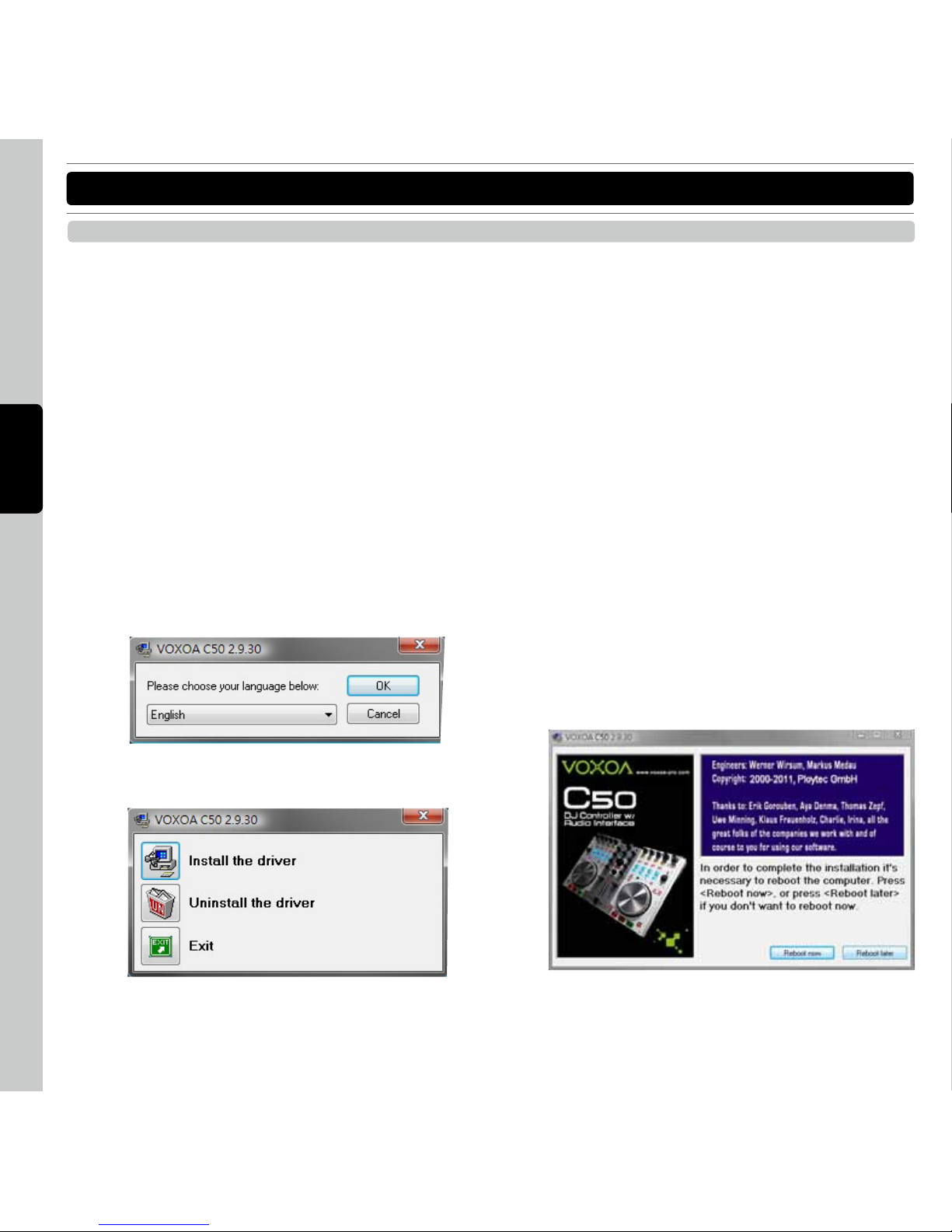
Step 1: Place the installation CD in the CD-ROM drive of your computer and execute Setup.exe file.
SO FTW ARE IN STA LLATION INS TRU CTI ON
Step 2: Select the desired language and click “Ok”
Step 3: Click “Install the driver”
Step 4:
Follow the instructions from the installation windown
and install the driver step bt step.
Step 5:
In order to complete the installation it’s necessary
to reboot the computer. Press [Reboot now], or
press [Reboot later] if you don’t want to reboot
your computer now.
Page 8

35
E N G L I S H
SO FTW ARE IN STA LLATION INS TRU CTI ON
INSTALLING VIRTUALDJ FOR WINDOWS
PC SYSTEM REQUIREMENTS
•
Minimum system requirements:
-Intel® Pentium® 4 or AMD Athlon™ XP
-1024x768 resolution
-DirectX compatible soundcard
-512MB RAM
-50MB free on the hard drive
•
RECOMENDED system requirements:
-Intel® Core™ 2 or AMD Athlon™ X2
-1280x1024 resolution
-Multi-channel DirectX compatible soundcard
-1024MB RAM
-200MB free on the hard drive
•
Additional requirements for video mixing:
-2048MB (2GB) RAM
-ATI™ or NVIDIA® video card w/256MB of Dedicated
DDR3 RAM
-Video card must support dual-screen output
•
Supported Operating System:
-MINIMUM: Microsoft® Windows XP SP3 or newer
- R E C O M M E N D E D : M i c r os of t® W in do ws 7
Professional 32-bit
-Microsoft® Windows 95, 98, ME, or older are not
supported
INSTALLATION:
Use the following steps to install the DJ software
“VirtualDJ” in the supplied CD-ROM.
Step 1: I
nsert the included installer disc to your computer.
Step 2: Double click “install_virtualdj_le.exe” to execute
the installer
Step 3: Follow each step in the installation screen for
installation.
Step 4:
When the installation completes, click the “Finish
”
button to close the installation screen.
Step 5: Double click the VirtualDJ icon created on the
desktop. And then follow the instructions on the
to enter the product serial number.
NOTE
:
The serial number is printed on the back of the CD-
ROM case.
For information about how to use the DJ software, see
the instruction manual for the DJ software or the help
menu. VirtualDJ is an Atomix Productions software. To
install and use the software, you have to accept the
software license agreement. VOXOA Co. shall not be
responsible for any problems with your computer and
other software that may arise from the installation and
use of VirtualDJ.
Page 9
36
E N G L I S H
SO FTW ARE IN STA LLATION INS TRU CTI ON
MAC SYSTEM REQUIREMENTS
•
Minimum system requirements:
-Intel® processor
-Mac OS X v10.5.x
-1024x768 resolution
-CoreAudio compatible soundcard
-1024MB RAM
-50MB free on the hard drive
•
RECOMENDED system requirements:
-Intel® processor
-Mac OS X v10.6.x
-1440x900 resolution
-Multi-channel CoreAudio compatible soundcard
-2048MB (2Gb) RAM
-200MB free on the hard drive
•
Additional requirements for video mixing:
-ATI™ o r NVIDI A ® video chipset w/256MB of
Dedicated DDR3 RAM
-Video must support dual-screen output
•
Supported Operating System and Processor Platforms:
-MIN I MUM: M a c OS X v10 . 5 Lea p ord on Int e l
processor platform
-RECOMMENDED: Mac OS X v10.6.x Snow Leapord
on Intel processor platform
-Apple® Mac OS X 10.4.x Tiger or older are not
supported
-Motorola® (PowerBook® G4) processor platform or
older are not supported.
INSTALLATION:
Step 1: I
nsert the included installer disc to your
computer.
Step 2:Double click “install_virtualdj_le.exe” to execute
the installer
Step 3:Follow each step in the installation screen for
installation.
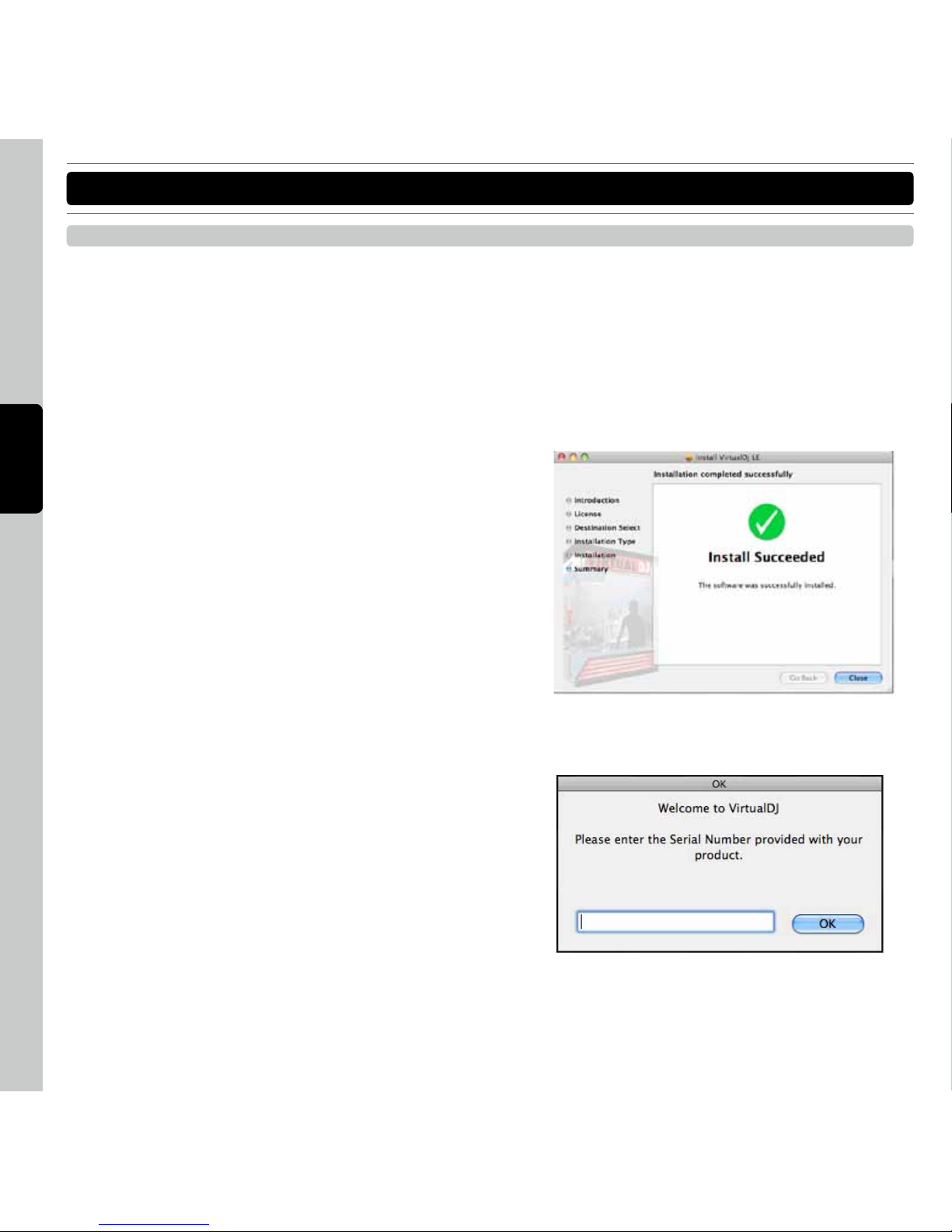
Step 4: When the installation completes, click the
“Close” button to close the installation screen.
Step 5: The Serial Number is required when first starting
VirtualDJ. The serial number for VirtualDJ is
printed on bottom panel of C50.
Note: The serial number is printed on the back of the
CD-ROM case.
INSTALLING VIRTUALDJ FOR MAC OS
Page 10

37
E N G L I S H
SE TUP AN D F IRM WARE UPD ATE
There are two approaches to set the C50. One is setting through VOXOA Settings and Update software. The other is
directly control by the hardware.
INITIALIZE
Initialize the program to get model no. of the device.
CHANNEL
To set the controller’s channels. The default channels are
Channel 1 to Channel 4.
SETTINGS:
Following functions you can set the VOXOA C50 by your
requirements.
•
SHIFT button
Press or hold the SHIFT button you can access the
secondary functions of other control elements. There
are two modes for SHIFT button. The HOLD mode
you have to press the button until you finished the
secondary functions. Under the TOGGLE mode Press
the button to active the secondary functions. Press
the SHIFT button again to de-active the secondary
functions.
•
Samples
Depend on different DJing software the samples
could be on “Global” section or “Deck” section.
Global section: The left deck and right deck sample
buttons are in the Global Section like the crossfader.
The channels of samples are not affected by the
“DECK SWITCH button” and always keep the same
channel.
Deck section: When you change deck by “DECK
SWITCH” button the channel of Samples will be
changed as normal Deck control elements.
•
EQ KILL button
The EQ knobs have Full Kill Function by press the EQ
knobs. You can switch On/Off the function by you
DJing style.
CURRENT FIRMWARE VERSION
To indicate the current firmware version of VOXOA C50.
Before you update firmware for C50 you had better recheck the firmware version.
•
Get Info: You can get the current setting info of the
C50 by click the “Get Info” button
•
Set: After you change the settings as you want. Click
the “Set” button to finish the settings to the C50.
SETTING SOFTWARE
Page 11

38
E N G L I S H
SE TUP AN D F IRM WARE UPD ATE
Step 1: Before you turn on the VOXOA C50 please
HO L D th e “Ch a n nel 1 Mo ni tor C u e ”,
“Cha nnel 2 Moni t or Cu e ” and “Cen t er
Encoder” at the same time, and then turn the
power on. You can find the LED of Left deck
“Hot Cue 1” is led. Right now the VOXOA C50
is ready for firmware update.
Ste p 2: To execu te the V OXOA C50 Set ting and
Firmware Update program
Step 3: Click the “Open File” button to select the
fi r m w are from yo ur com p u te r. (Pl e a se
download the last firmware version of C50
from VOXOA website)
Step 4: Click the “Start” to begin the firmware update
process. During the update process you can
find the Hot Cut buttons will lead in sequence
from left deck to right deck.
Step 5: After successfully update the firmware the C50
will automatically restart.
You can get the current settings info by hold the “Left
DECK SWITCH” button for 3 seconds and press the
“Center Encoder”
CHANNEL
You can change channel by hold the LEFT DECK “DECK
SWITCH” button for 3 seconds and press the Left Deck
Hot Cue button 1 to 4. Default channel is Channel 1~4
Hot Cue 1 for Channel 1~4
Hot Cue 2 for Channel 5~8
Hot Cue 3 for Channel 9~12
Hot Cue 4 for Channel 13~16
FIRMWARE UPDATE
CHANGING SETTINGS THROUGH CONTROLLER
Off: Samples Global
On: Samples Deck
Off: SHIFT HOLD mode
On: SHIFT Toggle mode
Off: Enable EQ Kill
On: Disable EQ KIll
Page 12

39
E N G L I S H
SE TUP AN D F IRM WARE UPD ATE
SETTINGS:
Following functions you can set the VOXOA C50 by
your requirements.
•
SHIFT button
You can change the SHIFT operation mode by hold
the left deck “DECK SWITCH” button for 3 seconds
and press the “Channel 1 Monitor Cue” button to
switch the mode. Default setting is “HOLD” mode.
•
Samples
Default setting is “Deck” section. You can change
the Samples setting by hold the left deck “DECK
SWI TCH” but ton f or 3 sec onds and press the
“Channel 2 monitor Cue” button to switch the mode.
•
EQ KILL button
You can switch On/Off the EQ KILL function by hold
the left deck “DECK SWITCH” button for 3 seconds
and press the “Load B/D” button to switch the mode.
Default setting is “Disable” the EQ Kill function.
Page 13
40
E N G L I S H
AU DIO SE TUP
Step 1:
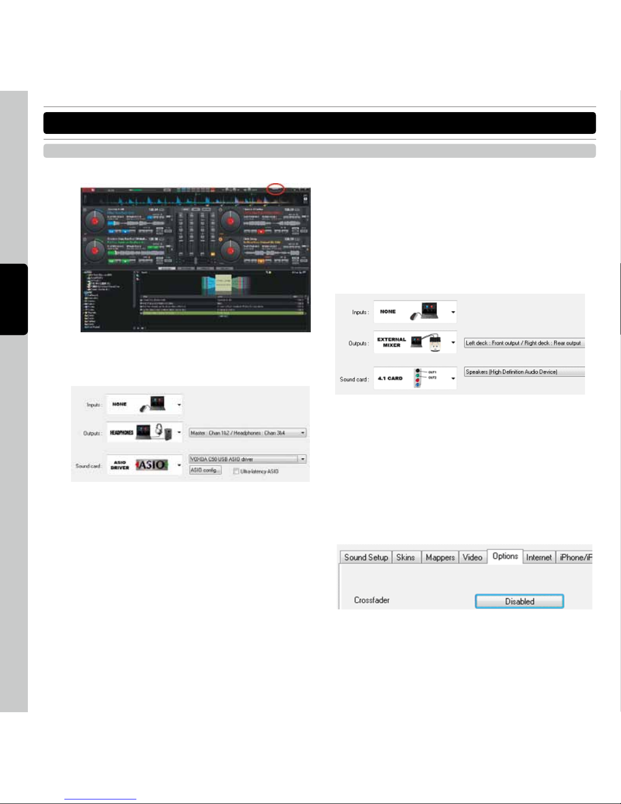
Click [CONFIG] located on the top right of VirtualDJ.
Step 2: Select [ASIO for C50 Driver] in the [Sound card]
tab,
INTERNAL MIXER MODE
Then select [Master: Chan 1&2/Headphones: Chan
3&4] in the [Outputs] tab.
EXTERNAL MIXER MODE
Left deck and right deck on separate outputs
With Inputs set to None, Outputs set to External Mixer,
and Sound card set to ASIO Driver; this is the most
common configuration that will be used. For the Outputs
the assignment is Left Deck: Chan 1&2 and Right Deck:
Chan 3&4. In this configuration, connections from the
1&2 and 3&4 outputs of the DeeJay Trim are connected
to the appropriate Line level input channels on the mixer.
In all these situations, it is important to understand that
when using an external mixer; VirtualDJ's internal mixer
is not necessary. Most importantly, you should disable
VirtualDJ's internal crossfader to ensure 100% output
is provided to each of the assigned deck outputs.
Disabling the internal crossfader is done by selecting the
Options tab from the configuration dialog, then clicking
on the Crossfader option button until the word “Disabled”
appears.
AUDIO INTERFACE SETUP FOR VIRTUALDJ
Page 14

41
E N G L I S H
AU DIO SE TUP
LINE INPUTS MODE
VirtualDJ can also be configured to pass the line inputs
of the sound card through so ftware interface. As
depicted in the below images, the sound configuration
being used is with the Inputs set to the LINE-INs option.
Then by assigning the VDJScript action “linein” to an
available deck, the audio sent in on the line input will
pass through VirtualDJ providing a rhythm wave display
and dynamic BPM display on the deck.
The appropriate VDJScript syntax is “deck # linein #” –
replacing the # symbols with the appropriate deck and
line numbers. The example below is using a 6 deck
skin and assigning decks 5 and 6 to line inputs 1 and 2
respectively.
DVS MODE (with Timecode Vinyl or CDs)
Timecode setup can be used with either the External
Mixer option. To setup VirtualDJ for use with Timecode
Vinyl or CDs, change the Inputs option to Timecode.
TIMECODE (Single Deck) CONFIGURATION
For use with a single timecode source, chose the Single
Timecode option from the Input drop-down.
TIMECODE (Dual Deck) CONFIGURATION
For use with 2 Timecode input sources, choose the
Timecodes option from the Input drop-down.
Just li ke in ch anging t h e outpu t s aro u n d if t h e
connection s to the i nput so urc es a re inc orrectl y
connected, you can choose to reverse the settings from
the input drop-down from Chan 1&2: Left Deck / Chan
3&4: Right Deck to Chan 1&2: Right Deck / Chan 3&4:
Left Deck.
Page 15

42
E N G L I S H
AU DIO SE TUP
AUDIO INTERFACE SETUP FOR TRAKTOR
1.Open the Preference menu (click the icon on the right
top of the screen that looks like a gear wheel).
2.Open “Audio Setup” located on the left top.
3.Click on the “Audio Device” box and choose “VOXOA
C50 USB ASIO driver”
4.Open Output Routing
INTERNAL MIXER MODE
Set “Mixing Mode” as “Internal”
Set “Output Monitor” (Output to headphone)
Windows MAC OS
RCA Left OUT 3 3: Back Left
RCA Right OUT 4 4: Back Right
Set “Output Master” (Output to speakers)
Windows MAC OS
RCA Left OUT 1 1: Front Left
RCA Right OUT 2 2: Front Right
EXTERNAL MIXER MODE
Set “Mixing Mode” as “External”
Set “Output Monitor” (Output to headphone)
Windows MAC OS
RCA Left OUT 1 1: Front Left
RCA Right OUT 2 2: Front Right
Set “Output Master” (Output to speakers)
Windows MAC OS
RCA Left OUT 3 3: Back Left
RCA Right OUT 4 4: Back Right
Page 16

43
E N G L I S H
CO NNE CTI ONS
RCA USB
Type B
6.3mm 3.5mm
Microphone
Computer
MP3 Player
CD/MP3 PlayerTurntable
Main balanced power amplifier
Main unbalanced power amplifier
Page 17

44
E N G L I S H
PA RT NAM ES AND FUNCTIO NS
MIXER SECTION
2
3
4
5
1
1. INPUT 1 Indicator
To indicate the INPUT 1 THRU is active.
When the INPUT 1 over 2V the PEAK indicator will light
2. MIC Indicator
To indicate the MIC is active.
3. INPUT 1 Source switch
Can switch between AUX or LINE/PHONO1.
4. INPUT 2 Source switch
Can switch between MIC or LINE/PHONO2.
5. Master Volume Control
This rotary knob is is used to control the master output level (volume). To avoid distorted output try to maintain
an verage output signal level.
To avoid speaker damage that may be caused by excessive volume, be sure this adjustment always set to
zero before turning the unit on.
Page 18

45
E N G L I S H
6. MIC jack
This jack is used to connect a microphone to the mixer. Connect your microphone via 1/4 inch jack. The volume
output level for microphone will be controlled by its own respective VOLUME KNOB.
7. MIC Level control
The rotary knobs control the output volume of MICROPHONE.
8. MIC On/Off switch
To set MIC on and off.
9. Touch Sensor Level control
Adjust level of touch sensitivity for the Jog Wheel.
10. X-Fader Curve switch
Allow Allows adjusting the slope of corssfader. Rotate clockwise to shorten fade time with sharper cut off at
either end Rotate anti-clockwise to lengthen fade to gradually mix across fader and 50/50 mix in center only.
11. Monitor Mixing Mode selector
This function allows you to monitor the Cue level as well as the Master (main output) level in your headphones.
Channels Cue Level may only be monitored if the channel CUE function is selected. To select a channel cue
function press the CUE BUTTON that is directly associated with the specific channel you wish to monitor. You
may use the mixing function to blend both the Cue level and the MASTER level together.
12. Cue Level control
This rotary knob is used to adjust the headphone volume output level. Turn the knob in a clockwise direction to
increase the headphone volume.
13. Phones jacks
These jacks are used to connect your headphones to the device allowing you to monitor the cue channel.
Always be sure the CUE LEVEL VOLUME is set to minimum before you put the headphones on.
PA RT NAM ES AND FUNCTIO NS
FRONT PANEL
6 7 8 9 9 10 11 12 13
Page 19

46
E N G L I S H
PA RT NAM ES AND FUNCTIO NS
REAR PANEL
14. Power cord fastener
To fasten the power cord to avoid unplugging the cord by accident.
15. Power Connector
Plug in power adapter here. Please use only a 6V 2.0A DC adaptor.
16. Power Switch
Turn this unit power ON/OFF.
17. USB MIDI port
Connect the USB port to a unengaged USB port of your computer via USB cable.
NOTE
: USB cable no more than 3m long.
18. Balanced XLR Master Output jack
Used to connect to the amplifier for professional use. Specially when cable lines are long and therefore can
caught unwanted noise.
19. RCA Master Output jack
The RCA jacks send a low current unbalanced output signal.
20. Phono/ Line Selector switch
These switches are used to change the voltage line levels of the respected PHONO/ LINE RCA inputs jacks.
When connecting turntables with magnetic cartridges to these jacks be sure the corresponding switch is in the
PHONO” position, and when using line level input devices be sure the switch is in the “LINE” position.
NOTE
: Always be sure main power is shut off before change the position of the Line Level Selector Switch.
21. GND (Ground Terminal)
For turntable connection. Always use this connection when using standard turntables with ground cable.
252423222120191817161514
Page 20

47
E N G L I S H
PA RT NAM ES AND FUNCTIO NS
22. Channel Phono/Line input connector
Turntables equipped with MM pickup cartridge (All DJ turntable use MM pickup cartridges) may be connected to
these jacks as long as the PHONO/ LINE selector switches is in the “PHONE” position. CD players, Tape Decks
and other line level instruments may only be connected to these jacks as long as the PHONO/ LINE selector
switches is in the “LINE” position. Input volume will be controlled by the Channel gain control knob.
23. PC/THRU switch
Send the AUX or LN/PH 1 signals directly to the master out and disconnects the computer output. Select the
AUX or LN/PH1 from the Input1 selection.
24. AUX In jack
CD players, MP3 Player, Tablet Pad and other line level instruments may only be connected to this jack. Input
volume will be controlled by the channel fader. The channel SOURCE SELECTOR SWITCH must be in the "Aux"
position, to monitor any source connected to this jack.
25. INPUT 1 gain
These knobs are used to adjust the audio source signal input gain for a channel. Never use the gain control to
adjust a channels output volume. Setting the gain level properly will ensure a clean output signal.
Page 21

48
E N G L I S H
SO FTW ARE CO NTR OL FOR V IRT UAL DJ
FUNCTIONS MAP
1
2
3
4
5
6 7 8
9 10 11 12
13 14 15 16
17
25
26
27
28 29 30 31
32
33
35
37
40
41
42
43
44
45
46 47 48 49 50 51 52 53
54
55
56
57 58
60 61
59
6264 65
63
34
36
39
38
66
67
6869 70
19 20
22
23
24
18
21
Page 22
49
E N G L I S H
SO FTW ARE CO NTR OL FOR V IRT UAL DJ
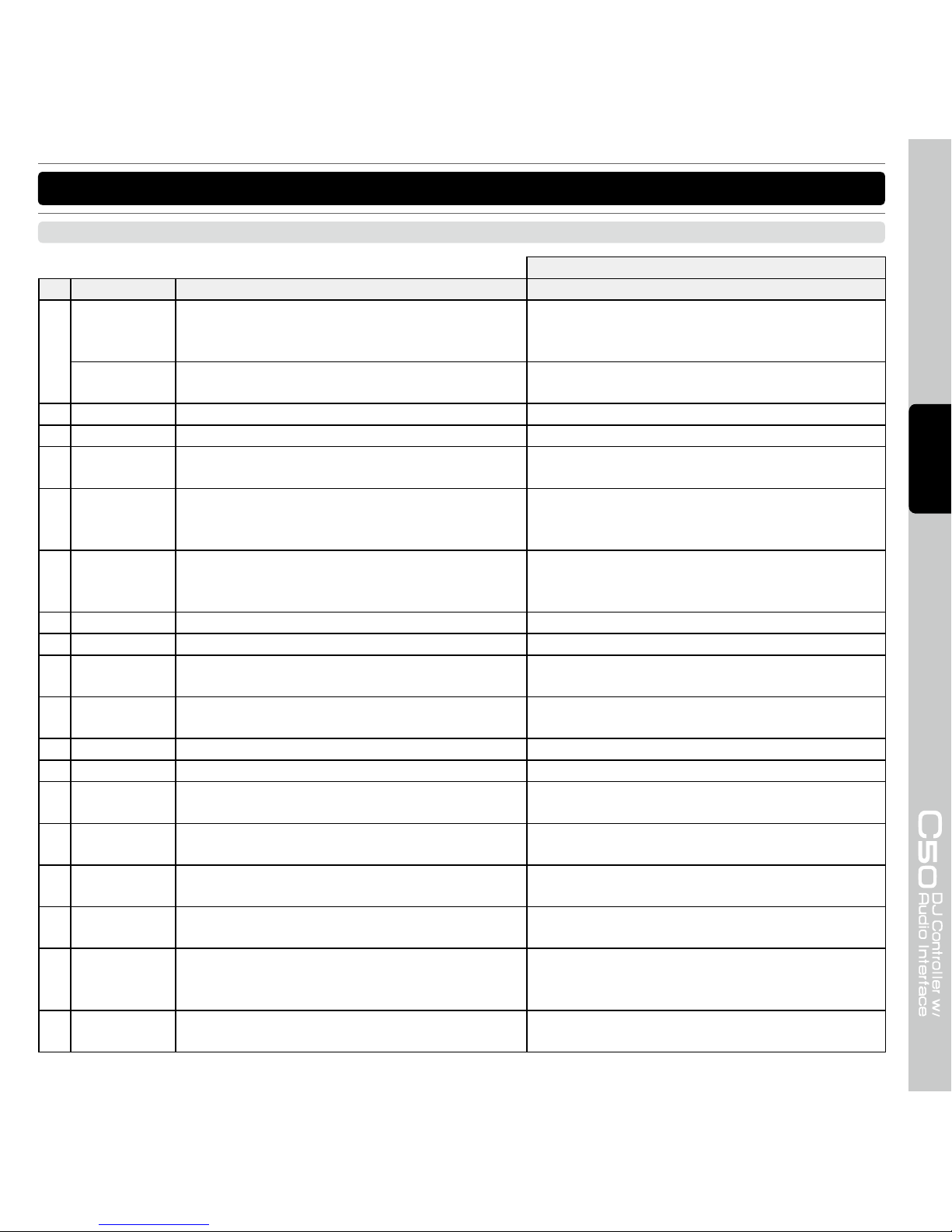
SHIFT+
No. Items Description Description
1 Auto Loop Active smart loop function when smart_play is
activated, songs are automagically synchronized
when played.
NONE
Auto Loop Set the loop size (or default loop size if no loop
is active)
Move the loop left/right by 4 beats
2 FX1 on Start or stop the ECHO effect Start or stop the FILTER effect
3 FX2 on Start or stop the FLANGER effect Start or stop the BACKSPIN effect
4 Pitch Fader Se t th e pitch of the dec k, t o be us ed b y
hardware controllers.
NONE
5 IN Set loop in point. if not in loop, set the begining
of a loop. if in loop, jump back to the begining
of the loop.
NONE
6 OUT Set loop out point. if not in loop, set the deck in
loop, starting from the last set loop_in point or
stutter point. if in loop, exit the loop.
NONE
7 Loop Active Reloop or loop active.Jump to the loop_in point. Remove the loop.
8 Delete Hold this button to delete hot cue NONE
9 Hot Cue 1 Sets Hot Cue 1 and Play.
Move backward the song while the button is
pressed
10 Hot Cue 2 Sets Hot Cue 2 and Play.
Move forward the song by 4 beat while the button
is pressed
11 Hot Cue 3 Sets Hot Cue 3 and Play. Jump to previous cue point
12 Hot Cue 4 Sets Hot Cue 4 and Play. Jump to next cue point
13 Sample 1 / 5
Left Deck play sample 1 Right Deck play sample 5
Left Deck play sample 1 Right Deck play sample
5. if already playing, restart from begining.
14 Sample 2 / 6
Left Deck play sample 2 Right Deck play sample 6
Left Deck play sample 2 Right Deck play sample
6. if already playing, restart from begining.
15 Sample 3 / 7
Left Deck play sample 3 Right Deck play sample 7
Left Deck play sample 3 Right Deck play sample
7. if already playing, restart from begining.
16 Sample 4 / 8
Left Deck play sample 4 Right Deck play sample 8
Left Deck play sample 4 Right Deck play sample
8. if already playing, restart from begining.
17 Key Lock
Activate/deactivate the key lock (to make the pitch
slider change the speed of the song, but keep the
key of the song like it is now).
NONE
18 Deck Switch Deck change between A/C B/D Select PLAYER/LOOPS/EFFECTS screen on the
deck
CONTROL & FUNCTIONS
Page 23
50
E N G L I S H
SO FTW ARE CO NTR OL FOR V IRT UAL DJ
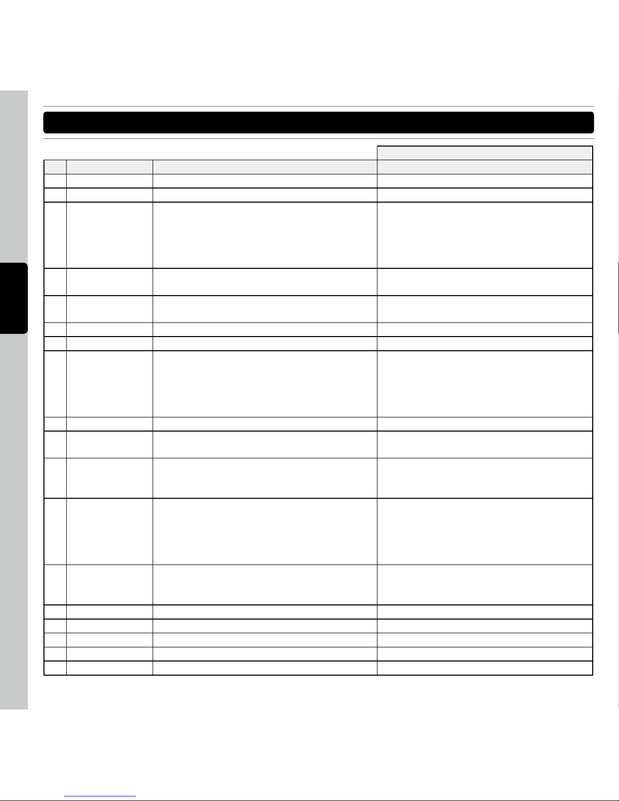
SHIFT+
No. Items Description Description
19 Deck A (B) Led Indicate current deck
20 Deck C (D) Led Indicate current deck
21 Sync/Master Synchronize the song with the other deck. S e l e c t /u ns el ec t this deck as 'm as te r
deck ' . When a maste r deck is set, all
synchronization operations will take the
master deck as reference. (for skins with
more than 2 decks)
22 Pitch Bend - Applies pitch bend -2% 500ms Set the range for the pitch slider. Pitch range
"6,10,16,100" -1
23 Pitch Bend + Applies pitch bend +2% 500ms Set the range for the pitch slider. Pitch range
"6,10,16,100" +1
24 Scratch Set the jogwheel in vinyl mode (with scratch) Hold to play the song backward
25 Jog Wheel touch Touch the surface of wheel to scratch
26 Jog Wheel Locate cue points, scratch the song playback
and tempo bend Outer rim : tempo bending. In
Loop : hold Loop IN/Loop Out and spin the jog
wheel to fine-tune the Loop in point/Loop out
point
Seek through track (fast forward / rewind)
27 Jog Wheel Rim Pitch Bend
28 SHIFT Press or ho l d to access th e se c ondary
functions of other control elements
29 Cue Play If playing, pause and go to the last cue point. if
paused, set the current position as cue point,
and preview the cue as long as pressed.
Tap on a few beats to set a new bpm for the
song if the application didn't got it right on
the first time.
30 Cue If playing, go to the last cue point and continue
playing. if paused, set the current position
as cue point, and preview the cue as long as
pressed. if in loop, change loop_in to the cue
point but keep the loop's length.
Automatically goes to the first beat in the
song
31 Play/Pause If paused, start the deck. if playing, pause the
deck. Button lights up when playing. Blinking
while cue
I
nstantly synchronize the song with the other
deck, using local beat information instead of
the gloabl beatgrid, but don't change the pitch.
32 Channel Gain Set the channel gain
33 Channel High Set the treble equalizer
34 Channel High Kill Mute the treble
35 Channel Mid Set the medium equalizer Change the key of the song
36 Channel Mid Kill Mute the medium Active/Deactive the Key function
Page 24
51
E N G L I S H
SO FTW ARE CO NTR OL FOR V IRT UAL DJ
SHIFT+
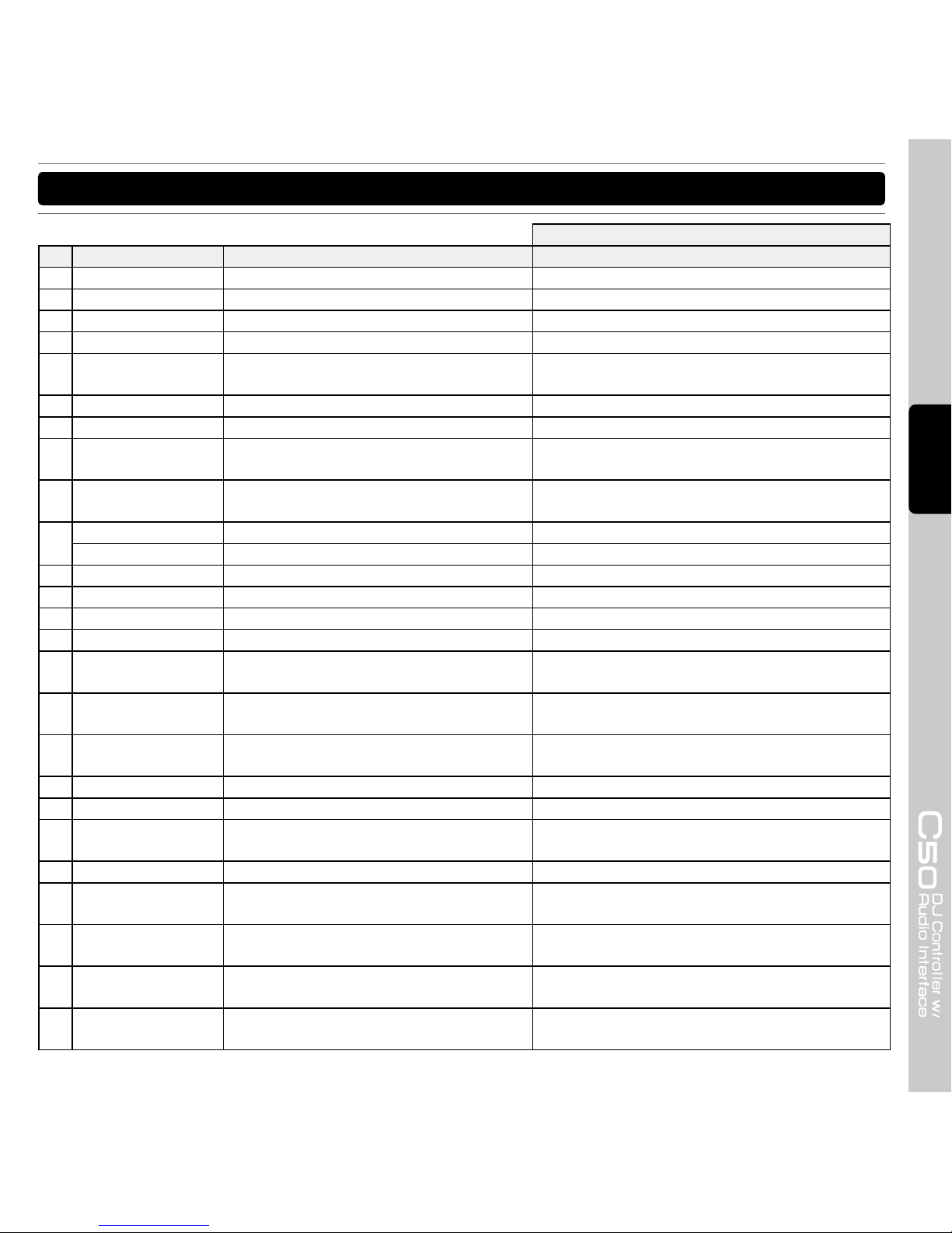
No. Items Description Description
37 Channel Key On Indicate the Key function is ON
38 Channel Low Set the bass equalizer Adjust the Filter
39 Channel Low Kill Mute the Bass Active/Deactive the Filter
40 Channel Filter On indicate the Filter is ON
41 Channel Cue Select the deck to the headphones Left De c k PFL: Op e n the Mix e r windo w
Right Deck PFL: Open the Video window
42 Channel Fader Adjust the level of the selected channel
43 Channel Meter Get the value of the incoming vu-meter
44 Master Meter Left Get the value of the outgoing vu-meter for
the left balance
45 Master Meter Right
Get the value of the outgoing vu-meter for
the Right balance
46 FX ENC Button
none
FX ENC Selects a effect from the list Select a sample
47 FX ON button Start or stop selected effect
48 FX Knob 1 Controls the effect parameter 1
49 FX button 1 Effect button 1
50 FX Knob 2 Controls the effect parameter 2
51 FX button 2 Ef f e c t button 2 (Only support e d in
selected effect plugings).
52 FX3 Knob 3 Chang e the vol u m e of th e select e d
sample
53 FX3 button 3 Play/Stop the selected sample Play the selected sample. if already playing,
restart from begining.
54 Master Change the volume of the Master output
55 Booth Change the volume of the booth output
56 Browser button Songs: Adds song to playlist Folders:
Enter folder
Zoom or unzoom the browser to be displayed on
the whole window
Browser ENC Scrolls file/folder list
57 Load A/C Loads the selected song on the deck A/C Ch ange the page displayed in the browser
window (folders, songs, playlist, sidelist)
58 Load B/D Loads the selected song on the deck B/D Change the page d isplayed in the brow ser
window (folders, songs, playlist, sidelist)
59 C e n t e r E n c o de r
Button
Launch a transition from one video deck
to the other.
Activate/deactivate the selected video effect
Center Encoder S e l e ct t h e pl u gi n us e d fo r v i de o
transitions.
Selects a video effect
Page 25
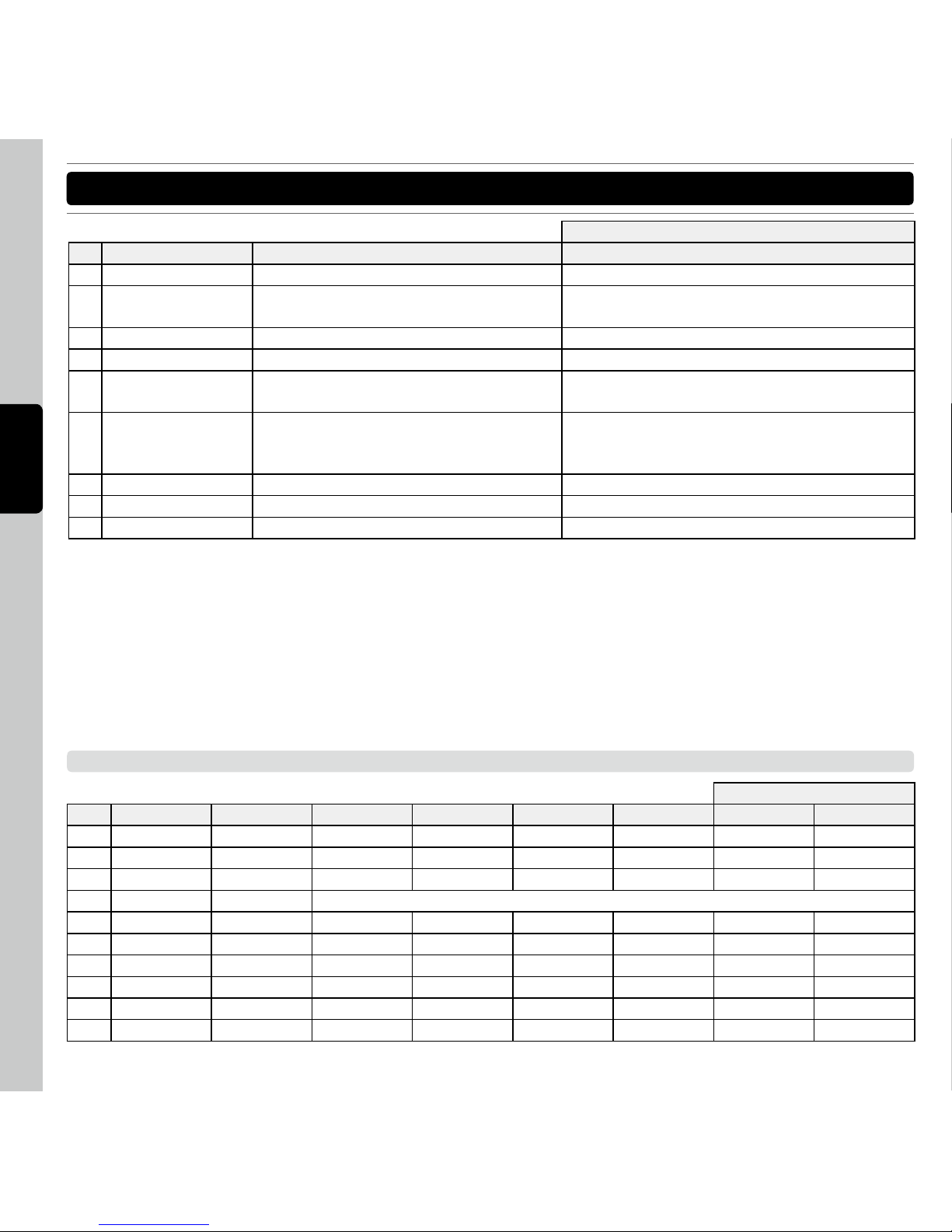
52
E N G L I S H
SO FTW ARE CO NTR OL FOR V IRT UAL DJ
SHIFT+
No. Items Description Description
60 TX (Transition) LED indicate the video transition is on
61 F X (V id e o Eff e c t )
LED
indicate the video effect is on
62 Audio Cross Fader Crossfader
63 Video Cross Fader Set the position of the video crossfader
64 Video X-fader Active Press to active the crossfader as Video
crossfader
65 Video X-fader link Link or unlink the video crossfader to the
audio crossfader
move the vi d eo crossfade r autom a tically
according to which side is playing, cueing,
scratching, etc…
66 Cross Fader Curve Select the curve of the crossfader
67 Cue Mixing Change the mix of the PFL
68 Cue Level Change the volume of the PFL output
MIDI MAP (HEX)
SHIFT +
No. Items Type SW Note VR CC LED Note LED CC SW Note VR CC
1 Auto Loop SW/ENC 1 1 -- -- 33 1F
2 FX1 on SW/LED 2 -- 2 -- 34 -3 FX2 on SW/LED 3 -- 3 -- 35 -4 Pitch Fader VR En,0xll(LSB),0xmm(MSB)
5 IN SW/LED 4 -- 4 -- 36 -6 OUT SW/LED 5 -- 5 -- 37 -7 Loop Active SW/LED 6 -- 6 -- 38 -8 Delete SW/LED 7 -- 7 -- 39 -9 Hot Cue 1 SW/LED 8 -- 8 -- 3A -10 Hot Cue 2 SW/LED 9 -- 9 -- 3B --
Page 26

53
E N G L I S H
SO FTW ARE CO NTR OL FOR V IRT UAL DJ
SHIFT +
No. Items Type SW Note VR CC LED Note LED CC SW Note VR CC
11 Hot Cue 3 SW/LED A -- A -- 3C -12 Hot Cue 4 SW/LED B -- B -- 3D -13 Sample Deck 1(2) Slot 1 SW/LED C -- C -- 3E -14 Sample Deck 1(2) Slot 2 SW/LED D -- D -- 3F -15 Sample Deck 1(2) Slot 3 SW/LED E -- E -- 40 -16 Sample Deck 1(2) Slot 4 SW/LED F -- F -- 41 -17 Key Lock SW/LED 10 -- 10 -- 42 -18 Deck Switch SW 11 -- -- -- 43 -19 Deck A (B) Led none -- -- -- -- -20 Deck C (D) Led none -- -- -- -- -21 Sync/Master SW/LED 12 -- 12 -- 44 -22 Pitch Bend - SW/LED 13 -- 13 -- 45 -23 Pitch Bend + SW/LED 14 -- 14 -- 46 -24 Scratch SW/LED 15 -- 15 -- 47 -25 Jog Wheel touch SW 26 -- -- -- 58 -26 Jog Wheel Enc -- 2 -- -- -- 20
27 Jog Wheel Rim none -- -- -- -- -- -28 SHIFT SW/LED 2D -- 2D -- -- -29 Cue Play SW/LED 16 -- 16 -- 48 -30 Cue SW/LED 17 -- 17 -- 49 -31 Play/Pause SW/LED 18 -- 18 -- 4A -32 Channel Gain VR -- 3 -- -- -- 21
33 Channel High VR -- 4 -- -- -- 22
34 Channel High Kill SW/LED 19 -- 19 -- 4B -35 Channel Mid VR -- 5 -- -- -- 23
36 Channel Mid Kill SW/LED 1A -- 1A -- 4C -37 Channel Key On LED -- -- 26 -- -- -38 Channel Low VR -- 6 -- -- -- 24
39 Channel Low Kill SW/LED 1B -- 1B -- 4D -40 Channel Filter On LED -- -- 27 -- -- -41 Channel Cue SW/LED 1C -- 1C -- 4E -42 Channel Fader VR -- 7 -- -- -- 25
43 Channel Meter VR LED -- -- -- 2 -- -44 Master Meter Left VR LED -- -- -- 3 -- -45 Master Meter Right VR LED -- -- -- 4 -- -46 FX1 (2) Enc SW/ENC 1D 8 -- -- 4F 26
Page 27
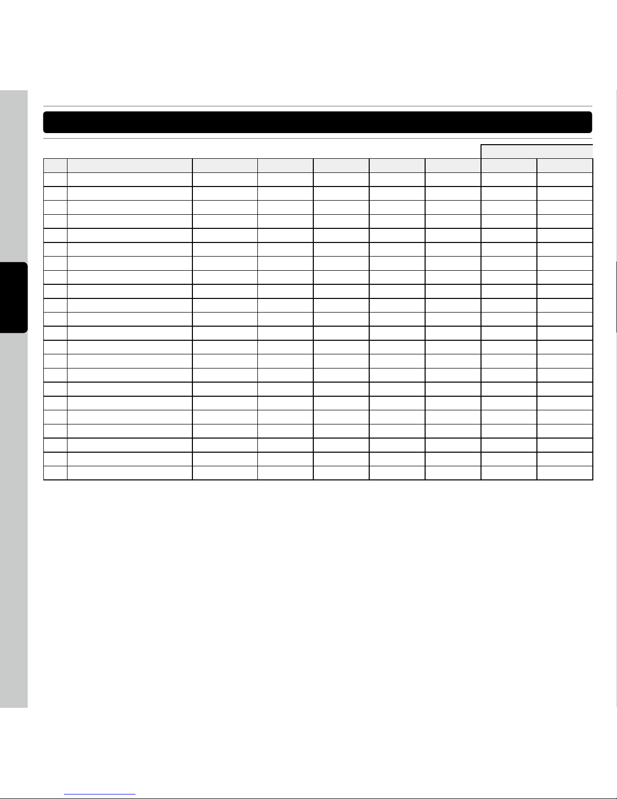
54
E N G L I S H
SO FTW ARE CO NTR OL FOR V IRT UAL DJ
SHIFT +
No. Items Type SW Note VR CC LED Note LED CC SW Note VR CC
47 FX1 (2) on button SW/LED 1E -- 1E -- 50 -48 FX1 (2) Knob 1 VR -- 9 -- -- -- 27
49 FX1 (2) button 1 SW/LED 1F -- 1F -- 51 -50 FX1 (2) Knob 2 VR -- A -- -- -- 28
51 FX1 (2) button 2 SW/LED 20 -- 20 -- 52 -52 FX1 (2) Knob 3 VR -- B -- -- -- 29
53 FX1 (2) button 3 SW/LED 21 -- 21 -- 53 -54 Master VR -- C -- -- -- 2A
55 Booth VR -- D -- -- -- 2B
56 Browser SW/ENC 27 E -- -- 59 2C
57 Load A/C SW/LED 22 -- 22 -- 54 -58 Load B/D SW/LED 23 -- 23 -- 55 -59 Video Enc SW/ENC 28 F -- -- 5A 2D
60 TX LED LED -- -- 2E -- -- -61 FX LED LED -- -- 2F -- -- -62 Audio Cross Fader VR -- 10 -- -- -- 2E
63 Video Cross Fader VR -- 11 -- -- -- 2F
64 Cross Fader Button1 SW/LED 24 -- 24 -- 56 --
65 Cross Fader Button2 SW/LED 25 -- 25 -- 57 -66 Cross Fader Curve VR -- 12 -- -- -- 30
67 Cue Mixing VR -- 13 -- -- -- 31
68 Cue Level VR -- 14 -- -- -- 32
Page 28

55
E N G L I S H
SP ECI FIC ATI ONS
1. GENERAL SECTION
POWER :
DC6V, 2.0A ; 12WATTS
DIMENSION :
410 (W) X 297 (D) X 65 (H) mm
WEIGHT :
3.2 kg
2. INPUT/OUTPUT IMPEDANCE & SENSITIVITY: (MAXIMUM GAIN, load=100K)
‧
INPUT IMPEDANCE AND REFERENCE INPUT LEVEL
LINE: 47K OHM /0dBV
PHONO: 47K OHM /-50dBV
MIC: 10K OHM /-54dBV
AUX: 47K OHM /0dBV
‧
OUTPUT IMPEDANCE
MASTER: 300 OHM
BALANCED: 600 OHM
PHONES (load=32 ohm): 10 OHM
3. FREQUENCY RESPONSE: (MASTER GAIN MAX., MASTER OUT 0dB)
LINE: 20-20KHz +/-3dB
AUX: 20-20KHz +/-3dB
PHONO: 20-20KHz +1/-3dB (RIAA) (MASTER OUT -14dB)
MIC: 20-20KHz +2/-3dB
4. THD+N: (MASTER GAIN MAX., MASTER OUT 0dB, w/ 20kHz LPF, A-WEIGHTED)
LINE: LESS THAN 0.05% @ 1KHz
AUX: LESS THAN 0.05% @ 1KHz
PHONO: LESS THAN 0.15% @ 1KHz
MIC: LESS THAN 0.15% @ 1KHz
5. MAXIMUM INPUT: (MASTER GAIN MAX., 1KHz, THD=1%, w/20kHz LPF, A-WEIGHTED)
LINE: MORE THAN +6dBV
AUX: MORE THAN +6dBV
PHONO: MORE THAN -30dBV
MIC: MORE THAN -35dBV
6. MAXIMUM OUTPUT: (MASTER GAIN MAX., 1KHz, THD=1%, w/20kHz LPF, A-WEIGHTED)
MASTER: MORE THAN +6dBV (2V)
275 mm
297 mm
410 mm
47 mm
65 mm
Page 29

56
E N G L I S H
SP ECI FIC ATI ONS
7. S/N RATIO: (MASTER GAIN MAX., MASTER OUT 0dB, w/20KHz LPF, A-WEIGHTED)
LINE: MORE THAN 80dB
AUX: MORE THAN 80dB
PHONO: MORE THAN 80dB
MIC: MORE THAN 75dB
8. LR SEPARATION: (MASTER GAIN MAX., MASTER OUT 0dB, w/ 20kHz LPF, A-WEIGHTED)
LINE:
MORE THAN 70dB
AUX:
MORE THAN 70dB
PHONO:
MORE THAN 70dB
9. CHANNEL BALANCE:
Within 2dB
10. USB SECTION: (SIGNAL FORMAT: MP3, 128KBPS, SONY SOUND FORGE8.0)
*1 (ASIO4ALL DEFAULT PLAYBACK DEVICE: C50 1/2 Windows Level At MAX. Out)
*2 (ASIO4ALL DEFAULT PLAYBACK DEVICE: C50 3/4 Windows Level At MAX. Out)
*3 (w/20KHz LPF A-WEIGHTED)
‧
OUTPUT LEVEL
MASTER OUT: 0dBV+/-1dB
BALANCE OUT: 2.22dBm +/-1dB
PHONES OUT: 0dBV+/-1dB*2
‧
CHANNEL BALANCE
Within 2dB
‧
FREQUENCY RESPONSE
MASTER OUT: 17-16KHz +1/-3dB
BALANCE OUT: 17-16KHz +1/-3dB
PHONES OUT: 17-16KHz +1/-3dB*2
‧
THD+N
MASTER OUT: LESS THAN 0.05%
BALANCE OUT: LESS THAN 0.05%
PHONES OUT: LESS THAN 0.15%*2,*3
‧
S/N RATIO
MASTER OUT: MORE THAN 80dB
BALANCE OUT: MORE THAN 80dB
PHONES OUT: MORE THAN 80dB*2,*3
‧LR
SEPARATION
MASTER OUT: MORE THAN 75dB at 1KHz
BALANCE OUT: MORE THAN 75dB at 1KHz
PHONES OUT: MORE THAN 60dB at 1KHz*2,*3
‧
RECORDING AND PLAYBACK
: (LINE INPUT 1KHz -8dBV, AUX INPUT 1KHz -8dBV, PHONO INPUT 1KHz
-44dBV, MIC INPUT 1KHz -48dBV PLAYBACK: MIC OFF *1,*3)
OUTPUT:
LESS THAN
-14dBV ± 2dB
THD+N:
LINE/AUX:
LESS THAN
0.05%
PHONO:
LESS THAN
0.15%
MIC:
LESS THAN
0.15%
Page 30

57
E N G L I S H
NO TE
Specifications and improvements in the design of this unit and this manual are subject to change
without any prior written notice.
www.voxoa-pro.com
Page 31

Printed in ChinaVERSION 1.0
 Loading...