

Page 1

Voxengo Primary User Guide
(for VST, VST3, AudioUnit, AAX audio software made by Voxengo)
https://www.voxengo.com/
Document revision date: 28-Feb-2019
Page 2

Voxengo Primary User Guide
2
Contents
Introduction 5
Common Features of Voxengo Audio Plug-Ins 5
User Interface Layout 6
Title Bar 6
Control Buttons 6
Plug-In Control Interface 6
Hint Line 6
Main Control Buttons 7
Plug-In Instance Name Edit Box 7
Oversampling Selector 7
Bypass Switch 8
A/B Switch Button 8
“A > B” (“B > A”) Button 8
Sat Switch 8
Standard Controls 9
Knob 9
Keyboard Value Entry 10
Value List Selector 10
Slider 10
Level Meter 10
Equalizer 11
Equalizer – Group Editing 12
Equalizer – Spectrum 13
Equalizer – Narrow-Band Sweeping 13
Envelope Editor 14
Quick Zoom-In 14
Scroller 14
Window Resizer 15
Spectrum Mode Editor 15
DC Filter Mode Editor 17
Copyright © 2007-2018 Aleksey Vaneev
Page 3

Voxengo Primary User Guide
3
Static Spectrums Editor 17
Undo/Redo 19
Preset Manager 20
Main Preset Manager 20
Local Preset Managers 21
Channel Routing Window 22
Layout 22
Input and Output Routing Selection 22
Show All Channel Meters 22
Mid-Side Pairs Selection 22
Channel Group Assignments 23
Key Signal Sources 23
In Channel Labels 24
Group Names 24
Routing Presets 24
Channel Group Selector 25
Channel Group List 25
Plug-In Settings for a Specific Plug-In 26
Color Scheme 26
User Interface Scale 26
Min Infrastructure 26
Show Groups Bar 26
Oversampling 26
Meter “Density Mode” 27
Meter Integration Time 27
Meter Release Time 27
Meter Peak Level Hold Time 28
Global Voxengo Software Settings 29
Auto Oversampling Level 29
Mouse Wheel Precision 29
Shift Key Precision 29
Drag Precision 29
Copyright © 2007-2018 Aleksey Vaneev
Page 4

Voxengo Primary User Guide
4
Show Preset Selector 29
Show Knob Labels 29
Tablet Mode 29
Show Virtual Keyboard 30
Remember Window Positions 30
Enable Mouse Wheel On Lists 30
Curve Drag Adds Points 30
Radial Knob Mode 30
Control Surface Crosshair 30
Show All Filter Shapes 30
Show Colorized Filter Shapes 30
Do Not Show Latency Changes 30
Anti-Denormal Noise 31
VST 2 Function Sync 31
No Multi-Channel Operation 31
Visual Settings 31
Plug-In Files’ Locations 32
Additional Information 33
Selecting Best Audio Block Size 33
64-Bit Audio Processing 33
Plug-In Registration/Authorization 33
CPU Load Measurement Notice 33
Knowledge Bit – Correlation 34
Stereo Correlation 34
Knowledge Bit – Aligning Microphones 35
Alignment Steps 35
Microphone Delay Alignment 35
Microphone Phase Alignment 36
Microphone Gain Alignment 36
High-Frequency Drop Issue 37
Why Go Multi-Microphone? 37
Questions and Answers 38
Copyright © 2007-2018 Aleksey Vaneev
Page 5

Voxengo Primary User Guide
5
Introduction
Voxengo audio plug-ins feature a set of standard interface elements that are shared
among all Voxengo plug-ins.
This guide describes functionality of these elements, focusing on the interaction
between the user and the plug-in. This means that this guide does not describe an
actual application of user interface elements (some may control Gain, some may
control Frequency, etc.), but shows the ways of using these elements efficiently from
the user perspective. After reading this guide you will be able to use common
features of all Voxengo audio plug-ins. Any non-standard or special features are
described in the guides for the plug-ins that contain these non-standard or special
features, and are not covered by this guide.
Beside user interface description this guide contains important technical information
about Voxengo plug-ins.
Common Features of Voxengo Audio Plug-Ins
Preset manager
A/B comparison switch
Internal channel routing
Mid/side processing
Undo/redo history
Input channel naming
Channel grouping
Channel group naming
Settings (coloration, scale, hints)
Global settings (control precision, etc.)
Plug-in instance naming
Oversampling
Bypass switch
External side-chain (where applicable)
Contextual hint messages
Copyright © 2007-2018 Aleksey Vaneev
Page 6
Voxengo Primary User Guide
6
User Interface Layout
The graphical interface of every Voxengo plug-in consists of four distinctive parts: the
title bar, the control buttons array, the plug-in control interface and the hint line.
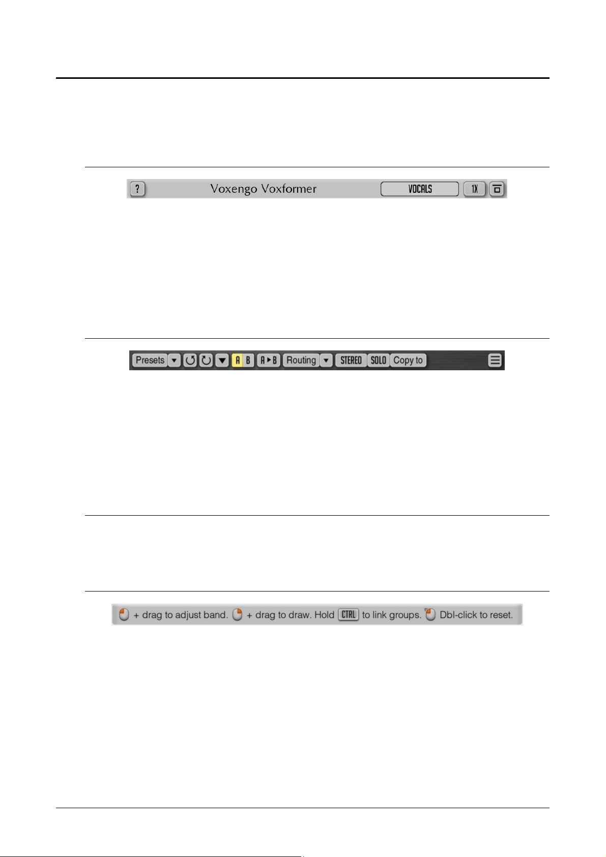
Title Bar
The title bar shows hint enable switch, plug-in’s title, and also contains the Plug-In
Instance Name text box, the Oversampling selector and the “Bypass” switch. Note
that this title bar will not be visible if the “Min Infrastructure” option in the “Settings”
window was enabled.
Some plug-ins have differently-looking title bar that only displays plug-in’s title with
one or several control buttons.
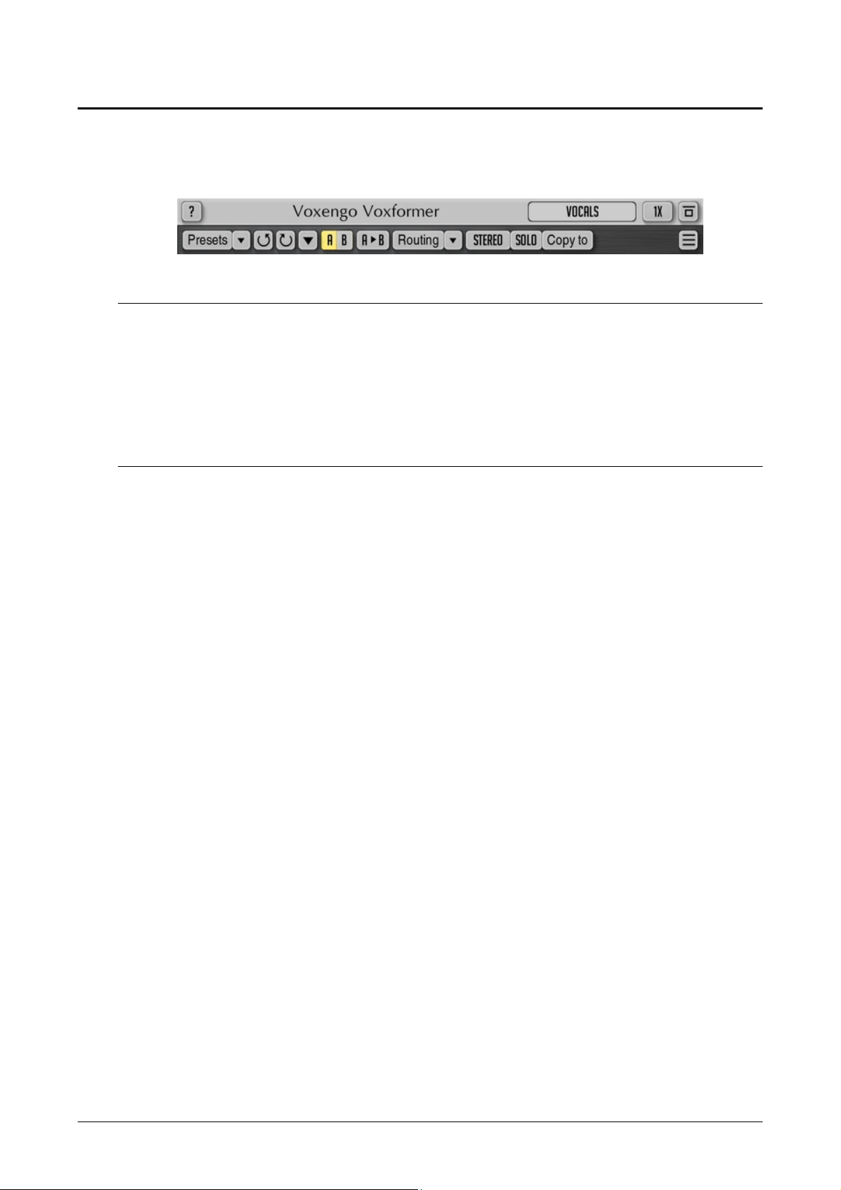
Control Buttons
This part of the user interface contains several control buttons: the “Presets” button
which opens the preset manager popup window; the quick preset selector “down”
button; three change history-related buttons; the A/B comparison button; the “A > B”
(“B > A”) button; the “Routing” button which opens the channel routing popup
window; the quick routing preset selector “down” button; the channel group selector;
and (at the far right) the “Settings” button which opens a popup window with the
plug-in’s copyright information and additional settings.
Plug-In Control Interface
This part of the plug-in varies greatly from plug-in to plug-in, and an in-depth
description is available on a per plug-in basis, in a separate user guide.
Hint Line
This interface element displays hint messages and may also display other
informational messages. The hint line can be enabled with the “?” button.
Copyright © 2007-2018 Aleksey Vaneev
Page 7
Voxengo Primary User Guide
7
Main Control Buttons
Every Voxengo plug-in features a set of standard control buttons. They are shown
and described below.
Plug-In Instance Name Edit Box
This control element allows you to give a name to the current plug-in instance. This
name is used for informative purposes only: it helps you to remember the purpose of
the plug-in, or gives you a note of a name of the host audio channel the plug-in is
inserted to. For example, the instance name can be set to “Vocals”, “Drum Bus”,
“Polysynth”, “Bass”, “Lead Guitar”, etc.
Oversampling Selector
This selector allows you to select a “quality factor” for the plug-in. An oversampling
allows a plug-in to run on a higher internal sample rate thus offering a better overall
sound quality. Almost all types of audio processes benefit from an oversampling:
probably, only gain adjustment, panning and convolution plug-ins have no real use
for it. An oversampling helps plug-ins to create more precise filters with minimized
warping at highest frequencies, to reduce spectral aliasing artifacts in compressors
and saturators, to improve a level detection precision in peak compressors. The
higher the oversampling setting is, the more CPU resources plug-in will require since
a CPU load is increased proportionally to the specified oversampling setting: at the
“8x” oversampling setting plug-in uses exactly 8 times more CPU time (and that is
excluding the time necessary to perform the oversampling itself).
The “Auto” oversampling option is the special option that enables the oversampling
when a project is being bounced (exported) to a wave file; in this mode, when the
plug-in works in the real-time mode the oversampling is set to the “1x” option (some
plug-ins may use “2x”). If the “Auto” option was not used then the selected option
will be used during bouncing. It should be noted that not all audio host applications
provide the plug-in with the required plug-in state information: in those cases the
“Auto” option works as the “1x” (or “2x”) option all the time (this is the case for some
older Mac OS X audio host applications that do not report the off-line bouncing state
to the plug-in). The “Auto” oversampling mode engages the “4x” oversampling mode
if the working sample rate is below 72 kHz; the “2x” mode is engaged if the sample
rate is below 144 kHz; otherwise the oversampling is not engaged at all (for example,
if the working sample rate is equal to 176.4 kHz or 192 kHz the oversampling is not
engaged). The maximum oversampling level used when the “Auto” mode is engaged
can be adjusted in the global settings window. Note that when the plug-in enters the
bouncing state, the “Off-Line Render” notification will be displayed on its interface.
When this notification is displayed, the “Auto” oversampling option will be working
correctly.
In the “Settings” window of most Voxengo plug-ins you can choose the oversampling
filter type to use. When the “Min-Phase” type is selected Voxengo plug-ins are using
poly-phase IIR low-pass filters with at least 106 dB stop-band attenuation and 6%
Copyright © 2007-2018 Aleksey Vaneev
Page 8

Voxengo Primary User Guide
8
transition band’s width (which starts at Fs/2) for the oversampling. Please note that
these poly-phase filters impose a phase coloration which sounds slightly different at
various working sample rates.
Voxengo plug-ins using the “Lin-Phase” filter type use linear-phase filters with 150
dB stop-band attenuation and 4% transition band’s width (centered at Fs/2). Note
that while working at 44.1 kHz sample rate, linear-phase oversampling filters will cut
frequencies above 20 kHz. This is a standard side-effect of oversampling and should
be considered normal.
Please also read the part titled “Oversampling” under the “Plug-In Settings for a
Specific Plug-In” topic.
Bypass Switch
The Bypass switch was mainly designed for evaluation of changes the plug-in made.
The Bypass switch will not reduce the plug-in's CPU load when switched on.
A/B Switch Button
By pressing the “A/B” switch button, you can switch between the current and an
opposite (“A” or “B”) plug-in states.
You can use the “A/B” switch button to copy programs between Session Bank’s slots.
To do so, in the Session Bank you first need to switch to a program you want to copy
and then press the “A > B” (or “B > A”) button. Next, switch to a program where you
want to put the first program and then finally press the “A/B” switch button again.
(The preset manager and its preset banks are discussed later in this guide.)
“A > B” (“B > A”) Button
The “A > B” (“B > A”) button copies the current plug-in state to an opposite state.
You may then switch to this opposite state by pressing the “A/B” button.
Sat Switch
Some plug-ins feature a built-in soft-knee output limiter. This switch enables this
limiter. This limiter controls output signal level and produces “console saturation”
effects. Note that neither limiter mode nor soft-clipping threshold is adjustable.
Copyright © 2007-2018 Aleksey Vaneev
Page 9
Voxengo Primary User Guide
9
Standard Controls
Knob
The knob control consists of four parts: the name of parameter it controls, the knob
position marker, the center of the knob, and the parameter value readout.
The knob position marker is represented by a rounded light indicator. You may drag
this marker to adjust the value of the parameter using the circular knob adjustment
approach: during dragging, you may move the mouse cursor farther away from the
knob to increase parameter value adjustment precision. You may click on the marker
to set the desired parameter value immediately. This way of adjusting the knob is
available only if the “Radial Knob Mode” global setting was enabled.
The center of the knob has a defined color that corresponds to the parameter or
parameter group the knob controls. You may drag the center of the knob to adjust
the value of the parameter with up and down mouse movements, linearly. While
dragging the center of the knob with the left mouse button, by additionally pressing
the right mouse button you can enable a high precision adjustment mode (which can
otherwise be enabled by holding down the “Shift” key). Dragging precision can be
adjusted in the global settings window.
The parameter value readout displays the current value of the parameter.
When knob is hovered with the mouse cursor, a scale ring is displayed that shows
approximate parameter values at different knob positions (“knob labels”). Thousand
values are suffixed with an asterisk (e.g. “2*”). This ring can be disabled in the global
settings window.
In some plug-ins you may use the right mouse button to enable knob linking. The
linking between knobs is available when two given knobs are logically linked (for
example, input and output gain knobs, low and high frequency knobs, etc.). You may
hold the “Ctrl” (“Command” on Mac OS X) key before dragging a knob with the right
mouse button to enable inverse knob linking: in this mode every positive increment
of the knob you drag results in a negative increment in the linked knob.
Knob can be also controlled with the mouse wheel. Double-clicking on the knob
resets it to the default state.
When working in surround, dual-mono or any other multi-group processing mode,
you may hold the “Alt” key to enable linked change of the knob in all channel groups
with active channels in them. This may not work for all knobs knob since such
feature may not be applicable to a parameter a particular knob controls.
Copyright © 2007-2018 Aleksey Vaneev
Page 10
Voxengo Primary User Guide
10
Keyboard Value Entry
Most readout values displayed on the user interface (gain, frequency, parameter value
readouts) can be clicked for keyboard value entry (some plug-ins whose parameter
value readouts can be dragged require double-click for keyboard entry).
Value List Selector
This type of control allows you to choose a value or an option from the list. You may
press the selector button with the left mouse button to display the value list. If you
later depress the mouse button on the desired value instead of the selector itself, the
list will be closed and the value on which you have depressed the mouse button will
be selected.
Note that mode preset lists are different to value lists in that mode preset lists do not
highlight a currently selected mode when you open the list.
Value and mode preset lists offer you additional ways of item selection without
opening the list: you may use mouse’s “forward” and “backward” buttons and mouse
wheel to scroll through the values. You may press the right mouse button on a value
selector (but not on a mode preset selector) to switch between the current and default
values.
Slider
Voxengo plug-ins feature horizontal and vertical sliders. A slider can be dragged with
the left mouse button to perform adjustments. While dragging the slider with the left
mouse button, by additionally pressing the right mouse button you can enable a high
precision adjustment mode (which can otherwise be enabled by holding down the
“Shift” key).
If plug-in presents you an array of sliders (like the “Overtone GEQ” plug-in does) by
holding down the right mouse button on the slider array you will engage the
“drawing” mode that allows you to position sliders in the “free-hand” mode.
Level Meter
Many Voxengo plug-ins feature standard level meters. Each level meter contains
level scale ruler (in decibel) and several level bars that correspond to channels (“A”,
Copyright © 2007-2018 Aleksey Vaneev
Page 11
Voxengo Primary User Guide
11
“B”, etc.) of the currently selected channel group (level meter displays all available
channels if the “Show All Channel Meters” switch was enabled in the “Channel
Routing” window). In some cases level meters are shown in the “minimal” variant
with only a single level bar present that averages level from all channels that belong
to the currently selected group. Gain reduction meters are displayed inversely (from
top to bottom), and may show positive gain reduction values since they are showing
gain reduction changes relative to the average gain reduction over 2-second time
frame.
Level meters may show a small horizontal white bar which represents peak level. In
output level meters such peak level may turn red which means that the output level
has entered the area above the 0 dBFS signal level and clipping may occur if the plugin stays last in the audio host application’s signal chain (if the plug-in is staying in the
intermediate position before other plug-ins clipping may not necessarily occur). In
non-output level meters used in the plug-in a red peak level may be only an
informative indication that some predefined threshold level was reached.
Level meter ballistics and peak level hold time can be defined for all instances of the
plug-in in the “Settings” window.
Output level meters usually feature the “Out/In” readout that displays the RMS level
difference between the input and output signals of the plug-in (this level difference
estimation is based on 3-second integration time).
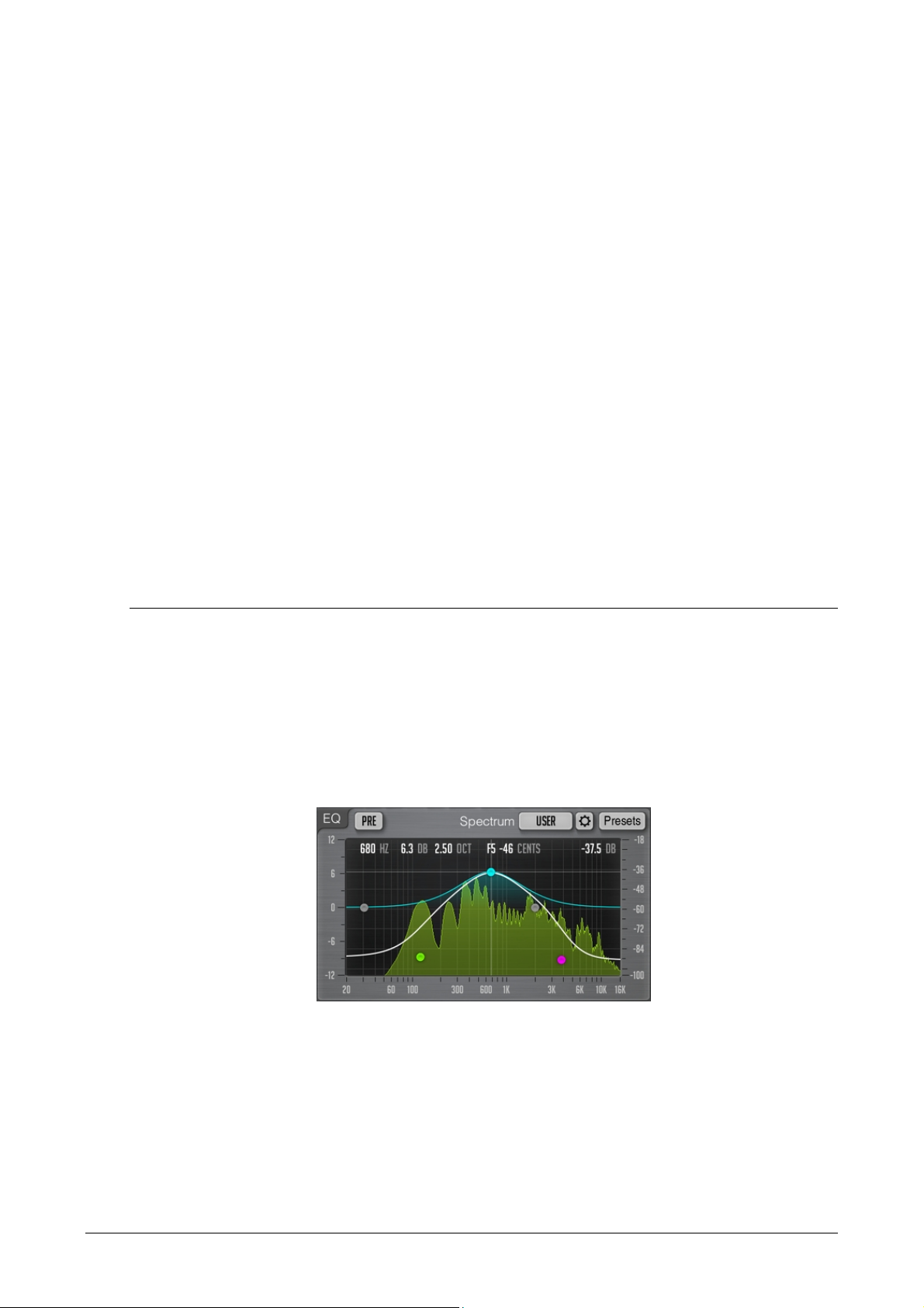
Equalizer
Several Voxengo plug-ins feature an equalizer with the built-in real-time spectrum
analyzer. While the visual appearance of the equalizer is similar among Voxengo
plug-ins, the equalizing algorithm used by any given plug-in may be different from
other plug-ins.
Note that information contained in this chapter applies to parametric equalizers only,
this part does not apply to envelope-driven equalizers like CurveEQ – please refer to
the Envelope Editor chapter for information on envelope editing.
This picture shows the “control surface” with control points which can be dragged
with the left mouse button to adjust the filter's gain and frequency that corresponds
to this control point (you may additionally hold the “Shift” key to enable precise
adjustments).
You may select the filter type of the control point by pressing the right mouse button
on that control point. By default, the filter type is set to “Off” making the control
point appear grey. Alternatively, you may use the mouse’s “forward” and “backward”
buttons to scroll through the filter types.
Copyright © 2007-2018 Aleksey Vaneev
Page 12
Voxengo Primary User Guide
12
The readouts you see show mouse cursor position within the control surface. The
readout also displays the musical note (and detune in cents) that corresponds to the
frequency position. The rightmost readout shows mouse cursor’s position within the
spectrum power range.
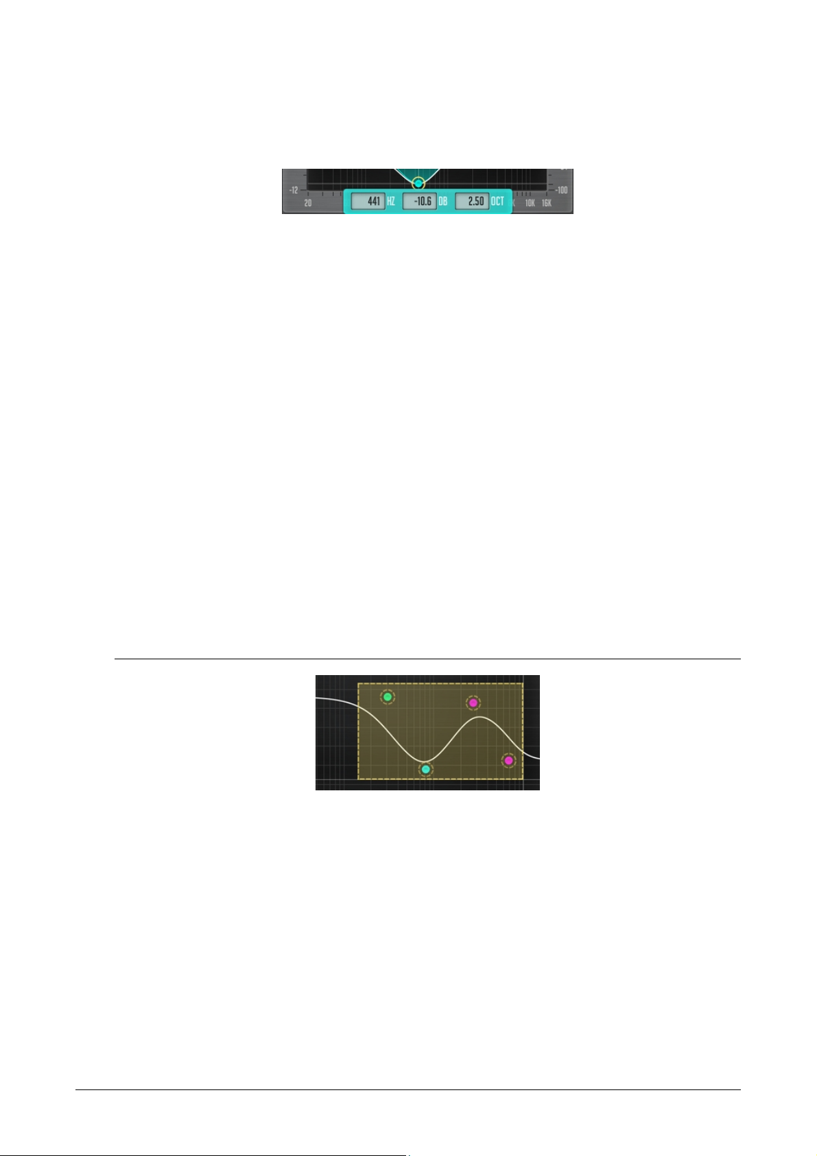
Clicking on a control point with the mouse button will cause the point to be encircled,
and the corresponding filter's frequency response curve will be shown in orange. The
white curve shown in the equalizer window shows the summary frequency response
of all currently enabled filters. When the control point is encircled, three entry fields
will be also displayed which you can use to specify filter’s parameters via keyboard
precisely (these entry fields may not be available in a particular plug-in).
While dragging a control point with the left mouse button, you can adjust the filter's
bandwidth by additionally holding the right mouse button (or holding down the “Alt”
key). Alternatively, you can use the mouse wheel to adjust the filter’s bandwidth.
You can hold the “Ctrl” (“Command” on Mac OS X) key while dragging a point to
enable its gain adjustment only; holding the “Ctrl” (“Command” on Mac OS X) and
“Alt” key simultaneously enables control point’s frequency adjustment only. Doubleclicking on a control point with the “Ctrl” (“Command” on Mac OS X) key held
returns this point to the 0 dB gain position.
Double-clicking on a control point without any key being held temporarily disables it.
Second double-click will re-enable the control point. A disabled control point will be
re-enabled whenever you move it. Some plug-ins may allow you to double-click or
Shift+Click the control surface anywhere to add a new filter (the filter type will be
auto-selected depending on the frequency where the filter was added at).
Equalizer – Group Editing
You can also perform editing operations on a group of control points. To select
several control points, drag inside the control surface itself. A box will appear, and all
control points inside this area will become selected. Later you can move a group of
selected points like you are working with a single point. To add control points to the
current selection, you have to hold the “Shift” key before starting to drag inside the
control surface. While holding the “Shift” key, instead of dragging you may also click
on the control point you want to add or remove to/from selection. If several points
were selected the double click on any of the selected points with the “Ctrl”
(“Command” on Mac OS X) key held will reset all selected points to 0 dB.
To deselect any currently selected points, simply click the control surface anywhere.
You may right-click the control surface to select all control points at once.
Copyright © 2007-2018 Aleksey Vaneev
Page 13

Voxengo Primary User Guide
13
If several control points are selected, dragging them up and down scales the gains of
these filters up and down, up to the point of gain inversion.
The “Presets” button opens preset manager for the equalizer.
Equalizer – Spectrum
Beside control points and frequency response plot the equalizer window also displays
the Fourier spectrum analysis plot. The spectrum analysis and displaying parameters
can be selected via the “Spec” mode selector. The “Spectrum Mode Editor” can be
used to customize these parameters further. You may also click the control surface
with the left mouse button anywhere to reset spectrum analysis display. Note that
Voxengo plug-ins use Hann windowing function to perform FFT analysis.
A red vertical line that can be displayed if the visible frequency range is wide: this line
shows maximal frequency of the input signal and depends on the input sample rate.
A second red vertical line may be displayed if oversampling is in use – this second
line informs you about the internal frequency range used by the plug-in at this
moment. Note that until you start the audio playback the red line may not be placed
correctly, because the plug-in may not know the correct input sample rate before the
audio processing was started.
Note that by default Voxengo plug-ins use 4.5 dB per octave slope for the spectrum
display which makes it look considerably “elevated” towards the higher frequencies in
comparison to most other spectrum analyzers available on the market. This setting
can be changed in the “Spectrum Mode Editor” window.
If the spectrum does not fit the display, you may adjust the visible spectrum range in
the “Spectrum Mode Editor” window.
Equalizer – Narrow-Band Sweeping
You may enable the “narrow-band sweeping” function by first holding the “Ctrl”
(“Command” on Mac OS X) key and then dragging the control surface with the left
mouse button. As a result of this action you will see the curve of the band-pass filter
that only passes the selected frequency range. You may adjust the bandwidth of the
filter with the mouse wheel. Such mode is useful at highlighting the resonances in the
sound.
Note that the band-pass filter’s curve is applied on top of the existing equalizer curve,
and so the curve you see when engaging the narrow-band sweeping is composed of
the existing equalizer curve and band-pass filter’s own equalizer curve.
Copyright © 2007-2018 Aleksey Vaneev
Page 14

Voxengo Primary User Guide
14
Envelope Editor
Some Voxengo plug-ins feature an envelope editor. The function set of this editor is
basically the same as that of the equalizer. The main difference lies in the manner the
curve is being drawn. Control points in the envelope editor are always connected by a
line or a smooth curve, without intersections, and there are no “filters” with their
corresponding “filter shapes” attached to each control point. In the envelope editor
you may add and remove control points freely by double-clicking or Shift+click in the
desired position within the envelope editor’s area.
To delete a control point you should double-click it. The leftmost and rightmost
control points cannot be deleted – they will be moved to envelope’s default position
when double-clicked. If you are double-clicking a control point with the “Ctrl”
(“Command” on Mac OS X) key held, the control point will be set to envelope’s
default position.
While any single control point can be moved freely around the control surface,
movements of grouped control points are constrained. There are two types of group
movements possible: when you drag a control point (when more than a single control
point is selected) the vertical movement is constrained and you can move points
horizontally; when you drag a line segment the horizontal movement is constrained
and you can move points vertically. If you hold the “Ctrl” (“Command” on Mac OS X)
while dragging the constraints are removed. The mouse wheel can be used to move
the control point closest to mouse cursor’s position vertically.
Quick Zoom-In
You may hold the Alt key while dragging the control surface to zoom-in the selected
spectrum area. Double-clicking the control surface with the left mouse button while
the Alt key is held acts as zoom-out function.
Scroller
Some Voxengo plug-ins feature horizontal and vertical scrolling controls with
zooming functionality. Such scrollers are usually attached to the sides of an equalizer
“control surface” discussed above. You may move a scroller only after using its
zooming function.
A pair of horizontal and vertical scrollers is accompanied by a rhomb which can be
used to control position of both scrollers at once in a single X-Y coordinate space.
Copyright © 2007-2018 Aleksey Vaneev
Page 15
Voxengo Primary User Guide
15
Scrollers and rhombs can be double-clicked to switch the visual state of the view they
are attached to. You may use this functionality to quickly switch between zoomed
and non-zoomed visual states of a view.
Window Resizer
This control that is present in some Voxengo plug-ins and is located in the bottom
right corner of the user interface window can be dragged to adjust the size of the
window. Note that some audio host applications may not allow you to adjust plugin’s window freely – in that the window will appear cropped after resize.
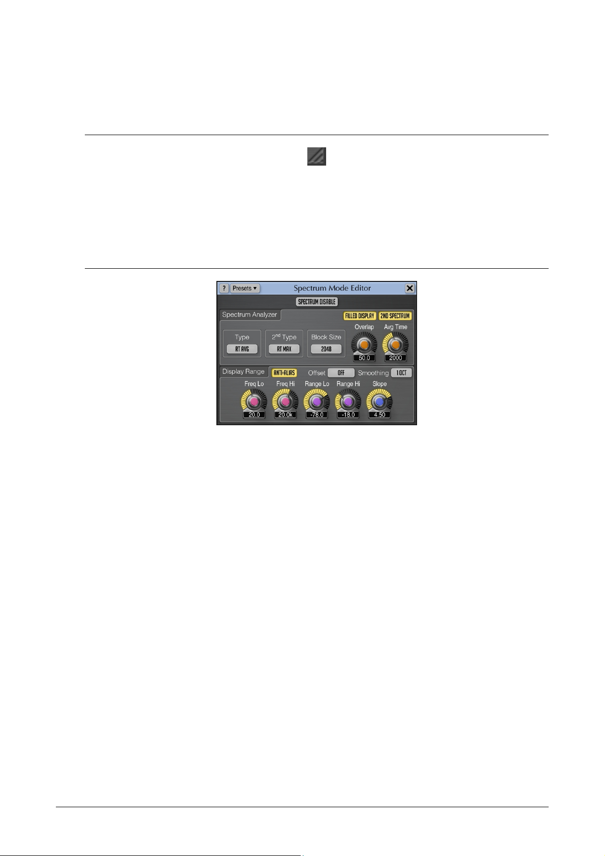
Spectrum Mode Editor
The “Spectrum Disable” switch completely disables spectrum analysis function of the
plug-in.
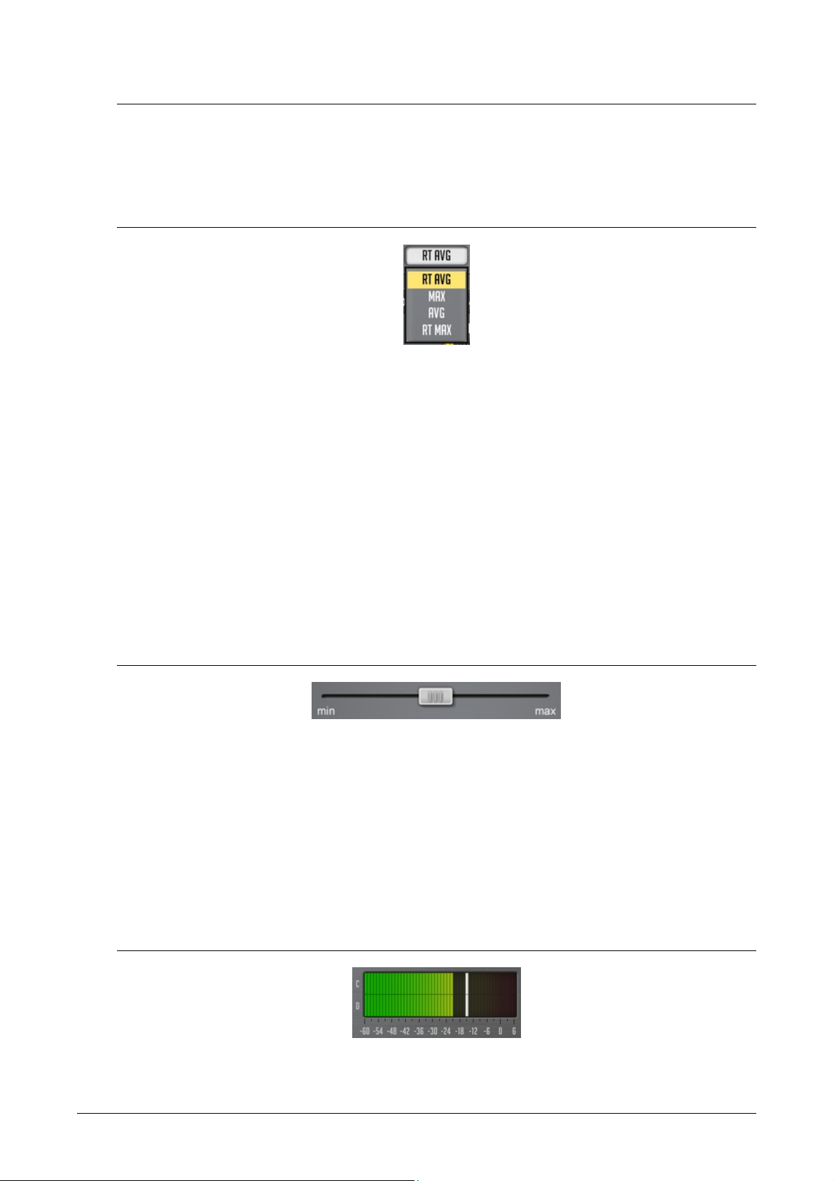
The “Type” selector specifies which spectrum analysis type should be used. The “RT
Avg” mode engages the real-time spectrum averaging analysis. This type of analysis
produces averaged spectrum over the specified period specified by the “Avg Time”
parameter. The “Max” type of analysis produces cumulative maximum power
spectrum. If you need an “infinite” peak hold, please use the “Max” analysis type.
The “Avg” type of analysis produces cumulative average power spectrum. The “RT
Max” produces real-time maximum spectrum with spectrum fall-off (for better
spectrum maximum estimate it is suggested to use a higher “Overlap” setting). The
“RT Sigma” produces sigma spectrum which shows how much dynamic certain
spectral areas are. The best way to use the “RT Sigma” mode is together with the “RT
Avg” mode. This way you can easily see spectral areas that are more or less dynamic:
the areas that are highly dynamic will be displayed above the “RT Avg” spectrum, the
less dynamic areas will be displayed below it.
The “Filled Display” switch enables additional semi-transparent filling of the
spectrum area.
The “2nd Spectrum” switch enables the secondary spectrum curve which is displayed
in a darker color. The “2nd Type” selector selects analysis type to use for the
secondary spectrum. For example, by setting the “2nd Type” to “RT Max” and “Type”
to “RT Avg” you may see the average and maximum spectrums simultaneously. Note
that the secondary spectrum uses the same “Block Size” and “Avg Time” parameters
as the primary spectrum.
Copyright © 2007-2018 Aleksey Vaneev
Page 16

Voxengo Primary User Guide
16
The "Block Size" selector specifies the block size of the FFT (fast Fourier transform)
spectrum analyzer. Higher block sizes provide more resolution in the lower
frequency range, but decrease time coherence (time precision) in the higher
frequency range – the higher frequency information becomes over-averaged. Also, at
higher “Block Size” settings the spectrum is refreshed less frequently. This can be
mostly fixed by increasing the “Overlap” parameter which increases spectrum refresh
frequency.
Note that you will generally need to increase the “Block Size” when working at
increasingly higher sample rates since the specified “Block Size” setting is used over
the full spectral bandwidth, and so at higher sample rates analyzer’s resolution in the
visible frequency range will be lower for the given “Block Size” setting.
If you would like to measure frequency of a low-frequency sound (e.g. bass drum or
bass guitar) precisely you should use a higher “Block Size” parameter value along
with a higher “Overlap” parameter value. You may naturally need to set a higher
“Overlap” value with a higher “Block Size” value because otherwise the spectrum
display will be blinking.
In order to avoid clicks and glitches in playback when using high “Block Size” values
you may need to increase the audio buffer size in your audio host application.
The “Overlap” parameter controls the time overlap between the adjacent FFT
spectrum analysis blocks. E.g. 80% means the block currently being calculated is
overlapped with the previously calculated block by 80% in time. Higher overlap
values allow spectrum to be updated more frequently at the expense of a higher CPU
load.
The “Avg Time” parameter specifies averaging (fall-off) time (in milliseconds) used
when the “RT Avg” or “RT Max” analysis is active. This value specifies time it takes
spectrum level to fall down by 20 dB.
The “Smoothing” parameter selects spectrum smoothing function’s resolution in
octaves. Note that smoothing being solely visual produces 6 dB per octave drop when
stationary sine-wave signals are analyzed. E.g. even if the signal consists of 2 sinewaves (1 kHz and 2 kHz) of equal peak amplitude, the 2 kHz sine-wave will look like
it is 6 dB quieter. This happens because fast Fourier transform produces a narrower
spectrum for high-frequency stationary signals in comparison to low-frequency
stationary signals. This drop does not practically appear when non-stationary
(musical) signals are being analyzed.
The “Offset” parameter selects spectrum’s offsetting. The “Normalize” offset mode
normalizes all spectrums so that the loudest frequencies are displayed on top. The
“Center” offset mode centers all spectrums: this mode can be especially useful when
comparing several spectrums as it removes the overall loudness factor from the
comparison.
The “Freq Low” and “Freq High” parameters (if they are available in a given plug-in)
specify the accessible (and visible) frequency range (in Hertz) of the spectrum view.
The “Range Low” and “Range High” parameters select accessible (and visible)
spectrum power range (in decibel).
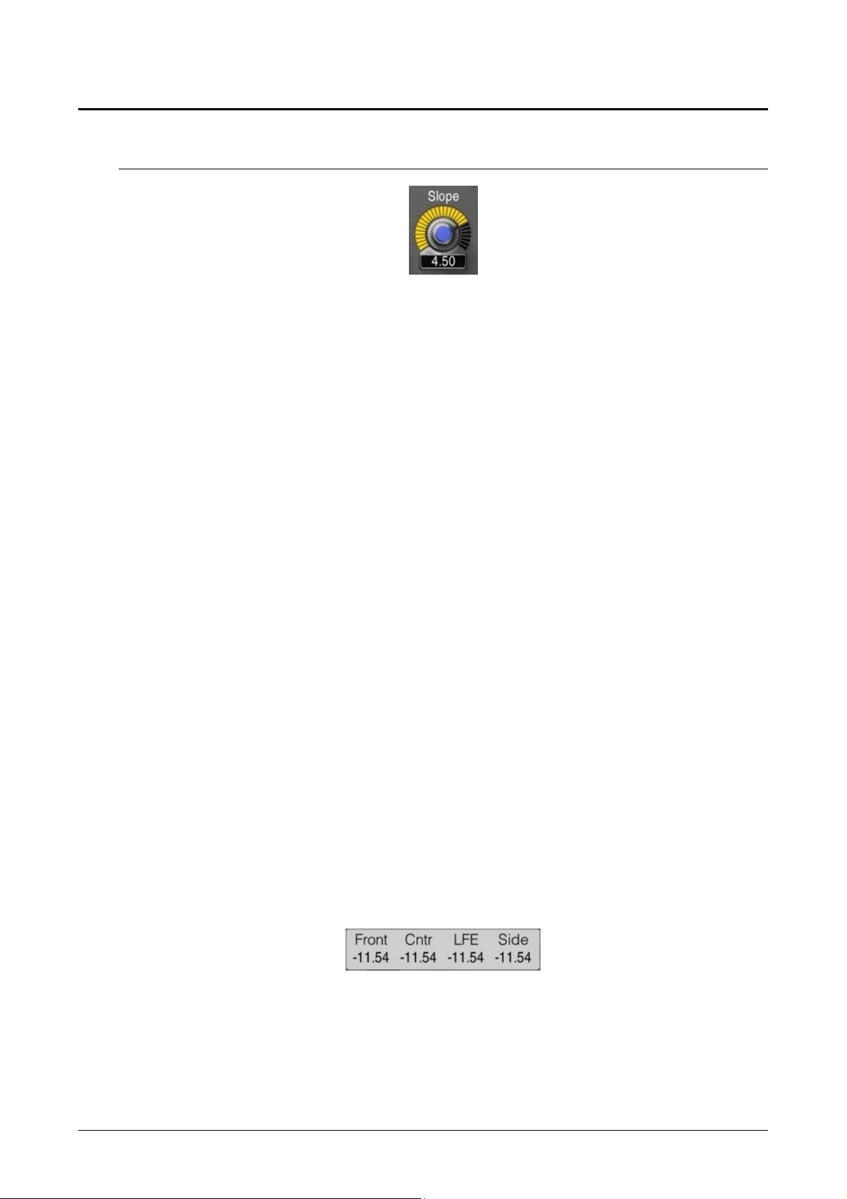
The "Slope" selector (which is defined in dB per octave) allows you to adjust spectrum
analyzer display’s slope around 1kHz. Skewing the spectrum can be useful because
higher frequencies usually have weaker power in comparison to the lower
Copyright © 2007-2018 Aleksey Vaneev
Page 17

Voxengo Primary User Guide
17
frequencies. By choosing an appropriate spectrum slope, you can compensate for this
fact and make the spectrum plot look more convenient and meaningful.
The “Anti-Alias” switch enables anti-aliased spectrum curve drawing.
DC Filter Mode Editor
This window allows you to fine-tune the DC filter, and create user presets if required.
DC filter (also known as high-pass filter) is applied after all processing stages, and is
used for removing ultra low-frequency content introduced by plug-in’s processing
modules.
The “DC Filter Enable” switch enables DC filtering stage.
The “Freq” parameter specifies the corner frequency of the DC (high-pass) filter.
The type selector specifies DC filter type. The “Steep” filter types offer a steeper
cutoff frequency response, but a higher phase shift. The “Soft” filter types have a
smoother cutoff frequency response and a lower overall phase shift. The number
before the filter type denotes dB/octave roll-off of the filter (e.g. “-18 Soft” means “-18
dB/octave soft filter”).
Note that DC removal filter induces phase shift and thus may affect sonic character of
a sound material. For best results you may specify DC filter frequency as low as
possible and use non-steep filter types (preferably, -6 dB/octave one). Due to its
phase shifting, the DC filter may be also used creatively to adjust the sonic character
of a sound material in the low-frequency region.
Static Spectrums Editor
Some Voxengo equalizer plug-ins feature static spectrums display that can be
controlled via the editor window shown above. You may select the display name of
the spectrum slot, its color, the shift in decibel of the static spectrum on the control
Copyright © 2007-2018 Aleksey Vaneev
Page 18

Voxengo Primary User Guide
18
surface. The static spectrum can be shown or hidden via the visibility check box. The
shift in decibel can be used for a more convenient placing of the static spectrum on
the screen, and it does not affect the shape of the spectrum.
The “Take” and “Take 2nd” buttons take a snapshot of the primary or secondary
spectrum, respectively. The static spectrums you “take” use spectrum parameters
specified in the “Spectrum Mode Editor”. If after pressing any of these buttons no
spectrum is taken, it means that no spectrum is currently available – you either have
to configure the spectrum mode or start the audio playback first. Before taking a
spectrum, please do not forget to choose an appropriate spectrum analysis type via
the “Spectrum Mode Editor” – usually “Avg” or “Max” (or you may simply load the
factory “Average” or “Avg+Max” spectrum mode preset), and analyze long enough so
that spectrum becomes general enough. When analyzing a song, it may be a good
idea to store separate spectrums for verse, chorus and bridge parts as they may have
distinctively differing spectral balance.
The “Predef” button allows you to load one of the predefined static spectrums.
The “Load” and “Save” buttons allow you to load and save the spectrum file into the
static spectrum slot. The files have the “.csf” (compressed spectrum file) file
extension. Note that you can also load spectrum from a Wave PCM sound file (“.wav”
file extension).
The “x” button resets the spectrum in the selected slot.
When a spectrum is available in the static spectrum slot, the spectrum’s parameters
are also displayed. They correspond to parameters that were configured via the
“Spectrum Mode Editor” when the spectrum was taken.
The “Filled Display” switch enables display of all static spectrums in a filled form.
The “Spectrum Mode” selector in this window was added for a quick access to
spectrum mode presets: it is equivalent to the spectrum mode selector and editor
located on the main plug-in window.
Copyright © 2007-2018 Aleksey Vaneev
Page 19

Voxengo Primary User Guide
19
Undo/Redo
Voxengo plug-ins offer a convenient way of managing changes you apply to the plugin’s state. When you apply a change to any control, its previous and new values are
stored in the special “change log” which you can then use to “unwind” and “rewind”
any previously made changes. This way you can be sure that no single unwanted or
occasional change you do affects the state of the plug-in in a wrong way.
Undo/redo control consists of three buttons: the “Undo”, the “History” and the
“Redo”:
The “Undo” button allows you to un-do changes made to the plug-in’s state.
The “Redo” button allows you to re-do changes that were already un-done via the
“History” or “Undo” buttons.
The “History” button opens change log (history) that lists all changes made to the
plug-in’s state in the order you have made these changes before. You can re-do and
un-do changes to any level of depth, instantly. Change log keeps track of last 32
changes you have made. Note that a parameter change is logged with group name
placed in parentheses (e.g. “Gain (Ls) change”).
Copyright © 2007-2018 Aleksey Vaneev
Page 20
Voxengo Primary User Guide
20
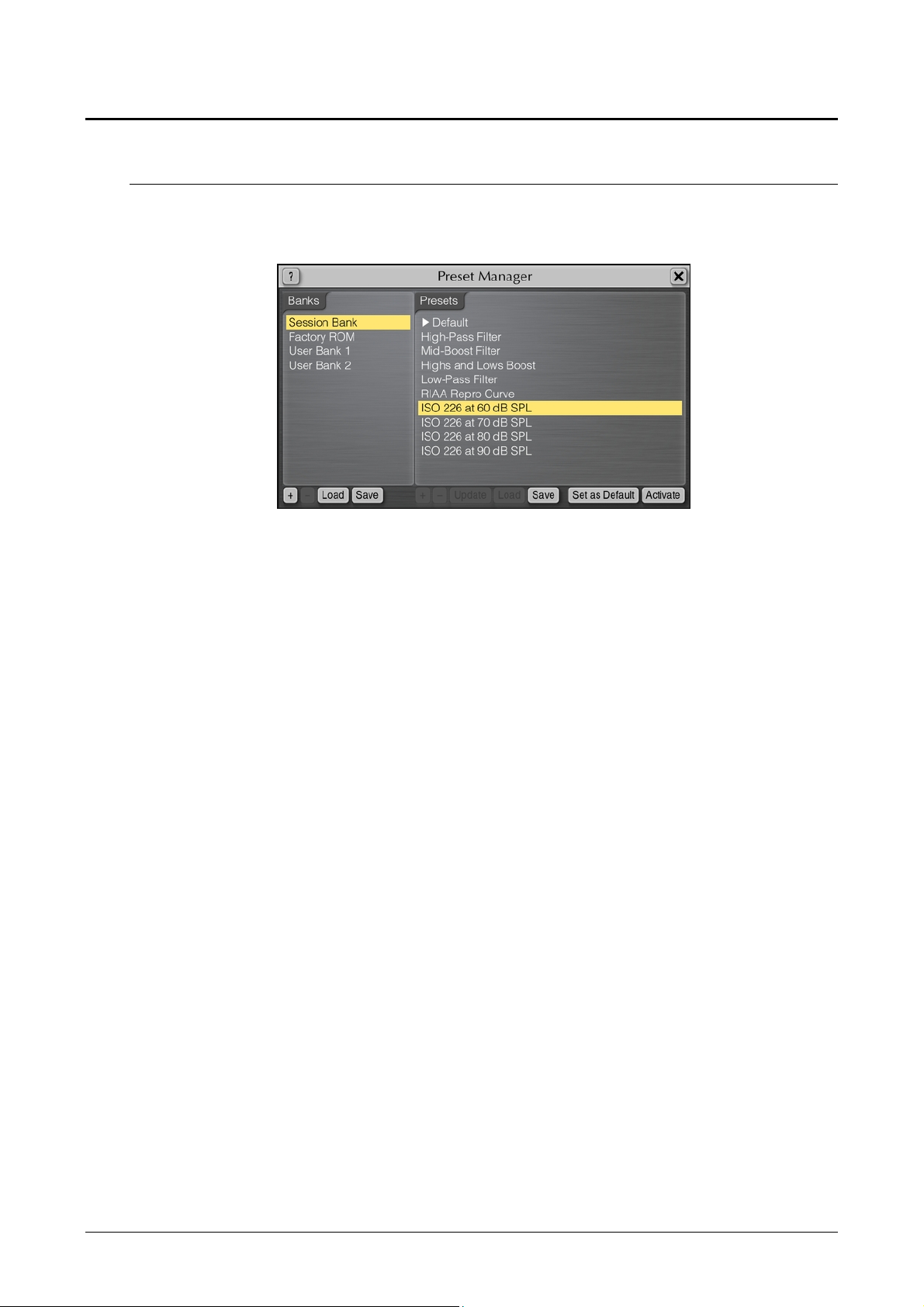
Preset Manager
Main Preset Manager
Every Voxengo audio plug-in features the main preset manager which you can use to
store plug-in state presets you define.
Presets in the main preset manager are shared among all instances of the same
Voxengo plug-in. All presets within the main preset manager are stored in user
preset banks. Beside user preset banks two special banks exist: the “Session Bank”
and “Factory ROM” bank.
The “Session Bank” contains “programs” rather than presets. Each program in the
“Session Bank” contains its own undo/redo change log, meaning that when you
switch the program in the “Session Bank” you are also switching the undo/redo
context. A currently selected program is specified by the “right allow” symbol. The
“Session Bank” lists programs that “mirror” programs of the VST audio host
application (in AudioUnit-compatible applications this bank can be used as a
temporary preset palette). When you are activating a program in the “Session Bank”
you are actually switching the current program in the VST audio host application (in
AudioUnit-compatible applications program switch in the “Session Bank” is similar
to a plain preset switching).
The “Factory ROM” bank lists presets that were pre-programmed by the plug-in's
producer. These presets cannot be changed, but can be activated. The “Factory
ROM” bank is also loaded into the “Session Bank” every time a new instance of the
plug-in is created in the audio host application.
The main preset manager contains the following control buttons:
The “+”, “–”, “Load” and “Save” buttons allow you to add and remove the bank or
preset, and load and save the bank or preset to and from a disk file. Right-clicking
the “+” button inserts preset into the current list position rather than to the end of the
list if the left mouse button is clicked. The “U” button allows you to update a
currently selected preset by storing the current plug-in state in it.
Please note that Voxengo plug-ins use a proprietary format to store presets and
preset banks. We suggest that you add a comprehensive name prefix to bank and
preset files so that you would not mix up presets created in different Voxengo plugins. During a save operation, the plug-in will offer you a default name prefix
Copyright © 2007-2018 Aleksey Vaneev
Page 21
Voxengo Primary User Guide
21
automatically. Voxengo plug-in preset files possess the “.cpf” file extension while
preset bank files possess the “.cbf” file extension.
The “Set as Default” button allows you to designate a selected preset to become the
default preset. If you want to restore the original default preset you should press the
“Set as Default” button on the “Default” preset in the “Factory ROM” preset bank.
Double-clicking on a preset name loads the specified preset state. The same does the
“Activate” button. A preset load operation can be undone by pressing the “Undo”
button.
To change a name of the preset or bank you should at first select the required item
and then after a small delay click the item again. Please do not mix this operation
with a double-click which activates a selected preset.
Local Preset Managers
Voxengo plug-ins also feature so called “local” preset managers: for example, the one
available in the “Channel Routing” window. These preset managers do not possess
preset banks, and are not related to the main preset manager: they work
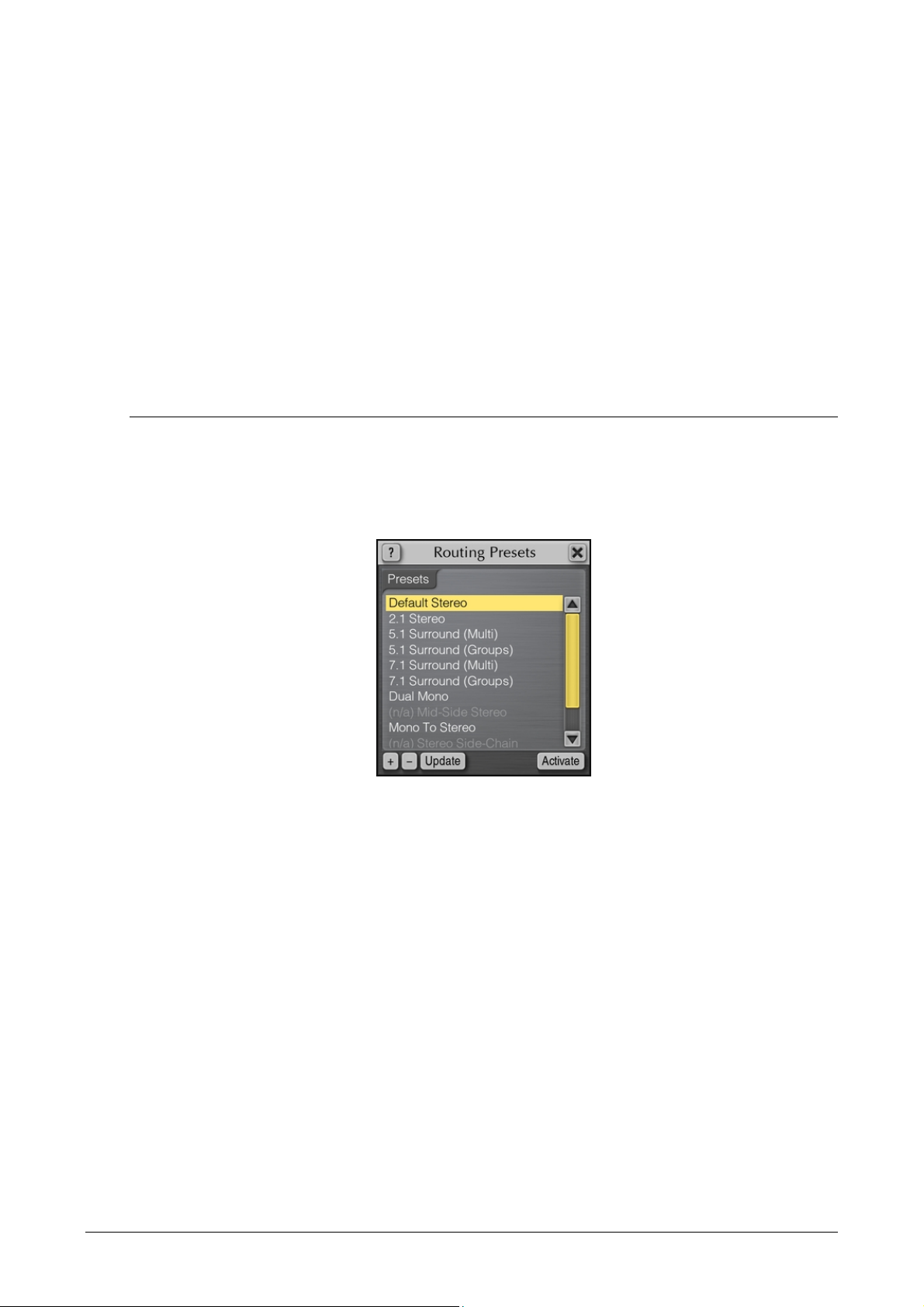
independently from the main preset manager.
Local preset managers usually manage presets for a specific module of a specific
Voxengo plug-in. The “Update” button can be used to quickly update selected preset
to the current state.
Presets available in the “Routing Presets” local preset manager are globally accessible
to Voxengo plug-ins of all kinds. These presets greatly minimize routine adjustments
you usually need to perform after creating a new plug-in instance in your audio host
application. Routing presets that are not compatible with the current plug-in are
shown grayed out with the “(n/a)” prefix.
Copyright © 2007-2018 Aleksey Vaneev
Page 22
Voxengo Primary User Guide
22
Channel Routing Window
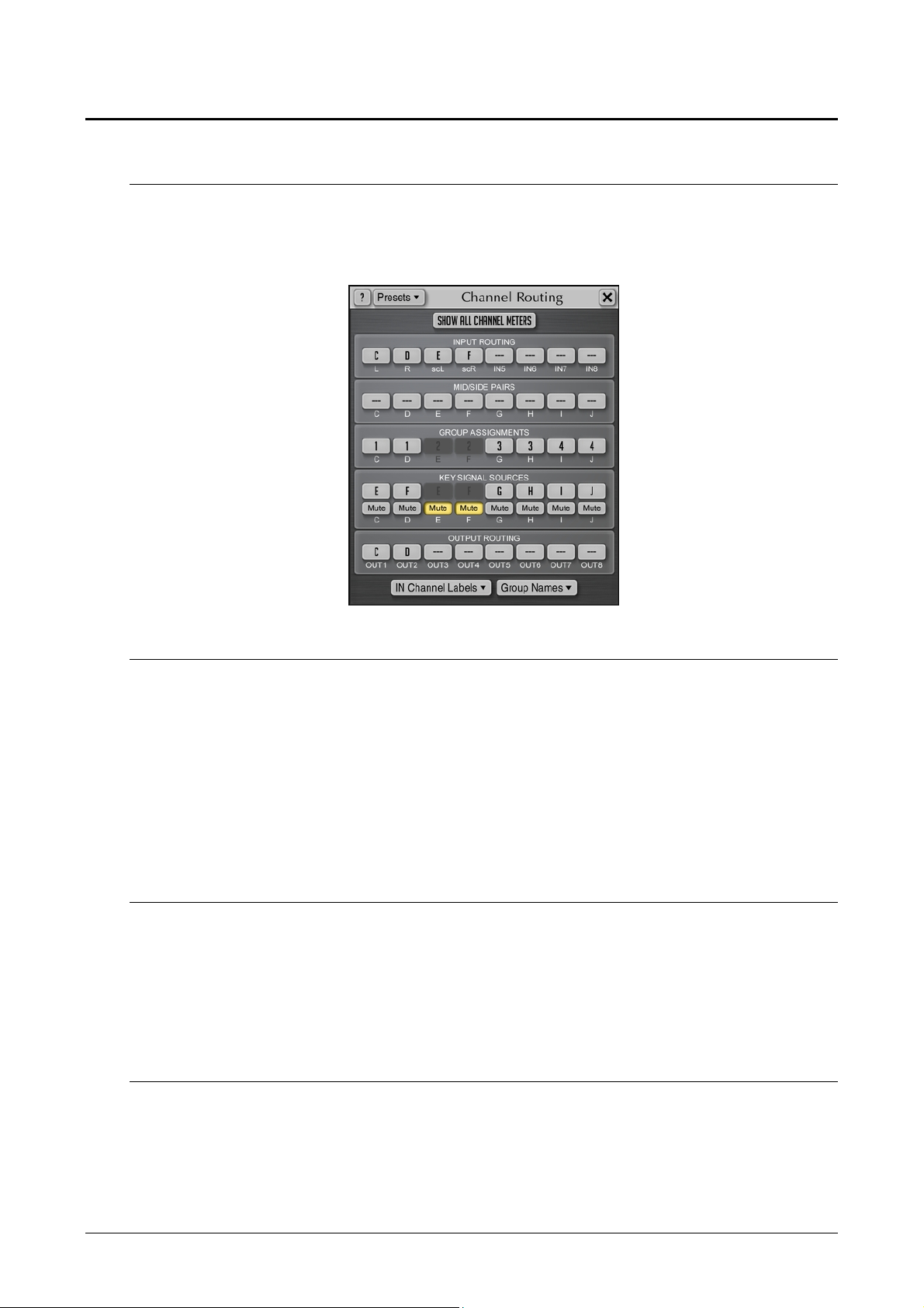
Layout
The “Channel Routing” window consists of a set of selection buttons assembled in the
following groups: the “Input Routing”, the “Mid-Side Pairs”, the “Group
Assignments”, the “Key Signal Sources” and the “Output Routing”:
Input and Output Routing Selection
These groups of buttons allow you to route external plug-in inputs to internal plug-in
channels and vice versa: to route internal plug-in channels to external plug-in
outputs. A plug-in has a pre-defined number of internal channels while the number
of input and output channels may vary depending on the audio host application’s
track or bus where the plug-in resides. Note that if input routing selector appears
red, it means that this selector refers to a non-existent input channel: you may correct
this warning by selecting an existing channel. External side-chain inputs are denoted
by parenthesized labels: for example, “(IN3)”, “(IN4)”.
Show All Channel Meters
This option enables displaying of all channel meters and statistics counters regardless
of the currently selected channel group. When this option is not enabled, only meters
belonging to the currently selected channel group will be shown. Enabling this option
is useful when you are using dual mono or mid-side processing: this option will allow
you to see channel meters for left and right, or mid and side channels together.
Mid-Side Pairs Selection
These buttons (if available in a particular plug-in) allow you to assign internal
channels to mid-side encoding/decoding pairs. The mid-side encoding is a widespread technique that allows you to process stereo signal’s middle (center) and side
(spatial) information independently of each other thus offering a great deal of control
over that signal’s stereophony. Mid-side encoding works with paired channels only
Copyright © 2007-2018 Aleksey Vaneev
Page 23

Voxengo Primary User Guide
23
and thus requires two channels to be assigned to the same mid-side pair. An input
signal is mid-side encoded before it is processed by the plug-in, and decoded
afterwards before it is routed to an output of the plug-in.
Channel Group Assignments
The plug-in allows you to assign its internal audio channels to logical groups of
channels. Each group with its channels is affected by its own set of parameter values
(it can be an EQ shape, a gain factor, an overdrive setting, etc.) The current channel
group is selected via the channel group selector.
Individual audio channels can be attached to different channel groups. For example,
this allows you to have individual EQ settings for channel 1 and for channel 2,
separately. To achieve this you may simply assign channel 1 to group 1, and channel 2
to group 2.
In a surround setup you may assign left and right channels to group 1, and surround
channels to group 2, and apply an EQ shape to them independently from each other.
Each plug-in audio channel can be assigned to a single channel group only. Channel
grouping also affects channel-linking in case of dynamics processing and other
processes that estimate signal loudness envelope: channels assigned to the same
group will be linked during processing and signal loudness estimation. The mode of
such linking (max of all, average of all, etc.) may be specified with an additional plugin control, if available.
Key Signal Sources
This set of buttons (if available in a particular plug-in) allows you to assign key signal
sources to all internal channels. For example, instead of using channel’s “A” self
signal to trigger processing performed on this channel you may assign channel “B” to
trigger processing performed on the channel “A”. Key signal sources are usually used
in dynamics processing plug-ins. The technique when any particular channel is used
as a “key” for another channel is called ducking: “key” channel “ducks” another
channel. E.g. bass guitar track may be “ducked” by a drum track if necessary.
If some internal channel is only used as key signal source (e.g. this channel is an
external side-chain signal), this channel can be “muted”: in such case this channel
will not be processed and sent to the output together with channels that were not
muted. Such “muted” channel will be available to plug-in’s internal algorithms only.
Please note that external side-chain sources are always represented by individual
input channels in the plug-in. While audio host applications that support AudioUnits
usually offer a convenient one-click “side-chain” input selection for the plug-in, these
side-chain inputs are shown as additional input channels in the “Channel Routing”
window of the plug-in, with their names parenthesized: e.g. “(IN3)”. These channels
should be routed in the same way as ordinary channels are routed, including setting
up required key signal sources assignments. Even though such way of setting up
external side-chain does look somehow complicated, it offers a very deep control over
side-chaining: for example, it allows you to perform mid-side encoding of the sidechain input before it is used for keying; another useful feature is that you can swap
channels of the side-chain input effortlessly.
Copyright © 2007-2018 Aleksey Vaneev
Page 24

Voxengo Primary User Guide
24
In Channel Labels
By pressing this button you can open the channel label assignment popup window.
You can give individual names to input channels in order to simplify a further
channel routing setup understanding. Channel names you provide are also displayed
on the user interface to inform you about channels that are currently being adjusted
by the plug-in’s controls.
You can also import channel labels from the audio host application by pressing the
“Import labels from host” button. However, not all audio host applications provide
distinctive input channel names: in that case entering your own names manually is
the only existing option (Mac OS X AudioUnits do not provide input channel names).
Group Names
This button opens the group name assignment popup window. You may assign
names to channel groups for easiness of channel group selection.
Routing Presets
The “Routing Presets” button opens a local preset list that covers settings present in
the “Channel Routing” window, including channel labels. These presets are shared
among Voxengo plug-ins of all types: note that due to this fact a particular preset (e.g.
the one that uses mid-side pairs or external side-chain assignment) may not be
applicable to a specific plug-in where the used feature is unavailable (not all plug-ins
possess mid-side processing and external side-chain) – in this case such preset will be
shown grayed out, with the “(n/a)” prefix.
Copyright © 2007-2018 Aleksey Vaneev
Page 25

Voxengo Primary User Guide
25
Channel Group Selector
Almost every Voxengo plug-in features the channel group selector which allows you
to select the channel group for which parameters are currently being edited or
monitored.
This selector, when pressed, displays a selection of channel group names (indices, by
default). Only groups actually assigned to the internal channels in the Channel
Routing window are shown. You may use this control to switch between channel
groups.
The “Solo” switch allows you to solo channels that belong to the currently selected
group. This can be useful if you want to focus listening on group’s channels only (for
example, in “Mid-Side Stereo” routing setup). The state of the “Solo” switch is not
saved between project sessions, and is not restored to its previously enabled state
when the project is reloaded.
The “Copy to” button allows you to copy parameter settings defined for the current
channel group, to another channel group.
Channel Group List
A Voxengo plug-in also presents a list of input channels being routed to a currently
selected channel group. This list is interconnected with the “Channel Routing”
window, and displays routing settings defined by it. This list contains names of input
channels, comma delimited. Internal channel name (“A”, “B”, “C”, etc.) that accepts
the corresponding input channel is displayed in a superscript style (these internal
channel names are also displayed on the level meters). If more than one input
channel is routed to the same internal channel, the sum is displayed in the form
“(IN1+IN2)”. Additionally, when the internal channel is assigned to a mid/side
group, its input channels are taken into parentheses with the “m” (mid) or “s” (side)
prefix: “s(IN1 & IN2)” which means “side part of the mid/side pair consisting of IN1
and IN2 input channels”.
When a plug-in supports side-chain, any side-chain assignments are displayed with a
special postfix: “:sc()”. For example, “L:sc(scL)” means that the input channel “L” is
affected by the side-chain signal from the input channel “scL”.
Copyright © 2007-2018 Aleksey Vaneev
Page 26

Voxengo Primary User Guide
26
Plug-In Settings for a Specific Plug-In
Voxengo plug-ins feature a set of settings that affect instances of the same plug-in
only: they do not affect the same settings of other Voxengo plug-in types. This is
convenient since this way you can select different color schemes for different plug-in
types (for example, a Voxengo compressor may be colored in reds while a Voxengo
equalizer may be colored in grays). The same applies to the user interface scale and
the hints display switch: for example, if you have not still mastered a specific Voxengo
plug-in you may leave the hints for this plug-in visible while you may disable the
hints for a Voxengo plug-in you know well.
Color Scheme
The color scheme selector consists of several small preview icons that show possible
color scheme selections. You may press a desired icon to change the color scheme of
all instances of the plug-in. Color scheme switches immediately in all open plug-in
instances, and instances that will be opened later.
User Interface Scale
By using this setting you may adjust the visual scale of the plug-in. For example, if
your screen resolution is very high (1920 x 1200 or more) you may enable the largest
scale. On the other hand, if your screen resolution is low (1024 x 768) or you want to
have many plug-in instances visible on the screen, having a smaller user interface size
can be beneficial: in that case you may select the 80% scale. Note that the visual scale
switch requires reopening of the plug-in window. The “Scale to Screen” switch on
Windows enables automatic scaling based on primary screen resolution: this switch is
useful if you have an ultra high-resolution display (4K and above).
Min Infrastructure
This switch enables the “minimal infrastructure” look of the user interface. Such look
reduces the visual complexity of the user interface by hiding several infrastructural
elements like the instance name box, oversampling selector, bypass switch, plug-in's
name and version labels on top, and the group selector on the bottom of the user
interface.
Show Groups Bar
This switch (if available in a particular plugin) enables display of a group selection
bar at the bottom of the user interface.
Oversampling
This selector, if available in a particular plug-in, allows you to choose the type of
oversampling filter to use. Oversampling is discussed in the topic “Main Control
Buttons – Oversampling Selector” above. The “Min-Phase” option selects minimumphase oversampling filter which is easy on CPU and does not add a considerable
processing latency. The “Lin-Phase” option selects linear-phase oversampling filter
Copyright © 2007-2018 Aleksey Vaneev
Page 27

Voxengo Primary User Guide
27
which is CPU-intensive and adds around 11 milliseconds of processing latency. At the
same time, the linear-phase filter adds no phase coloration to the sound material
while the minimum-phase filter adds such coloration (which is, however, mostly
unnoticeable).
It is important to note that while the minimum-phase oversampling does not change
the subjective quality of the sound when you monitor it alone, it may seriously change
the sound when you mix “min-phase” oversampled sound together with nonoversampled sound, especially if the sounds are correlated to each other (e.g. mix of
several drum microphone tracks). If you have faced such problem you should either
disable oversampling completely, or enable it on all tracks you are mixing, or engage
the “Lin-Phase” oversampling in all Voxengo plug-ins you use.
Note that in VST audio host applications this switch should be adjusted with care.
While with most hosts a simple playback restart is enough for the change to take
place, in some hosts it may require full application restart and plug-in rescan to
change the processing latency. Not doing so may make tracks where the plug-in is
used go out of sync. The plug-in window will show the red “Latency Changed” label if
playback restart (or application restart, or current project reload) is required due to
the processing latency change that occurred.
Meter “Density Mode”
This checkbox enables “density” metering mode. In this mode you can see levels a
signal stays at often. By examining the range of levels a signal stays at you may draw
conclusions about effective dynamic range of the sound material. Note that signal
level estimation in the “density” mode is affected by the configured meter’s
integration and release times. Configured meter’s peak level hold time affects time
duration a specific signal level registers on the meter in this mode.
Meter Integration Time
This parameter affects signal level integration time (in milliseconds) of all level
meters (this value reflects time it takes for a signal level to fall down by 20 dB, or
raise up from any steady level to another steady level). Note that this setting does not
affect peak level registered on the level meters, but directly affects the visible
difference between the peak and RMS signal levels when a musical signal is metered.
If you would like to measure the RMS loudness of the lower frequencies precisely you
have to use a higher integration time, at least 50 milliseconds. With lower integration
times (e.g. 2 milliseconds), the level meter actually measures peak levels, not RMS, in
the lower frequency range, but the RMS level of the higher frequencies (above 1kHz)
is measured correctly. So, you have to choose a balance between the precision at the
lower frequencies and level meter’s rise speed.
Meter Release Time
This parameter changes level meter’s release time (in milliseconds), and is also
known as level meter’s “ballistics”. This is the time it takes a signal to fall down by 20
dB. If you need 20 dB per second fall-off, the release time should be set to 1000
milliseconds.
Copyright © 2007-2018 Aleksey Vaneev
Page 28

Voxengo Primary User Guide
28
Meter Peak Level Hold Time
This parameter adjust time (in milliseconds) a registered 1-sample wide peak level
stays on the level meter unchanged. Also affects level meter display in the “density”
mode.
Copyright © 2007-2018 Aleksey Vaneev
Page 29

Voxengo Primary User Guide
29
Global Voxengo Software Settings
Voxengo plug-ins also feature global settings that are shared among all Voxengo
software types. These settings mainly customize your interaction with various
controls: mouse wheel precision, knob drag precision, etc.
Auto Oversampling Level
This option selects oversampling level used by Voxengo plug-ins when the “Auto”
oversampling option is selected. This option selects maximal oversampling level
used. The actual used level may be lower depending on the working sample rate (the
higher the working sample rate the lower the auto-selected oversampling is). Change
takes effect only after the audio host application is fully reloaded.
Note that auto oversampling is engaged only during project bouncing stage. Some
audio host applications do not report this stage to the plug-in: in this case the auto
oversampling setting will not work.
Mouse Wheel Precision
This setting affects a precision of the mouse wheel – the higher the precision the finer
the control change that can be done with the mouse wheel.
Shift Key Precision
This setting affects a control change precision when the Shift key modifier is pressed
during the drag of any control with the mouse.
Drag Precision
This setting affects precision of mouse drag operations. This setting applies to knobs,
level meters and readouts only.
Show Preset Selector
This switch displays the quick preset selector instead of instance name entry field.
This option is applicable only to plugins that have instance name entry field.
Show Knob Labels
This switch allows you to enable or disable numeric labels that appear around the
knob when you are hovering the mouse cursor over it.
Tablet Mode
This switch enables “tablet” mode allowing you to control Voxengo audio plug-ins
with a pen tablet. This mode can be also used if you are operating plug-ins via remote
desktop software. If this mode is not enabled, the mouse cursor will be hidden on
every mouse dragging operation.
Copyright © 2007-2018 Aleksey Vaneev
Page 30

Voxengo Primary User Guide
30
Show Virtual Keyboard
When this switch is enabled, value entry will be accompanied with a popup window
showing the “virtual keyboard” you can use instead of your real keyboard to enter
various values (numeric and textual). Virtual keyboard is especially useful when the
audio host application “blocks” certain keys from reaching plug-in’s user interface.
Remember Window Positions
This switch allows you to enable or disable saving of window’s position when it is
reopened after closing. Window’s position is saved relative to the parent window.
Enable Mouse Wheel On Lists
This switch enables selection of list options via mouse wheel. This option is
suggested to be disabled if mouse pad is in use or mouse wheel’s movements are not
discrete.
Curve Drag Adds Points
This switch enables automatic control point addition when EQ or envelope curves is
dragged. Otherwise mouse double-click should be used to add points.
Radial Knob Mode
This option enables radial operation mode of the knob. You may disable this mode if
you usually use linear knob mode only.
Control Surface Crosshair
This option enables crosshair display in the plug-ins on their “control surface” areas
– e.g. equalizer, spectrum analyzer.
Show All Filter Shapes
In equalizers, this switch enables display of shapes of all active filters together with
the shape of the currently selected filter.
Show Colorized Filter Shapes
In equalizers, this switch enables display of filters in an automatically selected color.
Do Not Show Latency Changes
This switch can be used to disable the “Latency Changed” warning message
completely if it becomes annoying (some audio host applications do not update
latency when plug-in requests it).
Copyright © 2007-2018 Aleksey Vaneev
Page 31

Voxengo Primary User Guide
31
Anti-Denormal Noise
This switch enables insertion of anti-denormalization noise on plug-ins’ inputs. This
noise has loudness of -220 dBFS – well below the audible dynamic range. If you are
using Voxengo plug-ins in an audio host application that applies such noise
automatically you may disable this switch to preserve some CPU resource. Without
this anti-denormal noise the filters and oversampling of the plug-in may overload
CPU when silence signal is being processed.
VST 2 Function Sync
This switch enables internal VST 2 function synchronization that solves crash
problems in some hosts at the expense of minor added CPU load. For example,
Tracktion 3.0.4.8 may call plug-in's “suspend” function together with the audio
processing function: this is, of course, an incorrect behavior which leads to a crash.
You may enable this switch to ensure no interfering functions will be called
simultaneously.
Beside Tracktion, this switch is required to be enabled in Samplitude to resolve
crashes and slowdowns.
No Multi-Channel Operation
This switch forces stereo and mono (no multi-channel) operation in Voxengo plugins. Enable this switch if you are using VST 2 audio host applications that do not
support multi-channel VST plug-ins correctly. To take effect, this switch requires
audio host application restart.
Visual Settings
Latest Voxengo software features a set of visual settings that allow you to subtly
customize the look of the plug-ins. These settings are:
1. Flat Panels – when enabled, all buttons and panels will look flat, without gradient
fill.
2. Spotlight – enables a wide light area that looks like a trace of spotlight.
3. Textures – enables texturing of the panels.
4. Shadows – enables shadows on visual elements.
5. Flat Level Meters – enables the “flat”, non-blocky look of the level meters.
6. Frames Per Second – specifies user interface refresh frequency.
Copyright © 2007-2018 Aleksey Vaneev
Page 32

Voxengo Primary User Guide
32
Plug-In Files’ Locations
Any Voxengo software title is bundled in a separate archive or installation file for
every target platform. These archives contain document files, a license agreement, a
change history log and a plug-in or application itself in the form of the dynamic link
library (DLL) or the component file, or executable file for any given target computer
platform.
In order to be able to instantiate the plug-in in an audio host application you should
put the DLL (component) file into the correct file folder that corresponds to the
“plug-ins path” specified in that audio host application. It is suggested that you put
the DLL (component) file into the “Voxengo” subfolder within the plug-in folder, for
easier searching.
While it is mandatory to read and agree to the supplied license agreement before
using the plug-in, you may for your convenience put the DLL (component) file
separately from its accompanying files, including the license agreement file.
However, as license agreement explicitly mentions, the DLL (component) file cannot
be re-distributed to other persons or companies/entities separately. You may store
the DLL (component) file separately from its accompanying files for your own
archival and storage convenience purposes only.
During its operation, the software also creates settings files where it stores global and
per software title settings, including presets. On Windows systems the data files
created by Voxengo software reside in the hidden “\Users\<UserName>\ Application
Data\Voxengo\” folder (on Windows systems prior to Vista the root folder is called
the “\Documents and Settings\” instead of “\Users\”); on Mac OS X systems the data
files reside in the “/Users/<UserName>/Library/Preferences/Voxengo/” folder. You
may safely remove, copy and replace these files, including the whole “Voxengo”
subfolder. All Voxengo settings and presets are available to the specific user of the
computer only.
Copyright © 2007-2018 Aleksey Vaneev
Page 33

Voxengo Primary User Guide
33
Additional Information
Selecting Best Audio Block Size
The most efficient audio card block size (latency) to work with Voxengo plug-ins is
512 samples (plug-in's internal processing overhead may become considerable at low
latencies such as 64 samples – various plug-ins may require 30-100% more CPU time
to process at such low latency).
64-Bit Audio Processing
Plug-in conforms to the VST specification version 2.4, and so it is able to interface
with audio host applications in full 64-bit floating point resolution (if supported by
the audio host application).
AudioUnit version of plug-in is technically able to process 64-bit floating point audio
data.
Plug-In Registration/Authorization
Commercial Voxengo software titles should be registered (authorized) before you can
use them in non-demo mode. Each commercial software title in its Settings window
contains a special area where user registration/authorization details can be entered.
Please use the standard copy&paste functions to ensure a correct product key entry
(you may right-click the product key entry field to paste the key). User name is not
required for entry. When details were entered correctly, you will see the “Registered
to” text in the Settings window: in this case plug-in is working in a non-demo mode.
CPU Load Measurement Notice
Before judging the plug-in’s CPU load performance please make sure you understand
that on multi-processor (multi-core) computers CPU load metering offered by the
audio host application you are using can only be approximate. The reason for this is
the fact that depending on the track configuration of your project, you may get a
varying maximum number of plug-ins that can work at the same time. For example,
if your project consists of only a single track with a long effects sequence, you may
quickly run out of CPU resources while if you are putting these effects on parallel
tracks, the maximum number of effects you can use will double at the least.
Also pay attention to the “Oversampling” setting of the plug-in, because running a
plug-in at 4x oversampling setting is equivalent to running 4 separate plug-ins at 1x
oversampling.
Copyright © 2007-2018 Aleksey Vaneev
Page 34

Voxengo Primary User Guide
34
Knowledge Bit – Correlation
As you probably already know, correlation between two independent signals is
defined in the range between -1.0 and 1.0, inclusive. If correlation is close to 1.0
between any two signals, it can be said that signals are “in-phase” (0 degree phase
difference). If correlation is close to -1.0 the signals are “out of phase” (180 degree
phase difference). Correlation values close to 0.0 usually tell that any two signals
have no correlation and so they may either be 90 degree apart or significantly delayed
relative to each other, or both.
Correlation between two sinusoidal signals is equal to mathematical cosine of the
phase difference between these signals.
Note that while simple sinusoidal stationary (constant) signals require only phase
rotation to change correlation value, musical signals and signals which are complex in
their nature may require time alignment (delaying) as well. Correlation of any signal
with any independent (uncorrelated) noise signal is always 0.0 and cannot be
changed with phase nor time alignment.
Stereo Correlation
Speaking about stereo (two-channel) signals, “acceptable” correlation value range lies
between 0.0 and 1.0. Negative correlation values mean that channels are out of phase
and this usually works problematically – stereo field becomes “unreal” (“surround”)
and causes disorientation. Beside that, out of phase stereo information is not monocompatible and such signal sounds poorly if the listener is not placed on the central
listening axis.
In order to create any useful spacious stereo-image the correlation values close to 0.0
should be used. Also note that an uncorrelated stereo-signal in comparison to a
correlated stereo-signal at an equal peak level usually sounds louder to the listener by
around 1.25 decibel, because uncorrelated channel sound coming from a speaker does
not cancel channel sound coming from another speaker spaced 60-degree apart from
it as much as correlated channel sound cancels it.
Copyright © 2007-2018 Aleksey Vaneev
Page 35

Voxengo Primary User Guide
35
Knowledge Bit – Aligning Microphones
This topic discusses possible ways of achieving a good alignment between several
microphones providing a maximally focused and feature-rich sound. While this topic
is easier perceived from the perspective of Voxengo PHA-979 plug-in user,
information contained herein can be used universally.
When you are placing a couple of microphones to capture a single instrument, this
means you are creating a microphone array consisting of two microphones.
When doing microphone alignment you should always consider only two
microphones and a single sound source at a time. One of the microphones should be
considered as the “master” microphone and its delay, phase and gain should not be
changed. When working with three or more microphones in an array, each additional
microphone should be aligned to the master microphone, one by one, so that only two
microphones are considered at a time.
Each microphone in this array has these basic parameters: distance from the sound
source, delay relative to the master microphone and phase relative to the master
microphone. Relative delay can be negative meaning the sound reaches the
microphone earlier than it reaches the master microphone.
All directed microphones should generally capture a single sound source or otherwise
you may face problems getting all sound sources to sound good when trying to align
microphones, because in such case you will have to make complex decisions to find a
good balance of per-microphone phases and delays.
Alignment Steps
Aligning any given microphone in the array relative to the master microphone
basically consists of three steps: 1) finding an optimal delay; 2) finding an optimal
phase; 3) finding an optimal gain.
First of all, it should be said that microphone delay, phase and gain alignment is
required only if you are capturing the direct sound of an instrument with a
microphone array. Microphone gain alignment may become unimportant or even
problematic if you are capturing “space” where the instrument is located (i.e.
surround microphone array, room microphones, etc), because at longer distances
from the sound source the microphones may capture room’s reflections in larger
volumes than instrument’s direct sound.
Microphone Delay Alignment
This method is best used with percussive instruments that produce a sharp transient.
After doing a multi-microphone recording you should inspect the recorded waveform
at some high zoom setting, and write down the sample position of the transient in
both the master microphone track and the microphone track you are aligning (you
can also use PHA-979’s “Calculator” for this). The time difference will be the delay
required to be applied for the microphone to be aligned to the master microphone
track.
An alternative method of microphone delay alignment is to measure the distance
between both microphones and the sound source, and divide the difference of these
Copyright © 2007-2018 Aleksey Vaneev
Page 36

Voxengo Primary User Guide
36
distances by 344 meters per second (average speed of sound propagation in air) to
obtain the delay of the microphone relative to the master microphone, in seconds.
However, this method gives only approximate results, because the actual speed of
sound propagation in your recording room may be unknown, and the exact distance
from the microphone to the sound source cannot be usually measured precisely since
it may be unknown which part of the sound source emits the sound first.
Microphone Phase Alignment
In order to find the best phase alignment (rotation) value of a recorded microphone
track relative to the master microphone track you have to put that microphone,
master microphone and a sound source on a single imaginary plane as points. Let’s
call these imaginary points “Z”, “M” and “S”, respectively. Let’s “R” be the angle
between the lines “S”-“Z” and “S”-“M” on that plane. Now, rotate that plane in your
imagination around “S”-“M” line, preserving distances between the points, so that the
line “S”-“Z” becomes parallel to the floor. Imagine that the point “Z” being at your
chest. Then, if the point “M” appears left-hand of your chest you should set the phase
rotation to “R”, while if the point “M” appears right-hand of your chest you should set
the phase rotation to minus “R”.
The phase alignment should be done with the assumption that directionality axes
(vectors) of all microphones are pointing directly at the sound source. If this is not
the case, an additional phase rotation angle should be added to make each
microphone on-axis.
Any stereo microphone pair used in configurations like “ORTF”, “X/Y” or “A/B”
should be treated as a single microphone, with the directionality of this pair being
equal to vector sum of directionality vectors of each microphone in the pair.
Note that a microphone by design may have its polarity inverted by 180 degrees
relative to the master microphone. When phase-aligning such microphone you may
need to additionally flip its phase by 180 degrees.
Microphone Gain Alignment
When doing microphone gain alignment you may use the following approach. This
approach requires some simple signal or sine-wave (collectively, a “test tone”) to be
played from sound source’s position: this can be a handclap or a sweeping sine-wave
tone. Power of signal reaching each microphone can then be analyzed easily at all
required frequencies to find the required gain adjustment value for each microphone.
For more consistent results you may need to analyze powers of lower frequencies
below 500 Hz only.
Alternatively, you can use the theoretical rule that states that the power of signal
when it propagates through the air drops by 6 dB with each doubling of the distance
from the sound source. E.g. if microphone A was placed 10 inches from the sound
source while microphone B was placed 20 inches from the sound source, microphone
B should be made louder by 6 dB to match the loudness of a signal in microphone A.
Of course, for this approach to work, the microphone pre-amp gain and “sound
pressure to voltage” characteristic of the microphones should be matched (or
microphones of the same model should be used) which makes the first “test tone”
gain alignment an easier approach in practical situations. Also note that this
“theoretical” approach does not account for any additional sound reflections that are
Copyright © 2007-2018 Aleksey Vaneev
Page 37

Voxengo Primary User Guide
37
reaching the microphones and which may cause interference, effectively increasing or
decreasing the signal power of the recording.
High-Frequency Drop Issue
When a signal from two given microphones that were aligned and gain-compensated
is being mixed, a problem of high-frequency drop may arise. This usually happens
when you mix two microphones placed at different angles and distances to the sound
source. The main reason of such behavior lies in the difference of propagation of
frequencies in space.
While lower sound frequencies usually penetrate the matter quite easily and
propagate through the space without much damping and reflections (due to a longer
wavelength), higher frequencies are easily absorbed and reflected even by small
obstacles. Thus, in most cases, higher frequencies from the same sound source
reaching two differently placed microphones become uncorrelated, even after the
microphone delay and phase alignment has been done. Due to their small
wavelength higher frequencies also require only a very short time delay to become
uncorrelated even if no additional absorption or reflection is taking place. The lower
frequencies reaching two aligned microphones are usually correlated.
When you are mixing two correlated signals in equal proportion you get 6 dB of
overall loudness gain. But when you are mixing two uncorrelated signals in equal
proportion the gain can vary between 3 and 6 dB (depending on the level of
correlation) causing high-frequency drop relative to the overall gain in the lower
frequencies. This drop becomes bigger with each additional microphone added to the
array, and, for example, may reach 6 dB when you mix signals from four differently
placed microphones.
Why Go Multi-Microphone?
If you generally wonder why one should use multi-microphone arrays instead of a
single microphone when recording a sound source, you should understand that
various acoustical instruments have quite a complex sound emitting profile: the
spectral content of a sound emitted from side, front, bottom, etc. surfaces of the
instrument may be quite different.
For example, snare drum’s batter drumhead side does not have much “crack” sound
in it while snare drum’s body side provides a lot of “crack”; on the bottom of the snare
drum the sound of resonating snares is prevailing. All these aspects cannot be
captured with a single microphone if one wants to achieve defined and focused
recorded sound: getting such sound requires close placement of several microphones
with a further time and phase alignment of the recorded microphone tracks.
Copyright © 2007-2018 Aleksey Vaneev
Page 38

Voxengo Primary User Guide
38
Questions and Answers
Q. Why some Voxengo plug-in controls appear dimmed after a new
Voxengo plug-in instantiation or after loading a previously saved project?
A. This is a normal behavior since Voxengo plug-ins use dynamic internal processes
allocation. When some controls appear dimmed it means that internal processes that
correspond to these controls were not created still. Such behavior should not be seen
as an erroneous one: these processes will be created when an audio playback is first
started or when audio bouncing is initiated, and so the visual controls will also
become active then.
Q. I may hear that when I switch from the 44.1 kHz working (project)
sample rate to the 96 kHz sample rate the overall plug-in’s sound changes
a bit. Is this normal?
A. This is an expected plug-in behavior since the working sample rate may affect
several internal signal processing aspects, especially digital filter shapes. Thus we are
making an expressed disclaimer about the plug-in’s sonic qualities when working at
different sample rates: the plug-in may produce sonically different results working at
different sample rates. However, these differences are usually minor any should not
be construed as an invalid plug-in operation. It should be also noted that Voxengo
plug-ins are designed to work at any sample rates equal or above 44.1 kHz: lower
sample rates are not supported.
Q. On multi-processor systems are Voxengo plug-ins optimized to make
use of more than one processor?
A. Voxengo plug-ins do not have special multi-processor optimizations, but they
work fine if audio host application runs two or more instances of the same plug-in on
several cores/processors. This means that a single instance of a plug-in won't be
spread over two cores/processors, but if you load two instances placed on different
tracks/buses, they will be spread. This was tested in several hosts that support multiprocessing, and the boost in performance is close to 70% in the dual-core mode in
comparison to the single-core mode.
Q. Could you please tell me an easy way to setup mid/side processing over
a stereo input?
A. To setup mid/side processing you will need to do the following: a) open the
“Channel Routing” window; b) assign the mid/side pair “MS1” to channels “A” and
“B”; c) assign channel “A” to group 1, channel “B” to group 2. After this has been
done, the mid channel will be affected by settings defined in the group 1, and the side
channel will be affected by settings defined in the group 2. Alternatively, you may
simply load the “Mid-Side Stereo” routing preset that will setup the necessary routing
for you.
Copyright © 2007-2018 Aleksey Vaneev
Page 39

Voxengo Primary User Guide
39
Q. I cannot get the GUI scale function to work. Tried closing and
reopening the GUI but this didn’t have any effect.
A. For the change to take effect when changing the user interface scale, you'll need to
reload your audio host application completely.
Q. I do not seem to find the “register” icon for the plug-in that allows me
to authorize the plug-in by entering the product key.
A. Latest Voxengo plug-ins are registered inside plug-in's user interface. Please open
plug-in’s “Settings” window – you'll see the “Enter Key” button there.
Q. If I save a preset using host application’s facilities – the name of the
instance (which I can set in the text field of the plug-in) gets saved as well.
So if I change presets the instance name gets overwritten.
A. Unfortunately, when you are using host application's own preset management this
overwrites instance name when you load any previously saved preset. This cannot be
resolved as otherwise instance name will not be saved with the project at all. You
should use plug-in's internal preset manager if you want to keep instance name
unchanged when loading a preset.
Q. If I click on the frequency, say “2K” and enter a “3” then it will jump to
“20.00” and never come back.
A. Please make sure you are entering “3K” instead of just “3”, because entering “3”
means “3 Hertz” – not “3 kilo Hertz”.
Q. It seems that the plug-in is taking some CPU resources even if I disable
all of its stages (modules).
A. This is to be expected since even if plug-in processes nothing it still performs some
routine tasks that are considered to be plug-in’s processing overhead. Plug-in may
also take additional CPU resources if its user interface is open since level meters (and
spectrums) have to be updated even in the absence of the signal. Also the
oversampling (quality) setting higher than “1x” alone makes plug-in take more CPU
resources.
Q. Why the output signal metering of the plug-in looks inconsistent with
the levels I see on my audio host application’s level meters?
A. This can be caused by three reasons: 1) If you are using mid-side processing the
output level you see is actually mid or side channel level, it is not a final output level.
This could not be implemented in a different manner because if plug-in showed only
the final output signal level you would not be able to see the signal level of the mid or
side channel separately. 2) If you are using the oversampling setting different from
the “1x”, the signal level you see is the output signal level before the final
downsampling is performed. Since after downsampling new peak overshoots may
appear you may see these peaks on the host’s level meter while not on the plug-in’s
one. However, these overshoots usually have a low magnitude and should not cause
any problems. If in doubt, please use a peak limiter on the master bus. 3) Audio host
Copyright © 2007-2018 Aleksey Vaneev
Page 40

Voxengo Primary User Guide
40
application's level meter integration time is different to plug-in's one. You can adjust
integration time of plug-in's level meters in the “Settings” window.
Q. I can only see one stereo out on the plug-in, that's not right, is it?
A. This means that your audio host application does not support VST 2.3 multi-
channel operation, or you are inserting this plug-in to a mono or stereo track/bus.
Many audio hosts still limit plug-in support to 2 channels input/output only, however
this is not plug-in’s limitation as it was successfully tested in hosts that support multichannel operation.
Q. It seems that plug-in’s Routing window may display up to 16 input
channels while there are only 8 internal channels inputs can be routed to.
This looks like a limitation, is it so?
A. Indeed, plug-in may accept up to 16 input channels (8 normal inputs + 8 side-
chain inputs) while it only possesses 8 internal channels. This means one cannot use
full multi-channel external side-chain signal to process multi-channel input signal.
Since side-chaining is usually used for mono and stereo signals only, this limitation
should not cause much inconvenience in real situations, not to mention that dealing
with multi-channel external side-chain signal can be mentally stressful.
Q. It would be nice if there was a quicker way to shuffle through the
popup list options (in the Routing window, various mode and preset
selectors).
A. You may hold the left mouse button on the selector, and then release the mouse
button on the required popup list option. It is a one-click way of list item selection.
Q. It seems that gain reduction meter’s scale is small – down to -9 dB
only. Does it mean a particular Voxengo plug-in is not designed for
higher compression values?
A. Since Voxengo plug-in’s gain reduction meter shows gain reduction value relative
to an average gain reduction in 2 second time frame, 3 to -9 dB scale is enough for
most situations ranging from soft to heavy compression. In this sense, gain reduction
meter shows instant compression ratio changes; that is why it can also display
positive values showing moments when compression is relaxing after a period of a
relatively high compressive action.
Q. Why gain reduction meter may show positive values?
A. The reason gain reduction meter may show positive values is due to the fact it
shows gain reduction changes relative to 2-second average gain reduction, that is why
it may fluctuate to positive values from time to time: these moments show when gain
reduction becomes lower than a prior average gain reduction.
Q. I’m trying to set up side-chaining in Cubase 4 but I’m not sure if I
doing it correctly. I have I track sending to the left input of a plug-in and
another track sending to the right of a plug-in. I have setup this plug-in
Copyright © 2007-2018 Aleksey Vaneev
Page 41

Voxengo Primary User Guide
41
on a stereo group. I then go into plug-in’s routing and Mute the B sidechain signal as I do not want to hear it but it does not seem to be effecting
the compression.
A. In this scenario beside muting the “B side-chain signal” you also need to set key
signal source for channel “A”: it should be the “B” you have muted.
Q. I can't figure out how to setup side-chain in a Voxengo plug-in.
A. If you are sending stereo side-chain signal to a plug-in, in this plug-in you have to
assign Input channels 3&4 to internal channels C&D. Then you need to assign Key
Signal Sources for internal channels A&B: you should use C&D (C to A, D to B). Then
you'll need to mute channels C&D, and you are done: channels A&B will be affected
by signal in channels C&D (which represent side-chain inputs). Alternatively, you
may load the “Stereo Side-Chain” routing preset.
Q. When loading a Voxengo plug-in into my audio host application, and
opening plug-in’s “Channel Routing” window, I see a single input and a
single output channel only while the plug-in is inserted into a multichannel track. What should I do?
A. Usually you simply need to press the “Play” in your audio host application once so
that this application reports an actual number of input and output channels to the
plug-in.
Q. Will upgrading to the latest plug-in version affect the settings for songs
already in progress where previous version is being used?
A. If you are applying a minor version update (e.g. 2.0 to 2.1, 3.0 to 3.2, etc.) this will
not affect settings, and the update can be considered “transparent”. Major version
upgrades will not interfere with your existing song settings since major version
upgrades come with a different module name and they can be used side-by-side with
a previous major version of the plug-in. However, next major version will not
automatically “inherit” settings and presets you created in the previous plug-in
version as, technically speaking, such next major version should be perceived as a
brand new plug-in. Next major version plug-in may also feature reworked sound
algorithms that may not sound exactly like a previous version at similar settings.
Q. What is oversampling, and should I use “2x”, “4x” or “8x” setting?
A. Oversampling allows a plug-in to run at a higher internal sample rate: this usually
produces a finer sound. For 44.1kHz/48kHz audio using “4x” setting is suggested.
For 88.2kHz/96kHz audio “2x” is usually enough. You do not need oversampling at
higher project sample rates. The “8x” setting is an extreme setting which is available
when you need an extra fine sound, especially when plug-in settings are specifically
tuned to produce strong harmonic distortion.
The only benefit of oversampling in equalizer plug-ins is better EQ curves.
Oversampling is generally useful with dynamics, harmonic enhancement and
saturation plug-ins (including harmonically-enhanced equalizers).
Copyright © 2007-2018 Aleksey Vaneev
Page 42

Voxengo Primary User Guide
42
Q. When I enable oversampling in Voxengo plug-in and route its output
to the same, but unprocessed track in order to sum two signals
(processed and unprocessed) in a desired proportion I get weird phasing
effect.
A. This is to be expected since oversampling in most Voxengo plug-ins is not linear-
phase. Thus, it produces phase shift making it impossible to sum processed and
unprocessed tracks. This can be fixed by inserting the same plug-in to unprocessed
track and enabling oversampling there, but keeping other aspects of the plug-in at
minimal effect setting. Or you may enable the linear-phase oversampling in plug-in's
“Settings” window.
Q. I have tried to use a particular Voxengo plug-in on a track in parallel to
an unprocessed copy of the same track. I have got some phase
cancellation effects when summing these tracks. What is going wrong?
A. Voxengo plug-ins, depending on the algorithm, may produce some amount of
phase shift across the frequency spectrum. This is especially true when oversampling
was set to any value above “1x” (if a plug-in is not using linear-phase oversampling).
While this should be considered a normal behavior, it may stop you from using the
“parallel compression” technique and the likes. To avoid this problem, many
Voxengo plug-ins feature the “Dry Mix” parameter which implements a built-in
dry/wet signal mix control. If you still need to implement a dry/wet mix control by
means of two tracks, you have to insert an instance of the same plug-in to the “dry”
(unprocessed) track and use neutral settings in that instance together with the same
oversampling setting.
Q. Is there anyway to change the default setting, the way the plug-in
loads? I would like to set some specific parameters every time I first
launch the plug-in.
A. Please use the “Set as Default” function in plug-in's own Preset Manager to set a
new default plug-in state.
Q. I’m testing Voxengo plug-in for “bit transparency”, and it seems that
even in the “Bypass” mode most plug-ins produce output with 32-bit
floating point resolution from 16-bit input signal. I was expecting them
to produce original 16-bit signal.
A. This is to be expected since the “Bypass” mode in Voxengo plug-ins should be
considered temporary-use mode. Even when in the “Bypass” mode Voxengo plug-ins
still add noise that prevents “denormal number” problem from happening. Since this
noise is very quiet, it increases technical bit depth of the signal. You may disable the
“Anti-Denormal Noise” option in the global settings to make plug-ins behave “bittransparently” in the “Bypass” mode.
Q. How can I get -48 (-96) dB per octave low- and high-pass filters?
A. All you need to do is add as many -24 dB per octave filters as necessary, all tuned
to the same center frequency. For additional convenience, you may put each filter to
its own Gain value so that you can have a single-click access to every filter. Do not
forget that you can also select all filters in order to move them together.
Copyright © 2007-2018 Aleksey Vaneev
Page 43

Voxengo Primary User Guide
43
Q. I'm not sure whether it is a bug or not but should the Underlay
spectrum follow the same Block size as the Main spectrum? Currently,
no matter which Block size I set, the Underlay spectrum block always
stays at 2048.
A. You have to copy spectrum mode settings from the current group to the underlay
group – this can be done by opening the Spectrum Mode Editor and using the “Copy”
function there.
Q. I’m now evaluating one of the Voxengo equalizers, and I was hitting
upon some strange behavior when using it. I used two “Peaking” filters
with a Gain setting of about -3dB and a rather wide bandwidth. What I’ve
got is that with the equalizer “on”, the track’s peak level was higher than
with the equalizer “off”. I do not get this.
A. All filters usually produce additional oscillation (known as Gibbs phenomenon),
thus increasing momentary peak levels while the average power of the signal may
become lower. This fact should not be considered as flaw, it is how mathematical side
of signal processing “works”.
Q. The metering in some Voxengo plug-ins is ahead of my audio.
A. This is a known issue which cannot be fixed from plug-in's side as there is no
function for such compensation available in VST and AudioUnit specifications. The
reason for this issue is that the plug-in does not know the total processing latency
induced by all latency-compensated plug-ins on all tracks in the project. However,
Voxengo plug-ins that induce the processing latency themselves compensate the
visuals correctly – but likewise cannot compensate for the latency induced by all
other plug-ins.
Q. I have a constant amplitude “swept sine wave” file that I use for testing
purposes that sweeps from 20Hz to 20KHz over a period of 10 seconds.
When I play this file in my DAW (Cubase 6) the meters show a steady
amplitude from start to finish. When viewed in Voxengo spectrum
analyzer, however, the display is “flat” out to about 2KHz then starts
dropping off with a linear slope, meanwhile the meters show constant
amplitude. Why isn't the spectrum display “flat”?
A. Voxengo spectrum analyzers use FFT analysis which analyses blocks of audio that
are constant in length (e.g. 2048 samples). The blocked nature of analysis produces
an “increasingly averaging” effect over higher-frequency spectrum data hence the
higher frequencies show up as dampened. This is an unavoidable behavior, which
shows up on such dynamic “swept sine wave” signal, but which is absent when you
analyze constant tones.
Happy sound processing!
VST is a trademark and software of Steinberg Media Technologies GmbH.
Copyright © 2007-2018 Aleksey Vaneev
 Loading...