

VOSTEK ELECTRONICS
AUDIO/VIDEO TRANSMITTER MX 3000 FOR ISM
BAND 2.4 GHz
FCC ID: OGR-MX3000
USER’S MANUAL
1

CONTENTS:
1. BLOCK DIAGRAM FOR MX 3000………………………………..PAGE 3
2. TRANSMITTER INFO / INTRODUCTION………………………PAGE 4
3. TECHNICAL CHARACTERISTICS………………………………PAGE 5, 6
4. FREQUENCY ALLOCATION / SETTINGS. ……………………PAGE 7
5. FCC LABELING / INSTRUCTIONS………………………………PAGE 8, 9
6. INTERNAL PHOTOS……………………………………………….PAGE 10
7. NOTE TO MANUFACTURERS WHO EMPLOYS
OUR WIRELESS MODULE MX-3000…………………………….PAGE 11
2
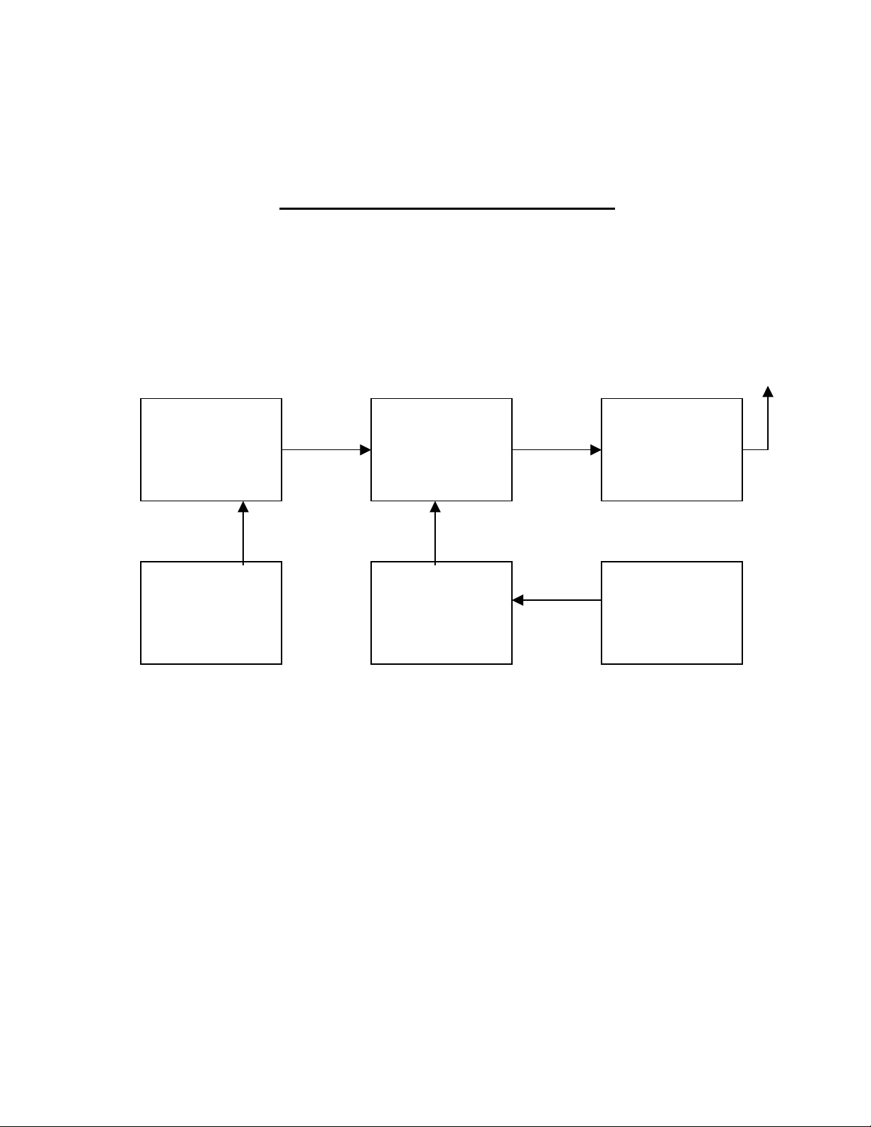
BLOCK DIAGRAM MX-3000
VIDEO PREEMPHASIS
FILTER
VIDEO INPUT
AUDIO AMPLIFIER
AUDIO INPUT
VCO / MIXER
PLL SYNTHESIZER /
REFERENCE
OSCILLATOR 4 MHz
FILTER / FINAL
AMPLIFIER STAGE
MICRO - PROCESSOR
CONTROLLER /
FREQUENCY
SETTINGS
Thank you for your purchase of the VOSTEK ELECTRONICS’ MX 3000 Video Transmitter Module. The
MX 3000 is part of a series of innovative low power Video transmitters. MX 3000 can be used for various
applications in custom Wireless Video Transmission systems, including Wireless Video Surveillance
Systems, fully duplex, remote video monitoring equipment. A practical application for these Video
Transmitters includes law enforcement and security applications. They have been employed by the military,
in research, by industry, and in a variety of recreational applications both mobile and fixed. The Instruction
Manual contains information’s MX 3000 and provides service details, alignment instruction and schematic
diagram for this transmitter.
3
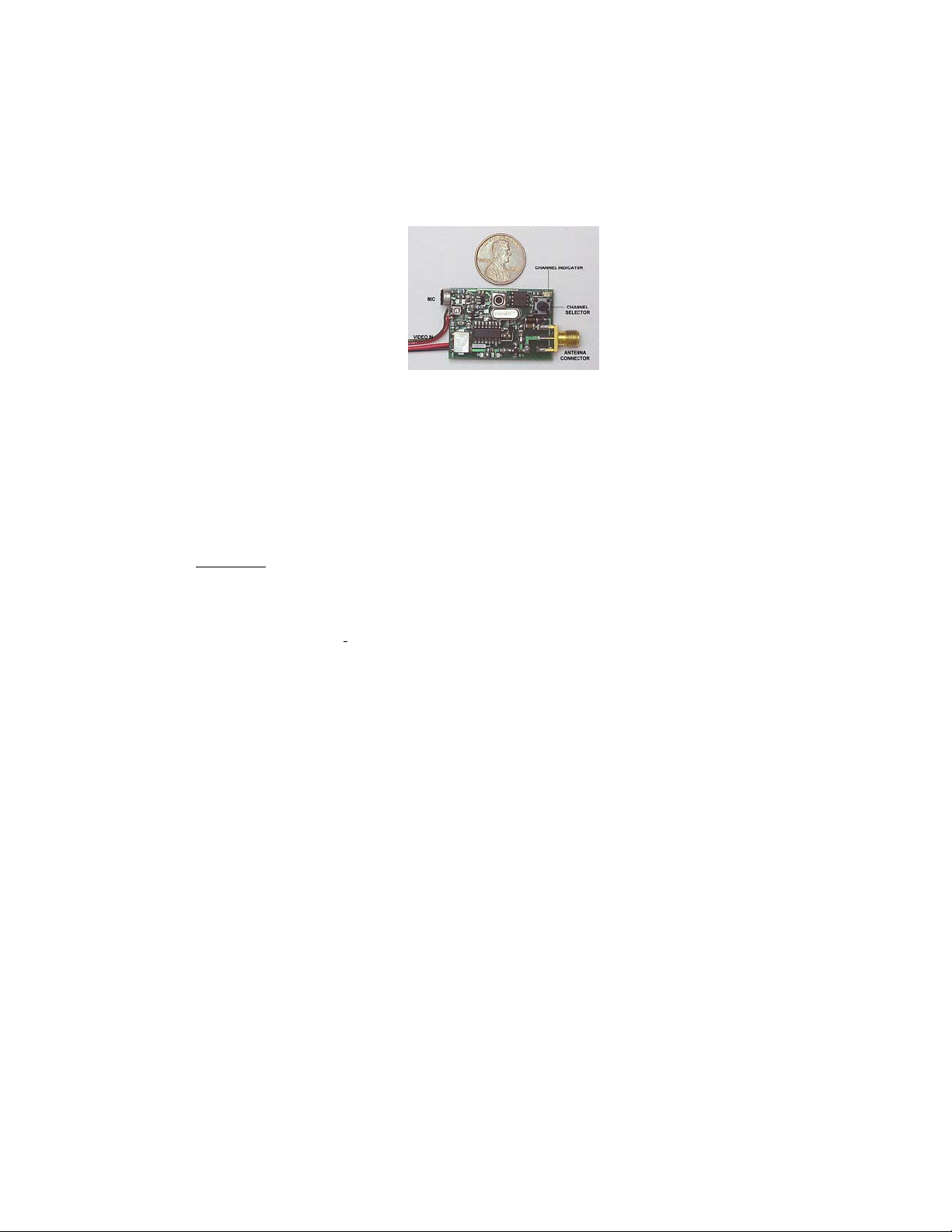
2.4 GHz AUDIO/ VIDEO TRANSMITTER MX 3000
MX 3000 is a smallest Audio/ Video transmitter for 2,4 GHz and measures only 1.5” X 1” X 0.3”. It is fully
synthesized 8 channels PLL unit, made for SECURITY applications, testing and experiments! This transmitter
has built a preemphasis filter for the best picture quality! Power supply is 9 -12 V/ 140 m A. The video level can
be adjusted with the potentiometer on the board. VRX 24 L receiver is matching unit for this transmitter. It
comes with a full 1-year warranty. The antenna connector is an SMA type. The range can be increased using
the special high gain antennas. Sound is excellent quality with a microphone built-in. Recommended receiver is
VRX 24L (PART 15 FCC rules). Recommended antenna for the transmitter is a small dipole 0 dBi or less for a
short range or directional high gain antenna up to 14 dBi. Two channels have been in use: 2452 MHz and 2481
MHz.
FEATURES:
• SIZE: 1.5” X 1” X 0.3”.
• BATTERY POWERED 9 V – 12V
• CURRENT CONSUMPTION 140mA/12V
• MODULATION WFM (
• SOUND CARRIER 6 MHz 25 kHz deviation
• MICROPROCESSOR FREQUENCY 4 MHz
• HIGH STABILITY
• TWO CHANNELS IN 2.4 GHz RANGE
• TEMPERATURE RANGE –40 +75*C
• BUILT-IN PREEMPHASIS FILTER
• VIDEO INPUT 1V PEP/75 ohm
• AUDIO INPUT 8 mV (microphone input)
• OPTIONAL EXTERNAL ANTENNA (SMA connector)
• BROADCAST QUALITY PICTURE
• REVERSE POLARITY PROTECTED
• MATCHING RECEIVER VRX 24L
• FCC PART 90 APPROVED
• 1 Y WARRANTY
0-6 MHz)
Model No: MX 3000
WARRANTY VOID IF MODIFIED!
MAX. VOLTAGE ALLOWED 12.6 V!
4

MX 3000 TECHNICAL INFORMATION:
Operating Distance
3000 ft line of sight (US / Canadian version), more or less depending on conditions, antennas
used, elevation, etc. Government & Export version will have considerably more range.
Operating Frequency
2300 MHz – 2500 MHz in 8 user selectable channels. Up to 8 systems may be used in the same
area simultaneously with VRX 24L receiver. According to FCC rules only channels 7 and 8 can
be used. Frequency 2452 MHz and 2481 MHz.
Transmission Type
FM, Crystal referenced, synthesized phase locked loop. Frequency controlled by
microprocessor. Crystal reference 4 MHz.
Frequency stability (-40 to +75º`C,
Radiated power (US & Canadian
version)
Spurious & harmonic response
Video System
Video level (internally adjustable)
Impedance
Video deviation
Antenna US/Canada:
Audio Modulation Type
Maximum deviation
System signal to noise ratio at
50kHz deviation
± 0.003%
< 50dBc
NTSC or PAL
1.0 Volt p-p into 75 Ohms
75 Ohms
± 6 MHz (adjustable from ± 1 to ± 5 MHz)
0-14 dB gain. Flexible helical type (Rubber Duck), or
PANEL (YAGI) SMA male connector
FM
± 25 kHz
65 dBA
Pre & deemphasis
Audio Input & Outputs
Microphone input level (full gain to
minimum gain)
Microphone input impedance
Power for Electret microphones
(switchable)
75µ Second
All dB figures referenced to 0 dB = 0.774Vrms
-37 dB to -6 dB for ± 50 kHz deviation (5 mV)
2k Ohms
+9 VDC @ 1mA max.
Line input impedance
10k Ohms
5

Frequency response at 20 dB below
full deviation
Total harmonic distortion (before
limiting)
40 Hz to 15 kHz +1, -3 dB, 60 Hz to 10 kHz ± 1 dB
(Option: may be extended to -3 @ 30kHz.)
0.5% at 400 Hz (0.25% typical)
Audio Carrier frequency
Audio Carrier level
Power
Transmitted power levels, current consumption and maximum voltage
Type of
Transmitter: CVT-1000
US & Canada version
Government & Export version
6.0 MHz
25 dB bellow the carrier
9 V-12 VDC Nominal. See below for details.
Transmitted
Power Levels
POWER AMP VERSION
Current Consumption /
Maximum Voltage
135 mA / 9.0V Max
Mechanical
Size
1.5" X 1" X 0.3"
Weight
With antenna 11 grams
8 grams
Connectors
Power & Audio
Video IN RCA male 75 Ohm
Antenna SMA
Environmental
Operating temperature -40ºC to +60ºC
Storage temperature -40ºC to +70ºC (-40ºF to + 158ºF)
Humidity (non-condensing) 90%
N/A
6

FREQUENCY SETTINGS AND POWER UP:
Powerup
At powerup, the unit will retrieve the last used channel, program the PLL with this channel, and display the
channel by blinking the LED the same number as the channel number 7 or 8.
Displaying Current Channel
Push button is located on the board. To display the current channel, press the pushbutton once and release.
The current channel will blink. After approx. 5 seconds, the current channel will again blink.
Changing to a New Channel
/ Frequency allocation /
Important message to users
To change to a new channel, press the pushbutton once and release. The current channel will blink. Press
and release the pushbutton again before 5 seconds has elapsed and the channel will increment by 1 and the
LED will blink the new channel. You must count to 7 in order to set the first user’s channel frequency 2452
MHz, the next channel is channel 8 (LED will blink 8 times), it means that unit is set to Channel 8
frequency 2481 MHz. Repeat this step until the desired channel is reached (channel 7 or channel 8), waiting
for the blinking to stop each time before pressing the button again.
Once your desired channel is reached (7 or 8), wait 5 seconds until the LED again blinks your desired
channel. Your new channel is now saved in memory. If unit turned off, the microprocessor will save in
memory the last used channel.
Channels 7 and 8 have been in use
FREQUENCIES: 2452 MHz and 2481 MHz
NOTE: DO NOT USE ANY OTHER CHANNELS (FREQUENCIES) OUTSIDE OF FCC LIMITS.
USE STRICTLY CHANNELS 7 or 8. THE OTHER CHANNELS (FREQUENCIES) OUTSIDE OF THE
AUTHORIZED BAND ARE PROHIBITED AND NOT RECOMMENDED BY THE MANUFACTURER!
ALL WARRANTIES VOID IF MODIFIED!
7

INSTRUCTIONS:
1. CONNECT THE ANTENNA TO SMA CONNECTOR
2. CONNECT DC BATTERY POWER 9 V – 12 V
3. SWITCH TO THE CHANNEL 7 or 8 BY FOLLOWING THE INSTRUCTION ABOVE
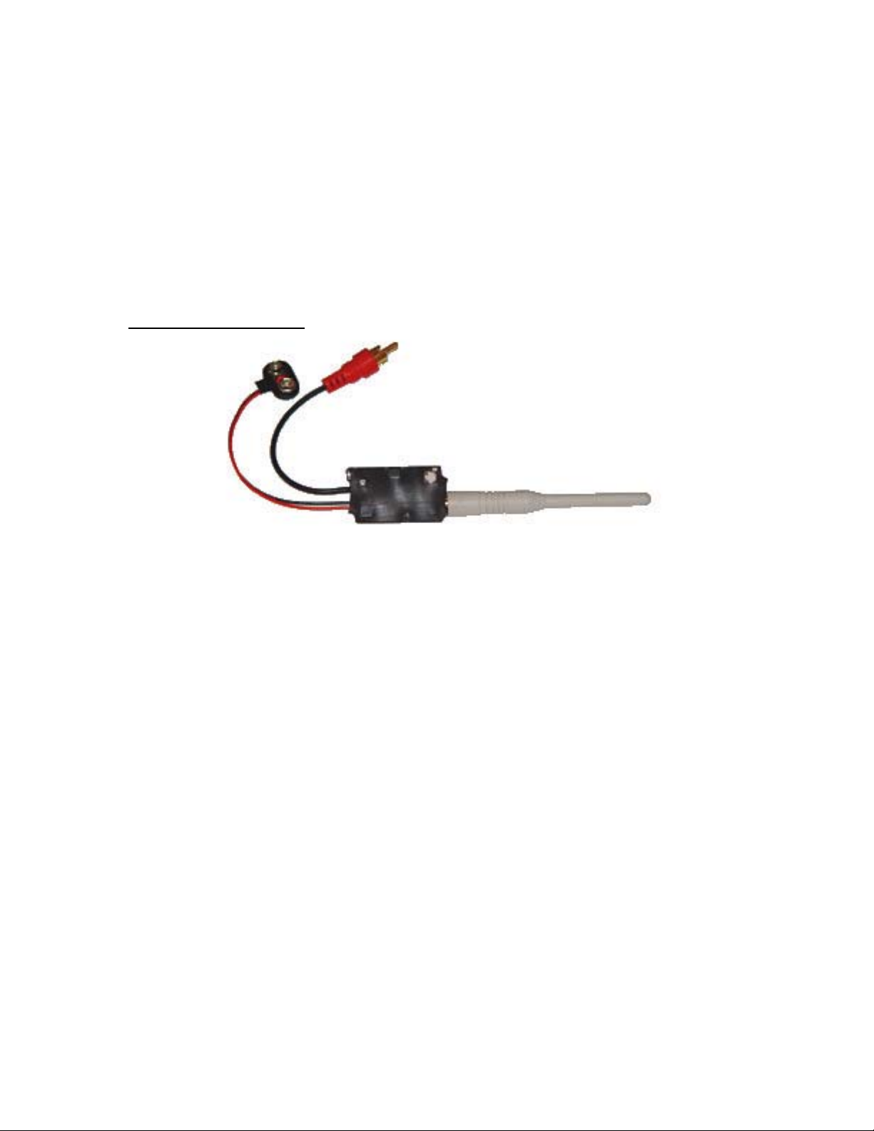
4. CONNECT RCA CABLE TO VIDEO SOURCE 1 V / 75 OHMS
5. SWITCH ON RECEIVER VRX 24L FOR DESIRED CHANNEL 7 OR 8
6. CONNECT THE RECEIVER TO VIDEO (AUDIO) MONITOR
1.
Warning to Users @ FCC 15.21 & 15.105
Warning: Changes or modifications not expressly approved by Vostek electronics
could void the user’s authority to operate the equipment
8

2.
FCC Label @ FCC 15.19
For Class B - Unintentional Radiators
•
This device complies with Part 15 of the FCC Rules. Operation is subject to the following two
conditions: (1) this device may not cause harmful interference and (2) this device must accept any
interference received, including interference that may cause undesired operation.
FCC ID: OGR-MX 3000
RF EXPOSURE REQUIREMENTS @ 1.1310 & 2.1091
FCC INFO:
This equipment has been tested and found to comply with the limits for Class B digital devices, pursuant to
Part 15 of the FCC Rules. These limits are designed to provide reasonable protection against harmful
interference in a residential installation. This equipment generates, uses, and can radiate radio frequency
energy and, if not installed and used in accordance with the instruction manual, may cause harmful
interference to radio communications. However, there is no guarantee that interference will not occur
in a particular installation. If this equipment does cause harmful interference to radio or television
reception, which can be determined by turning the equipment off and on, the user is encouraged to try to
correct the interference by one of more of the following measures:
• Reorient or relocate the receiving antenna
• Increase the separation between the equipment and receiver
• Connect the equipment into an outlet on a circuit different from that to which the receiver is
connected.
• Consult the dealer or an experienced radio/TV technician for help.
FCC ID: OGR-MX3000
MODEL: MX 3000
VOSTEK ELECTRONICS
FCC LABEL
9

TOP AND BACK OF THE UNIT
CONTACT INFO:
VOSTEK ELECTRONICS
P.O. BOX 60043, 1032 PAPE AVETORONTO, ONT
M4K 3Z3
Email: vostek@globility.com
10

NOTE:
ATTENTION TO OEM USERS OF OUR WIRELESS VIDEO/AUDIO MODULE MX-3000:
The OEM Manufacturer who employs our wireless module MX-3000 must have their own
FCC ID Label with the following wording:
"This device contains Vostek Electronics’ Radio Module” FCC ID: OGR-MX3000
FCC LABEL:
11
 Loading...