

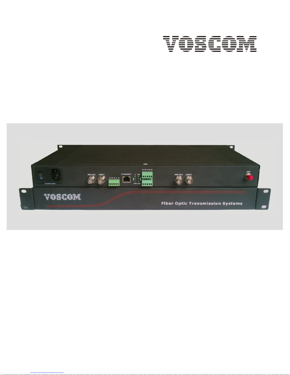
VOS-2HD-ADCET/R series
2-Channel HD-SDI + 2 Duplex Audio + 1 Duplex Data
+ 2 Simplex (or 1 Duplex) Contact Closure
+ IP Ethernet
Installation Manual
Fiber Optic Transmission Systems
VOSCOM TECHNOLOGIES CO.,LIMITED
WWW.VOSCOM.COM
TM
19inch 1U Rack version
Important Safety Instructions
EN_1
1. Read these instructions. Keep these instructions. Heed all warnings. Follow all instructions.
5. Do not use this apparatus near water. Clean only with dry cloth.
7. Do not block any ventilation openings. Install in accordance with the manufacturers
instructions.
8. Do not install near any heat sources such as radiators, heat registers, stoves, or other
apparatus (including amplifiers) that produce heat.
9. Do not defeat the safety purpose of the polarized or grounding-type plug. A polarized plug
has two blades with one wider than the other. A grounding type plug has two blades and a third
grounding prong. The wide blade or the third prong are provided for your safety. If the provided
plug does not fit into your outlet consult an electrician for replacement of the obsolete outlet.
10. Protect the power cord from being walked on or pinched particularly at plugs, convenience
receptacles, and the points where they exit from the apparatus.
13. Refer all servicing to qualified service personnel. Servicing is required when the apparatus
has been damaged in any way, such as power-supply cord or plug is damaged, liquid has been
spilled or objects have fallen into the apparatus, the apparatus has been exposed to rain or
moisture, does not operate normally, or has been dropped.
14. Apparatus shall not be exposed to dripping or splashing and that no objects filled with liquids,
such as vases shall be placed on the apparatus.
15. WARNING: To reduce the risk of fire or electric shock, do not expose this apparatus to rain or
moisture.
16. Installation should be done only by qualified personnel and conform to all local codes.
20. CAUTION: These servicing instructions are for use by qualified service personnel only. To
reduce the risk of electric shock do not perform any servicing other than that contained in the
operating instructions unless you are qualified to do so.
Website:www.voscom.comWebsite:www.voscom.com
Product Overview
En_2
22
HD-SDI
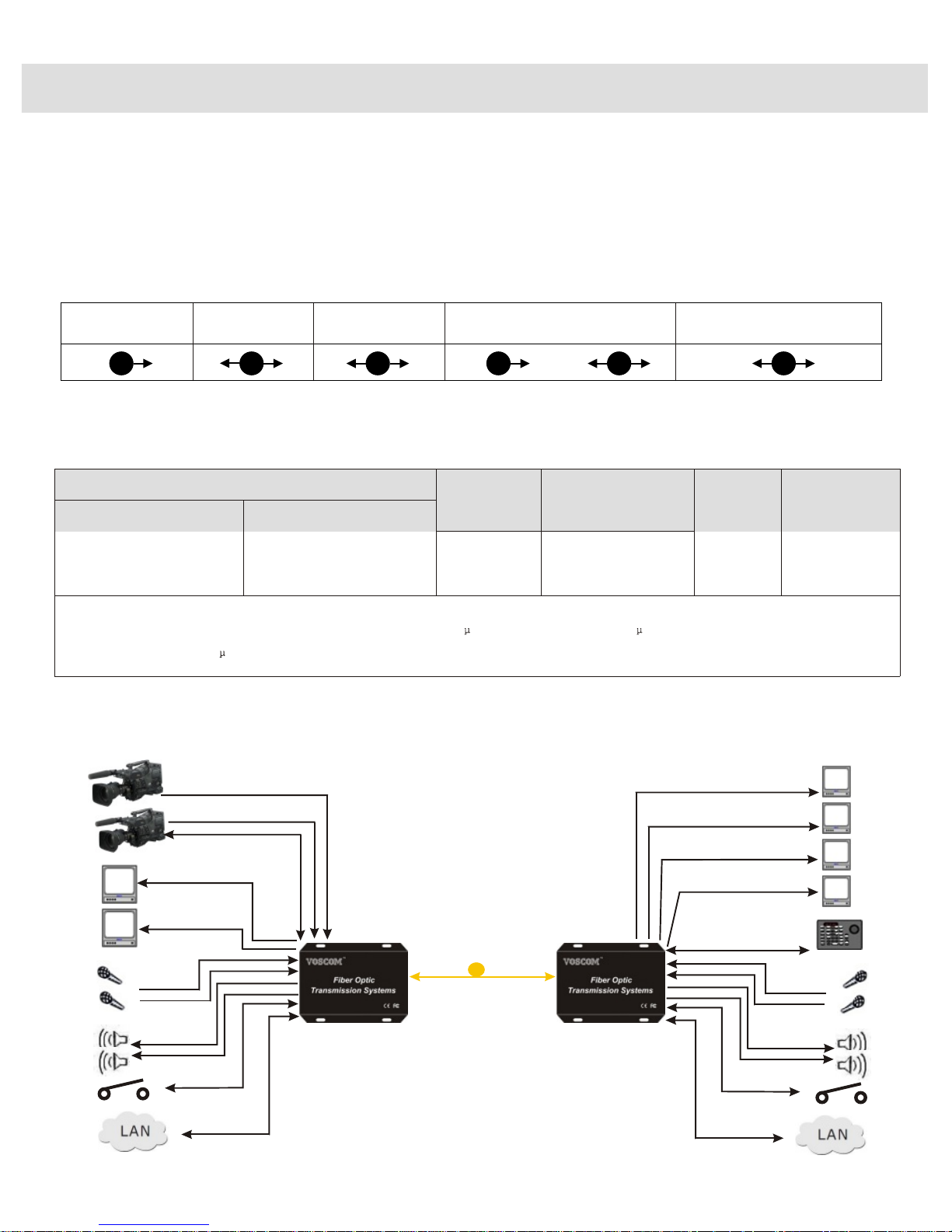
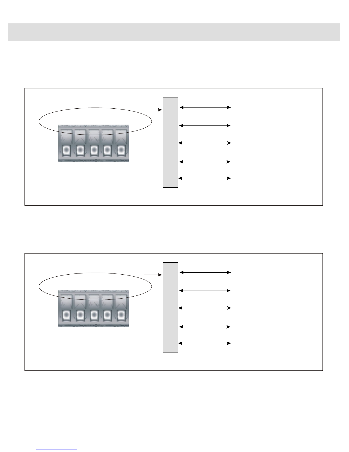
The VOS-2HD-ADCET/R provides for the digital transmission of 2-Channel uncompressed
1.485Gbps HD-SDI (SMPTE 292) or 270 Mbps SD-SDI (SMPTE 259M) 1080P HD video over fiber,
support 2 duplex analog audio, 1 duplex RS232 /RS485 data, 2 simplex or 1 duplex contact closure,
and 1-channel 10M/100M IP Ethernet, also support one loopback output for local display, and dual
outputs for two displays in the remote end.
Model Number
Transmitter Receiver
Fiber Mode Wavelengths
Optical
Power
Budget
Maximum
Transmission
Distance
Multi-Mode 1310nm/1550nmVOS-2HD-ADCEMRVOS-2HD-ADCEMT
•The Optical Power Budget data fit Mulit-mode(62.5/125 m),Single-Mode(9/125 m).
•When using 50/125 m multimode fiber, subtract 3 dB from the optical power budget.
Note:
16dB
300m
Single-Mode
VOS-2HD-ADCESRVOS-2HD-ADCEST 12dB 20km
Models and Optical Power Budget:
Audio
1310nm/1550nm
Data
1122
System Diagram:
Ethernet
11
Contact Closure
22
or
11
1 Fiber optic Cable
VOS-2HD-ADCET
Transmitter
VOS-2HD-ADCER
Receiver
Loop output
1 x Duplex Data
HD-SDI Source
with PTZ Mount
HD-SDI Input
HD-SDI Output
HD-SDI Output
PTZ Controller
1 x Duplex Data
IP Ethernet
2 Duplex Audio
Contact Closure
IP Ethernet
2 Duplex Audio
Contact Closure
Display
Display

Panel & Cable Connection
En_3
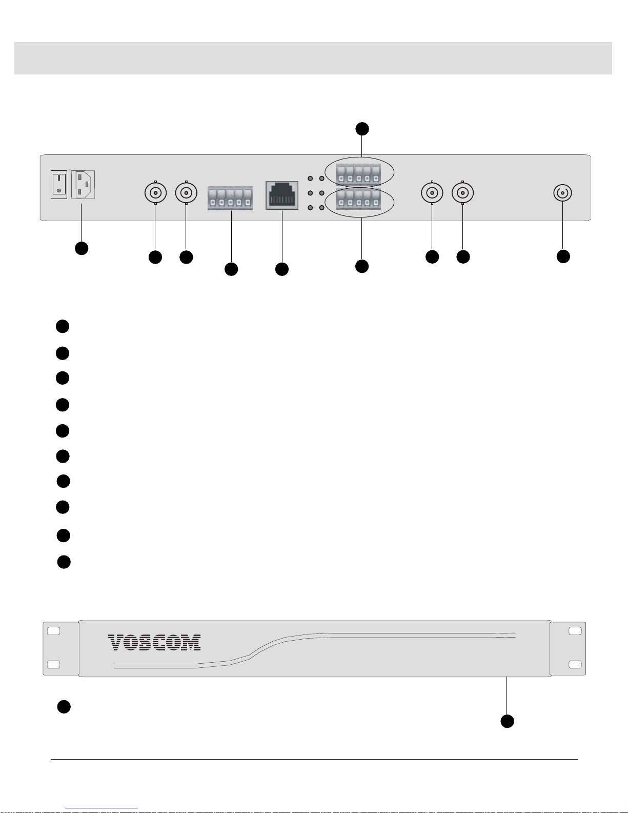
Transmitter Panel:
1
3
4
5
SDI-IN2 Connector: The Second Channel HD-SDI/SD-SDI video input.
LOUT2 Connector: The Second Channel HD-SDI video Loopback output for loacal display.
5-PIN Terminal Block Data Connector: 1-Channel Duplex Rs232/R485 Data Input/Output.
6
Ethernet Connector: Standard RJ-45 10M/100M Ethernet, Automatic support MDI/MDI-X.
7
5-PIN Terminal Block Audio Connector: 2-Channel Duplex Analog Audio Input/Output.
9
Fiber Optic Connector: support FC/PC or ST/PC optical connector.
1
Website:www.voscom.comWebsite:www.voscom.com
8
5-PIN Terminal Block CC Connector: 2 Simplex or 1 duplex Contact Closure Input/Output.
ON
OFF
AC100V~240V
OPT
SDI-IN1
LOUT1
POW
SYS
V
TXD
LOCK
RXD
A B G C D
ETHERNET
A1 B1 G A 2 B2
A3 B3 G A 4 B4
SDI-IN2
LOUT2
2
3 4
1
1
2
SDI-IN1 Connector: The First Channel HD-SDI/SD-SDI video input.
LOUT1 Connector: The First Channel HD-SDI video Loopback output for loacal display.
5 6
7
8
9
10
10
Power supply Connector: AC100V~240V Input
TRANSMITTER FRONT PANEL
Fiber Optic Transmission Systems
TRANSMITTER REAR PANEL
11
11
19inch, 1U Rack-mount Transmitter.
Panel & Cable Connection
En_4
Receiver Panel:
1
3
4
5
SDI-OUT3 Connector: The Second Channel HD-SDI/SD-SDI video Output 1.
SDI-OUT4 Connector: The Second Channel HD-SDI/SD-SDI video Output 2.
5-PIN Terminal Block Data Connector: 1-Channel Duplex Rs232/R485 Data Input/Output.
6
Ethernet Connector: Standard RJ-45 10M/100M Ethernet, Automatic support MDI/MDI-X.
7
5-PIN Terminal Block Audio Connector: 2-Channel Duplex Analog Audio Input/Output.
9
Fiber Optic Connector: support FC/PC or ST/PC optical connector.
1
Website:www.voscom.comWebsite:www.voscom.com
8
5-PIN Terminal Block CC Connector: 2 Simplex or 1 duplex Contact Closure Input/Output.
ON
OFF
AC100V~240V
OPT
SDI-OUT1
SDI-OUT2
POW
SYS
V
TXD
LOCK
RXD
A B G C D
ETHERNET
A1 B1 G A 2 B2
A3 B3 G A 4 B4
SDI-OUT3
SDI-OUT4
2
3 4
1
1
2
SDI-OUT1 Connector: The First Channel HD-SDI/SD-SDI video Output 1.
SDI-OUT2 Connector: The First Channel HD-SDI/SD-SDI video Output 2.
5 6
7
8
9
10
10
Power supply Connector: AC100V~240V Input
RECEIVER FRONT PANEL
Fiber Optic Transmission Systems
RECEIVER REAR PANEL
11
11
19inch, 1U Rack-mount Receiver
Panel & Cable Connection
En_5
5 Pin Terminal Block
A
B
G
C
D
Conect Ground (GND)
PIN
Conect Data Rs485+(A)
Conect Data Rs232 RXD
Receiver (Data): 1-Channel Duplex Rs232/Rs485 Data (Input/Output)
Transmitter (Data): 1-Channel Duplex Rs232/Rs485 Data (Input/Output)
Data Connection:
Input/Output
Input/Output
Input/Output
A B G C D
Conect Data Rs485-(B)
Input/Output
Conect Data Rs232 TXD
Input/Output
5 Pin Terminal Block
A
B
G
C
D
Conect Ground (GND)
PIN
Conect Data Rs485+(A)
Conect Data Rs232 RXD
Input/Output
Input/Output
Input/Output
A B G C D
Conect Data Rs485-(B)
Input/Output
Conect Data Rs232 TXD
Input/Output
Website:www.voscom.comWebsite:www.voscom.com

Panel & Cable Connection
En_6
5-Pin Terminal Block
PIN
Transmitter (Audio): 2-Channel Duplex Audio (Input/Output)
Audio Connection:
A3 B3 G A4 B4
A3
B3
G
A4
B4
1st-Channel Audio Input
Conect all GND to this PIN
Input/Output
2nd-Channel Audio Input
Receiver (Audio): 2-Channel Duplex Audio (Input/Output)
Website:www.voscom.comWebsite:www.voscom.com
Input
1st-Channel Audio Output
2nd-Channel Audio Output
Input
Output
Output
5-Pin Terminal Block
PIN
A3 B3 G A4 B4
A3
B3
G
A4
B4
1st-Channel Audio Input
Conect all GND to this PIN
Input/Output
2nd-Channel Audio Input
Input
1st-Channel Audio Output
2nd-Channel Audio Output
Input
Output
Output

Panel & Cable Connection
En_7
5-Pin Terminal Block
PIN
Transmitter (Contact Closure): 2-Channel Simplex CC Input
2-Channel Simplex Contact Closure Connection:
A1 B1 G A2 B2
A1
B1
G
A2
B2
2-Channel CC Input
None
2-Channel CC Input
Receiver (Contact Closure): 2-Channel Simplex CC Output
Input
1-Channel CC Input
1-Channel CC Input
Input
Input
Input
NOTE: the device can support 2 simplex or 1 duplex contact closure,
but it only can be configurated by factory, so you need to choose the
configuration before the order.
5-Pin Terminal Block
PIN
A1 B1 G A2 B2
A1
B1
G
A2
B2
2-Channel CC Output
None
2-Channel CC Output
Output
1-Channel CC Output
1-Channel CC Output
Output
Output
Output

Panel & Cable Connection
En_8
5-Pin Terminal Block
PIN
Transmitter (Contact Closure): 1-Ch Duplex CC Input/Output
1-Channel Duplex Contact Closure Connection:
A1 B1 G A2 B2
A1
B1
G
A2
B2
1-Channel CC Input
None
1-Channel CC Input
Receiver (Contact Closure): 1-Ch Duplex CC Input/Output
Input
1-Channel CC Output
1-Channel CC Output
Input
Output
Output
NOTE: the device can support 2 simplex or 1 duplex contact closure,
but it only can be configurated by factory, so you need to choose the
configuration before the order.
5-Pin Terminal Block
PIN
A1 B1 G A2 B2
A1
B1
G
A2
B2
1-Channel CC Input
None
1-Channel CC Input
Input
1-Channel CC Output
1-Channel CC Output
Input
Output
Output

Panel & Cable Connection
En_9
HD-SDI TRANSMMITTER
HD-SDI RECEIVER
A1 B1 G A 2 B2
ON
SDI-IN1
LOUT1
V
TXD
ETHERNET
SDI-IN2
LOUT2
OPT
A B G C D
SYS
RXD
OFF
AC100V~240V
POW
LOCK
A3 B3 G A 4 B4
A1 B1 G A 2 B2
ON
SDI-OUT1
SDI-OUT2
V
TXD
ETHERNET
SDI-OUT3
SDI-OUT4
OPT
A B G C D
SYS
RXD
OFF
AC100V~240V
POW
LOCK
A3 B3 G A 4 B4
Power Supply
Power Supply
Display
Display
H
D-
S
DI
Inp
ut
HD
-SD
I I
np
ut
L
o
c
a
l L
o
o
p
b
a
ck
L
oc
al
L
oopb
a
ck
1-Channel Duplex RS-232/RS-485 Data
HD-SDI Source
with PTZ Mount
HD-SDI Source
with PTZ Mount
2-
C
h
anne
l
D
u
plex Aud
i
o
Display Display Display Display
Control Device
2-
C
h
anne
l
D
u
plex Aud
i
o
I
P
Et
her
ne
t
I
P
E
t
her
ne
t
Contact Closure
Contact Closure
HD-SDI Output HD-SDI Output
HD-SDI Output HD-SDI Output
D
upl
e
x
R
S
-
2
32/R
S-4
85
D
a
ta

Stand-alone Installation
En_10
The transmitter/ receiver can be mounted into a rack or can
be used as a stand-alone module. As a stand-alone module, the unit can be placed on a desktop
or can be mounted to a wall. This manual is for the 19inch 1U rack.
VOS-2HD-ADCET VOS-2HD-ADCER
NOTE: Before mounting the transmitter/ receiver, please
ensure that there is adequate space at both ends for viewing the front-panel LEDs and for
making the various rear-panel cable connections.
VOS-2HD-ADCET VOS-2HD-ADCER
Standard 19inch 1U Rack: 483mm x 250mm x 44.5mm
Website:www.voscom.comWebsite:www.voscom.com

Troubleshooting
En_11
Indicator Status Meaning Possible Cause Corrective Action
Power LED
Light
Power is being applied
to the module.
---
No action required.
Not Light Power is not being
applied to the module.
Check power connection.
If module is rack mounted,
reseat module or power
supply as necessary.
Power connection is
faulty.
Power supply has failed.
Replace power supply.
Loss of power occurs due
to tripped circuit
breaker(s), blown fuse(s),
or faulty electrical
service.
Check circuit breaker(s),
fuse(s), or electrical
service as necessary.
LED indicators on the front-panel of the transmitter/receiver allow you to monitor signal status,
laser status, data activity, contact closure activation, and operating power. Table A~D provide
information about the front-panel indicators and associated troubleshooting guidelines.
Table A: Power Links
Indicator Status Meaning Possible Cause Corrective Action
Video LED(VIDEO 1,VIDEO 2....)
Light
Incoming video signal
is present on thechannel.
---
No action required.
Not Light
on Transmitter
Incoming video signal
is not present on the
channel.
Check power connection
to the video source.
Video source is not
powered on.
Video source is not
connected to the
transmitter.
Check BNC connections.
Coaxial cable is
defective.
Replace cable.
Table B: Video Links
Not Light
on Receiver
Incoming video signal
is not present on the
channel.
Optical signal is not
being received from the
transmitter. Optic Fault
LED is also not light.
Refer to the Optic Fault
LED section in this table.
Video source is not
powered on.
Check power connection
to the video source.
Video source is not
connected to the
transmitter.
Check BNC connections.
Coaxial cable connected
to the transmitter is
defective.
Replace cable.
Website:www.voscom.com

Troubleshooting
En_12
Indicator Status Meaning Possible Cause Corrective Action
Data(RS485/RS232/RS422) LED
Flashing
Data is being transmitted
onto the fiber by the data
port or is being received
from the fiber by the
data port.
---
No action required.
Table C: Data Links
Indicator Status Meaning Possible Cause Corrective Action
Optic LED
Light
The optical signal is being
received and laser is
operatingproperly.
---
No action required.
Not Light
Table B: Optic Links
Not Light
Data is not being
transmitted onto the
fiber by the data port or
is not being received
from the fiber by the
data port.
Data is not present on
the channel.
No action required.
Data connection is faulty.
Check data connections.
Data communication
cable is defective.
Replace cable.
The optical signal is
not being received.
Remote fiber module is
not powered on.
Check power connections.
Replace power supply if
necessary.
Fiber optic cable is not
connected.
Check fiber optic
connections.
Fiber optic cable
connectors are dirty or
are damaged.
Clean, polish, or replace
fiber optic cable
connectors as necessary.
Fiber optic cable is
defective.
Replace cable.
A problem exists with
the optical power
budget.
Verify that losses in fiber
optic cable do not exceed
the optical power budget
specification of the fiber
optic link. If the losses do
exceed the optical power
budget, contact Product
Support.
Website:www.voscom.com

Return & Warranty Policy
En_13
Warranty Introduction
All VOSCOM manufactured products are warranted to be free from defects in manufacturing and
materials for the warranty term of 3 years. VOSCOM will repair or replace any equipment or parts
proved to be defective during the term of the warranty.
VOSCOM shall not be obligated to replace or repair equipment that has been damaged by fire,
war, acts of God, or similar causes, or equipment that has been serviced by unauthorized
personnel, altered, improperly installed or abused.
This Return and Warranty Policy Statement applies to VOSCOM equipment purchased directly
from VOSCOM Technologies Co.,Ltd. If you did not acquire the VOSCOM equipment directly, return
the equipment to the place of purchase.
Returning VOSCOM products
Before you can return any product to VOSCOM, you must obtain a Return Material Authorization
(RMA). This applies to all product returns, including warranty repair/replacements, nonwarranty
repairs, advance replacements, and credit returns.
To obtain an RMA, (Download from www.voscom.com), and please complete the RMA as much
detail as possible, then send the RMA to our customer service support:
FAX: +86-571-87389390
E-mail: RMA@voscom.com
Customer Service will provide you with an RMA number and an RMA acknowledgment form that
confirms your request.
Once you have the RMA, repackage the product appropriately and attach the RMA
acknowledgement form on the outside of the package. Then send the product to the return
location given by the customer service center.
All products must be returned freight prepaid within 30 days of obtaining an RMA. We reserve
the right to cancel the RMA after 30 days. If you fail to return the product within the 30 days,
please contact Customer Service to get a new RMA.
We will not accept unauthorized returns or freight collection returns; we will return these to
you at your expense.
If a returned product contains parts that are no longer available or repairable, we will contact
you to discuss resolution and return of the material.
Website:www.voscom.comWebsite:www.voscom.com

En_14
Warranty repair/replacements
Subject to the terms of the limited warranty in effect at the time of purchase, VOSCOM will
repair or replace a product that fails to meet the terms provided, within the product's warranty
period. The actual warranty period starts from either:
a): The date of shipment from VOSCOM's facility (point of origin)
b): The manufacturer's date code (if the shipment date is unknown).
For all warranty repairs, VOSCOM will cover parts and labor. We will return equipment via the
same incoming shipment method at no additional charge.
Non-warranty repairs
For all non-warranty repairs, VOSCOM will provide you with a repair estimate that includes
charges for parts, labor (in half-hour increments), and all shipping. Repair charges may be
based on a flat rate or parts and labor, and will vary based on actual equipment and condition.
You may pay for non-warranty repair charges by purchase order.
Advance replacement
Advance replacement products are new or like-new refurbished products and carry a full original
equipment warranty. VOSCOM will send advance replacement product to replace defective
equipment that has failed upon initial install for up to 60 days from the original date of shipment.
We will ship advance replacements in the next business day.
Our repair department will evaluate the returned product to determine whether it is a warranty
or non-warranty replacement and bill you accordingly. We will invoice advance replacements at
shipment and credit you upon receipt of the defective product. If we determine, however, that the
returned product is in good working order or that performance issues were due to improper
installation, misuse, abuse, or other user-related causes, we will issue no credit and you will
remain responsible for paying the invoice.
Note: Advance replacement is not available for custom products.
Credit returns
VOSCOM will refund or credit new, standard production items that are unused and in the original
unopened shipping cartons for a period of 60 days from the original date of shipment. All returned
merchandise is subject to a 20% restocking fee. Products that have failed upon initial install within
60 days from the date of shipment (or date of manufacture if shipment date is unknown) may be
returned for credit without a restocking fee. (Products purchased as part of a kit must be returned
through Advance replacement.)
As with advance replacements, if we determine that the returned product is in good working
order or that performance issues were due to improper installation, misuse, abuse, or other
user-related causes, we will issue no credit and you will remain responsible for paying the invoice.
Note: Credit is not available for custom products.
Return & Warranty Policy
Website:www.voscom.comWebsite:www.voscom.com

Packing List & Support
En_15
Manufacture Packing List:
Fiber Optic Transmitter 1
Fiber Optic Receiver 1
Power Adapter 2
User Manmual 1
Note:
1): VOSCOM reserves the right to change specifications without notice.
2): You can download the latest PDF document here: www.voscom.com
3): Online Technical Support please E-mail:support@voscom.com
4): More detail product information please E-mail: sales@voscom.com, or contact
with our sales staff.
5): Return defective products please download RMA here: www.voscom.com
6): Get an
acknowledgment RMA number please complete the RMA as much detail as possible
and then E-mail: RMA@voscom.com or FAX:+86-571-87389390
Website:www.voscom.comWebsite:www.voscom.com

WARNING
TO REDUCE THE RISK OF FIRE OR SHOCK HAZARD, DO
NOT EXPOSE THIS PRODUCT TO RAIN OR MOISTURE.
DO NOT LOOK INTO OPTICAL PORTS WITH POWER ON.
Headquarters Information:
Distributor Information:
VOSCOM TECHNOLOGIES CO., LIMITED
Hangzhou , Zhejiang , P.R.CHINA 310004
Tel:+86-571-87389389
Fax:+86-571-87389390
Web:www.voscom.com
E-Mail:sales@voscom.com
support@voscom.com
RMA@voscom.com
 Loading...