

Voscom VOS-1DVI-LTR seriesw, VOS-1VGA-LT series, VOS-1VGA-LR series, VOS-1DVI-LT Series, VOS-1DVI-LR Series Installation Manual
VOS-1DVI-LT/R series
1-Channel DVI Extender over Fiber
Installation Manual
Fiber Optic Transmission Systems
VOSCOM TECHNOLOGIES CO.,LIMITED
WWW.VOSCOM.COM
TM
Important Safety Instructions
EN_1
1. Read these instructions. Keep these instructions. Heed all warnings. Follow all instructions.
5. Do not use this apparatus near water. Clean only with dry cloth.
7. Do not block any ventilation openings. Install in accordance with the manufacturers
instructions.
8. Do not install near any heat sources such as radiators, heat registers, stoves, or other
apparatus (including amplifiers) that produce heat.
9. Do not defeat the safety purpose of the polarized or grounding-type plug. A polarized plug
has two blades with one wider than the other. A grounding type plug has two blades and a third
grounding prong. The wide blade or the third prong are provided for your safety. If the provided
plug does not fit into your outlet consult an electrician for replacement of the obsolete outlet.
10. Protect the power cord from being walked on or pinched particularly at plugs, convenience
receptacles, and the points where they exit from the apparatus.
13. Refer all servicing to qualified service personnel. Servicing is required when the apparatus
has been damaged in any way, such as power-supply cord or plug is damaged, liquid has been
spilled or objects have fallen into the apparatus, the apparatus has been exposed to rain or
moisture, does not operate normally, or has been dropped.
14. Apparatus shall not be exposed to dripping or splashing and that no objects filled with liquids,
such as vases shall be placed on the apparatus.
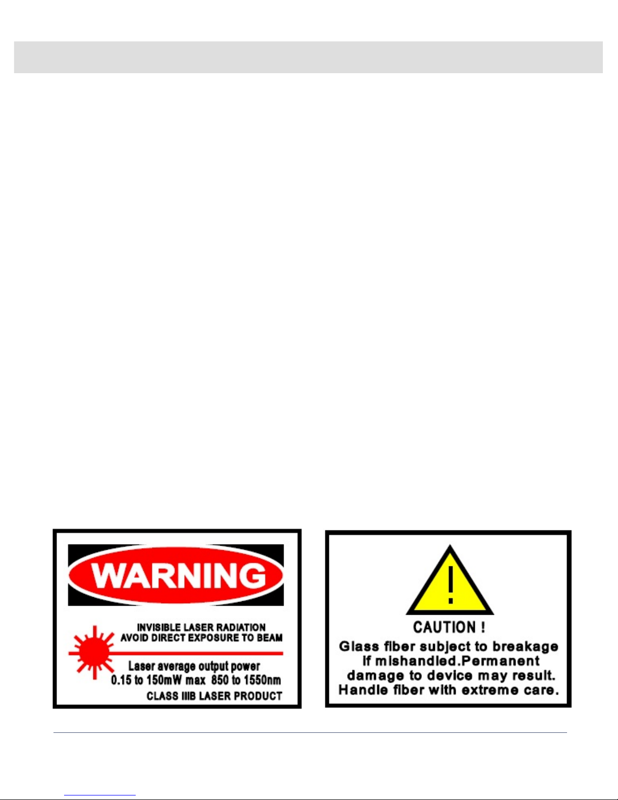
15. WARNING: To reduce the risk of fire or electric shock, do not expose this apparatus to rain or
moisture.
16. Installation should be done only by qualified personnel and conform to all local codes.
20. CAUTION: These servicing instructions are for use by qualified service personnel only. To
reduce the risk of electric shock do not perform any servicing other than that contained in the
operating instructions unless you are qualified to do so.
Website:www.voscom.com
Product Overview
En_2
11
DVI
The VOS-1DVI-LT/R provides for the digital
transmission of 1-Channel uncompressed DVI video
resolutions up to WUXGA 1920x1200 and HDTV Video
resolutions up to 1080p. support singlemode or
multimode fiber cable. Support one DVI loopback output for local display.
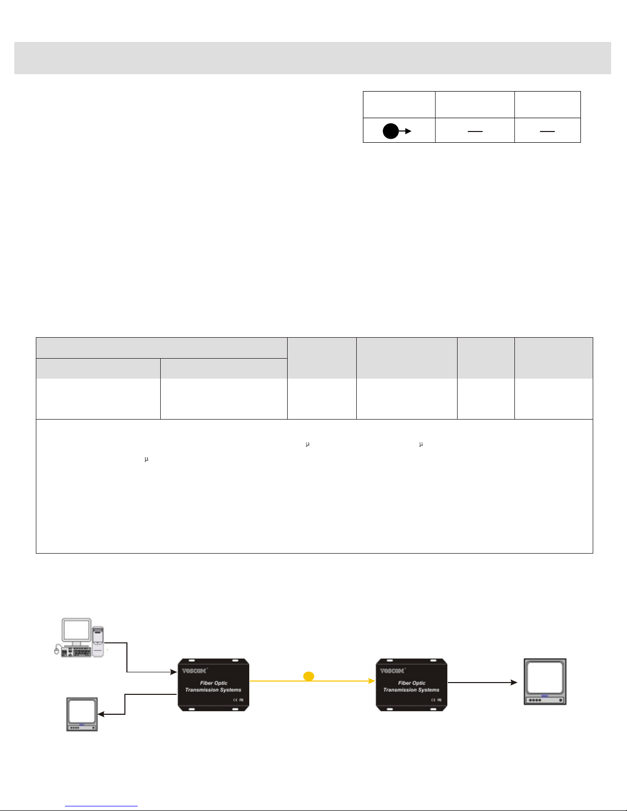
System Diagram:
Model Number
Transmitter Receiver
Fiber Mode Wavelengths
Optical
Power
Budget
Maximum
Transmission
Distance
Multi-Mode 1310nm/1550nm
•The Optical Power Budget data fit Mulit-mode(62.5/125 m),Single-Mode(9/125 m).
•When using 50/125 m multimode fiber, subtract 3 dB from the optical power budget.
•Optical transmission distance is limited to optical loss of the fiber and any additional loss introduced by connectors,
splices and patch panels.
•Maximum transmission distance is also limited by fiber bandwidth.
•Power adapter is manufactured by third party and is supplied with fitted screw-terminal output cables.Power
adapter included (for standalone) US, European, UK or Australian power plug.
•Please feel free to consult factory for any special requirement and customization
Note:
16dB
300m
Single-Mode
VOS-1DVI-LRVOS-1DVI-LT
12dB 15km
Models and Optical Power Budget:
Extends uncompressed DVI over one fiber
•Supports DVI resolutions up to WUXGA 1920x1200
•Supports HDTV resolutions up to 1080p
•Multimode Fiber Support for Distances up to 300m
•Single-Mode Fiber Support for Distances up to 15 km
•Stand alone or rack-mount
•
Features:
Audio
1310nm/1550nm
Data
1 Fiber optic Cable
Monitor
VOS-1DVI-LT
Transmitter
VOS-1DVI-LR
Receiver
Loopback out
DVI output
Computer
Monitor
DVI input
Panel & Cable Connection
En_3
OPT
PWR
RST
SYS
V
4
ON
DATA
SW
32
DIP
1
A-IN
A-OUT
TRANSMITTER FRONT PANEL
TRANSMITTER REAR PANEL
DVI-OUTDVI-IN
DC5V
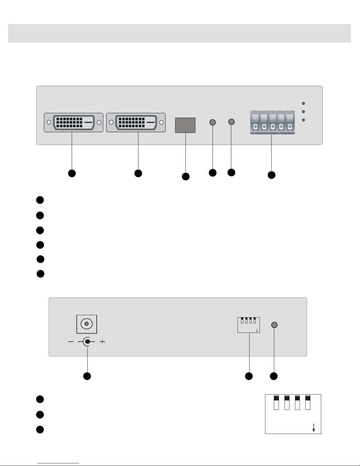
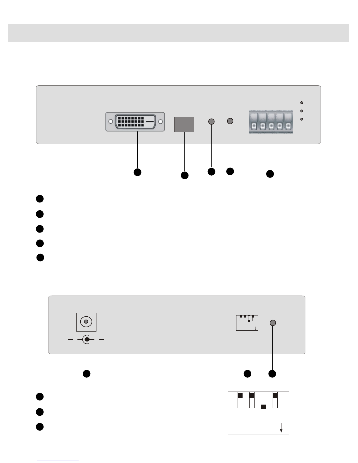
Transmitter Panel:
1 2
3
4
5
6
1
1
2
3
DVI-D DVI Connector: DVI Input
DVI-D DVI Connector: DVI Output, DVI Loopback Output for local display.
No function, No Audio support for this model.
4
No function, No Audio support for this model.
5
No function, No Rs232/485 data support for this model.
6
Fiber Optic Connector: support LC Connector (Single-Core)
1
7
8
9
Stand-alone Power supply Connector: DC5V 2A Input
Switcher, Do not need to set up, Keep the default, all switchers UP
Reset Botton: reset the status of the device
7 8 9
1 2 3 4 5
4
ON
32
DIP
1
None
None None
Panel & Cable Connection
En_4
RST
4
ON
SW
32
DIP
1
DC5V
Receiver Panel:
1
1
2
3
DVI-D DVI Connector: DVI output.
No function, No Audio support for this model.
No function, No Audio support for this model.
4
No function, No Rs232/485 data support for this model.
5
Fiber Optic Connector: support LC Connector (Single-Core)
1
7
8
9
Stand-alone Power supply Connector: DC5V 2A Input
Switcher, Keep the default, 1, 2 & 4 UP, 3-PIN DOWN
Reset Botton: reset the status of the device
7 8 9
OPT
PWR
SYS
V
DATA
A-IN
A-OUT
1
2
3
4
5
1 2 3 4 5
RECEIVER FRONT PANEL
RECEIVER REAR PANEL
4
ON
32
DIP
1
DVI-OUT
None
None None
 Loading...