

Page 1
Libretto d’istruzioni
Instruction booklet
Notice de pose et d’entretien
Betriebsanleitung
Folleto de instrucciones
Manual de instruçoes
Gebruiksaanwijzing
Instruktionshäfte
VORT MAX S
VORTICE LIMITED
Milley Lane - Hare Hatch
Reading - Berkshire - RG10 9TH
Tel.(+ 44) 118 -94.04.211
Fax (+44) 118-94.03.787
UNITED KINGDOM
VORTICE ELETTROSOCIALI S.p.A.
Strada Cerca, 2 - frazione di Zoate
20067 TRIBIANO (MI)
Tel.(+ 39) 02-90.69.91
Fax (+39) 02-90.64.625
ITALIA
VORTICE FRANCE
72 Rue Baratte-Cholet
94106 Saint Maur Cedex
Tel.(+ 33) 1- 55.12.50.00
Fax (+33) 1-55.12.50.01
FRANCE
MADE IN ITALY COD. 5.371.084.664 01/09/2009
Page 2
2
Fig. 1
Fig. 2
Page 3
3
Fig. 3
Fig. 4
Fig. 5
Page 4

4
Fig. 6
LOCALE CIECO CON SOLO ILLUMINAZIONE
ROOM WITHOUT WINDOW WITH LIGHTING ONLY
LOCAL SANS FENÊTRE AVEC SEULEMENT L’ÉCLAIRAGE
RAUM OHNE FENSTER MIT KÜNSTLICHER BELEUCHTUNG
CUARTO CIEGO CON SOLA ILUMINACIÓN
LOCAL SEM VISTA, SOMENTE COM ILUMINAÇÃO
RUIMTE ZONDER RAAM MET VERLICHTING
LOKALN UTAN FÖNSTER ENDAST MED BELYSNING
SCHEMA ELETTRICO
WIRING DIAGRAM
SCHÉMA ÉLECTRIQUE
ELEKTRISCHER SCHALTPLAN
DIAGRAMA DE CONEXIÓN ELÉCTRICA
ESQUEMA ELÉCTRICO
AANSLUITSCHEMA
KOPPLINGSSCHEMA
A) Interruttore
Switch
Interrupteur
Schalter
Interruptor
Interruptor
Schakelaar
Strömbrytare
LINEA
LINE
LIGNE
NETZ
LÍNEA
LINHA
LIJN
NÄT
B) Cassetta di derivazione
Junction box
Boite de dérivation
Abzweigdose
Caja de derivación
Caixinha de derivação
Veerdeldoos
Avgreningsdosa
Page 5

5
Fig. 7
Fig. 8
Page 6

8
ENGLISH
CAUTION
General safety instructions
Recommended by manufacturers associated to ANIE (National Association of
Electrotechnical and Electronic Industries).
Note: the unit has been manufactured in a workmanlike manner.The solidity
and reliability of its electr ic and mechanical components can be enhanced b y
operating and servicing the unit correctly.
• Carefully read the safety instructions outlined in this booklet that provide
important information and guarantee a safe installation, operation and
maintenance of the unit. Carefully store this booklet for future reference.
• Check the integrity of the unit after removing it from the packing. In doubt,
do not use the unit and contact qualified personnel. Keep packaging
material (plastic bags, foam polystyrene, nails, etc.) out of the reach of
children to prevent possible hazards.
• Before connecting the unit, make sure that the nameplate data is compliant
with the mains.
(The nameplate is located on the upper section of the housing).
• The unit must be used only for the applications for which it has been
designed, that is to aer ate rooms with single channel discharge. All other
uses are regarded improper and theref ore hazardous. The manufacturer
shall not be liable for damages or iginating from an improper, incorrect and
irrational use.
• Always follow a few basic instr uctions when using electric equipment.
In particular:
– Never touch the unit with wet or damp hands or feet.
– Never operate the unit with bare feet.
– Never leave the unit exposed to atmospheric agents (rain, sun, etc.).
– The unit should never be operated by children or incapacitated people
without supervision.
• Before performing cleaning or maintenance operations, always turn the unit
off by disconnecting the plug from the mains or tur ning the main switch off.
• In the event of failure and/or abnormal operation, turn the unit off without
attempting to repair the f ault.
• Reparations should be carried out by a Vortice authorised technical
assistance centre and with or iginal spare parts only.The failure to comply
with the instructions given above may affect the safety of the unit.
• To store the unit for long periods of time, disconnect it from the po wer supply
by removing the plug from the socket. It is also advisable to adequately
protect all those parts that could be potentially hazardous , especially for
children who could use the disconnected unit as to ys.
• The mains to which the unit is connected m ust conform to the existing norms.
• The appliance is not intended f or use by young children or infirm persons
without supervision.
• Young children should be supervised to ensure that they do not play with the
appliance.
Special general instructions
• The unit must be installed by qualified personnel in accordance with the
instructions provided by Vortice. The manufacturer shall not be liable for
injuries to people and animals and damages to proper ty originating from an
incorrect use of the unit.
• The unit does not need to be connected to a g rounding system if equipped
with dual insulation.
• Check that the electr ic voltage of the system and sockets is suited to the
maximum power indicated on the nameplate. In doubt, contact a qualified
professional.
• Always use an omnipolar switch with a contact opening gap equal or g reater
than 3 mm.
• Never leave the unit in operation. Always turn the unit off when it is not in use .
• Do not obstruct the air-intake and air-dissipation grilles.
• Always install the unit at a safety distance from walls, objects, etc.
Page 7

9
• Discharged air must always be conveyed back into hot air ducts (i.e.
discharge of combustion products of w ater boilers). The unit must have a
single discharge flue (channel used to eject the air produced b y the unit) or
an external wall-mounted discharge.
• The unit must be installed in a position that does not allo w the roll, on the
delivery side, to be accessed with a finger test similar to one sho wn at the
end of this document, in compliance with the pro visions of current laws. If
this condition cannot be guar anteed, it is necessary to install a protection
grille.
• The unit can be mounted on w alls or on ceiling.
• If a unit using solid, liquid or gas fuel (i.e . water boiler, methane stove, etc.)
with no “balanced flow” is installed in the same room and this unit is
watertight, it is necessary to make sure that sufficient air is re-injected to
guarantee a perfect combustion for the existing unit and a correct oper ation
of the exhaust unit.
Important
• The unit suffer damages, though not visible, or become dangerous if it f alls
or is hit with other objects . If this occurs, it is necessary to have it
immediately inspected by a Vortice Technical Assistance Centre.
Useful information for installers
If the wall surface is made of non aligned tiles, apply a washer or another kind
of spacer between the wall and the flange of the unit to realign the flange .
Never tighten the flange on uneven surfaces to avoid interfering with the
operation of the roll.
Installation
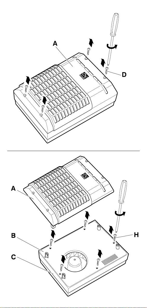
1) Remove the protection grid A) from flange B) after loosening scre ws D)
(Fig. 1).
2) Remove flange B) from the motor suppor t C) after loosening screws H)
(Fig. 1-2).
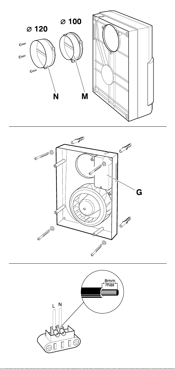
3) Fit the nozzle M) (Ø 100) or N) (Ø 120) on the motor suppor t C) close to
the delivery hole using the scre ws provided in the accessories bag (Fig. 3).
4) Install the motor suppor t C) next to the delivery hole using the screw
anchors provided in the accessor ies bag (Fig. 4).
5) Perform the electric connections (Fig. 5), tighten the electr ical cord using
the cable clamps provided and reinstall flange B) and g rille A), making
sure that the screws are correctly tightened.
Maintenance
All units come with a mechanical filter fitted on the intak e port.
This filter must be cleaned following the procedure described here below.
1) Remove the filter support E) from the unit following the instructions
provided in Fig. 7).
2) Disassemble the metal filter F) from the filter suppor t E) (Fig. 8), being
careful not to deform it. Wash it with detergent or in the washing machine.
3) Carefully clean the filter suppor t E) and reassemble it in its location.
Page 8

10
FOR G.B.
a) Light switch
b) Ceiling rose
c) Light fitting
Fig. 9
Page 9

25
– Per cavo a sezione circolare Tipo H03 VV-F
– For circular section cable Type H05 VV-F
– Pour cable à section circulaire Type H03 VV-F
– Bei rundem Kabel Typ H03 VV-F
– Para cable de secciòn circular Tipo H03 VV-F
– Para cabo com secção circular Tipo H03 VV-F
– Voor een ronde kabel Type H03 VV-F
– Vid runda ledningar Typ H03 VV-F
– Per cavo a sezione piatta Tipo H03 VVH2-F
– For flat section cable Type H05 VVH2-F
– Pour cable à section plate Type H03 VVH2-F
– Bei flachem Kabel Typ H03 VVH2-F
– Para cable de secciòn piana Tipo H03 VVH2-F
– Para cabo com secção chata Tipo H02VV-F
– Voor een platte kabel Type H03 VVH2-F
– Vid flata ledningar Typ H03 VVH2-F
Posizionamento per dispositivo fermacavo
Positioning fot cable fastener device
Positionnement pour dispositif arrèt-câble
Wervendung der Zusentiastung
Colocacion para el dispositivo de paro del cable
Posicionamiento para dispositivo segura-cabo
Plaatsing van de Trekontiasting
Positionering för kabelhällaranordning
Page 10

26
B
Dito di prova
Finger gauge
Doigt d’essai
Prüffinger
Calibre de ensayo en forma de dedo
Dedo de prova
Vingervorming mechanism element
Fingerformat mitt
A
B
C
E
D
Piano d’arresto
Stop plate
Plaque d’arrèt
Anschlagplatte
Piano de parada
Piano de paragem
Stoplaat
Anslagsplatta
Sezione
Section
Copue
Schnitt
Seccion
Secção
Doorsnede
Sektion
Isolante
Insulating material
Matière isolante
Isoliermaterial
Material aislante
Isolante
Isolatre materiaal
Isolermaterial
Sferico
Spherical
Spherique
Kugelig
Esferico
Esférico
Sfrerisch
Kulformig
Cilindrico
Cylindrical
Cylindrique
Zylindrisch
Cilindrico
Cilindrico
Cylindrisch
Cylindrisk
A
BDCE
 Loading...