

Page 1
Libretto istruzioni
Instructions Booklet
Livret d’istructions
Betriebsanleitung
Manual de instrucciones
Brugervejledning
说明手册
Használati utasítás
VORT HRW 20 MONO
VORT HRW 20 MONO RC
VORT HRW 20 MONO HCS
COD. 5.471.084.648 28/03/2017
VORTICE LIMITED
Beeches House - Eastern Avenue
Burton on Trent
DE13 0BB
Tel. (+44) 1283-492949
Fax (+44) 1283-544121
UNITED KINGDOM
VORTICE FRANCE
15-33, Rue Le Corbusier Europarc
CS 30007
90046 CRETEIL CEDEX
FRANCE
VORTICE ELETTROSOCIALI S.p.A.
Strada Cerca, 2 - frazione di Zoate
20067 TRIBIANO (MI)
Tel. (+39) 02-90.69.91
Fax (+39) 02-90.64.625
ITALIA
Page 2
Prima di usare il prodotto leggere attentamente
le istruzioni contenute nel presente libretto.
Vortice non potrà essere ritenuta responsabile per
eventuali danni a persone o cose causati dal mancato
rispetto delle indicazioni di seguito elencate, la cui
osservanza assicurerà invece la durata e l’affidabilità,
elettrica e meccanica, dell’apparecchio.
Conservare sempre questo libretto istruzioni.
Read the instructions contained in this booklet
Vortice cannot assume any responsibility for damage to
property or personal injury resulting from failure to abide
Following these instructions will ensure a long service life
responsable des dommages éventuels causés aux
personnes ou aux choses par suite du non-respect
Le respect de toutes les indications reportées dans ce
livret garantira une longue durée de vie ainsi que la
Vor Installation und Anschluss dieses Produkts müssen die
vorliegenden Anleitungen aufmerksam durchgelesen werden.
Verantwortung gezogen werden, die auf eine Nichtbeachtung
zurückzuführen sind. Befolgen Sie alle Anweisungen, um eine
lange Lebensdauer sowie die elektrische und mechanische
carefully before using the appliance.
by the instructions given in this booklet.
and overall electrical and mechanical reliability.
Keep this instruction booklet in a safe place.
Avant d'utiliser le produit, lire attentivement les
instructions contenues dans cette notice.
La société Vortice ne pourra être tenue pour
desinstructions ci-dessous.
fiabilité électrique et mécanique de l'appareil.
Conserver toujours ce livret d'instructions.
Vortice kann nicht für Personen- oder Sachschäden zur
der Hinweise in dieser Betriebsanleitung
Zuverlässigkeit des Geräts zu gewährleisten.
Diese Betriebsanleitung ist gut aufzubewahren.
Antes de usar el producto, leer atentamente
las instrucciones de este manual.
Vortice no es responsable de los eventuales daños
ocasionados a personas o cosas como resultado del
incumplimiento de las indicaciones de este manual,
las cuales garantizan la durabilidad y fiabilidad eléc-
trica y mecánica del aparato.
Guardar siempre este manual de instrucciones.
Før apparatet tages i brug, skal denne vejledning læses
grundigt igennem.
Vortice kan ikke betragtes som ansvarlig for eventuelle
skader på personer eller ting forårsaget af manglende
overholdelse af anvisningerne i denne brugervejledning,
som apparatets sikre og vedvarende elektriske og
mekaniske funktion afhænger af.
Opbevar altid denne brugervejledning
使用产品前,请先仔细阅读这些说明。
Vortice对于不遵守本手册中的注意事项和警告
而造成的人员伤害或物质损失概不负责。
请遵守手册中的所有指示执行,以保证
设备电器及机械部件的寿命和可靠性。
请妥善保存本说明手册
A termék használata előtt gondosan olvassa el a kézikönyvben
tartalmazott utasításokat. A Vortice nem vonható felelősségre
olyan esetleges személyi sérülésekért vagy anyagi károkért,
amelyeket az alábbiakban felsorolt utasítások be nem tartása
okozott. Betartása viszont garantálja a berendezés élettartamát
valamint az elektromos és mechanikus megbízhatóságát.
Ő
rizze meg a használati utasítást.
。
Indice IT
Descrizione ed impiego . . . . . . . . . . . . . . . . . . . . . . . . 3
Sicurezza . . . . . . . . . . . . . . . . . . . . . . . . . . . . . . . . . . . 3
Struttura e dotazione . . . . . . . . . . . . . . . . . . . . . . . . . . 4
Installazione . . . . . . . . . . . . . . . . . . . . . . . . . . . . . . . . 5
Utilizzo . . . . . . . . . . . . . . . . . . . . . . . . . . . . . . . . . . . . 12
Schemi di collegamento . . . . . . . . . . . . . . . . . . . . . . 13
Manutenzione/pulizia. . . . . . . . . . . . . . . . . . . . . . . . . 14
Informazione importante per lo
smaltimento ambientalmente compatibile. . . . . . . . . 15
Index EN
Description and use. . . . . . . . . . . . . . . . . . . . . . . . . . 16
Safety. . . . . . . . . . . . . . . . . . . . . . . . . . . . . . . . . . . . . 16
Items supplied . . . . . . . . . . . . . . . . . . . . . . . . . . . . . . 17
Installation . . . . . . . . . . . . . . . . . . . . . . . . . . . . . . . . . 18
Use. . . . . . . . . . . . . . . . . . . . . . . . . . . . . . . . . . . . . . . 25
Wiring diagrams. . . . . . . . . . . . . . . . . . . . . . . . . . . . . 26
Maintenance/cleaning . . . . . . . . . . . . . . . . . . . . . . . . 27
Important information regarding
eco-compatible disposal . . . . . . . . . . . . . . . . . . . . 28
Index FR
Description et mode d’emploi . . . . . . . . . . . . . . . . . . 29
Sécurité . . . . . . . . . . . . . . . . . . . . . . . . . . . . . . . . . . . 29
Structure et équipement de série . . . . . . . . . . . . . . . 30
Installation . . . . . . . . . . . . . . . . . . . . . . . . . . . . . . . . . 31
Mode d’emploi. . . . . . . . . . . . . . . . . . . . . . . . . . . . . . 38
Schemas de branchement. . . . . . . . . . . . . . . . . . . . . 39
Entretien / nettoyage . . . . . . . . . . . . . . . . . . . . . . . . . 40
Information importante pour éliminer
l’appareil en respectant l’environnement. . . . . . . . . . 41
Betriebsanleitung DE
Beschreibung und gebrauch . . . . . . . . . . . . . . . . . . . 42
Sicherheit. . . . . . . . . . . . . . . . . . . . . . . . . . . . . . . . . . 42
Aufbau und Ausstattung . . . . . . . . . . . . . . . . . . . . . . 43
Installation . . . . . . . . . . . . . . . . . . . . . . . . . . . . . . . . . 44
Gebrauch . . . . . . . . . . . . . . . . . . . . . . . . . . . . . . . . . . 51
Anchlusspläne . . . . . . . . . . . . . . . . . . . . . . . . . . . . . . 52
Wartung / Reinigung . . . . . . . . . . . . . . . . . . . . . . . . . 53
Wichtige Information für eine
umweltgerechte Entsorgung . . . . . . . . . . . . . . . . . . . 54
Índice ES
Descripción y uso . . . . . . . . . . . . . . . . . . . . . . . . . . . 55
Seguridad . . . . . . . . . . . . . . . . . . . . . . . . . . . . . . . . . 55
Estructura y dotación. . . . . . . . . . . . . . . . . . . . . . . . . 56
Instalación . . . . . . . . . . . . . . . . . . . . . . . . . . . . . . . . . 57
Uso. . . . . . . . . . . . . . . . . . . . . . . . . . . . . . . . . . . . . . . 64
Esquemas de conexión . . . . . . . . . . . . . . . . . . . . . . . 65
Mantenimiento y limpieza . . . . . . . . . . . . . . . . . . . . . 66
Información importante sobre
eliminación compatible con el medio ambiente . . . . 67
Indeks DA
Beskrivelse og brug . . . . . . . . . . . . . . . . . . . . . . . . . . 68
Sikkerhed . . . . . . . . . . . . . . . . . . . . . . . . . . . . . . . . . . 68
Struktur og tilbehør. . . . . . . . . . . . . . . . . . . . . . . . . . . 69
Installation. . . . . . . . . . . . . . . . . . . . . . . . . . . . . . . . . . 70
Anvendelse . . . . . . . . . . . . . . . . . . . . . . . . . . . . . . . . . 77
Forbindelsesdiagram . . . . . . . . . . . . . . . . . . . . . . . . . 78
Vedligeholdelse / rengøring . . . . . . . . . . . . . . . . . . . . 79
Vigtige oplysninger om miljøvenlig bortskaffelse . . . . 80
目录
ZH
使用说明. . . . . . . . . . . . . . . . . . . . . . . . . . . . . . . . . . . 81
安全 . . . . . . . . . . . . . . . . . . . . . . . . . . . . . . . . . . . . . . 81
组成与配备 . . . . . . . . . . . . . . . . . . . . . . . . . . . . . . . . . 82
安装 . . . . . . . . . . . . . . . . . . . . . . . . . . . . . . . . . . . . . . 83
使用方法. . . . . . . . . . . . . . . . . . . . . . . . . . . . . . . . . . . 90
接线图 . . . . . . . . . . . . . . . . . . . . . . . . . . . . . . . . . . . . 91
保养与清洁 . . . . . . . . . . . . . . . . . . . . . . . . . . . . . . . . . 92
Tartalomjegyzék HU
Leírás és működés . . . . . . . . . . . . . . . . . . . . . . . . . . . 94
Biztonság . . . . . . . . . . . . . . . . . . . . . . . . . . . . . . . . . . 94
Szerkezet és berendezések . . . . . . . . . . . . . . . . . . . . 95
Telepítés . . . . . . . . . . . . . . . . . . . . . . . . . . . . . . . . . . . 96
Használat . . . . . . . . . . . . . . . . . . . . . . . . . . . . . . . . . 103
Kapcsolási rajzok . . . . . . . . . . . . . . . . . . . . . . . . . . . 104
Karbantartás/tisztítás . . . . . . . . . . . . . . . . . . . . . . . . 105
Fontos információ
a kompatibilis környezetvédelmi ártalmatlanításhoz 106
2
Page 3
ITALIANO
Descrizione ed impiego
Vort HRW 20 MONO (nel seguito “l’apparecchio”) è un sistema di ventilazione decentralizzato a recupero di calore,
installabile a parete in muri perimetrali di spessore compreso tra 285 mm e 700 mm. L’apparecchio è realizzato in due
versioni:
Vort HRW 20: modello con scheda elettronica, comandi e led di diagnostica integrati;
Vort HRW 20 RC: modello con gruppo comandi esterno, contenente la scheda elettronica, i comandi e il led di
diagnostica. Il gruppo comandi può gestire fino a 4 apparecchi contemporaneamente.
(Vedere “Struttura e dotazione “ e “Utilizzo” per una descrizione dettagliata delle varie componenti e funzioni ). Questi
apparecchi sono particolarmente adatti ad un funzionamento in continuo.
Questi apparecchi possono funzionare anche se collegati a sensori opzionali di temperatura ed umidità relativa (C TEMP
e C HCS)
Vort HRW 20 HCS: modello con scheda elettronica, comandi e led di diagnostica integrati, sensore di umidità relativa
integrato.
Questi apparecchi sono stati progettati per un uso in ambiente domestico e commerciale.
Sicurezza
Attenzione:
questo simbolo indica che è necessario
!
prendere precauzioni per evitare danni all’utente
• Seguire le istruzioni di sicurezza, per evitare danni all’utente.
• Non utilizzare l’apparecchio per una funzione differente da quella esposta in questo libretto.
• Dopo aver tolto il prodotto dal suo imballo, assicurarsi della sua integrità: nel dubbio rivolgersi a persona
professionalmente qualificata o ad un Centro Assistenza Tecnica autorizzato Vortice.
• Non lasciare parti dell’imballo alla portata di bambini o persone diversamente abili.
• L’uso di qualsiasi apparecchio elettrico comporta l’osservanza di alcune regole fondamentali, tra le quali: non toccarlo
con mani bagnate o umide; non toccarlo a piedi nudi.
• Non utilizzare l'apparecchio in presenza di sostanze o vapori infiammabili come alcool, insetticidi, benzina, ecc.
• Riporre l’apparecchio lontano da bambini e da persona diversamente abile, nel momento in cui si decide di scollegarlo
dalla rete elettrica e di non utilizzarlo più.
• Prendere precauzioni al fine di evitare che nel locale vi sia riflusso di gas dalla canna di scarico o da altri apparecchi a
fuoco aperto.
• Questo apparecchio può essere utilizzato da bambini di età non inferiore a 8 anni e da persone con
ridotte capacità fisiche, sensoriali o mentali, o prive di esperienza o della necessaria conoscenza,
purché sotto sorveglianza oppure dopo che le stesse abbiano ricevuto istruzioni relative all’uso
sicuro dell’apparecchio e alla comprensione dei pericoli ad esso inerenti. I bambini non devono
giocare con l'apparecchio. La pulizia e la manutenzione destinata ad essere effettuata
dall’utilizzatore non deve essere effettuata da bambini senza sorveglianza.
Avvertenza:
questo simbolo indica che è necessario
!
prendere precauzioni per evitare danni al prodotto
• Non apportare modifiche di alcun genere all’apparecchio.
• Le istruzioni per la manutenzione devono essere seguite per prevenire danni e/o usura eccessiva dell’apparecchio.
• Non lasciare l'apparecchio esposto ad agenti atmosferici (pioggia, sole, ecc.).
• Non appoggiare oggetti sull’apparecchio.
• La pulizia interna del prodotto deve essere eseguita soltanto da personale qualificato.
• Verificare periodicamente l'integrità dell'apparecchio. In caso di imperfezioni, non utilizzare l'apparecchio e contattare
subito un Centro di Assistenza Tecnica autorizzato Vortice.
• In caso di cattivo funzionamento e/o guasto dell'apparecchio, rivolgersi subito ad un Centro Assistenza Tecnica
autorizzato Vortice e richiedere, per l’eventuale riparazione, l'uso di ricambi originali Vortice.
• Se il prodotto cade o riceve forti colpi farlo verificare subito presso un Centro di Assistenza Tecnica autorizzato Vortice.
• L’apparecchio deve essere montato in modo da garantire che, in condizioni normali di funzionamento, nessuno possa
venirsi a trovare in prossimità di parti in movimento o sotto tensione.
• Nel caso di: smontaggio dell’apparecchio, con strumenti appropriati; estrazione dello scambiatore di calore; estrazione
del modulo dei motori; l’apparecchio dovrà essere preventivamente spento e disconnesso dalla rete di alimentazione
elettrica.
• L'impianto elettrico a cui è collegato il prodotto deve essere conforme alle norme vigenti.
• Collegare l'apparecchio alla rete di alimentazione /presa elettrica solo se la portata dell'impianto /presa è adeguata alla
3
Page 4
ITALIANO
A A
A
HRW 20
HRW 20 RC
sua potenza massima. In caso contrario rivolgersi subito a personale professionalmente qualificato.
• Spegnere l’interruttore generale dell’impianto quando: si rileva un’anomalia di funzionamento; si decide di eseguire una
manutenzione di pulizia esterna; si decide di non utilizzare per brevi o lunghi periodi l’apparecchio.
• Il flusso d’aria estratto deve essere pulito, (cioè privo di elementi grassi, fuliggine, agenti chimici e corrosivi o miscele
esplosive ed infiammabili).
• Non coprire e non ostruire l’aspirazione e la mandata dell’apparecchio, in modo da assicurare l'ottimale passaggio
dell'aria.
• Temperatura massima di esercizio: 45°C.
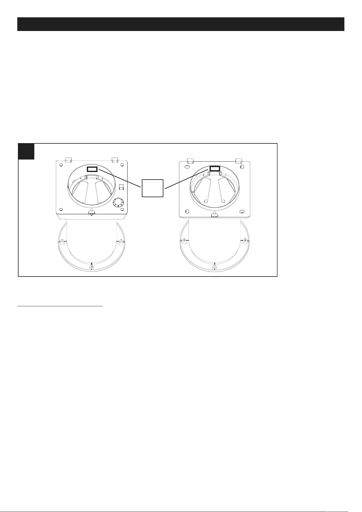
• I dati elettrici della rete devono corrispondere a quelli riportati in targa A (fig.A).
• L’installazione dell’apparecchio deve essere effettuata da parte di personale professionalmente
qualificato.
• Per l'installazione occorre prevedere un interruttore onnipolare con distanza di apertura dei contatti
uguale o superiore a mm 3.
HRW 20 / HRW 20 HCS HRW 20 RC
Struttura e dotazione
Le principali parti componenti dell’apparecchio sono:
• involucro in polipropilene espanso;
• pannello interno in polimero plastico autoestinguente, rivestito con materiale termoisolante;
• griglia esterna in gomma, montabile esternamente tramite tasselli o inseribile internamente attraverso il foro del muro
senza necessità di ponteggio esterno;
• rete anti insetti, inseribile nel condotto insieme alla griglia esterna;
• motoventilatore EC alimentato a bassa tensione
• scambiatore di calore di tipo ad accumulo, realizzato in materiale ceramico
• filtro G3 lavabile;
• prefiltro lavabile;
• tubo per installazione all’interno di muri di spessore da 285 a 700 mm (opzionale);
4
Page 5
ITALIANO
1 1
IN
OUT
33
44
2 2
mm 162
ø
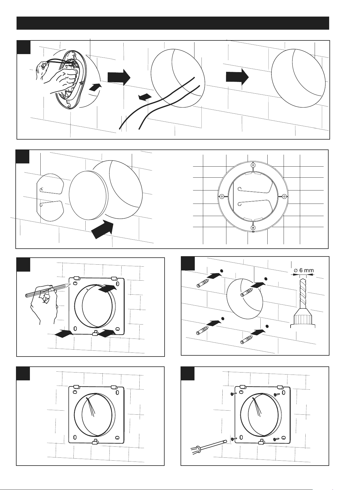
Installazione
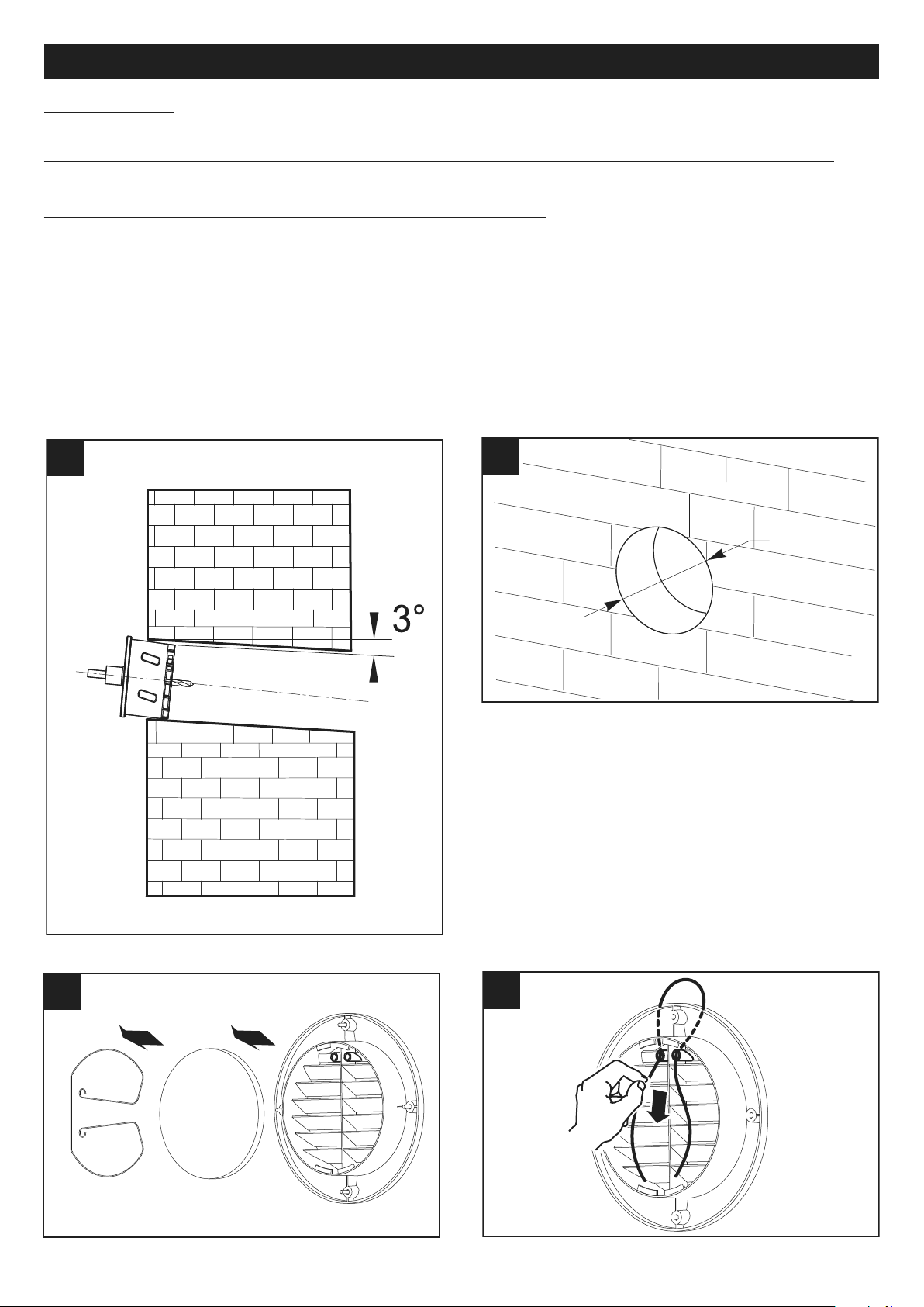
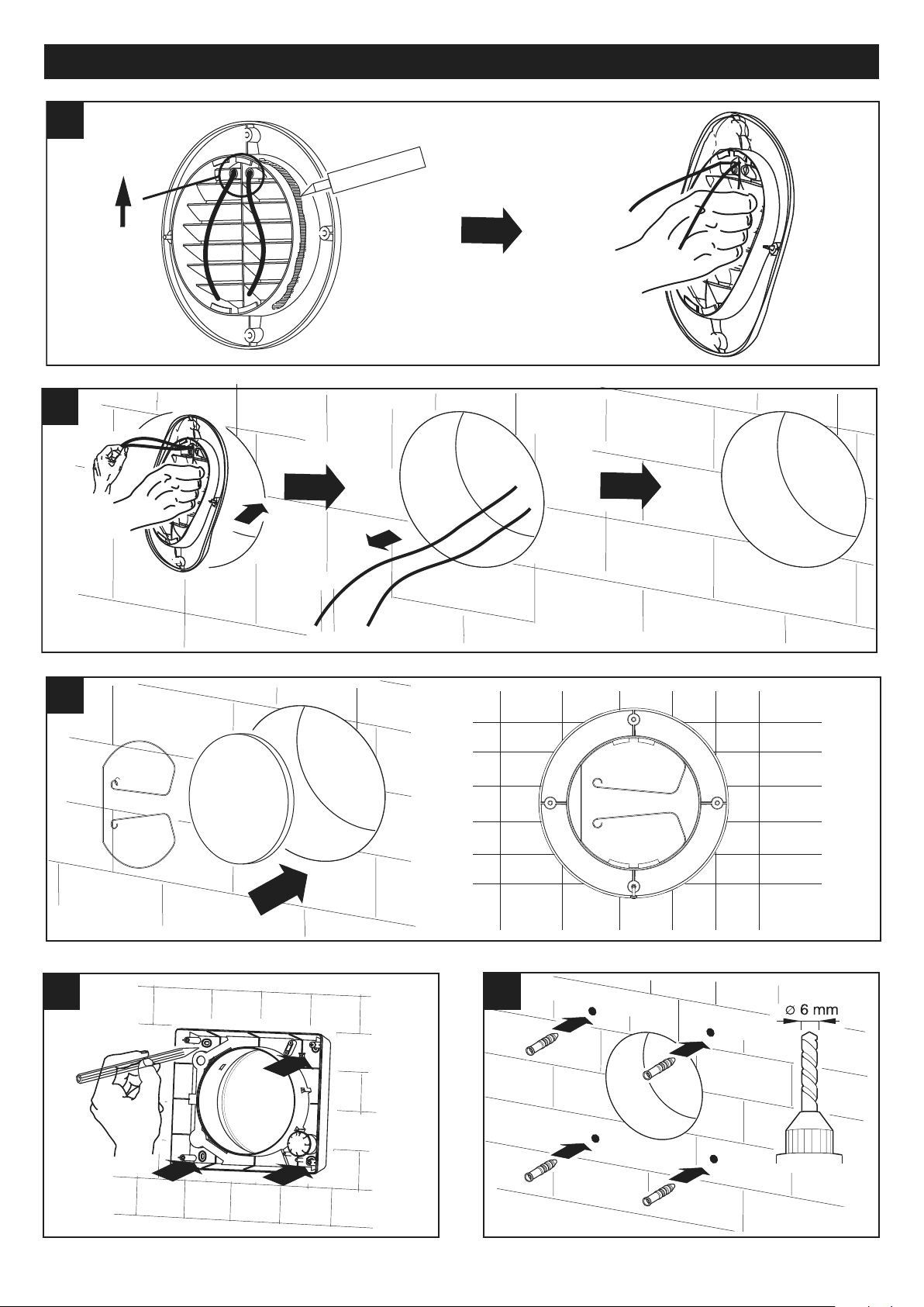
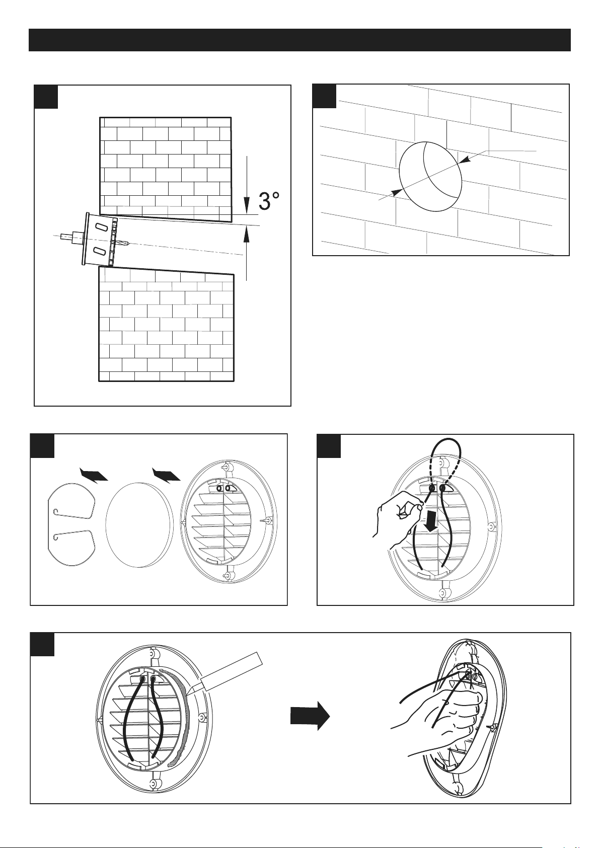
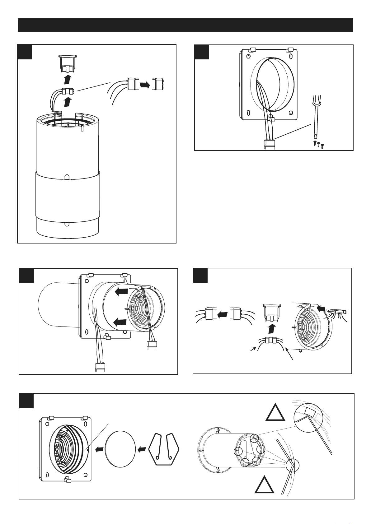
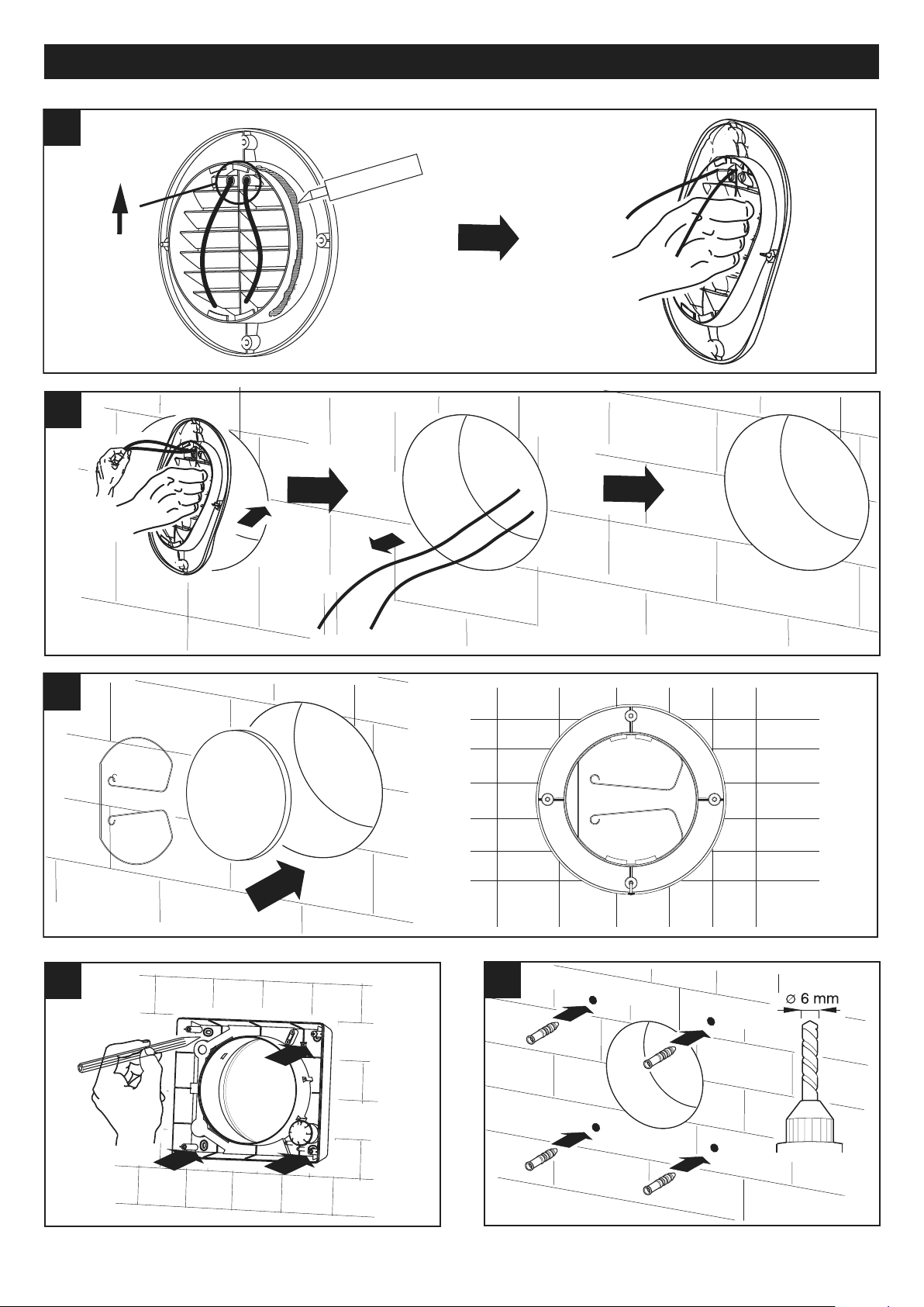
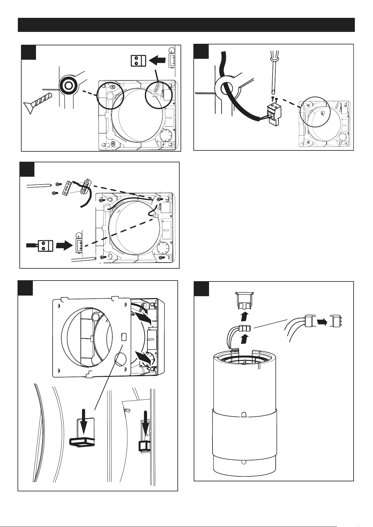
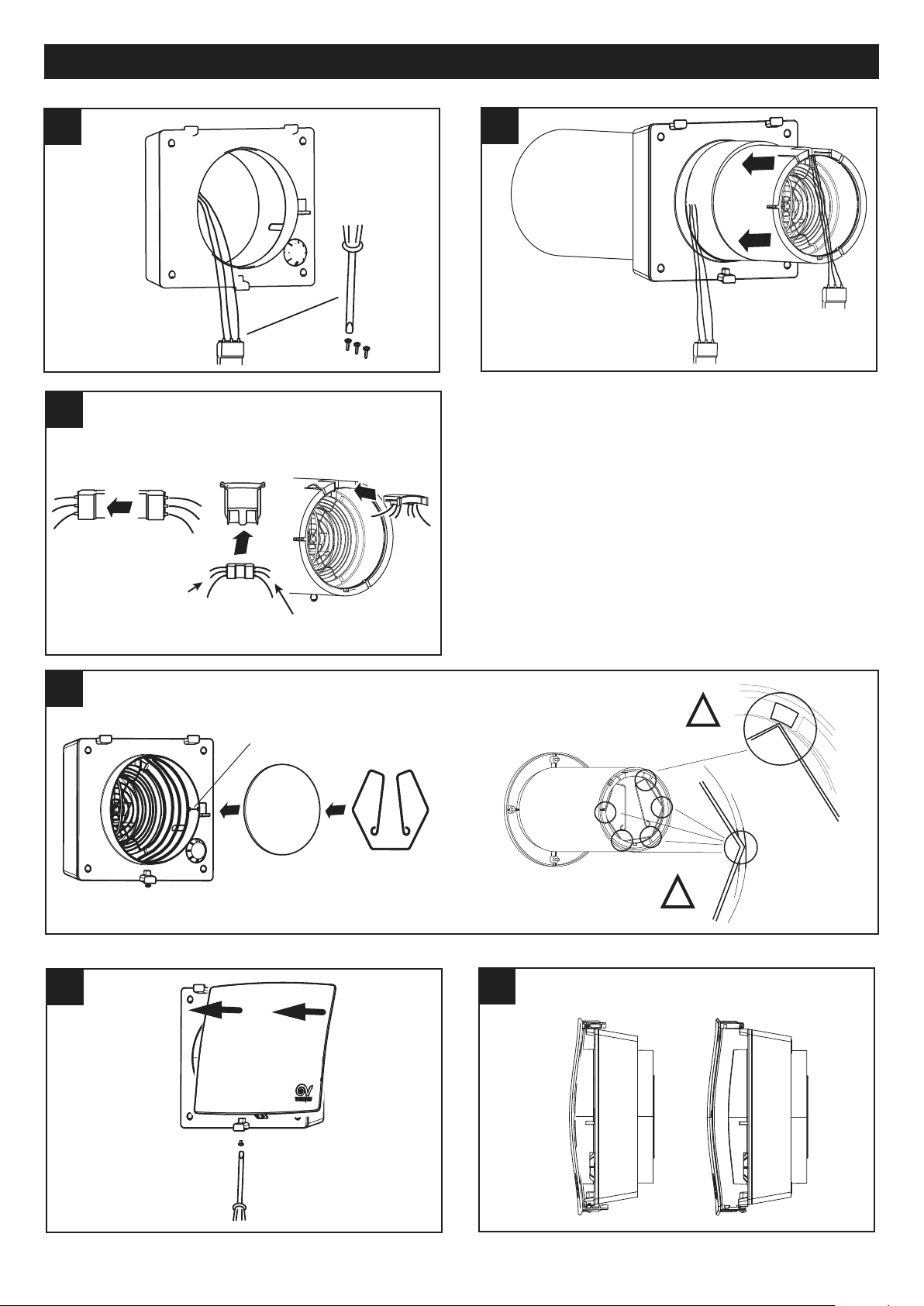
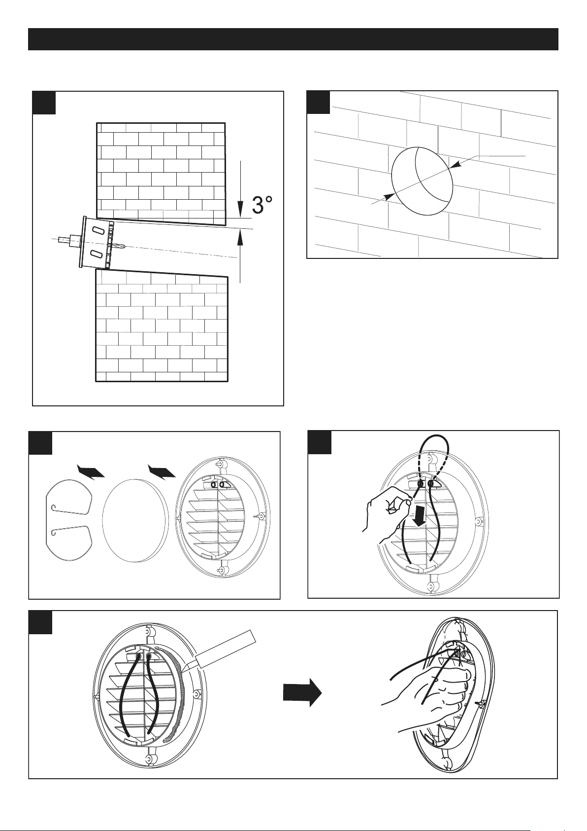
Fig 1 ÷ 38
N.B. Prima di procedere con l’installazione rimuovere l’imballo interno di protezione presente nel prodotto.
N.B. Prima di procedere con l’installazione rimuovere i distanziali presenti all’interno del tubo di installazione in
PVC, e tagliare lo stesso nella misura adatta allo spessore del muro.
L’installazione deve essere realizzata seguendo le norme di sicurezza in vigore nel paese di destinazione, e le istruzioni
del presente libretto.
L’apparecchio deve essere montato all’interno di un muro perimetrale con uno spessore di almeno 285 mm.
N.B. Per il corretto funzionamento dell’apparecchio, questo deve essere installato con la sede per il connettore
posizionata in alto, come in fig. 16
VORT HRW 20 / VORT HRW 20 HCS
5
Page 6
77
8 8
9 9
ITALIANO
55
G
LUE
UP
6 6
6
Page 7
ITALIANO
10 10
11 11
12 12
13 13
14 14
7
Page 8
19 19
20 20
A B
ITALIANO
15 15
16 16
17 17
FROM
ELECTRONIC
BOARD
MOTOR
18 18
20 mm
!
!
8
Page 9
ITALIANO
2323
2424
2525
GLU
E
21 21
IN
OUT
22 22
mm 162
ø
VORT HRW 20 RC
9
Page 10

ITALIANO
2727
28 28
29 29
30 30
150 mm
31 31
26 26
10
Page 11
ITALIANO
32 32
33 33
34 34
35 35
FROM
ELECTRONIC
BOARD
MOTOR
36 36
20 mm
!
!
11
Page 12
ITALIANO
A
B
REC
ESTR
MAND
C
39 39
A
B
E/M
REC
C
MAND
ESTR
D
40 40
3737
38 38
A B
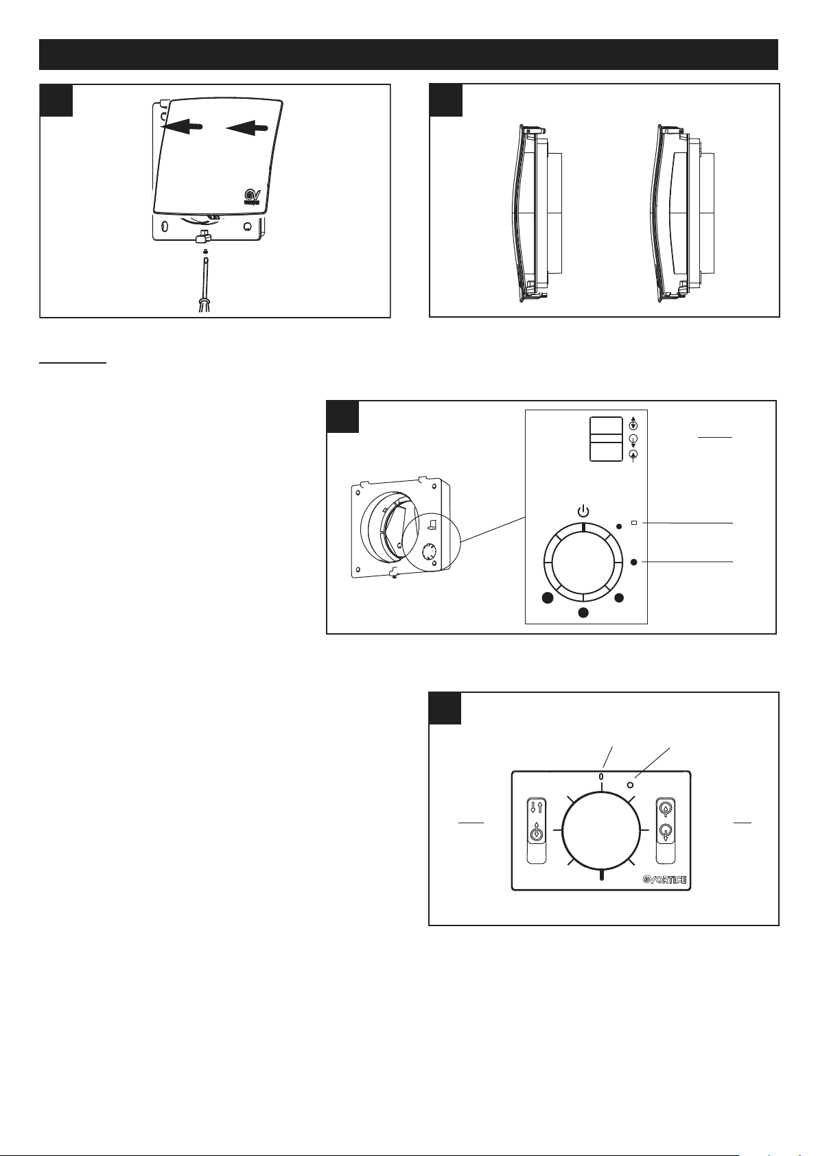
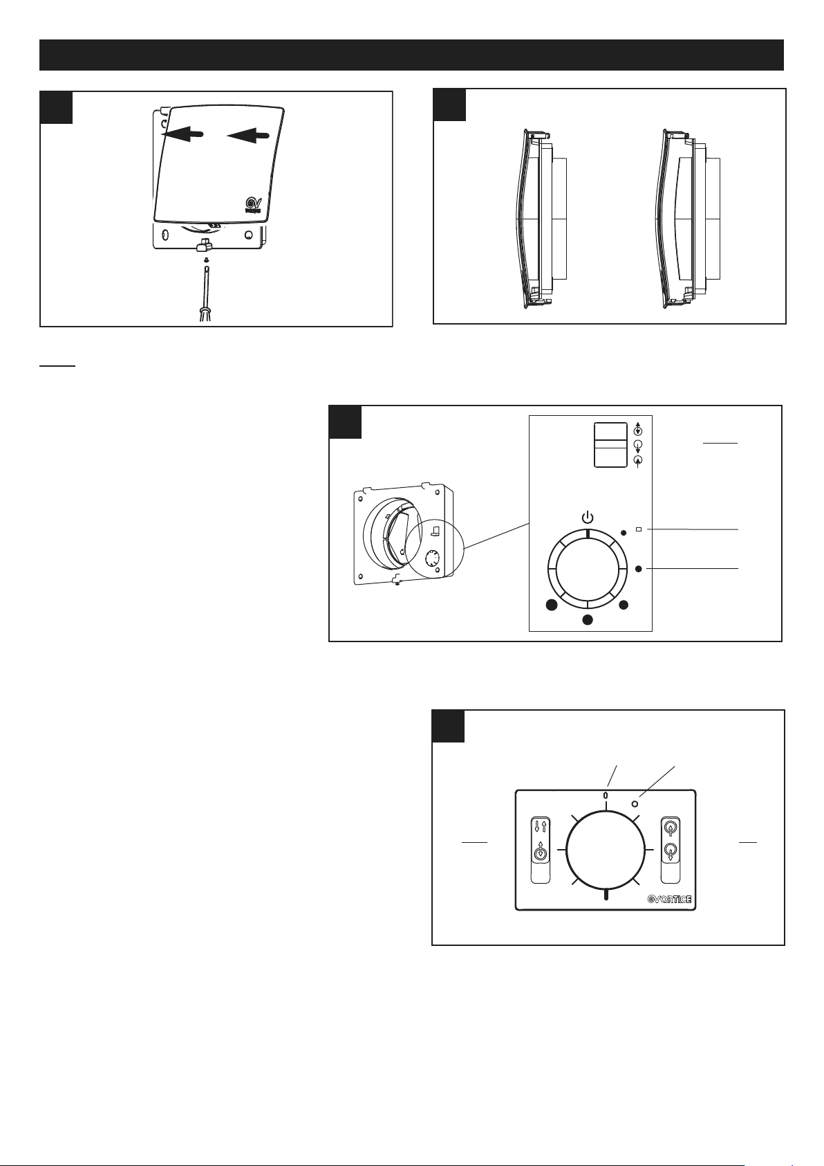
Utilizzo
Vort HRW 20
L’apparecchio viene controllato tramite i
comandi a bordo (fig.39):
• A: selettore a 6 posizioni:
0: stand by, apparecchio spento
1-5: velocità/portata da min a max
• B: selettore a 3 posizioni:
REC: recupero calore (il sistema opera
come un recuperatore, con inversione
ciclica del senso di rotazione ogni 50-80100 s circa)
ESTR: estrazione (il sistema opera come un
ventilatore, con estrazione aria dal locale)
MAND: mandata (il sistema opera come un
ventilatore, con immissione aria del locale)
Un led (C ) indica lo stato dei filtri:
• led spento: filtri puliti
• led acceso: filtri da pulire o sostituire
Vort HRW 20 RC
L’apparecchio (da 1 a 4) viene controllato tramite il comando
remoto cablato (fig.40):
• A: selettore a 6 posizioni:
0: stand by, apparecchio spento
1-5: portata da min a max
• B: selettore a 2 posizioni:
REC: recupero calore (il sistema opera come un
recuperatore, con inversione ciclica del senso di rotazione
ogni 50-80-100 s circa)
E/M: estrazione/mandata
• C: selettore a 2 posizioni (qualora sia stato selezionato E/M
sul selettore B:
ESTR: estrazione (il sistema opera come un ventilatore, con
estrazione aria dal locale)
MAND: mandata (il sistema opera come un ventilatore, con
immissione aria dal locale)
Un led (D ) indica lo stato dei filtri:
• led spento: filtri puliti
• led acceso: filtri da pulire o sostituire
Nel caso in cui al comando remoto siano collegate 2,3,4 unità, tali unità verranno pilotate in modo tale da garantire il
bilanciamento della portata complessiva in modalità di ventilazione con recupero di calore.
In caso di 3 unità collegate il bilanciamento potrebbe comportare lo spegnimento a rotazione di due delle tre unità
(in funzione della velocità impostata).
12
Page 13
ITALIANO
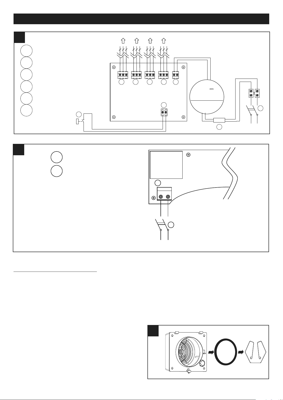
NL
~230V
Mains
1
1
3
3
NL
J 1
2
2
J4
4
4
42 42
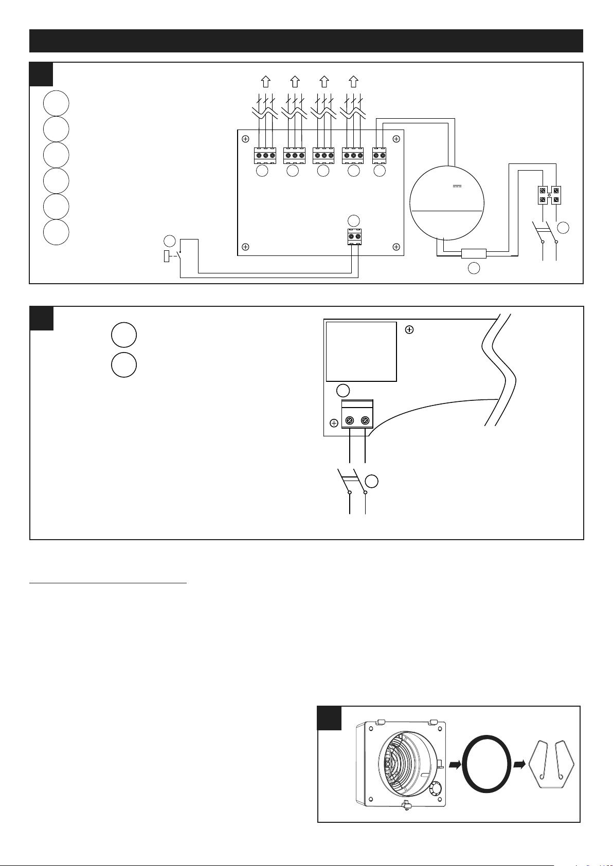
VORT HRW 20 MONO
Morsettiera PCB estraibile
Morsettiera PCB fissa
Interruttore di linea a 2 poli
Contatto privo di potenziale
(interruttore o relay remoti)
43
43
VORT HRW 20 MONO RC
1 FAN header terminal block
2
FAN plug terminal block
RD
VT
BU
3
3
21
VORT HRW 20 MONO RC FAN
TO REMOTE CONTROL (HRW )
16 -24 AW G
0.35-1mm
2
-C+
4141
6
0708090
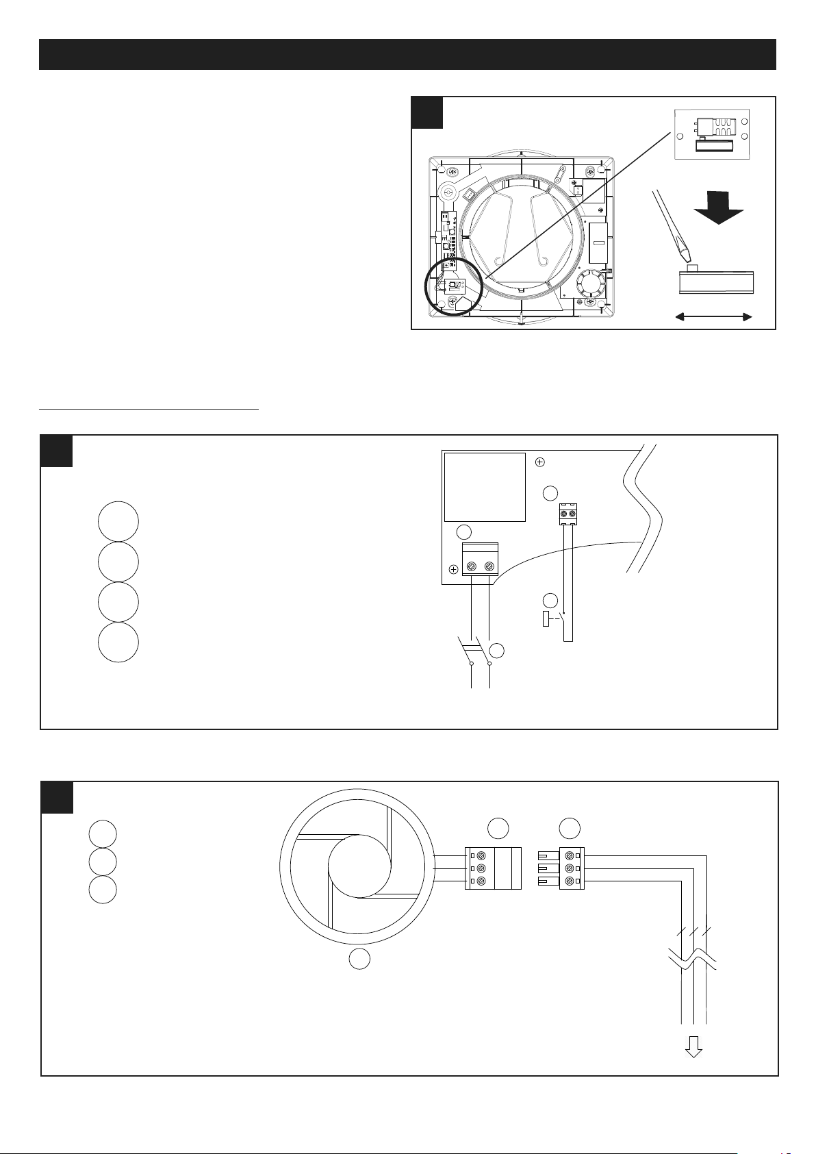
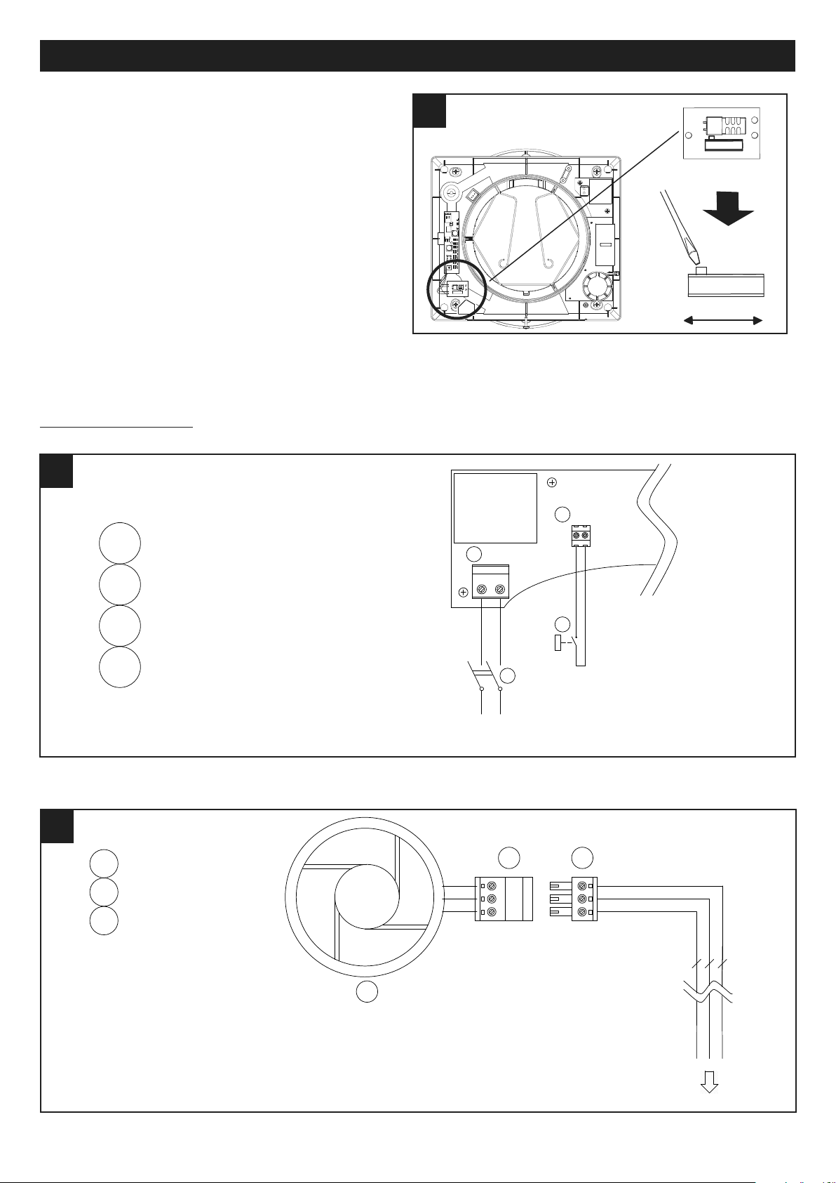
Vort HRW 20 HCS
Questo modello è dotato di un circuito rilevatore dell’umidità
relativa, preimpostato in fabbrica sul valore 70%; quando
l’umidità relativa supera tale valore di soglia l’apparecchio si
attiva automaticamente.
Tale soglia è comunque impostabile da parte dell’installatore su 4 valori (tramite slide-switch come in fig.41): 60%,
70%, 80%, 90% .
Quando il sensore attiva l’apparecchio, questo entra in mo-
alità estrazione alla massima velocità finchè l'umidità am-
d
biente non scende sotto il valore di soglia. Una volta che
l'umidità è scesa sotto il valore di soglia, l’apparecchio riprende a funzionare come in precedenza, Il sensore ha effetto anche a macchina in stand-by, cioè con selettore di
velocità nella posizione 0.
Schemi di collegamento
Morsetto femmina
del ventilatore
Morsetto maschio
dalla scheda elettr.
Ventola
13
Page 14
ITALIANO
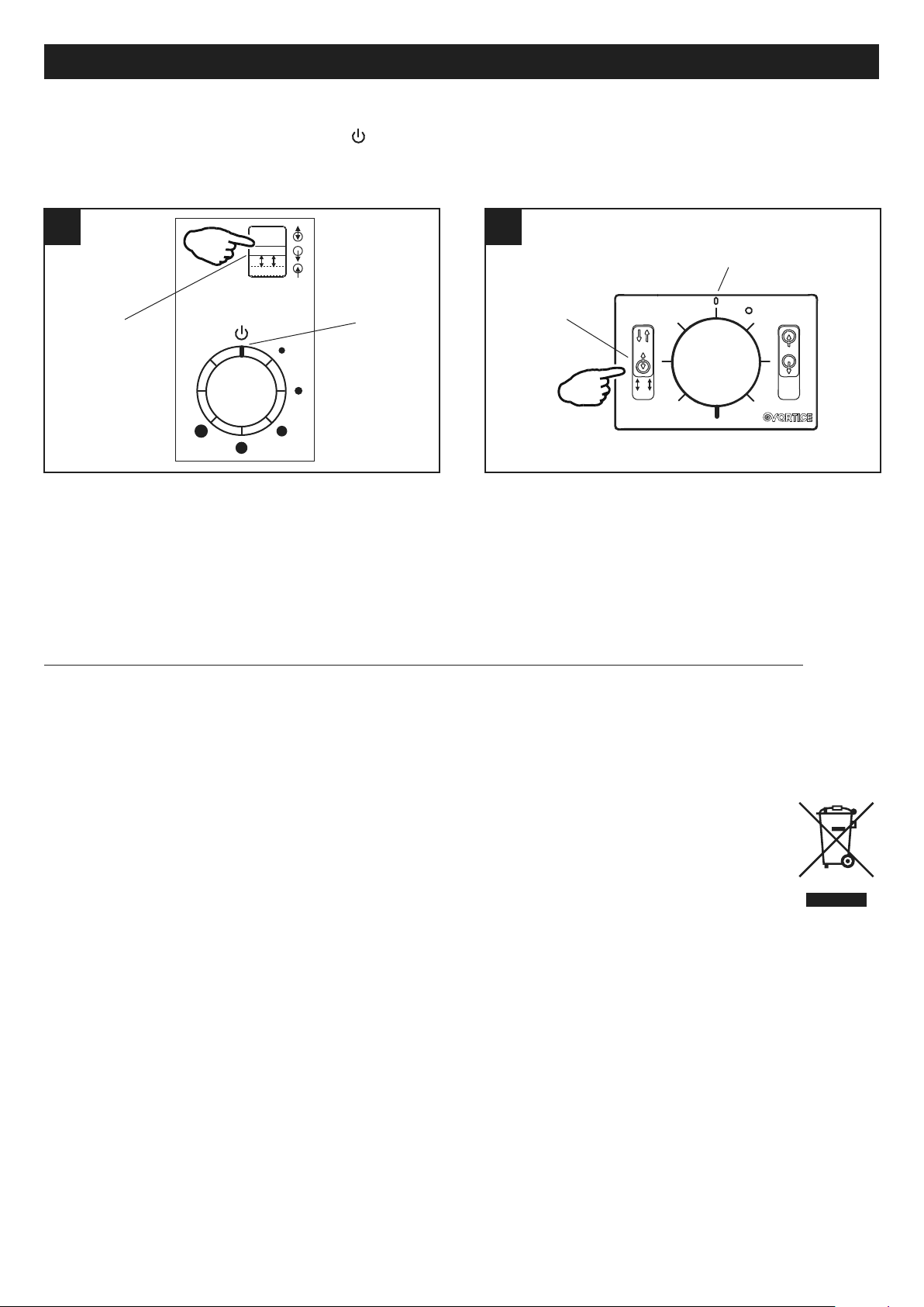
1
VORT HRW 20 MONO RC
FAN #1 to #4 PCB terminal block
4
Mains 2 poles switch
2
12V Power Supply PCB terminal block
5
Dry contact (remote switch / relay )
3
Remote input PCB terminal block
44 44
REMOTE CONTROL
6
Ferrite
TO VORT HRW 20 MONO RC FAN
5
NL
230V ~50Hz
8 9
10 11
J1J5J6J7J8
J3
REMOTE
12V
-+
#1
-+C
#2
-+C
#3
-+C
#4
-+C
V
OR-
8
2
0
~
BN
BU
230V
RD
BK
50/60Hz
BU
BN
12V
+ -
16-24 AW G
0.5-1mm
2
1 1 1 1
3
2
4
6
45
45
N L
~230V
Mains
1
1 Pluggable PCB terminal block
2
2 Mains 2 poles switch
N L
J1
VORT HRW 20 MONO HCS
Morsetti 1 ÷ 4 dalla ventola
Morsetti alimentazione 12 V
Morsetti ingresso remoto
Interruttori di linea 2 poli
Contatto privo di potenziale
(interruttore / relay remoto)
Morsetto maschio scheda elettronica
Interruttori di linea 2 poli
Manutenzione e pulizia
Prima di iniziare qualsiasi operazione accertarsi che il prodotto sia scollegato dalla rete elettrica. Lo smontaggio e relativo
montaggio sono operazioni di manutenzione straordinaria e devono essere eseguite da personale professionalmente
qualificato.
Pulizia filtri e reset indicatore stato filtri (entrambi i modelli)
Tempi consigliati per la manutenzione: In generale in funzione dell’area geografica di installazione il livello di inquinamento
dell’aria è variabile, e quindi è variabile la durata dei filtri. Tenendo presenti queste considerazioni i tempi per la
manutenzione dei filtri sono comunque preimpostatii nel modo seguente:
saturazione filtri: 12 mesi: si accende il led apposito sul display (senza blocco dell’apparecchio).
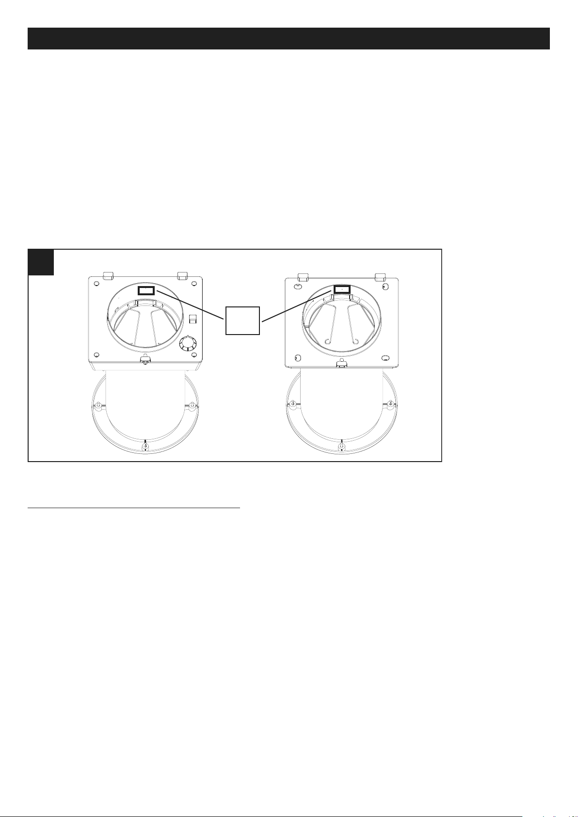
Il filtro G3 può essere pulito direttamente dall’utente,
asportandolo, lavandolo e riposizionandolo nella sua
sede con la molla. (fig 46)
14
Page 15
ITALIANO
3x
A
B
47 47
48 48
A
B
3x
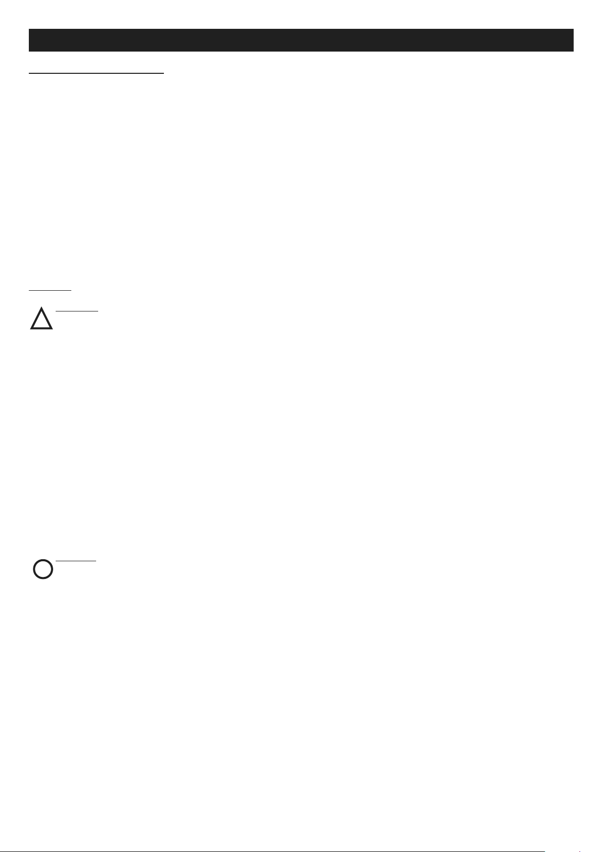
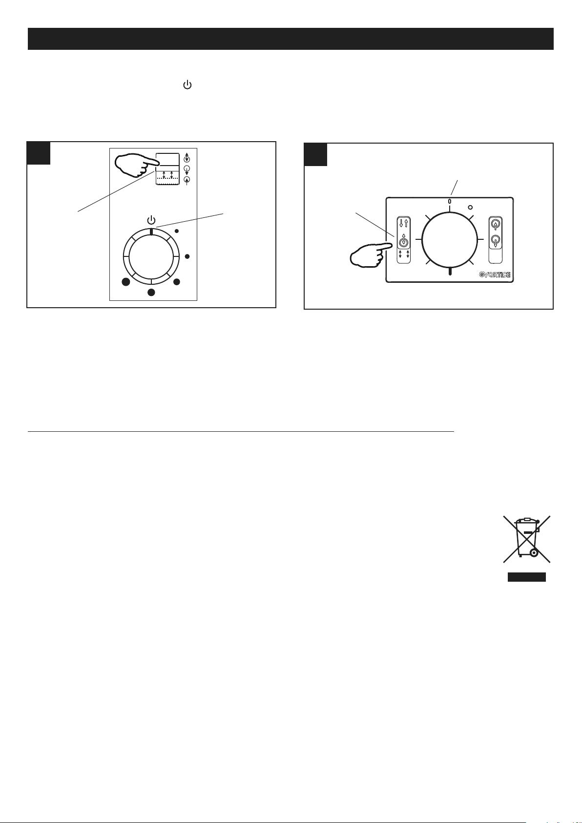
Su tutti i modelli è necessario resettare la situazione di filtro saturo (led acceso) dopo la pulizia/sostituzione del filtro
stesso, eseguendo la seguente azione:
posizionare il selettore di velocità A su “0” /
Azionare il selettore B modalità di funzionamento 3 volte consecutive entro un tempo massimo di 2s. A conferma del reset
avvenuto il led lampeggerà 3 volte e poi si spegnerà. (fig.47,48)
Si suggerisce inoltre, una volta all’anno, una pulizia accurata della macchina e dei filtri interni, attività che deve essere
richiesta ad un centro assistenza.
N.B. La mancata pulizia o sostituzione dei filtri comporta inconvenienti per l’efficienza dell’impianto, con:
- aumento delle perdite di carico nel circuito aria e riduzione di portata aria;
- conseguente diminuzione della resa della macchina e peggioramento del confort in ambiente.
Informazione importante per lo smaltimento ambientalmente compatibile
IN ALCUNI PAESI DELL'UNIONE EUROPEA QUESTO PRODOTTO NON RICADE NEL CAMPO DI APPLICAZIONE
DELLA LEGGE NAZIONALE DI RECEPIMENTO DELLA DIRETTIVA RAEE E QUINDI NON È IN ESSI VIGENTE
ALCUN OBBLIGO DI RACCOLTA DIFFERENZIATA A FINE VITA.
Questo prodotto è conforme alla Direttiva EU2002/96/EC.
Il simbolo del bidone barrato riportato sull’apparecchio indica che il prodotto, alla fine della propria vita
utile, dovendo essere trattato separatamente dai rifiuti domestici, deve essere conferito in un centro di
raccolta differenziata per apparecchiature elettriche ed elettroniche oppure riconsegnato al rivenditore al
momento dell’acquisto di una nuova apparecchiatura equivalente.
L’utente è responsabile del conferimento dell’apparecchio a fine vita alle appropriate strutture di raccolta,
pena le sanzioni previste dalla vigente legislazione sui rifiuti.
L’adeguata raccolta differenziata per l’avvio successivo dell’apparecchio dismesso al riciclaggio, al trattamento e allo
smaltimento ambientalmente compatibile contribuisce ad evitare possibili effetti negativi sull’ambiente e sulla salute e
favorisce il riciclo dei materiali di cui è composto il prodotto.
Per informazioni più dettagliate inerenti i sistemi di raccolta disponibili, rivolgersi al servizio locale di smaltimento rifiuti o
al negozio in cui è stato effettuato l’acquisto.
I produttori e gli importatori ottemperano alla loro responsabilità per il riciclaggio, il trattamento e lo smaltimento
ambientalmente compatibile sia direttamente sia partecipando ad un sistema collettivo.
15
Page 16
ENGLISH
Description and use
Vort HRW 20 MONO (hereinafter "the appliance") is a non-central ventilation system with heat recovery, which can be
installed on perimeter walls of between 285 mm and 700 mm in thickness.
The appliance is made in two versions:
Vort HRW 20: model with built-in printed circuit board, controls and diagnostic LED;
Vort HRW 20 RC: model with external control unit, containing the PCB, controls and diagnostic LED. The control unit can
handle up to 4 appliances simultaneously.
(See "Items supplied" and "Use" for a detailed description of the various components and functions).
These appliances are particularly suitable for continuous operation.
These appliances can also work when connected to optional temperature and relative humidity sensors (C TEMP and C
HCS).
Vort HRW 20 HCS: model with built-in circuit board, controls and diagnostics LED, built-in humidity sensor.
These appliances have been designed for use in residential and commercial properties.
Safety
Warning:
this symbol indicates that care must
!
be taken to avoid injury to the user
• Follow the safety instructions to prevent any harm to the user.
• Do not use this appliance for purposes other than those described in this manual.
• Having removed the appliance from its packaging, make certain that it is intact and undamaged. If in doubt, consult a
professional or contact an authorized Vortice Service Centre.
• Do not leave packaging within reach of children or individuals with disabilities.
• Certain basic rules must always be observed when using any electrical appliance: never touch the appliance with wet or
damp hands; never touch the appliance when barefoot.
• Do not operate the appliance in the presence of flammable substances or vapours, such as alcohol, insecticides, petrol,
etc.
• If the appliance is to be disconnected from the power supply and no longer used, store it out of reach of children and individuals with disabilities.
• Take precautions to avoid any backdraught of gases into the room from the flue or from other open flame appliances.
• This appliance can be used by children no less than 8 years of age and by individuals with limited phy-
sical, sensory or mental capacities, or by inexperienced or untrained individuals, provided that they
are supervised or have been instructed in safe use of the appliance and understand the associated
risks. Children must not play with the appliance. Cleaning and maintenance procedures - for which
the user is responsible - must not be carried out by children unless supervised.
Caution:
this symbol indicates that care must
!
be taken to avoid damaging the appliance
• Do not make modifications of any kind to this appliance.
• The maintenance instructions must be followed to ensure the appliance does not suffer damage and/or excessive wear.
• Do not expose this appliance to the elements (rain, sun, etc.).
• Do not stand objects on the appliance.
• The inside of the appliance must be cleaned only by a skilled professional.
• Inspect the appliance periodically for visible defects. If the appliance is defective in any way, do not use it; contact a
Vortice authorized Technical Support Centre without delay.
• If the appliance does not function correctly or develops a fault, contact a Vortice authorized Technical Support Centre
without delay. Ensure that only genuine original Vortice spares are used for any repairs.
• Should the appliance be dropped or suffer heavy impact, have it checked without delay by a Vortice authorized
Technical Support Centre.
• The appliance must be installed in such a way as to ensure that under normal operating conditions, no one can come
into contact with any moving parts or live electrical components.
• In the event of: dismantling the appliance with the appropriate tools, removing the heat exchanger or removing the motor
module, the appliance must first be switched off and disconnected from the electrical power supply.
• The electrical system to which the appliance is connected must comply with current regulations.
• Connect the appliance to the electrical power supply/socket only if the rated power of the supply is compatible with the
maximum rated power of the appliance. If not, contact a professional electrician without delay.
16
Page 17
ENGLISH
A A
A
HRW 20
HRW 20 RC
• Turn off the appliance at the main switch: if the appliance does not function correctly, before cleaning the outside of the
appliance, or if the appliance is not going to be used for any length of time.
• The flow of extracted air must be clean (i.e. free of grease, soot, chemical and corrosive agents and explosive or
flammable mixtures).
• Keep the air intake and outlet ports of the appliance free of obstructions, to ensure optimum air flow.
• Maximum operating temperature: 45°C.
• Specifications for the power supply must correspond to the electrical data on ID plate A (Fig. A).
• The appliance must be installed by a professionally qualified technician.
• The appliance must be wired to the power supply by way of a multi-pole isolating switch with a gap
of at least 3 mm between contacts.
HRW 20 / HRW 20 HCS HRW 20 RC
Items supplied
The main parts of the appliance are:
• foamed polypropylene casing;
• inner panel made of self-extinguishing plastic polymer, covered with thermo-insulating material;
• outer rubber grille, which can be mounted externally with plugs or inserted internally through the hole in the wall with
no need for external scaffolding;
• insect mesh, which can be inserted in the duct together with the external grille;
• EC fan unit powered at low voltage;
• accumulator heat exchanger, made of ceramic material;
• washable G3 filter;
• washable pre-filter;
• pipe for installation within walls of from 285 to 700 mm in thickness (optional).
17
Page 18

33
44
ENGLISH
2 2
mm 162
ø
1 1
IN
OUT
Installation
Fig 1 ÷ 38
NOTE: before proceeding with the installation, remove the internal protective packaging in the appliance.
NOTE: before carrying out installation, remove the spacers inside the PVC installation pipe and cut the pipe
according to the wall thickness.
Installation must be performed in accordance with current safety regulations in the destination country, and with the
instructions in this booklet.
The appliance must be mounted within a perimeter wall with a thickness of at least 285 mm.
N.B. For the appliance to work properly, it must be installed with the connector socket located at the top, as shown in
fig. 16
VORT HRW 20 / VORT HRW 20 HCS
18
Page 19
ENGLISH
55
GLUE
UP
6 6
77
8 8
9 9
19
Page 20
14 14
ENGLISH
10 10
11 11
12 12
13 13
20
Page 21
ENGLISH
15 15
16 16
17 17
FROM
ELECTRONIC
BOARD
MOTOR
18 18
20 mm
19 19
20 20
A B
!
!
21
Page 22
22 22
mm 162
ø
2323
2424
2525
G
LU
E
ENGLISH
21 21
IN
OUT
VORT HRW 20 RC
22
Page 23
2727
28 28
29 29
30 30
150 mm
31 31
ENGLISH
26 26
23
Page 24

ENGLISH
32 32
33 33
34 34
35 35
FROM
ELECTRONIC
BOARD
MOTOR
36 36
20 mm
!
!
24
Page 25
ENGLISH
38 38
A B
A
B
REC
ESTR
MAND
C
39 39
A
B
E/M
REC
C
MAND
ESTR
D
40 40
3737
Use
Vort HRW 20
The appliance is controlled via the controls
(Fig. 39):
• A: 6-position selector:
0: stand by, appliance off
1-5: speed/airflow from min to max
• B: 3-position selector:
REC: heat recovery (the system operates
as a recovery unit, with cyclic reversal of
the direction of rotation approximately
every 50-80-100 s)
ESTR: extraction (the system operates as a
fan, extracting air from the room)
MAND: delivery (the system operates as a
fan, introducing air into the room)
A LED (C) indicates the status of the filters:
• LED off: filters clean
• LED on: filters to be cleaned or replaced
Vort HRW 20 RC
The appliance (from 1 to 4) is controlled via the wired remote
control (Fig. 40):
• A: 6-position selector:
0: stand by, appliance off
1-5: airflow from min to max
• B: 2-position selector:
REC: heat recovery (the system operates as a recovery unit,
with cyclic reversal of the direction of rotation
approximately every 50-80-100 s)
E/M: extraction/delivery
• C: 2-position selector (if E/M has been selected on selector
B:
ESTR: extraction (the system operates as a fan, extracting
air from the room)
MAND: delivery (the system operates as a fan, introducing
air into the room)
A LED (D) indicates the status of the filters:
• LED off: filters clean
• LED on: filters to be cleaned or replaced
If the remote control is connected to 2, 3, 4 units, these units will be controlled so as to ensure balancing the total airflow
in fan mode with heat recovery.
In the case of 3 connected units, system balancing may require 2 of the 3 units to be stopped, in rotation
(depending on the speed setting).
25
Page 26
ENGLISH
NL
~230V
Mains
1
1
3
3
NL
J 1
2
2
J4
4
4
42 42
VORT HRW 20 MONO
Pluggable PCB terminal block
Fixed PCB terminal block
Mains 2 poles switch
Dry contact (remote switch / relay)
43
43
VORT HRW 20 MONO RC
1 FAN header terminal block
2
FAN plug terminal block
RD
VT
BU
3
3
21
VORT HRW 20 MONO RC FAN
TO REMOTE CONTROL (HRW )
16 -24 AW G
0.35-1mm
2
-C+
4141
6
0708090
Vort HRW 20 HCS
This model features a relative humidity sensing circuit that
is factory set at 70%; when relative humidity exceeds this
value, the appliance starts automatically.
The installer can choose from 4 alternative values for the
humidity threshold (using the slide-switch shown in g.41):
60%, 70%, 80%, 90%.
When the sensor starts the appliance it runs in extractor
mode at maximum speed until room humidity level falls
below the threshold value. Once humidity is below the
threshold value the appliance resumes its previous operating mode.
The sensor is active also when the appliance is on standby, i.e. with the speed selector set to 0.
Wiring diagrams
26
Page 27
ENGLISH
4 466
45
45
NL
~230V
Mains
1
1 Pluggable PCB terminal block
2
2 Mains 2 poles switch
N L
J1
VORT HRW 20 MONO HCS
1
VORT HRW 20 MONO RC
FAN #1 to #4 PCB terminal block
4
Mains 2 poles switch
2
12V Power Supply PCB terminal block
5
Dry contact (remote switch / relay )
3
Remote input PCB terminal block
44 44
REMOTE CONTROL
6
Ferrite
TO VORT HRW 20 MONO RC FAN
5
NL
230V ~50Hz
8 9
10 11
J1J5J6J7J8
J3
REMOTE
12V
-+
#1
-+C
#2
-+C
#3
-+C
#4
-+C
V
OR-
8
2
0
~
BN
BU
230V
RD
BK
50/60Hz
BU
BN
12V
+ -
16-24 AW G
0.5-1mm
2
1 1 1 1
3
2
4
6
Maintenance and cleaning
Before commencing any servicing operation, make sure that the appliance is disconnected from the electrical power
supply. Dismantling and assembly are special maintenance operations and must be entrusted to professional technicians.
Filter cleaning and filters status indicator reset (both models).
Recommended maintenance intervals: Because levels of air pollution depend typically on geographical location and are
variable, the life of the filters will be similarly variable. With this general consideration in mind, the filter maintenance
intervals are in any case pre-set as follows: filter saturation: 12 months: the specific LED lights up on the display (without
shutting down the appliance).
The G3 filter can be cleaned directly by the user by removing
the filter, washing it and then refitting it, ensuring it is
correctly secured with the spring clip. (fig.46)
27
Page 28
ENGLISH
3x
A
B
47 47
48 48
A
B
3x
On all models it is necessary to reset the saturated filter status (LED on) after cleaning/replacing the filter, by taking the
following action:
set the speed selector A onto "0" /
Actuate the operating mode selector B 3 consecutive times within a maximum time of 2s. To confirm the reset, the LED
will flash 3 times and then turn off. (fig. 47,48)
We also recommend calling a Technical Support Centre once a year to have the appliance and its internal filters cleaned.
N.B. Failure to clean or replace filters can affect system efficiency, causing:
- increased loss of pressure in the air circulation system and reduced airflow;
- subsequent drop in system performance and in comfort levels.
Important information concerning the environmentally compatible disposal
IN CERTAIN EUROPEAN UNION COUNTRIES THIS PRODUCT DOES NOT FALL WITHIN THE REQUIREMENTS OF
THE NATIONAL LAWS IMPLEMENTING DIRECTIVE WEEE, AND IN THESE COUNTRIES THE PRODUCT IS NOT
SUBJECT TO SEPARATE DISPOSAL OPERATIONS AT THE END OF ITS WORKING LIFE.
This product conforms to EU Directive2002/96/EC.
This appliance bears the symbol of the barred waste bin. This indicates that, at the end of its useful life, it
must not be disposed of as domestic waste, but must be taken to a collection centre for waste electrical
and electronic equipment, or returned to a retailer on purchase of a replacement.
It is the user's responsibility to dispose of this appliance through the appropriate channels at the end of its
useful life. Failure to do so may incur the penalties established by laws governing waste disposal.
Proper differential collection, and the subsequent recycling, processing and environmentally compatible disposal of waste
equipment avoids unnecessary damage to the environment and possible related healthrisks, and also promotes recycling
of the materials used in the appliance.
For further information on waste collection and disposal, contact your local waste disposal service, or the shop from
which you purchased the appliance.
Manufacturers and importers fulfil their responsibilities for recycling, processing and environmentally compatible disposal
either directly or by participating in collective systems.
28
Page 29
FRANÇAIS
Description et mode d’emploi
Vort HRW 20 MONO (ci-après dénommé « l’appareil ») est un système de ventilation décentralisé, récupérateur de chaleur,
pouvant être installé dans des murs périmétraux dont l'épaisseur est comprise entre 285 mm et 700 mm.
L'appareil est réalisé en deux versions :
VORT HRW 20 :
modèle avec carte électronique, commandes et led de diagnostic incorporées ;
VORT HRW 20 RC :
modèle avec groupe de commandes extérieur, contenant la carte électronique, les commandes et la led de diagnostic.
Le groupe de commandes peut contrôler simultanément jusqu'à 4 appareils.
(Voir « Structure et équipement de série » et « Utilisation » pour avoir une description détaillée des différents composants
et des fonctions).
Ces appareils sont conçus pour fonctionner en mode continu.
Ces appareils peuvent également fonctionner s'ils sont connectés à des capteurs de température et d'humidité relative
en option (C TEMP et C HCS).
Vort HRW 20 HCS: modèle avec carte électronique, commandes et led de diagnostic intégrées, capteur d'humidité
relative incorporé.
Ces appareils ont été conçus pour un usage domestique et commercial.
Sécurité
Attention:
ce symbole indique la nécessité de prendre
!
quelques précautions pour la sécurité de l‘utilisateur
• Suivre les consignes de sécurité afin d'éviter tout risque pour l'utilisateur.
• Ne pas utiliser l'appareil pour une autre fonction que celle qui est exposée dans ce livret.
• Après avoir sorti l'appareil de son emballage, vérifier son intégrité : dans le doute, s'adresser à un professionnel qualifié
ou à un service après-vente agréé Vortice.
• Ne pas laisser les composants de l'emballage à la portée des enfants ou de personnes inexpérimentées.
• L’utilisation d'un appareil électrique suppose le respect de quelques règles fondamentales : notamment, ne pas toucher
l'appareil avec les mains mouillées ou humides ni pieds nus.
• Ne pas utiliser l'appareil près de substances ou de vapeurs inflammables (alcool, insecticide, essence, etc).
• Conserver l'appareil hors de portée des enfants et des personnes inexpérimentées s'il est débranché du réseau électrique et qu'on ne souhaite plus l'utiliser.
• Prendre les précautions nécessaires pour qu'il n'y ait pas de reflux de gaz dans la pièce provenant du tuyau d'évacuation ou d'autres appareils de combustion non étanches.
• Cet appareil peut être utilisé par des enfants de plus de 8 ans et par des personnes aux capacités
physiques, sensorielles ou mentales réduites ou sans expérience ni connaissance à condition qu'ils
soient surveillés ou instruits sur l'utilisation en toute sécurité de l'appareil et sur les dangers
inhérents. Ne pas laisser les enfants jouer avec l'appareil. Ne pas confier le nettoyage et l'entretien
de l'appareil à des enfants sans surveillance. Ces opérations sont réservées à l'utilisateur.
Avertissement:
ce symbole indique la nécessité de prendre
!
quelques précautions pour la sécurité du produit
• Ne pas modifier l'appareil.
• Respecter les consignes d'entretien pour éviter d'endommager l'appareil ou de l'user prématurément.
• Ne pas exposer l'appareil aux agents atmosphériques (pluie, soleil, etc.).
• Ne rien poser sur l'appareil.
• Le nettoyage interne de l'appareil doit être confié à un technicien spécialisé.
• Contrôler régulièrement l'intégrité de l'appareil. En cas de problème, ne pas utiliser l'appareil et contacter
immédiatement un Service après-vente agréé Vortice.
• En cas de dysfonctionnement ou de panne de l'appareil, s'adresser immédiatement à un Service après-vente agréé
Vortice et demander, pour toute réparation, l'utilisation de pièces détachées d'origine Vortice.
• Si l'appareil tombe ou subit un choc violent, le faire vérifier immédiatement auprès d'un centre de Service Après-vente
agréé Vortice.
• Installer l'appareil de sorte que personne ne puisse se trouver à proximité de pièces en mouvement ou sous tension
pendant son fonctionnement normal.
29
Page 30
FRANÇAIS
A A
A
HRW 20
HRW 20 RC
• Avant toute opération de démontage de l'appareil au moyen d'outils appropriés ; d'extraction de l'échangeur de chaleur
; d'extraction du module des moteurs ; éteindre l'appareil et le débrancher du secteur.
• L'installation électrique à laquelle l'appareil est branché doit être conforme aux normes en vigueur.
• Ne brancher l'appareil au secteur/à la prise électrique que si les caractéristiques du circuit ou de la prise sont adaptées
à sa puissance maximale. Dans le cas contraire, s'adresser immédiatement à un technicien qualifié.
• Couper l'interrupteur général de l'installation dans les cas suivants : dysfonctionnement ; nettoyage extérieur ; non
utilisation de l'appareil pendant une courte ou une longue période.
• Le débit d'air extrait doit être propre (sans graisse, suie, agents chimiques ou corrosifs, mélanges explosifs ou
inflammables).
• Ne pas couvrir ni boucher l'aspiration ni le refoulement de l'appareil afin de permettre un passage optimal de l'air.
• Température maximale de service : 45° C.
• Les caractéristiques électriques du réseau doivent correspondre à celles qui figurent sur la plaquette A (fig.A).
• L’installation de l'appareil doit être confiée à un technicien qualifié.
• Pour l'installation de l'appareil, prévoir un interrupteur omnipolaire ayant une distance d'ouverture
entre les contacts égale ou supérieure à 3 mm.
HRW 20 / HRW 20 HCS HRW 20 RC
Structure et équipement de série
Les principales pièces qui composent l'appareil sont les suivantes :
• habillage en polypropylène expansé ;
• panneau intérieur en polymère plastique autoextinguible, revêtu de matériau thermo-isolant ;
• grille extérieure en caoutchouc, à fixer à l'extérieur à l'aide de chevilles ou à emboîter par l'intérieur à travers l'orifice du
mur sans échafaudage ;
• filet anti insectes, à emboîter dans le conduit avec la grille extérieure ;
• ventilateur motorisé EC alimenté à basse tension
• échangeur de chaleur de type à accumulation, réalisé en céramique
• filtre G3 lavable ;
• préfiltre lavable ;
• tuyau pour installation à l’intérieur de murs d'une épaisseur comprise entre 285 et 700 mm (en option).
30
Page 31

FRANÇAIS
1 1
IN
OUT
2 2
mm 162
ø
33
44
Installation
Fig 1 ÷ 38
N.B: avant de procéder à l'installation, retirer l'emballage de protection à l'intérieur de l'appareil.
N.B: avant de procéder avec l’installation, enlever les entretoises présentes à l’intérieur du tuyau d’installation en
PVC, et couper le tuyau dans la mesure correspondant à l’épaisseur du mur.
L'installation de l'appareil doit être conforme aux normes de sécurité en vigueur dans le pays de destination et aux
instructions de ce manuel.
L'appareil doit être installé à l'intérieur d'un mur périmétral d'une épaisseur minimale de 285 mm.
N.B. Pour assurer le fonctionnement de l'appareil, le siège du connecteur doit être tourné vers le haut, comme le
montre la fig. 16
VORT HRW 20 / VORT HRW 20 HCS
31
Page 32

77
8 8
9 9
FRANÇAIS
55
GLUE
UP
6 6
32
Page 33

FRANÇAIS
10 10
11 11
12 12
13 13
14 14
33
Page 34

19 19
20 20
A B
FRANÇAIS
15 15
16 16
17 17
FROM
ELECTRONIC
BOARD
MOTOR
18 18
20 mm
!
!
34
Page 35

FRANÇAIS
2323
2424
2525
GLU
E
22 22
mm 162
ø
21 21
IN
OUT
VORT HRW 20 RC
35
Page 36

FRANÇAIS
2727
28 28
29 29
30 30
150 mm
31 31
26 26
36
Page 37

FRANÇAIS
32 32
33 33
34 34
35 35
FROM
ELECTRONIC
BOARD
MOTOR
36 36
20 mm
!
!
37
Page 38

FRANÇAIS
38 38
A B
A
B
REC
ESTR
MAND
C
39 39
A
B
E/M
REC
C
MAND
ESTR
D
40 40
3737
Mode d’emploi
Vort HRW 20
L'appareil est contrôlé à travers les
commandes embarquées (fig.39) :
• A : sélecteur à 6 positions :
0 : veille, appareil éteint
1-5 : vitesse/débit de mini à maxi
• B : sélecteur à 3 positions :
REC : récupération de chaleur (le système
intervient comme un récupérateur, avec
inversion cyclique du sens de rotation
toutes les 50-80-100 secondes environ)
ESTR : extraction (le système fait office de
ventilateur, avec extraction de l'air de la
pièce)
MAND : refoulement (le système fait office
de ventilateur, avec distribution de l'air de la
pièce)
Une led (C) indique l'état des filtres :
• led éteinte : filtres propres
• led allumée : nettoyer ou remplacer les filtres
Vort HRW 20 RC
L'appareil (de 1 à 4) est contrôlé à travers la commande à
distance câblée (fig.40) :
• A : sélecteur à 6 positions :
0 : veille, appareil éteint
1-5 : débit de mini à maxi
• B : sélecteur à 2 positions :
REC : récupération de chaleur (le système intervient comme
un récupérateur, avec inversion cyclique du sens de rotation
toutes les 50-80-100 secondes environ)
E/M : extraction/refoulement
• C : sélecteur à 2 positions (si E/M a été sélectionné sur le
sélecteur B :
ESTR : extraction (le système fait office de ventilateur, avec
extraction de l'air de la pièce)
MAND : refoulement (le système fait office de ventilateur, avec
distribution de l'air de la pièce)
Une led (D) indique l'état des filtres :
• led éteinte : filtres propres
• led allumée : nettoyer ou remplacer les filtres
Si 2, 3, 4 unités ont été reliées à la commande à distance, ces unités seront pilotées de sorte à garantir l'équilibrage du
débit total en mode ventilation avec récupération de chaleur.
En présence de 3 unités reliées, l'équilibrage du système pourrait comporter l'extinction, l'une après l'autre, de 2
des 3 unités (en fonction de la vitesse programmée).
38
Page 39

FRANÇAIS
NL
~230V
Mains
1
1
3
3
NL
J 1
2
2
J4
4
4
42 42
VORT HRW 20 MONO
Pluggable PCB terminal block
Fixed PCB terminal block
Mains 2 poles switch
Dry contact (remote switch / relay)
43
43
VORT HRW 20 MONO RC
1 FAN header terminal block
2
FAN plug terminal block
RD
VT
BU
3
3
21
VORT HRW 20 MONO RC FAN
TO REMOTE CONTROL (HRW )
16 -24 AW G
0.35-1mm
2
-C+
4141
6
0708090
Vort HRW 20 HCS
Ce modèle est équipé d’un circuit de détection de
l’humidité relative, réglé en usine sur la valeur 70% ;
lorsque l’humidité relative dépasse cette valeur de seuil,
l’appareil s’active automatiquement.
Ce seuil peut cependant être réglé par l'installateur sur 4
valeurs (à l'aide d'un curseur comme le montre la fig.41) :
60%, 70%, 80%, 90% .
Lorsque le capteur déclenche l'appareil, ce dernier entre
en mode extraction à la vitesse maximale jusqu'à ce que
l'humidité ambiante descende sous la valeur de seuil.
Lorsque l'humidité est inférieure au seuil, l'appareil
recommence à fonctionner comme avant.
Le capteur fonctionne également lorsque l'appareil est en
état de veille, à savoir avec le sélecteur de vitesse sur la
position 0.
Schémas de branchement
39
Page 40

FRANÇAIS
4 466
1
VORT HRW 20 MONO RC
FAN #1 to #4 PCB terminal block
4
Mains 2 poles switch
2
12V Power Supply PCB terminal block
5
Dry contact (remote switch / relay )
3
Remote input PCB terminal block
44 44
REMOTE CONTROL
6
Ferrite
TO VORT HRW 20 MONO RC FAN
5
NL
230V ~50Hz
8 9
10 11
J1J5J6J7J8
J3
REMOTE
12V
-+
#1
-+C
#2
-+C
#3
-+C
#4
-+C
V
OR-
8
2
0
~
BN
BU
230V
RD
BK
50/60Hz
BU
BN
12V
+ -
16-24 AW G
0.5-1mm
2
1 1 1 1
3
2
4
6
45
45
NL
~230V
Mains
1
1 Pluggable PCB terminal block
2
2 Mains 2 poles switch
NL
J1
VORT HRW 20 MONO HCS
Entretien et nettoyage
Avant toute opération, s'assurer que l'appareil est déconnecté du réseau électrique. Le démontage et le remontage sont
des opérations d'entretien exceptionnel qui sont réservées à des professionnels qualifiés.
Nettoyage des filtres et réinitialisation de l'indicateur d'état des filtres (pour les deux modèles).
Intervalles d'entretien conseillés La durée des filtres varie avec le niveau de pollution de la zone géographique. Les
intervalles d'entretien des filtres sont prédéfinis de la façon suivante :
colmatage des filtres :12 mois : la led correspondante s'allume sur l'afficheur (l'appareil peut fonctionner)
Le filtre G3 peut être nettoyé directement par
l'utilisateur qui le démontera, lavera puis le remettra
en place avec le ressort. (fig 46)
40
Page 41

FRANÇAIS
3x
A
B
47 47
48 48
A
B
3x
Nécessité de réinitialiser la situation de filtre colmaté (led allumée) sur tous les modèles après avoir nettoyé/remplacé le
filtre, en procédant de la façon suivante :
mettre le sélecteur de vitesse A sur « 0 » /
Actionner le sélecteur B du mode de fonctionnement, 3 fois de suite dans les 2 secondes qui suivent. La led clignotera
3 fois puis s'éteindra pour confirmer la réinitialisation. (fig.47,48)
Nous conseillons de nettoyer à fond l'appareil et les filtres internes une fois par an. Cette opération doit être confiée à un
centre d'assistance.
N.B. Le défaut de nettoyage ou de remplacement des filtres peut nuire gravement à l'efficacité de l'installation :
- augmentation des pertes de charge dans le circuit d'air et réduction du débit d'air ;
- diminution du rendement de l'appareil et détérioration du confort et de la qualité de l'air ambiant.
Information importante pour éliminer l'appareil en respectant l'environnement
DANS CERTAINS PAYS DE L’UNION EUROPÉENNE, CET APPAREIL N’ENTRE PAS DANS LE CHAMP DE
TRANSPOSITION DE LA DIRECTIVE DEEE, IL N’EXISTE DONC AUCUNE OBLIGATION DE COLLECTE
DIFFÉRENCIÉE À LA FIN DE SON CYCLE DE VIE.
Cet appareil est conforme à la Directive EU2002/96/EC.
Le symbole du bidon barré apposé sur l’appareil indique que, lors de sa mise au rebut, il doit être traité
séparément des déchets domestiques et remis à un centre de collecte différenciée pour équipements
électriques et électroniques ou au revendeur, lors de l’achat d’un nouvel appareil.
L’utilisateur est responsable de la remise de l’appareil à la fin de son cycle de vie aux structures de collecte
appropriées, sous peine des sanctions prévues par la loi en matière de traitement des déchets.
La collecte différenciée, en permettant de recycler l’appareil, de le retraiter et de l’éliminer en respectant l’environnement,
contribue à éviter la pollution du milieu et ses effets sur la santé et favorise la réutilisation des matériaux qui le composent.
Pour plus d’informations sur les systèmes de collecte existants, s’adresser au service local d’élimination des déchets ou
au magasin dans lequel l’appareil a été acheté.
Les producteurs et les importateurs satisfont à leurs obligations environnementales en matière de recyclage, de
traitement et d’élimination des déchets, directement ou en participant à un système collectif.
41
Page 42

DEUTSCH
Achtung:
dieses Symbol zeigt Vorsichtsmaßnahmen an
um Schäden am Bediener zu vermeiden
!
Hinweis:
dieses Symbol zeigt Vorsichtsmaßnahmen an
um Schäden am Gerät zu vermeiden
!
Beschreibung und Gebrauch
Vort HRW 20 MONO (nachfolgend als „Gerät“ bezeichnet) ist ein zentrales Lüftungssystem mit Wärmerückgewinnung zur
Wandinstallation an 285 mm bis 700 mm starken Außenwänden.
Das Gerät ist in zwei Ausführungen erhältlich:
Vort HRW 20:
Modell mit Elektronikplatine, Steuerungen und Diagnose-LED im Gerät;
Vort HRW 20 RC:
Modell mit externer Steuerungseinheit, die Elektronikplatine, Steuerungen und Diagnose-LED enthält. Die
Steuerungseinheit kann bis zu 4 Geräte gleichzeitig steuern.
(Siehe „Aufbau und Ausstattung“ und „Gebrauch“ für eine detaillierte Beschreibung der verschiedenen Bauteile und
Funktionen).
Diese Geräte eignen sich insbesondere für den Dauerbetrieb.
Diese Geräte können auch mit den optionalen Fühlern für Temperatur und relative Luftfeuchtigkeit (C TEMP und C HCS)
betrieben werden.
Vort HRW 20 HCS: Modell mit Elektronikplatine und Diagnose-LED im Gerät, eingebautem Fühler für die relative
Luftfeuchtigkeit.
Diese Geräte sind zur Verwendung im Haushalt und in gewerblichen Bereichen ausgelegt.
Sicherheit
• Um Personenschäden zu vermeiden, sind die sicherheitsrelevanten Hinweise strikt einzuhalten.
• Das Gerät darf nicht für andere als in diesem Handbuch angeführte Zwecke eingesetzt werden.
• Überprüfen Sie das Gerät nach dem Auspacken auf Unversehrtheit. Wenden Sie sich im Zweifelsfall unverzüglich an
einen Fachmann oder den Vortice-Vertragskundendienst.
• Das Verpackungsmaterial nicht in Reichweite von Kindern oder Personen lassen, die sich damit schaden könnten.
• Beim Einsatz von Elektrogeräten jeder Art müssen einige Grundregeln beachtet werden, darunter im Einzelnen: Berühren
Sie das Gerät nicht mit nassen oder feuchten Händen, berühren Sie das Gerät nicht, wenn Sie barfuß sind.
• Das Gerät nicht in der Nähe entflammbarer Substanzen oder Dämpfe wie Alkohol, Insektizide, Benzin usw. verwenden.
• Sorgen Sie dafür, dass das außer Betrieb genommene Gerät nicht für Kinder oder behinderte Personen zugänglich ist,
die sich damit verletzen können.
• Ergreifen Sie geeignete Sicherheitsmaßnahmen, damit im Raum kein Rückstrom von Abgasen aus dem Abzugsrohr oder
aus anderen Geräten mit offener Flamme auftreten kann
• Kinder ab 8 Jahren und Personen mit eingeschränkten körperlichen, sensorischen oder geistigen
Fähigkeiten bzw. mangelnder Erfahrung und Kenntnis dürfen dieses Gerät nur unter Aufsicht oder
nach sicherer Unterweisung im Gebrauch des Geräts und nur, nachdem sie über die hiermit
verbundenen Gefahren aufgeklärt wurden, bedienen. Kinder dürfen nicht mit diesem Gerät spielen.
Die Reinigungs- und Wartungsarbeiten, die vom Benutzer selbst vorgenommen werden können,
dürfen nicht von unbeaufsichtigten Kindern durchgeführt werden
• Keine Änderungen am Gerät vornehmen.
• Um Schäden am Gerät und/oder vorzeitigen Verschleiß zu vermeiden, sind die Wartungsanleitungen zu befolgen.
• Das Gerät keinen Witterungseinflüssen (Regen, Sonneneinstrahlung usw.) aussetzen.
• Keine Gegenstände auf dem Gerät abstellen.
• Das Geräteinnere darf nur von Fachpersonal gereinigt werden.
• Das Gerät regelmäßig auf seinen einwandfreien Zustand überprüfen. Bei festgestellten Mängeln das Gerät nicht mehr
benutzen und sofort den Vortice-Vertragskundendienst verständigen.
• Bei Betriebsstörungen und/oder defektem Gerät sofort den Vortice-Vertragskundendienst aufsuchen und für eine
eventuelle Reparatur die Verwendung von Vortice-Originalersatzteilen verlangen.
• Fällt das Gerät herunter oder wurde es starken Stößen ausgesetzt, muss es sofort vom Vortice-Vertragskundendienst
überprüft werden.
• Das Gerät muss so montiert werden, dass unter normalen Betriebsbedingungen niemand in die Nähe von beweglichen
42
Page 43

DEUTSCH
A A
A
HRW 20
HRW 20 RC
oder spannungsführenden Teilen kommen kann.
• Vor: dem Zerlegen des Geräts mit geeignetem Werkzeug; dem Herausziehen des Wärmetauschers; dem Herausziehen
des Motormoduls; muss das Gerät abgeschaltet und vom Stromnetz getrennt werden.
• Die Elektroanlage, an die das Gerät angeschlossen wird, muss den geltenden Vorschriften entsprechen.
• Das Gerät nur dann an das Stromnetz anschließen, wenn die Stromfestigkeit der Anlage/Steckdose für die maximale
Leistung geeignet ist. Wenden Sie sich andernfalls umgehend an einen Elektrofachmann.
• Den Hauptschalter der Anlage in folgenden Fällen ausschalten: Auftreten einer Betriebsstörung; vor der Durchführung
der Außenreinigung des Gerätes; wenn das Gerät über einen kurzen oder längeren Zeitraum nicht benutzt wird.
• Die Abluft muss sauber (d. h. frei von Fettpartikeln, Ruß, chemischen oder korrosiven Substanzen, explosiven bzw.
brennbaren Mischungen) sein.
• Die Ansaug- und Ausblasöffnungen am Gerät dürfen weder abgedeckt noch verstopft sein, damit ein optimaler
Luftdurchlass gewährleistet ist.
• Max. Betriebstemperatur: 45°C.
• Die elektrischen Daten des Stromnetzes müssen mit den Angaben auf dem Schild A (Abb. A) übereinstimmen.
• Das Gerät darf nur von qualifiziertem Fachpersonal installiert werden
• Bei der Installation ist ein allpoliger Schalter mit einer Kontaktöffnungsweite von mindestens 3 mm
vorzusehen
HRW 20 / HRW 20 HCS HRW 20 RC
Aufbau und Ausstattung
Das Gerät setzt sich aus folgenden Hauptbestandteilen zusammen:
• Gehäuse aus geschäumtem Polypropylen;
• Inneres Paneel aus selbstlöschendem Kunststoffpolymer, verkleidet mit wärmedämmendem Material;
• Außengitter aus Gummi, mit Dübeln außen montierbar oder ohne Notwendigkeit eines Baugerüsts innen über die
Öffnung in der Wand einsetzbar;
• Fliegengitter, kann zusammen mit dem Außengitter in die Leitung eingesetzt werden;
• EC-Motorlüfter, versorgt mit Niederspannung
• Speicher-Wärmetauscher aus Keramikmaterial
• Waschbarer Filter G3;
• Waschbarer Vorfilter;
• Rohr zur Installation in der 285 bis 700 mm starken Wand (optional);
43
Page 44

33
44
DEUTSCH
1 1
IN
OUT
2 2
mm 162
ø
Installation
Abb 1 ÷ 38
Hinweis: Vor der Installation die innere Verpackung im Gerät entfernen.
Hinweis: bevor Sie mit der Installation beginnen, entfernen Sie die Abstandsstücke in dem Installationsrohr aus
PVC und schneiden Sie es auf Maß entsprechend der Dicke der Wand.
Die Installation muss unter Befolgung aller im Bestimmungsland geltenden gesetzlichen Auflagen sowie der Anleitungen
und Hinweise in diesem Handbuch erfolgen.
Das Gerät muss in einer mindestens 285 mm dicken Außenwand installiert werden.
Hinweis: Damit das Gerät einwandfrei funktioniert muss es mit nach oben gerichteter Aufnahme für den
Steckverbinder installiert werden, wie auf Abb. 16 dargestellt
VORT HRW 20 / VORT HRW 20 HCS
44
Page 45

DEUTSCH
55
GLUE
UP
6 6
77
8 8
9 9
45
Page 46

14 14
DEUTSCH
10 10
11 11
12 12
13 13
46
Page 47

DEUTSCH
15 15
16 16
17 17
FROM
ELECTRONIC
BOARD
MOTOR
18 18
20 mm
19 19
20 20
A B
!
!
47
Page 48

22 22
mm 162
ø
DEUTSCH
2323
2424
2525
G
LU
E
21 21
IN
OUT
VORT HRW 20 RC
48
Page 49

DEUTSCH
2727
28 28
29 29
30 30
150 mm
31 31
26 26
49
Page 50

DEUTSCH
32 32
33 33
34 34
35 35
FROM
ELECTRONIC
BOARD
MOTOR
36 36
20 mm
!
!
50
Page 51

DEUTSCH
38 38
A B
A
B
REC
ESTR
MAND
C
39 39
A
B
E/M
REC
C
MAND
ESTR
D
40 40
3737
Gebrauch
Vort HRW 20
Das Gerät wird mit den Bedienelementen am
Gerät gesteuert (Abb.39):
• A: Wahlschalter mit 6 Stellungen:
0: Standby, Gerät ausgeschaltet
1-5: Drehzahl/Leistungsstufe min bis max
• B: Wahlschalter mit 3 Stellungen:
REC: Wärmerückgewinnung (das System
wird als Wärmerückgewinner betrieben, mit
zyklischer Umkehr der Drehrichtung ca. alle
50-80-100 s)
ESTR: Abluft (das System wird als
Ventilator betrieben, mit Entlüftung des
Raumes)
MAND: Zuluft (das System wird als
Ventilator betrieben, mit Belüftung des
Raumes)
Eine LED (C) zeigt den Zustand der Filter an:
• LED aus: Filter sauber
• LED ein: Filter muss gereinigt oder ausgewechselt werden
Vort HRW 20 RC
Das Gerät (1 bis 4) wird über die kabelgebundene
Fernbedienung gesteuert (Abb.40):
• A: Wahlschalter mit 6 Stellungen:
0: Standby, Gerät ausgeschaltet
1-5: Leistungsstufe min bis max
• B: Wahlschalter mit 2 Stellungen:
REC: Wärmerückgewinnung (das System wird als
Wärmerückgewinner betrieben, mit zyklischer Umkehr der
Drehrichtung ca. alle 50-80-100 s)
E/M: Abluft/Zuluft
• C: Wahlschalter mit 2 Stellungen (bei Auswahl von E/M am
Wahlschalter B:
ESTR: Abluft (das System wird als Ventilator betrieben, mit
Entlüftung des Raumes)
MAND: Zuluft (das System wird als Ventilator betrieben, mit
Belüftung des Raumes)
Eine LED (D) zeigt den Zustand der Filter an:
• LED aus: Filter sauber
• LED ein: Filter muss gereinigt oder ausgewechselt werden
Wenn mit der Fernbedienung 2,3,4 Einheiten verbunden sind, werden diese Einheiten so gesteuert, dass in der Betriebsart
Lüftung mit Wärmerückgewinnung die Ausgewogenheit der Gesamtleistung gewährleistet ist.
Im Fall von 3 miteinander verbundenen Einheiten könnte die Ausgewogenheit des Systems das Abschalten von 2
der 3 Einheiten bewirken (je nach eingestellter Drehzahl).
51
Page 52

DEUTSCH
NL
~230V
Mains
1
1
3
3
NL
J 1
2
2
J4
4
4
42 42
VORT HRW 20 MONO
Pluggable PCB terminal block
Fixed PCB terminal block
Mains 2 poles switch
Dry contact (remote switch / relay)
43
43
VORT HRW 20 MONO RC
1 FAN header terminal block
2
FAN plug terminal block
RD
VT
BU
3
3
21
VORT HRW 20 MONO RC FAN
TO REMOTE CONTROL (HRW )
16 -24 AW G
0.35-1mm
2
-C+
4141
6
0708090
Vort HRW 20 HCS
Dieses Modell ist mit einem Fühler zur Erfassung der
relativen Luftfeuchtigkeit ausgestattet, der werkseitig auf
70 % eingestellt wird. Sobald die relative Luftfeuchtigkeit
diesen Schwellenwert übersteigt, schaltet sich das Gerät
automatisch ein.
Die Einschaltschwelle kann vom Installationstechniker
mit dem Schiebeschalter auf vier Werte eingestellt
werden (60 %, 70 %, 80 %, 90 %, siehe Abb. 1).
Wenn der Sensor das Gerät aktiviert, schaltet dieses so
lange auf Abluftmodus bei höchster Drehzahl, bis die
Luftfeuchtigkeit im Raum unter den Schwellenwert sinkt.
Sobald die Feuchtigkeit unterhalb des Schwellenwerts
liegt, nimmt das Gerät seinen Betrieb im zuletzt
eingestellten Modus wieder auf.
Der Sensor spricht auch dann an, wenn sich das Gerät im
Standby-Modus befindet, d. h. der DrehzahlWahlschalter auf 0 steht.
Anschlusspläne
52
Page 53

DEUTSCH
4 466
1
VORT HRW 20 MONO RC
FAN #1 to #4 PCB terminal block
4
Mains 2 poles switch
2
12V Power Supply PCB terminal block
5
Dry contact (remote switch / relay )
3
Remote input PCB terminal block
44 44
REMOTE CONTROL
6
Ferrite
TO VORT HRW 20 MONO RC FAN
5
NL
230V ~50Hz
8 9
10 11
J1J5J6J7J8
J3
REMOTE
12V
-+
#1
-+C
#2
-+C
#3
-+C
#4
-+C
V
OR-
8
2
0
~
BN
BU
230V
RD
BK
50/60Hz
BU
BN
12V
+ -
16-24 AW G
0.5-1mm
2
1 1 1 1
3
2
4
6
45
45
NL
~230V
Mains
1
1 Pluggable PCB terminal block
2
2 Mains 2 poles switch
NL
J1
VORT HRW 20 MONO HCS
Wartung und Reinigung
Vor jedem Eingriff am Gerät muss sichergestellt werden, dass das Gerät vom Stromnetz getrennt ist. Die Demontage und
anschließende Montage gehören zur außerordentlichen Wartung und dürfen nur durch qualifiziertes Fachpersonal
durchgeführt werden.
Reinigung der Filter und Reset der Anzeige des Filterzustands (beide Modelle).
Empfohlene Wartungsintervalle: Da die Luftverschmutzung im Allgemeinen von der geografischen Lage abhängig ist, ist
die Haltbarkeit der Filter unterschiedlich. Unter Berücksichtigung dieser Tatsache sind die Wartungsintervalle der Filter wie
folgt voreingestellt: Filtersättigung: 12 Monate: Auf dem Display leuchtet die entsprechende LED auf (ohne
Notausschaltung des Geräts).
Der G3-Filter kann direkt vom Benutzer gereinigt
werden. Hierzu wird er ausgebaut, gewaschen und
wieder in die Aufnahme mit der Feder eingesetzt.
(Abb.46)
53
Page 54

DEUTSCH
3x
A
B
47 47
48 48
A
B
3x
An beiden Modellen muss die Filtersättigung (aufleuchtende LED) nach Reinigung/Auswechseln des Filters wie folgt
zurückgesetzt werden:
Den Drehzahl-Wahlschalter A auf “0” /
Den Betriebsartenschalter B innerhalb max. 2 Sekunden 3 Mal nacheinander betätigen. Zur Bestätigung des erfolgten
Reset blinkt die LED 3 Mal und erlischt dann.
(Abb.47,48)
Einmal jährlich sollten außerdem das Gerät und die Innenfilter sorgfältig gereinigt werden. Dieser Eingriff kann von einer
Kundendienststelle vorgenommen werden.
Hinweis: Verschmutzte bzw. nicht ausgewechselte Filter wirken sich negativ auf die Leistung der Anlage aus und führen
zu:
- höheren Druckverlusten im Luftkreislauf und Reduzierung des Volumenstroms;
- in der Folge zu einer schlechteren Leistung der Anlage und einer schlechteren Qualität der Raumluft
Wichtige Information für eine umweltgerechte Entsorgung
IN EINIGEN EU-LÄNDERN GELTEN FÜR DIESES PRODUKT NICHT DIE VORGABEN DER EUROPÄISCHEN
RICHTLINIE ÜBER ELEKTRO- UND ELEKTRONIK-ALTGERÄTE (WEEE-RICHTLINIE) UND DEMNACH BESTEHT IN
DIESEN LÄNDERN AUCH KEINE PFLICHT FÜR DIE MÜLLTRENNUNG BEI DER ENTSORGUNG DES GERÄTES.
Dieses Gerät entspricht der europäischen Richtlinie EU2002/96/EG über Elektro- und Elektronik-Altgeräte.
Das auf dem Gerät angebrachte Symbol mit der durchgestrichenen Mülltonne weist darauf hin, dass das
Gerät nach seiner definitiven Außerbetriebsetzung nicht zum Hausmüll gehört, sondern unbedingt in einem
Altstoffsammelzentrum für Elektro- und Elektronik-Altgeräte getrennt entsorgt, oder beim Kauf eines
Ersatzgerätes dem Händler zur vorschriftsmäßigen Entsorgung übergeben werden muss.
Der Benutzer ist für die vorschriftsmäßige Entsorgung des Altgerätes verantwortlich und kann bei
Nichtbeachtung der gesetzlichen Vorgaben vom Gesetzgeber zur Verantwortung gezogen werden.
Durch die vorschriftsmäßige, umweltgerechte Entsorgung, Behandlung und Wiederverwertung des Altgerätes bzw. seiner
Komponenten werden mögliche umwelt- und/oder gesundheitsschädigende Auswirkungen verhindert und die
Wiederverwertung einzelner Materialien ermöglicht.
Für detailliertere Informationen zur getrennten Müllsammlung wenden Sie sich bitte an den Händler, bei dem Sie das Gerät
gekauft haben, oder an das örtliche Altstoffsammelzentrum.
Die Hersteller und die Importeure kommen ihrer Pflicht hinsichtlich der umweltgerechten Entsorgung und
Wiederverwertung direkt oder indirekt durch die Teilnahme an Kollektivsystemen nach.
54
Page 55

ESPAÑOL
Descripción y uso
Vort HRW 20 MONO (en adelante “el aparato”) es un sistema de ventilación descentralizado, con recuperación de calor,
instalable en paredes perimetrales de 285 mm a 700 mm de espesor. El aparato se realiza en dos versiones:
Vort HRW 20: modelo con tarjeta electrónica, mandos y leds de diagnóstico integrados;
Vort HRW 20 RC: modelo con grupo de mandos externo, con tarjeta electrónica, mandos y leds de diagnóstico. El grupo
de mandos puede gestionar hasta 4 aparatos simultáneamente.
(Ver “Estructura y dotación” y “Uso” para una descripción detallada de los componentes y funciones.) Estos aparatos son
adecuados para el funcionamiento continuo.
Estos aparatos pueden funcionar conectados a sensores opcionales de temperatura y humedad relativa (C TEMP y C
HCS).
Vort HRW 20 HCS: modelo con tarjeta electrónica, mandos y leds de diagnóstico integrados, sensor de humedad relativa
integrado.
Estos aparatos han sido diseñados para el uso en ambientes domésticos y comerciales.
Seguridad
Atención:
este símbolo indica precauciones que sirven para
!
evitar daños al usuario
• Seguir las instrucciones de seguridad para evitar lesiones.
• No emplear el aparato con fines distintos de aquellos previstos por este manual.
• Una vez extraído el aparato de su embalaje, comprobar su integridad: en caso de duda, contactar con personal
cualificado o con un Centro de Asistencia Técnica autorizado por Vortice.
• No dejar partes del embalaje al alcance de niños o de personas discapacitadas.
• El empleo de cualquier aparato eléctrico implica el cumplimiento de algunas reglas fundamentales, entre las que destacamos: no tocarlo con las manos mojadas o húmedas; no tocarlo con los pies descalzos.
• No utilizar el aparato cerca de sustancias o vapores inflamables como alcohol, insecticidas, gasolina, etc.
• Guardar el aparato lejos de niños y de personas discapacitadas en el momento en que se decida desconectarlo de la
red eléctrica y no utilizarlo más.
• Tomar las precauciones necesarias para prevenir el reflujo de gas del tubo de salida o de otros aparatos de fuego abierto.
• Este aparato puede ser utilizado por niños de no menos de 8 años de edad y por personas con
capacidades físicas, sensoriales o mentales reducidas, o carentes de experiencia o del
conocimiento necesario, pero sólo bajo vigilancia e instrucciones sobre el uso seguro y después de
comprender bien los peligros inherentes. Los niños no deben jugar con el aparato. La limpieza y el
mantenimiento del aparato deben ser efectuados por el usuario y no por niños sin vigilancia.
Advertencia:
este símbolo indica precauciones que sirven para
!
evitar daños en el producto
• No aportar al aparato modificaciones de ningún tipo.
• Seguir las instrucciones de mantenimiento para prevenir daños o un desgaste excesivo del aparato.
• No exponer el aparato a los agentes atmosféricos (lluvia, sol, etc.).
• No apoyar objetos sobre el aparato.
• La limpieza interna del aparato tiene que ser efectuada por personal profesional cualificado.
• Verificar periódicamente la integridad del aparato. En caso de imperfecciones, no utilizar el aparato y contactar de
inmediato con un Centro de Asistencia Técnica autorizado por Vortice.
• En caso de defectos de funcionamiento o averías en el aparato, contactar de inmediato con un Centro de Asistencia
Técnica autorizado por Vortice. Exigir el empleo de repuestos originales Vortice para las reparaciones.
• Si el aparato se cae o recibe un golpe fuerte, contactar inmediatamente con un proveedor autorizado de Vortice.
• El aparato debe montarse de manera que en condiciones de funcionamiento normales nadie pueda encontrarse cerca
de partes en movimiento o bajo tensión.
• En caso de: desmontaje del aparato (con herramientas adecuadas), extracción del intercambiador de calor o extracción
del módulo de los motores, previamente es necesario apagar el aparato y desconectarlo de la red de alimentación
eléctrica.
• La instalación eléctrica a la que se ha de conectar el aparato debe ser conforme a las normas vigentes.
• Conectar el aparato a la red de alimentación eléctrica o a una toma de corriente sólo si la capacidad de la instalación
es adecuada para su potencia máxima. Si no se dispone de una red con estas características, contactar
55
Page 56

ESPAÑOL
A A
A
HRW 20
HRW 20 RC
inmediatamente con personal cualificado.
• Apagar el interruptor general de la instalación: en caso de funcionamiento anómalo; antes de limpiar el aparato por
fuera; si el aparato no se va a utilizar durante cierto tiempo.
• El flujo de aire que se ha de canalizar no debe transportar elementos grasos, hollín, agentes químicos o corrosivos o
mezclas explosivas e inflamables.
• Evitar tapar u obstruir las bocas de aspiración y expulsión del aparato, para garantizar el correcto paso del aire.
• Temperatura máxima de funcionamiento: 45°C.
• Los datos eléctricos de la red deben coincidir con aquellos indicados en la placa A (fig.A).
• El aparato debe ser instalado por personal profesional cualificado.
• Para realizar la instalación es necesario disponer de un interruptor omnipolar con distancia de
apertura entre los contactos igual o mayor que 3 mm.
HRW 20 / HRW 20 HCS HRW 20 RC
Estructura y dotación
Principales componentes del aparato:
• envoltorio de polipropileno expandido;
• panel interno de polímero plástico autoextinguible, revestido con material termoaislante;
• rejilla externa de goma, montable externamente con tacos o internamente a través del orificio de la pared, sin necesidad
de andamiaje externo;
• red de retención de insectos, instalable en el conducto junto con la rejilla externa;
• motoventilador EC alimentado a baja tensión;
• intercambiador de calor por acumulación, realizado en material cerámico;
• filtro G3 lavable;
• prefiltro lavable;
• tubo para instalar dentro de paredes de 285 a 700 mm de espesor (opcional);
56
Page 57

ESPAÑOL
1 1
IN
OUT
33
44
2 2
mm 162
ø
Instalación
Fig 1 ÷ 38
NOTA: antes de realizar la instalación, quitar del producto el embalaje de protección interno.
NOTA: antes de proceder con la instalación, retirar los espaciadores presentes al interior del tubo de instalación
de PVC, y cortar el tubo a la medida adecuada al espesor del muro.
La instalación debe realizarse según las normas de seguridad vigentes en el país de destino y las instrucciones de este
manual.
El aparato se debe instalar en una pared perimetral de al menos 285 mm de espesor.
NOTA: Para el funcionamiento correcto del aparato, el alojamiento del conector debe quedar arriba, como en la
fig. 16
VORT HRW 20 / VORT HRW 20 HCS
57
Page 58

77
8 8
9 9
ESPAÑOL
55
G
LUE
UP
6 6
58
Page 59

ESPAÑOL
10 10
11 11
12 12
13 13
14 14
59
Page 60

19 19
20 20
A B
ESPAÑOL
15 15
16 16
17 17
FROM
ELECTRONIC
BOARD
MOTOR
18 18
20 mm
!
!
60
Page 61

ESPAÑOL
2323
2424
2525
GLU
E
21 21
IN
OUT
22 22
mm 162
ø
VORT HRW 20 RC
61
Page 62

ESPAÑOL
2727
28 28
29 29
30 30
150 mm
31 31
26 26
62
Page 63

ESPAÑOL
32 32
33 33
34 34
35 35
FROM
ELECTRONIC
BOARD
MOTOR
36 36
20 mm
!
!
63
Page 64

ESPAÑOL
A
B
REC
ESTR
MAND
C
39 39
A
B
E/M
REC
C
MAND
ESTR
D
40 40
3737
38 38
A B
Uso
Vort HRW 20
El aparato se controla con los mandos a
bordo (fig.39):
• A: selector de 6 posiciones:
0: stand by, aparato apagado
1-5: velocidad/caudal de mín. a máx.
• B: selector de 3 posiciones:
REC: recuperación de calor (el sistema
funciona como recuperador, con inversión
cíclica del sentido de rotación cada
aproximadamente 50-80-100 segundos).
ESTR: extracción (el sistema funciona
como un ventilador, con extracción de aire
del local).
MAND: impulsión (el sistema funciona
como un ventilador, con introducción de
aire del local).
Un led (C) indica el estado de los filtros:
• led apagado: filtros limpios
• led encendido: filtros a limpiar o sustituir
Vort HRW 20 RC
El aparato (de 1 a 4) se controla mediante el mando a
distancia cableado (fig.40):
• A: selector de 6 posiciones:
0: stand by, aparato apagado
1-5: caudal de mín. a máx.
• B: selector de 2 posiciones:
REC: recuperación de calor (el sistema funciona como
recuperador, con inversión cíclica del sentido de rotación
cada aproximadamente 50-80-100 segundos)
E/M: extracción/impulsión
• C: selector de 2 posiciones (si se ha seleccionado E/M en
el selector B:
ESTR: extracción (el sistema funciona como un ventilador,
con extracción de aire del local)
MAND: impulsión (el sistema funciona como un ventilador,
con introducción de aire del local)
Un led (D) indica el estado de los filtros:
• led apagado: filtros limpios
• led encendido: filtros a limpiar o sustituir
Si al mando a distancia están conectadas 2,3,4 unidades, el mando garantizará el equilibrio del caudal total en modo
ventilación con recuperación de calor.
En caso de 3 unidades conectadas, el equilibrio podría comportar el apagado a rotación de dos de las tres unida
des (en función de la velocidad programada).
64
Page 65

ESPAÑOL
NL
~230V
Mains
1
1
3
3
NL
J 1
2
2
J4
4
4
42 42
VORT HRW 20 MONO
Pluggable PCB terminal block
Fixed PCB terminal block
Mains 2 poles switch
Dry contact (remote switch / relay)
43
43
VORT HRW 20 MONO RC
1 FAN header terminal block
2
FAN plug terminal block
RD
VT
BU
3
3
21
VORT HRW 20 MONO RC FAN
TO REMOTE CONTROL (HRW )
16 -24 AW G
0.35-1mm
2
-C+
4141
6
0708090
Vort HRW 20 HCS
Este modelo está dotado de un circuito detector de la humedad relativa, programado de fábrica en el valor del 70%:
cuando la humedad relativa supera ese valor de umbral, el
aparato se activa automáticamente.
De todas maneras, el umbral puede ser regulado por el instalador en 4 valores (mediante el selector corredero como
en la fig.41): 60%, 70%, 80%, 90%.
Cuando el sensor activa el aparato, éste se pone en modo
xtracción a la máxima velocidad, hasta que la humedad
e
ambiente baja del valor de umbral. Una vez que la humedad
baja del valor de umbral, el aparato reanuda el funcionamiento. El sensor tiene efecto también con la máquina en
stand-by, es decir, con el selector de velocidad en 0.
Esquemas de conexión
Regleta de bornes PCB extraíble
Regleta de bornes PCB fija
Interruptor de 2 polos
Contacto sin potencial
(interruptor o relé remotos)
Borne hembra
del ventilador
Borne macho
de la tarjeta electr.
Ventilador
65
Page 66

ESPAÑOL
4 466
1
VORT HRW 20 MONO RC
FAN #1 to #4 PCB terminal block
4
Mains 2 poles switch
2
12V Power Supply PCB terminal block
5
Dry contact (remote switch / relay )
3
Remote input PCB terminal block
44 44
REMOTE CONTROL
6
Ferrite
TO VORT HRW 20 MONO RC FAN
5
NL
230V ~50Hz
8 9
10 11
J1J5J6J7J8
J3
REMOTE
12V
- +
#1
- +C
#2
- +C
#3
- +C
#4
- +C
V
OR-
8
2
0
~
BN
BU
230V
RD
BK
50/60Hz
BU
BN
12V
+ -
16-24 AW G
0.5-1mm
2
1 1 1 1
3
2
4
6
45
45
N L
~230V
Mains
1
1 Pluggable PCB terminal block
2
2 Mains 2 poles switch
N L
J1
VORT HRW 20 MONO HCS
Bornes 1 ÷ 4 del ventilador
Bornes alimentación 12 V
Bornes entrada remota
Interruptor de línea de 2 polos
Contacto sin potencial
(interruptor / relé remoto)
Ferrito
Mantenimiento y limpieza
Antes de cualquier operación, comprobar que el aparato esté desconectado de la red eléctrica. El desmontaje y el
montaje son operaciones de mantenimiento extraordinario y deben ser efectuadas por personal profesional cualificado.
Limpieza de los filtros y restablecimiento del indicador del estado de los filtros (ambos modelos)
Frecuencia de mantenimiento recomendada: En general, el nivel de contaminación del aire varía según la zona
geográfica; en consecuencia, lo mismo ocurre con la duración de los filtros. Teniendo presentes estas consideraciones,
las frecuencias de mantenimiento de los filtros son las siguientes:
saturación de los filtros: 12 meses: se enciende el led en el display (el aparato no se bloquea).
El filtro G3 puede ser limpiado directamente por el usuario,
retirándolo, lavándolo y colocándolo en su alojamiento con
el muelle. (fig. 46)
66
Page 67

ESPAÑOL
3x
A
B
47 47
48 48
A
B
3x
En todos modelos es necesario restablecer la señal de filtro saturado (led encendido) después de la limpieza/sustitución
del filtro, de la siguiente manera:
poner el selector de velocidad A en “0” /
Accionar el selector B de modo de funcionamiento 3 veces seguidas en un plazo máximo de 2s. El led parpadea 3 veces
para confirmar el restablecimiento y luego se apaga. (fig. 47, 48)
Además, se recomienda hacer realizar a un centro de asistencia una limpieza a fondo de la máquina y de los filtros
internos una vez al año.
NOTA: La falta de limpieza o de sustitución de los filtros puede repercutir en la eficacia de la instalación y provocar:
- un aumento de las pérdidas de carga en el circuito y una reducción del caudal de aire;
- una disminución del rendimiento de la máquina y del confort en el ambiente.
Información importante sobre la eliminación compatible con el medio ambiente
EN ALGUNOS PAÍSES DE LA UNIÓN EUROPEA ESTE PRODUCTO NO ESTÁ INCLUIDO EN EL ÁMBITO DE
APLICACIÓN DE LA LEY NACIONAL QUE TRASPONE LA DIRECTIVA RAEE Y, POR LO TANTO, NO EXISTE
OBLIGACIÓN ALGUNA DE RECOGIDA SELECTIVA AL FINALIZAR SU VIDA ÚTIL.
Este producto cumple los requisitos de la Directiva EU2002/96/EC.
El símbolo del contenedor de basura tachado que se encuentra sobre el aparato indica que éste no puede
ser eliminado con los desechos domésticos al finalizar su vida útil. Se ha de llevar a un punto de recogida
selectiva para aparatos eléctricos y electrónicos o se ha de entregar al proveedor en el momento de la
compra de un aparato equivalente.
El usuario deberá llevar el aparato a un punto de recogida selectiva para su eliminación; en caso contrario,
se aplicarán las sanciones previstas por las normas sobre la eliminación de desechos.
La recogida selectiva para la reutilización, el tratamiento y la eliminación compatible con el medio ambiente ayuda a evitar
efectos negativos en el medio ambiente y la salud y favorece el reciclado de los materiales que componen el producto.
Para más información sobre los sistemas de eliminación disponibles, contactar con el servicio local de eliminación de
desechos o con la tienda donde se ha realizado la compra.
Los fabricantes y los importadores cumplen con sus responsabilidades en cuanto al reciclado, el tratamiento y la
eliminación compatibles con el medio ambiente, ya sea directamente o participando en un sistema colectivo.
67
Page 68

DANSK
Beskrivelse og brug
Vort HRW 20 MONO (i det følgende “apparatet”) er et decentralt ventilationssystem med indvinding af varme, der kan
installeres på væggen i ydermure med en tykkelse på fra 285 til 700 mm. Apparatet ndes i to versioner:
Vort HRW 20: model med elektronisk kort, indbygget betjening og lysdiode for diagnostik.
Vort HRW 20 RC: model med fjernbetjeningsenhed, der indeholder det elektroniske kort og betjeningen samt lysdioden
for diagnostik. Betjeningsenheden kan styre op til 4 apparater samtidig.
(Se “Struktur og tilbehør “ og “Anvendelse” for at få en detaljeret beskrivelse af de forskellige dele og funktioner). Disse
apparater er særligt velegnede til kontinuerlig funktion.
Disse apparater kan fungere, også selv om de er forbundet med valgfrie følere til temperatur og relativ fugtighed (C TEMP
og C HCS).
Vort HRW 20 HCS: model med elektronisk kort, indbygget betjening og lysdiode for diagnostik samt tilhørende indbygget
fugtighedsføler.
Disse apparater er beregnet både til husholdningsbrug og i virksomheder.
Sikkerhed
Pas på:
Dette symbol angiver, at der skal tages forholdsregler
!
for at undgå skader på brugeren.
• Følg sikkerhedsanvisningerne for at undgå skader på brugeren.
• Brug ikke apparatet til andet, end hvad der er angivet i denne vejledning.
• Når apparatet er taget ud af emballagen, kontrolleres det, at det er intakt. I tvivlstilfælde rettes henvendelse til
sagkyndigt personale eller til et autoriseret Vortice servicecenter.
• Efterlad ikke dele af emballagen inden for børns og funktionshæmmedes rækkevidde.
• Brugen af ethvert elektrisk apparat gør det nødvendigt at overholde visse grundlæggende regler, heriblandt: Rør ikke ved
apparatet med våde eller fugtige hænder. Rør aldrig apparatet barfodet.
• Brug ikke apparatet i nærheden af brandfarlige stoffer eller dampe såsom alkohol, insektdræbende midler, benzin og lignende.
• Anbring apparatet uden for børns og funktionshæmmedes rækkevidde, når det frakobles strømforsyningen og ikke længere skal bruges.
• Tag de nødvendige foranstaltninger for at undgå, at der er et tilbageløb af gasser fra aftræksrøret eller andre røgapparater.
• Dette apparat kan betjenes af børn fra 8 år og af personer, som er fysisk, sensorisk eller mentalt
funktionshæmmede, eller som mangler den nødvendige erfaring og viden, såfremt de er under
passende opsyn, eller først er blevet instrueret i sikker brug af apparatet og er klar over de tilhørende
risici. Børn må ikke lege med apparatet. Rengøring og vedligeholdelse skal udføres af brugeren og
må ikke foretages af børn, medmindre de er under opsyn.
Advarsel:
Dette symbol angiver, at der skal tages forholdsregler
!
for at undgå skader på produktet.
• Foretag ikke ændringer på apparatet.
• Anvisningerne på vedligeholdelse skal følges for at forhindre skader og/eller unødigt slid på apparatet.
• Udsæt ikke apparatet for vind og vejr (regn, sol osv.).
• Sæt ikke genstande på apparatet.
• Den indvendige rengøring af apparatet må kun udføres af sagkyndigt personale.
• Kontrollér regelmæssigt apparatets tilstand. Hvis der findes defekter, må apparatet ikke bruges, og der skal rettes
henvendelse til et autoriseret Vortice servicecenter.
• I tilfælde af funktionsfejl og/eller defekter, skal der straks rettes henvendelse til et autoriseret Vortice servicecenter. Bed
altid om originale reservedele fra Vortice, hvis apparatet skal repareres.
• Hvis apparatet falder ned eller bliver stødt, skal det straks kontrolleres på et autoriseret Vortice servicecenter.
• Apparatet skal være monteret på en måde, der garanterer, at der ikke under normale driftsbetingelser kan befinde sig
mennesker i nærheden af bevægelige dele eller dele under spænding.
• I tilfælde af: afmontering af apparatet med dertil egnet værktøj, udtagning af varmeveksleren og udtagning af
motorenheden, skal apparatet afbrydes og kobles fra strømforsyningen.
• Produktet skal tilsluttes et elektrisk anlæg, som er udført i overensstemmelse med gældende regler.
• Slut kun apparatet til strømforsyningen/stikkontakten, hvis spændingen i anlægget/stikkontakten passer til apparatets
maksimale effekt. Hvis det ikke er tilfældet, skal der straks rettes henvendelse til faguddannet personale.
68
Page 69

DANSK
A A
A
HRW 20
HRW 20 RC
• Sluk hovedafbryderen til anlægget, når: Der registreres en funktionsfejl. Det besluttes at foretage udvendig
vedligeholdelse. Det besluttes ikke at anvende apparatet i kortere eller længere perioder.
• Den udsugede luft skal være ren (altså uden fedtstoffer, sod, kemiske og korrosive stoffer eller brændbare og eksplosive
blandinger).
• Apparatets ind- og udsugningsåbninger må aldrig tildækkes eller tilstoppes, og luften skal altid kunne strømme frit.
• Maksimal driftstemperatur: 45°C.
• Forsyningsnettets elektriske specifikationer skal svare til specifikationerne på typepladen A (fig. A).
• Installation af apparatet skal udføres af sagkyndigt personale.
• Til installationen skal der anvendes en enkeltpolet afbryder med en kontaktåbning på mindst 3 mm.
HRW 20 / HRW 20 HCS HRW 20 RC
Struktur og tilbehør
Apparatet består primært af følgende dele:
• hylster i polypropylenskum
• internt panel i selvslukkende plastpolymer, beklædt med termoisolerende materiale
• ekstern rist i gummi, der kan monteres udvendigt med rawlplugs, eller som kan isættes indvendigt i åbningen i muren
uden behov for eksternt stillads
• insektnet der kan indsættes i kanalen sammen med den eksterne rist
• motorventilator EC forsynet ved lav spænding
• varmeveksler af typen med akkumulering fremstillet i keramisk materiale
• vaskbart G3-filter
• vaskbart forfilter
• rør til installation i mure med en tykkelse fra 285 til 700 mm (ekstraudstyr)
69
Page 70

DANSK
1 1
IN
OUT
33
44
2 2
mm 162
ø
Installation
Fig. 1 ÷ 38
ADVARSEL: før man går videre med installationen, skal man fjerne den interne beskyttelsesemballage fra produktet.
ADVARSEL: fjern afstandsstykkerne indvendigt i installationsrøret i PVC, og skær røret til, så det passer til murens
tykkelse, før det monteres.
Installationen skal udføres i henhold til gældende sikkerhedsregler i anvendelseslandet samt til anvisningerne i denne
brugervejledning.
Apparatet skal monteres internt i en ydermur med en tykkelse på mindst 285 mm.
NB: For at opnå korrekt funktion af apparatet skal det monteres med konnektoren placeret i højden som vist på
fig. 16.
VORT HRW 20 / VORT HRW 20 HCS
70
Page 71

77
8 8
9 9
DANSK
55
G
LUE
UP
6 6
71
Page 72

DANSK
10 10
11 11
12 12
13 13
14 14
72
Page 73

19 19
20 20
A B
DANSK
15 15
16 16
17 17
FROM
ELECTRONIC
BOARD
MOTOR
18 18
20 mm
!
!
73
Page 74

DANSK
2323
2424
2525
GLU
E
21 21
IN
OUT
22 22
mm 162
ø
VORT HRW 20 RC
74
Page 75

DANSK
2727
28 28
29 29
30 30
150 mm
31 31
26 26
75
Page 76

DANSK
32 32
33 33
34 34
35 35
FROM
ELECTRONIC
BOARD
MOTOR
36 36
20 mm
76
!
!
Page 77

DANSK
A
B
REC
ESTR
MAND
C
39 39
A
B
E/M
REC
C
MAND
ESTR
D
40 40
3737
38 38
A B
Anvendelse
Vort HRW 20
Apparatet styres af betjeningerne på
apparatet selv (fig. 39):
• A: vælger med 6 positioner:
0: standby, apparatet er slukket
1-5: hastighed/flow fra min. til maks.
• B: vælger med 3 positioner:
REC: indvinding af varme (systemet
fungerer som indvindingsapparat med
cyklisk inversion i omdrejningsretningen ca.
for hver 50-80-100 sek.)
ESTR: aftræk (systemet fungerer som
ventilator med aftræk af luften i rummet)
MAND: indsugning (systemet fungerer som
en ventilator med indsugning af luft til
rummet)
En lysdiode (C ) angiver filtrenes tilstand:
• lysdioden slukket: filtrene er rene
• lysdioden tændt: filtrene skal rengøres eller udskiftes
Vort HRW 20 RC
Apparatet (fra 1 til 4) styres af fjernbetjeningen via kabel (fig.
40):
• A: vælger med 6 positioner:
0: standby, apparatet er slukket
1-5: flow fra min. til maks.
• B: vælger med 2 positioner:
REC: indvinding af varme (systemet fungerer som
indvindingsapparat med cyklisk inversion i
omdrejningsretningen ca. for hver 50-80-100 sek.)
E/M: udsugning/indsugning
• C: vælger med 2 positioner (når der vælges E/M med
vælgeren B:
ESTR: aftræk (systemet fungerer som ventilator med aftræk
af luften i rummet)
MAND: indsugning (systemet fungerer som en ventilator
med indsugning af luft til rummet)
En lysdiode (D ) angiver filtrenes tilstand:
• lysdioden slukket: filtrene er rene
• lysdioden tændt: filtrene skal rengøres eller udskiftes
Hvis der til fjernbetjeningen er tilkoblet 2, 3, 4 enheder, bliver disse enheder styret på en sådan måde, at der sikres balance
i det samlede flow for ventilation med indvinding af varme.
Hvis der er tilkoblet 3 enheder, kan afbalanceringen medføre slukning i rækkefølge af to af de tre enheder (i forhold
til den indstillede hastighed).
77
Page 78

DANSK
NL
~230V
Mains
1
1
3
3
NL
J 1
2
2
J4
4
4
42 42
VORT HRW 20 MONO
Pluggable PCB terminal block
Fixed PCB terminal block
Mains 2 poles switch
Dry contact (remote switch / relay)
43
43
VORT HRW 20 MONO RC
1 FAN header terminal block
2
FAN plug terminal block
RD
VT
BU
3
3
21
VORT HRW 20 MONO RC FAN
TO REMOTE CONTROL (HRW )
16 -24 AW G
0.35-1mm
2
-C+
4141
6
0708090
Vort HRW 20 HCS
Denne model er forsynet med et kredsløb, der registrerer
den relative fugtighed, og som fra fabrikken er forudindstillet til 70%. Når den relative fugtighed overstiger tærskelværdien, aktiveres apparatet automatisk.
Denne tærskelværdi kan dog indstilles af installatøren på 4
værdier (ved hjælp af glideren som vist på fig. 41): 60%,
70%, 80%, 90%.
Når føleren aktiverer apparatet, går det til udsugning ved
øjeste hastighed, indtil rummets fugtighed falder til under
h
tærskelværdien. Når fugtigheden er faldet til under tærskelværdien, begynder apparatet atter at fungere som tidligere,
føleren virker også med maskinen i standby, dvs. med hastighedsvælgeren i positionen 0.
Forbindelsesdiagrammer
Hunklemme
på ventilatoren
Hanklemme
på det elektriske kort
78
Ventilator
Page 79

DANSK
4 466
1
VORT HRW 20 MONO RC
FAN #1 to #4 PCB terminal block
4
Mains 2 poles switch
2
12V Power Supply PCB terminal block
5
Dry contact (remote switch / relay )
3
Remote input PCB terminal block
44 44
REMOTE CONTROL
6
Ferrite
TO VORT HRW 20 MONO RC FAN
5
NL
230V ~50Hz
8 9
10 11
J1J5J6J7J8
J3
REMOTE
12V
-+
#1
-+C
#2
-+C
#3
-+C
#4
-+C
V
OR-
8
2
0
~
BN
BU
230V
RD
BK
50/60Hz
BU
BN
12V
+ -
16-24 AW G
0.5-1mm
2
1 1 1 1
3
2
4
6
45
45
NL
~230V
Mains
1
1 Pluggable PCB terminal block
2
2 Mains 2 poles switch
NL
J1
VORT HRW 20 MONO HCS
Klemmerne 1 ÷ 4 på ventilatoren
Klemmer med 12 V forsyning
Klemmer til fjernindgang
Afbrydere med 2 poler
Kontakt uden potentiale
(fjernafbryder / relæ)
Ferrit
Vedligeholdelse og rengøring
Før der foretages nogen som helst form for indgreb, skal man sikre sig, at apparatet er koblet fra strømforsyningen. Både
afmontering og den tilhørende genmontering hører under den ekstraordinære vedligeholdelse, der skal udføres af
faguddannet personale.
Rengøring af filtre og nulstilling af indikatoren for filtertilstand (på begge modeller)
Anbefalede vedligeholdelsesintervaller: Generelt er forureningsniveauet for området afhængigt af hvor apparatet er
monteret rent geografisk, derfor er filtrenes varighed variabel. I betragtning heraf er vedligeholdelsesintervallerne for
filtrene forudindstillet som følger:
tilstopning af filtre: 12 måneder: den tilhørende lysdiode tænder på displayet (uden af apparatet afbrydes).
Filteret G3 kan rengøres direkte af brugeren ved at tage det
ud, vaske det og sætte det tilbage på sin plads med fjederen.
(fig. 46)
79
Page 80

DANSK
3x
A
B
47 47
48 48
A
B
3x
På modeller er det nødvendigt at nulstille tilstanden tilstopning af filter (tændt lysdiode) efter rengøringen/udskiftningen af selve
filteret, og det gøres som følger:
placer hastighedsvælgeren A på “0” /
Aktiver vælgeren B for funktionsmåde 3 gange efter hinanden inden for maksimalt 2 sek. Som bekræftelse på nulstillingen
blinker lysdioden 3 gange og slukker derefter. (fig. 47,48)
Det anbefales desuden at foretage en omhyggelig rengøring en gang årligt af maskinen og de interne filtre, en handling
der skal udføres på anmodning af et servicecenter.
NB: Manglende rengøring eller udskiftning af filtrene medfører problemer for anlæggets effektivitet, og:
- et øget fald i belastningen i luftkredsløbet og en reduktion af luftflowet.
- en faldende maskinydelse med deraf følgende forværret luftkvalitet i omgivelserne.
Vigtige oplysninger om miljørigtig bortskaffelse
I NOGLE EU-LANDE HØRER DETTE PRODUKT IKKE IND UNDER ANVENDELSESOMRÅDET FOR DEN NATIONALE
LOVGIVNING, DER HAR INDARBEJDET DIREKTIVET WEEE, OG DET ER DERFOR IKKE OBLIGATORISK AT
BORTSKAFFE PRODUKTET PÅ EN GENBRUGSSTATION
Dette produkt er i overensstemmelse med EU-direktivet 2002/96/EF.
Skraldespanden med kryds over angiver, at produktet efter brugsperioden ikke må bortskaffes sammen
med husholdningsaffaldet, men skal bringes til et genbrugscenter for elektrisk og elektronisk udstyr eller
returneres til leverandøren i forbindelse med køb af et nyt, tilsvarende apparat.
Brugeren er ansvarlig for korrekt bortskaffelse af apparatet og kan ved undladelse straffes i henhold til
gældende lovgivning.
En korrekt aflevering af apparatet med henblik på senere genbrug, behandling og miljørigtig bortskaffelse medvirker til at
undgå negative indvirkninger på miljøet og folkesundheden og fører til genbrug af de forskellige materialer, apparatet er
fremstillet af.
For yderligere oplysninger om de tilgængelige indsamlingsformer kan man henvende sig til den lokale myndighed, der står
for affaldssortering, eller til den forretning hvor apparatet er købt.
Producenter og importører lever op til deres ansvar for miljørigtig genbrug, behandling og bortskaffelse både direkte og i
forbindelse med deltagelse i fælles ordninger.
80
Page 81

中国
Achtung:
dieses Symbol zeigt Vorsichtsmaßnahmen an
um Schäden am Bediener zu vermeiden
!
Hinweis:
dieses Symbol zeigt Vorsichtsmaßnahmen an
um Schäden am Gerät zu vermeiden
!
使用说明
Vort HRW 20 MONO (下文简称该设备)是一款分散型的热回收通风系统,可安装于墙壁内,墙厚要求285mm~700mm之间。
该设备有2种版本:
Vort HRW 20:该版本嵌入电路板、控制装置以及LED提示灯;
Vort HRW 20 RC:该版本外接控制开关,其包含电路板、控制装置以及LED提示灯。一个开关可同时管理4台设备。
(各个部件与功能描述请参阅“组成与配备”以及“使用方法”章节)。
该设备尤其适合连续不间断运行。
该设备也可联接至传感器(可任意选择)运行,如温度传感器(C TEMP)、湿度感应器(C HCS)等。
这款设备为专门设计适用于家用或商用环境下.
Vort HRW 20 HCS:有电子卡、控制器和集成诊断指示灯、集成相对湿度传感器的型号.
安全
• 遵循安全规范,防止用户受到伤害。
用户
• 请勿把本指示手册中指出的用途以外来使用。
• 把产品从包装中取出之后,请确保其完整性:如有任何疑问,请立即联系专业人士或Vortice®公司授权的技术服务中心。
• 请勿将产品包装遗留在儿童或没有行为能力的人容易触及的地方。
• 使用任何电器设备均应遵守相关的重要规定,其中:
切勿用湿或潮湿的手触摸设备;
切勿光脚触摸该设备。
• 若存在酒精、杀虫剂及汽油等易燃物质或烟雾时,请勿使用本设备。
• 若要把设备切断电源并不再使用它,应把设备放在儿童及智障人士无法触及之处。
• 应采取相应的预防措施,避免排风管道或其他明火设备气流倒灌。
• 本设备不适合年龄小于8岁的儿童/行为能力、感觉或思想有障碍/无使用经验的人士使用。需在接受设备安全使用的相关
指导以及了解相关危险性后,在监管下使用。请勿让儿童玩耍本设备。清洗和维护保养设备必须由经验人士完成,无监管
下不可让儿童操作.
• 请勿对设备进行任何种类的改动。
设备
• 请遵循维护指导说明,以防止设备受到损害或过度磨损。
• 请勿将设备暴露在大气介质(如雨水,阳光等)的环境下。
• 请勿在设备上放置任何物品。
• 产品内部的清洁维护工作必须由专业人士来完成。
• 请定期检查设备的完整性。在出现缺陷的情况下,请勿使用该设备,需立即联系Vortice®授权的技术服务中心。
• 在设备出现运作异常或故障时,请立即联系Vortice®授权的技术服务中心,如需修理,请使用原厂零部件。
• 若设备跌落或受到猛烈的撞击,请立即联系Vortice®授权的服务中心。
• 在正常的操作条件下,该设备应当正确安装,以确保无人能够触碰运行中或带电部件。
• 在使用合适工具拆卸设备/取出热交换芯/取出电机模块时,请务必将设备关闭并切断电源开关。
• 连接产品的电气装置必须遵循现行标准。
• 请将设备连接到具备适合于设备最大功率的电网/电源插头上。否则请立即联系专业技术人员。
• 以下情况出现问题时请关闭总开关:
如出现运作异常;
当需要进行外部清洁保养时;
当决定长期停用设备时;
• 待排的气流必须是干净的(不含油脂及煤烟成分、化学和腐蚀或爆炸及易燃混合介质)。
• 切勿覆盖或阻塞设备的吸风口和送风口,以确保空气最佳的流通。
• 最高运行温度为45℃。
• 供电网络的电气数据必须与标牌A上指出的(图A)相符。
• 设备的安装必须由专业技术人士来执行。
• 设备安装时必须预备一个二级开关,开关的触点间距最小应在3毫米以上。
81
Page 82

中国
A A
A
HRW 20
HRW 20 RC
组成与配备
HRW 20 / HRW 20 HCS HRW 20 RC
本设备的主要部件有:
• 发泡聚丙烯外壳;
• 内置面板,自熄型聚合塑料材质,热绝缘涂层;
• 橡胶外置格栅,使用尼龙膨胀管即可安装在墙壁外,或直接从墙壁孔内嵌入安装,无需使用脚手架;
• 防虫网,与外置格栅一起嵌入管道内;
• EC风扇电机,低电压供电;
• 陶瓷蓄热交换芯;
• G3过滤网,可水洗;
• 前置滤网,可水洗;
• 墙内安装套管(可选部件,适用于墙厚285mm~700mm之间)
82
Page 83

中国
1 1
IN
OUT
2 2
mm 162
ø
33
44
安装
图 1 ÷ 38
备注:安装本产品前请务必取下产品内所有包装
备注:在安装之前,先除去
请按照相关国家约束的安全标准以及本说明手册安装本设备。
本设备必须安装在厚度至少300mm的墙壁内。
备注:为确保设备正常运行,请将设备安装在可连接电源之处,如图16所示
VORT HRW 20 / VORT HRW 20 HCS
材质的安装管内的隔断,并将安装管按照墙壁厚度切割好
PVC
.
83
Page 84

77
8 8
9 9
中国
55
GLUE
UP
6 6
84
Page 85

中国
10 10
11 11
12 12
13 13
14 14
85
Page 86

19 19
20 20
A B
中国
15 15
16 16
17 17
FROM
ELECTRONIC
BOARD
MOTOR
18 18
20 mm
!
!
86
Page 87

中国
2323
2424
2525
GLU
E
21 21
IN
OUT
22 22
mm 162
ø
VORT HRW 20 RC
87
Page 88

中国
2727
28 28
29 29
30 30
150 mm
31 31
26 26
88
Page 89

中国
32 32
33 33
34 34
35 35
FROM
ELECTRONIC
BOARD
MOTOR
36 36
20 mm
!
!
89
Page 90

中国
38 38
A B
A
B
REC
ESTR
MAND
C
39 39
A
B
E/M
REC
C
MAND
ESTR
D
40 40
3737
使用方法
Vort HRW 20
该设备通过内置开关控制其运行(图 39)
•A:6档调谐旋钮:
0:设备关闭
1-5档:风量从小到大
•B:3档调谐旋钮:
REC:热回收模式(系统以热回收方式运行
,约每50,80,100秒旋转方向为逆向循环)
ESTR:排风模式(系统以通风 模式运行,
提取室内污浊空气)
MAND: 新风模式(系统以通风模式运行,
将新鲜空气注入室内)
LED提示灯 C(显示滤网堵塞状态):
• LED灯关闭:表示滤网是干净的;
• LED灯亮启:表示滤网需清洁或更换
Vort HRW 20 RC
该设备通过接线遥控开关控制其运行,可接4台设备(图40)
•A:6档调谐旋钮:
0:设备关闭
1-5档:风量从小到大
•B:2档调谐旋钮:
REC:热回收模式(系统以热回收方式运行,约每50,80,100
秒旋转方向为逆向循环)
E/M:排风/新风模式
•C:2档调谐旋钮(B旋钮开关上设定E/M模式)
ESTR:排风模式(系统以通风模式运行,提取室内污浊空气
)
MAND: 新风模式(系统以通风模式运行,将新鲜空气注入室
内)
LED提示灯 D(显示滤网堵塞状态):
• LED灯关闭:表示滤网是干净的;
• LED灯亮启:表示滤网需清洁或更换
若遥控装置连接两台、三台甚至四台设备,此类设备将以热回收通风模式运行来确保整体风量的平衡。
在连接3个单元的情况下,系统的平衡可能导致3个单元中的2个停止转动(取决于设定的速度)。
90
Page 91

中国
NL
~230V
Mains
1
1
3
3
NL
J 1
2
2
J4
4
4
42 42
VORT HRW 20 MONO
Pluggable PCB terminal block
Fixed PCB terminal block
Mains 2 poles switch
Dry contact (remote switch / relay)
43
43
VORT HRW 20 MONO RC
1 FAN header terminal block
2
FAN plug terminal block
RD
VT
BU
3
3
21
VORT HRW 20 MONO RC FAN
TO REMOTE CONTROL (HRW )
16 -24 AW G
0.35-1mm
2
-C+
4141
6
0708090
Vort HRW 20 HCS
此型号配备了相对湿度(工厂预设定值为70%)的检测器
电路;当相对湿度超过此阈值时,该设备自动启动。
不过,此阈值也可由安装人员设置四个值(通过滑动开关
,如图1):60%,70%,80%,90%。
当传感器激活设备时,后者以最大速度进入除湿模式,直
至环境湿度下降至低于阈值。一旦湿度已降至低于阈值时
,该设备继续如先前操作。
该传感器在机器处于待机状态(即速度选择器处于位置0)
时也有效
接线图
插口式PCB接线端子
固定式PCB接线端子
电源两档开关
干接点(遥控开关/继电器)
风扇头接线端子
风扇插头接线端子
风扇VORT HRW 20
MONO RC
连接至HRW遥控开关
91
Page 92

4 466
中国
1
VORT HRW 20 MONO RC
FAN #1 to #4 PCB terminal block
4
Mains 2 poles switch
2
12V Power Supply PCB terminal block
5
Dry contact (remote switch / relay )
3
Remote input PCB terminal block
44 44
REMOTE CONTROL
6
Ferrite
TO VORT HRW 20 MONO RC FAN
5
NL
230V ~50Hz
8 9
10 11
J1J5J6J7J8
J3
REMOTE
12V
- +
#1
- +C
#2
- +C
#3
- +C
#4
- +C
V
OR-
8
2
0
~
BN
BU
230V
RD
BK
50/60Hz
BU
BN
12V
+ -
16-24 AW G
0.5-1mm
2
1 1 1 1
3
2
4
6
45
45
NL
~230V
Mains
1
1 Pluggable PCB terminal block
2
2 Mains 2 poles switch
NL
J1
VORT HRW 20 MONO HCS
远程控制
风扇VORT HRW 20 MONO RC
VORT HRW 20 MONO RC
排风扇1~4档-PCB接线端子
12V电源-PCB接线端子
远程输入-PCB接线端子
电源两档开关
干接点(遥控开关/继电器)
铁氧体
可插式PCB接线端子
电源两档开关
保养与清洁
开始任何操作之前请确认产品已切断电源。拆卸与安装相关部件属于维修操作范畴,必须由合格的专业人士来执行。
清洁滤网与滤网满载指示灯复位(两款机型均适用)
滤网保养的建议时间:
通常根据安装所处的地理位置的空气污染水平不同,过滤网更换周期也不同。考虑到这些因素,过滤网的维护周期如下:
滤网满载一般为12个月,此时LED灯会亮启(设备未被锁定)。
用户可直接将G3滤网取下并清洗,之后利用卡位弹簧将滤网
放回产品内(图 46)
92
Page 93

3x
A
B
47 47
48 48
A
B
3x
中国
待清洁/更换过滤网后,该设备两款型号都必须重新设定滤网堵塞状态(此时LED灯亮启),请按照以下操作方法执行:
将A调速开关旋至0档;
在最多2秒时间内连续3次拨动B调速开关,LED灯闪烁3次后熄灭,确认重置。(图 47,48)
此外,我们建议每年至少一次应当对机器以及滤网内部进行彻底地清洁维护,清洁维护工作需联系Vortice®授权的技术服
务中心来完成
备注
若未清洁或更换过滤网将给设备带来严重不便:
- 增加空气回路的排放损耗,减少风量;
- 降低设备性能以及环境舒适度。
93
Page 94

MAGYAR
Leírás és működés
A Vort HRW 20 MONO (az alábbiakban „berendezés”) egy hővisszanyerős nem központi szellőzőrendszer, amelyet 285 mm
és 700 mm közti vastag tartófalakra lehet telepíteni. A berendezésnek 3 változata létezik:
Vort HRW 20: elektromos kártyával, beépített vezérléssel és diagnosztikai LED-ekkel;
Vort HRW 20 RC: modell külső vezérlésű egységgel, elektromos kártyával, vezérlésekkel és diagnosztikai LED-ekkel. A
vezérlőegység akár 4 berendezést is képes egyszerre kiszolgálni.
(lásd a „Szerkezet és berendezések” és „Használat” bekezdéseket a különböző alkatrészek és funkciók részletes leírásához).
Ezek a berendezések különösen alkalmasak folyamatos használatra.
Ezek a berendezések úgy is működhetnek, ha kiegészítő hőmérséklet és páratartalom érzékelőkhöz csatlakoznak (C TEMP
és C HCS)
Vort HRW 20 HCS: elektromos kártyával, beépített vezérléssel, diagnosztikai LED-ekkel és beépített páratartalom
érzékelővel;
Ezeket a berendezéseket otthoni és kereskedelmi környezetben való használatra tervezték.
Biztonság
Figyelem:
ez a szimbólum jelzi, hogy intézkedéseket kell tenni,
!
a felhasználó sérülésének elkerülése érdekében
• Kövesse a biztonsági utasításokat a felhasználó sérülésének elkerülése érdekében.
• Ne használja a készüléket ebben a kézikönyvben leírt funkciótól eltérő működésre.
• Miután kivette a terméket a csomagolásából, ellenőrizze az épségét: ha kérdései merülnek fel, akkor kérje szakképzett
személyzet segítségét vagy forduljon a Vortice kijelölt Műszaki Ügyfélszolgálati Központjához.
• Ne hagyja a csomagolás részeit gyermekek vagy fogyatékkal élő személyek közelében.
• Bármilyen elektromos készülék használata alapvetően fontos szabályok betartását igényli, többek között: ne érintse meg
nedves vagy vizes kézzel; ne érintse meg mezítláb.
• Ne használja a készüléket gyúlékony anyagok vagy gőzök jelenlétében, úgymint alkohol, rovarölőszerek, benzin, stb.
• Tegye vissza a készüléket gyermekektől vagy fogyatékkal élő személyektől távoli helyre, az elektromos táphálózatról
leválasztás után, ha nem használja tovább.
• Tegyen megfelelő óvintézkedéseket annak elkerülésére, hogy a helyiségbe a gáz visszafolyjon a kéményből vagy más
nyílt lánggal működő berendezésből.
• Ezt a berendezést 8 évnél fiatalabb valamint csökkent fizikai, szellemi vagy érzékszervi képességekkel
élő illetve a megfelelő ismeretekkel nem rendelkező személyek akkor kezelhetik, ha felügyelet alatt
állnak vagy ha a berendezés biztonságos használatára vonatkozó utasításokat kézhez kapták és az
ebből fakadó veszélyeket megértették. A gyermekek ne játszanak a készülékkel. A tisztítást és a
karbantartást a felhasználó végzi, felügyelet nélküli gyerekek ne segítsenek.
Figyelmeztetés:
ez a szimbólum jelzi, hogy intézkedéseket kell tenni,
!
a termék károsodásának elkerülése érdekében
• Ne módosíthatja a gépet semmilyen módon.
• Tartsa be a karbantartási utasításokat a károsodások és/vagy túlzott kopás elkerülése érdekében.
• Ne hagyja a készüléket a légköri tényezőknek kitéve (eső, napsütés, stb.).
• Ne támassza le a készüléket.
• A termék belső tisztítását csak képzett személy végezze.
• Időszakosan ellenőrizze a berendezés épségét. Hibák esetén ne használja a berendezést és keresse fel azonnal a Vortice
kijelölt Műszaki Ügyfélszolgálati Központját.
• Hibás működés és/vagy a berendezés üzemzavara esetén keresse fel azonnal a Vortice Műszaki Ügyfélszolgálati
Központját és kérje az esetleges javítást eredeti Vortice alkatrészekkel.
• Ha a termék leesik vagy erős ütés éri, akkor azonnal ellenőriztesse a Vortice egyik kijelölt Műszaki ügyfélszolgálati
Központjában.
• A berendezést úgy szerelje fel, hogy az biztosítsa a normális feltételek melletti működést, senki ne kerülhessen a
mozgásban vagy feszültség alatt álló részek közelébe.
• A berendezés megfelelő szerszámokkal szétszerelése; hőcserélő kihúzása; motor modul kihúzása esetén a berendezést
előtte kapcsolja ki és válassza le az elektromos tápellátásról.
• Az elektromos berendezés, amelyhez a termék csatlakozik, feleljen meg az érvényben lévő szabványoknak.
• Csak akkor csatlakoztassa a berendezés a tápellátó hálózatot / elektromos aljzathoz, ha a berendezés/csatlakozóaljzat
teljesítménye megfelel a maximális teljesítményének. Ellenkező esetben keressen fel szakképzett személyzetet.
94
Page 95

MAGYAR
A A
A
HRW 20
HRW 20 RC
• Kapcsolja ki a berendezés főkapcsolóját, amikor: működési rendellenességet észlel; úgy dönt, hogy külső karbantartást
végez; úgy dönt, hogy rövidebb vagy hosszabb ideig nem használja a berendezést.
• A kivont levegőáramlat legyen tiszta (tehát zsírmaradványoktól, koromtól, vegyi anyagoktól valamint korrozív és
robbanásveszélyes vagy gyúlékony anyagoktól mentes).
• Ne fedje le és ne tömje el a berendezés beszívó és kifújó levegő útját, hogy a levegő számára kiváló utat biztosítson.
• Max. működési hőmérséklet: 45°C.
• Az elektromos hálózati adatok feleljenek meg az A táblán olvashatóakkal (A ábra).
• A berendezés telepítését szakképzett személyzet végezze.
• Gondoskodjon többpólusú kapcsolóról a telepítés előtt, amely legalább 3 mm-re legyen az érintkezők
nyílásától.
HRW 20 / HRW 20 HCS HRW 20 RC
Szerkezet és berendezések
A berendezés fő részei:
• Expandált polipropilén burkolat;
• Műanyag polimer belső panel, hőszigetelő anyaggal borítva;
• külső gumirács, kívülről felszerelhető tiplikkel vagy behelyezhető a fali furatba külső áthidalás nélkül;
• rovarellenes háló, a külső ráccsal együtt csatornába helyezhető;
• alacsony feszültségű EC motoros ventilátor
• tárolós hőcserélő, kerámia anyagból
• mosható G3 szűrő;
• mosható előszűrő.
95
Page 96

MAGYAR
1 1
IN
OUT
33
44
2 2
mm 162
ø
Telepítés
1 ÷ 38 ábra
Jól jegyezze meg: A telepítés folytatása előtt távolítsa el a termékben lévő védőcsomagolást.
Jól jegyezze meg: A telepítés előtt a beüzemeléshez szükséges PVC csövet vágja a fal vastagságához
alkalmas méretre.
A telepítést a célországban érvényben lévő biztonsági szabványok és a jelen kézikönyvben olvasható utasítások
betartásával végezze.
A berendezést legalább 285 mm széles kerületi fal belső oldalára szerelje.
Jól jegyezze meg: A berendezés helyes működéséhez telepítse felső helyzetben lévő csatlakozóhoz, a 16.
ábra szerint
VORT HRW 20 / VORT HRW 20 HCS
96
Page 97

77
8 8
9 9
MAGYAR
55
G
LUE
UP
6 6
97
Page 98

MAGYAR
10 10
11 11
12 12
13 13
14 14
98
Page 99

19 19
20 20
A B
MAGYAR
15 15
16 16
17 17
FROM
ELECTRONIC
BOARD
MOTOR
18 18
20 mm
!
!
99
Page 100

MAGYAR
2323
2424
2525
G
LU
E
21 21
IN
OUT
22 22
mm 162
ø
VORT HRW 20 RC
100
 Loading...