

Page 1
Libretto istruzioni
HA
Instructions Booklet
Livret d’istructions
Betriebsanleitung
Manual de instrucciones
VORT HRI PHANTOM
VORT HRI PHANTOM B.P.
COD. 5.471.084.172
VORTICE LIMITED
Beeches House - Eastern Avenue
Burton on Trent
DE13 0BB
Tel. (+44) 1283-492949
Fax (+44) 1283-544121
UNITED KINGDOM
VORTICE FRANCE
72 Rue Baratte-Cholet
94106 Saint Maur Cedex
Tel. (+33) 1- 55.12.50.00
Fax (+33) 1-55.12.50.01
FRANCE
11/02/2015
VORTICE ELETTROSOCIALI S.p.A.
Strada Cerca, 2 - frazione di Zoate
20067 TRIBIANO (MI)
Tel. (+39) 02-90.69.91
Fax (+39) 02-90.64.625
ITALIA
Page 2

Indice IT
Prima di installare ed utilizzare il prodotto, leggere
attentamente le istruzioni contenute nel presente
libretto. Vortice non potrà essere ritenuta responsabile
per eventuali danni a persone o cose causati dal
mancato rispetto delle indicazioni di seguito elencate,
la cui osservanza assicurerà invece
la durata e l’affidabilità, elettrica e meccanica,
dell’apparecchio. Conservare perciò sempre questo
libretto d’istruzioni.
Read the instructions contained in this booklet
carefully before using the appliance.
Vortice cannot assume any responsibility for damage to
property or personal injury resulting from failure to abide
by the instructions given in this booklet.
Following these instructions will ensure a long service life
and overall electrical and mechanical reliability.
Keep this instruction booklet in a safe place.
Descrizione ed impiego . . . . . . . . . . . . . . . . . . . . . . . . 3
Sicurezza . . . . . . . . . . . . . . . . . . . . . . . . . . . . . . . . . . . 3
Struttura e dotazione . . . . . . . . . . . . . . . . . . . . . . . . . . 4
Installazione . . . . . . . . . . . . . . . . . . . . . . . . . . . . . . . . 5
Utilizzo . . . . . . . . . . . . . . . . . . . . . . . . . . . . . . . . . . . . . 8
Funzioni pannello utente . . . . . . . . . . . . . . . . . . . . . . . 8
Manutenzione/pulizia. . . . . . . . . . . . . . . . . . . . . . . . . 12
Informazione importante per lo
smaltimento ambientalmente compatibile. . . . . . . . . 13
Index EN
Description and use. . . . . . . . . . . . . . . . . . . . . . . . . . 14
Safety. . . . . . . . . . . . . . . . . . . . . . . . . . . . . . . . . . . . . 14
Items supplied . . . . . . . . . . . . . . . . . . . . . . . . . . . . . . 15
Installation . . . . . . . . . . . . . . . . . . . . . . . . . . . . . . . . . 16
Use. . . . . . . . . . . . . . . . . . . . . . . . . . . . . . . . . . . . . . . 19
User panel functions . . . . . . . . . . . . . . . . . . . . . . . . . 19
Maintenance/cleaning . . . . . . . . . . . . . . . . . . . . . . . . 24
Important information regarding
eco-compatible disposal . . . . . . . . . . . . . . . . . . . . . . 24
Avant d'utiliser le produit, lire attentivement les
instructions contenues dans cette notice.
La société Vortice ne pourra être tenue pour
responsable des dommages éventuels causés aux
personnes ou aux choses par suite du non-respect
desinstructions ci-dessous.
Le respect de toutes les indications reportées dans ce
livret garantira une longue durée de vie ainsi que la
fiabilité électrique et mécanique de l'appareil.
Conserver toujours ce livret d'instructions.
Vor Installation und Anschluss dieses Produkts
müssen die vorliegenden Anleitungen
aufmerksam durchgelesen werden.
Vortice kann nicht für Personen- oder Sachschäden zur
Verantwortung gezogen
werden, die auf eine Nichtbeachtung der Hinweise in
dieser Betriebsanleitung
zurückzuführen sind. Befolgen Sie alle Anweisungen, um
eine lange Lebensdauer sowie die elektrische und
mechanische Zuverlässigkeit des Geräts zu
gewährleisten.
Diese Betriebsanleitung ist gut aufzubewahren.
Index FR
Description et mode d’emploi . . . . . . . . . . . . . . . . . . 25
Sécurité . . . . . . . . . . . . . . . . . . . . . . . . . . . . . . . . . . . 25
Structure et équipement de série . . . . . . . . . . . . . . . 26
Installation . . . . . . . . . . . . . . . . . . . . . . . . . . . . . . . . . 27
Mode d’emploi. . . . . . . . . . . . . . . . . . . . . . . . . . . . . . 30
Fonctions du tableau utilisateur. . . . . . . . . . . . . . . . . 30
Entretien / nettoyage . . . . . . . . . . . . . . . . . . . . . . . . . 34
Information importante pour éliminer
l’appareil en respectant l’environnement. . . . . . . . . . 35
Betriebsanleitung DE
Beschreibung und gebrauch . . . . . . . . . . . . . . . . . . . 36
Sicherheit. . . . . . . . . . . . . . . . . . . . . . . . . . . . . . . . . . 36
Aufbau und Ausstattung . . . . . . . . . . . . . . . . . . . . . . 37
Installation . . . . . . . . . . . . . . . . . . . . . . . . . . . . . . . . . 38
Gebrauch . . . . . . . . . . . . . . . . . . . . . . . . . . . . . . . . . . 41
Funktionen der Bedienblende . . . . . . . . . . . . . . . . . . 41
Wartung / Reinigung . . . . . . . . . . . . . . . . . . . . . . . . . 46
Wichtige Information für eine
umweltgerechte Entsorgung . . . . . . . . . . . . . . . . . . . 46
Antes de utilizar el producto, hay que leer atentamente
las instrucciones de este folleto
Vortice no es responsable de los eventuales daños
ocasionados a personas o cosas como resultado del
incumplimiento de las indicaciones de este manual, las
cuales garantizan la durabilidad y fiabilidad eléctrica y
mecánica del aparato.
Conservar este manual de instrucciones.
2
Indice ES
Descripción y uso . . . . . . . . . . . . . . . . . . . . . . . . . . . 47
Securidad. . . . . . . . . . . . . . . . . . . . . . . . . . . . . . . . . . 47
Estructura y dotación. . . . . . . . . . . . . . . . . . . . . . . . . 48
Instalación . . . . . . . . . . . . . . . . . . . . . . . . . . . . . . . . . 49
Uso. . . . . . . . . . . . . . . . . . . . . . . . . . . . . . . . . . . . . . . 52
Funciones del panel operador . . . . . . . . . . . . . . . . . . 52
Mantenimiento / limpieza. . . . . . . . . . . . . . . . . . . . . . 56
Información importante sobre eliminación
respetuosa con el medio ambiente . . . . . . . . . . . . . . 57
Page 3
Avvertenza:
questo simboloindicacheènecessario
prendere precauzioni per evitare danni al prodotto
!
Attenzione:
questosimboloindicacheènecessario
prendere precauzioni per evitare danni all’utente
!
ITALIANO
Descrizione ed Impiego
Vort HRI Phantom (nel seguito “l’apparecchio”) è un sistema di ventilazione centralizzato a recupero di calore ad elevata
efficienza energetica, installabile in posizione orizzontale in controsoffitto. L’apparecchio è controllato da un sistema di
gestione elettronica avanzata ed è equipaggiato da motoverntilatori dotati di motori EC Brushless a basso consumo.
All’interno dell’apparecchio è installato uno scambiatore di calore che garantisce livelli di efficienza di scambio termico
fino al 94%.
L’apparecchio è realizzato in 4 modelli, con funzionalità differenti:
Vort HRI Phantom (200 e 350): versione base
Vort HRI Phantom B.P. (200 e 350): versione dotata di funzione aggiuntiva By Pass.
(Vedere “Utilizzo” per una descrizione più dettagliata delle varie funzionalità).
Questi apparecchi sono stati progettati per un uso in ambiente domestico e commerciale.
Sicurezza
• Seguire le istruzioni di sicurezza, per evitare danni all’utente.
• Non utilizzare l’apparecchio per una funzione differente da quella esposta in questo libretto.
• Dopo aver tolto il prodotto dal suo imballo, assicurarsi della sua integrità: nel dubbio rivolgersi a persona
professionalmente qualificata o ad un Centro Assistenza Tecnica autorizzato Vortice.
• Non lasciare parti dell’imballo alla portata di bambini o persone diversamente abili..
• L’uso di qualsiasi apparecchio elettrico comporta l’osservanza di alcune regole fondamentali, tra le quali:
non toccarlo con mani bagnate o umide;
non toccarlo a piedi nudi.
• Non utilizzare l'apparecchio in presenza di sostanze o vapori infiammabili come alcool, insetticidi, benzina, ecc.
• Riporre l’apparecchio lontano da bambini e da persona diversamente abile, nel momento in cui si decide di scollegarlo
dalla rete elettrica e di non utilizzarlo più.
• Questo apparecchio può essere utilizzato da bambini di età non inferiore a 8 anni e da persone con
ridotte capacità fisiche, sensoriali o mentali, o prive di esperienza o della necessaria conoscenza,
purché sotto sorveglianza oppure dopo che le stesse abbiano ricevuto istruzioni relative all’uso
sicuro dell’apparecchio e alla comprensione dei pericoli ad esso inerenti.
• I bambini non devono giocare con l'apparecchio.
• La pulizia e la manutenzione destinata ad essere effettuata dall’utilizzatore non deve essere
effettuata da bambini senza sorveglianza.
•Non apportare modifiche di alcun genere all’apparecchio.
• Le istruzioni per la manutenzione devono essere seguite per prevenire danni e/o usura eccessiva dell’apparecchio;.
• Non lasciare l'apparecchio esposto ad agenti atmosferici (pioggia, sole, ecc.).
•Non appoggiare oggetti sull’apparecchio.
• La pulizia interna del prodotto deve essere eseguita soltanto da personale qualificato.
• Verificare periodicamente l'integrità dell'apparecchio. In caso di imperfezioni, non utilizzare l'apparecchio e contattare
subito un Centro di Assistenza Tecnica autorizzato Vortice.
• In caso di cattivo funzionamento e/o guasto dell'apparecchio, rivolgersi subito ad un Centro Assistenza Tecnica
autorizzato Vortice e richiedere, per l’eventuale riparazione, l'uso di ricambi originali Vortice.
• In caso di danneggiamento del cavo di alimentazione provvedere tempestivamente alla sostituzione, che dovrà essere eseguita
presso un Centro Assistenza Vortice.
• Se il prodotto cade o riceve forti colpi farlo verificare subito presso un Centro di Assistenza Tecnica autorizzato Vortice.
• L’installazione dell’apparecchio deve essere effettuato da parte di personale professionalmente qualificato.
• L’apparecchio deve essere montato in modo da garantire che, in condizioni normali di funzionamento, nessuno possa
venirsi a trovare in prossimità di parti in movimento o sotto tensione.
3
Page 4
ITALIANO
1 1AA 2 2
A
B
C
D
• Nel caso di:
smontaggio dell’apparecchio, con strumenti appropriati;
estrazione dello scambiatore di calore;
estrazione del modulo dei motori;
l’apparecchio dovrà essere preventivamente spento e disconnesso dalla rete di alimentazione elettrica.
• L'impianto elettrico a cui è collegato il prodotto deve essere conforme alle norme vigenti.
• Collegare l'apparecchio alla rete di alimentazione /presa elettrica solo se la portata dell'impianto /presa è adeguata alla
sua potenza massima. In caso contrario rivolgersi subito a personale professionalmente qualificato.
• Spegnere l’interruttore generale dell’impianto quando:
si rileva un’anomalia di funzionamento;
si decide di eseguire una manutenzione di pulizia esterna;
si decide di non utilizzare per brevi o lunghi periodi
l’apparecchio.
• L’apparecchio non può essere utilizzato come attivatore di
scaldabagni, stufe, ecc., nè deve scaricare in condotti
d’acqua calda di tali apparecchi.
• L’apparecchio deve scaricare direttamente all’esterno, in un
condotto singolo dedicato.
• Il flusso d’aria estratto deve essere pulito, (cioè privo di
elementi grassi, fuliggine, agenti chimici e corrosivi o
miscele esplosive ed infiammabili).
• Non coprire e non ostruire l’aspirazione e la mandata
dell’apparecchio, in modo da assicurare l'ottimale
passaggio dell'aria.
• Temperatura massima di esercizio: 45°C.
• I dati elettrici della rete devono corrispondere a quelli
riportati in targa A (fig.1).
• L’installazione dell’apparecchio deve essere effettuata da parte di personale professionalmente
qualificato.
• Per l'installazione occorre prevedere un interruttore onnipolare con distanza di apertura dei contatti
uguale o superiore a mm 3.
Struttura e Dotazione
Le principali parti componenti dell’apparecchio sono:
• una scocca esterna realizzata in acciaio zincato;
• lo scambiatore di calore, in polistirene, del tipo a flussi in controcorrente, la cui particolare morfologia garantisce un’
elevatissima efficienza di scambio termico (fino al 94%);
• I due motori, del tipo brushless a basso consumo e velocità variabile (3 velocità preimpostate) ;
• un controllore elettronico, che sovraintende
all’alimentazione, al comando ed al controllo dell’apparecchio;
• due termoattuatori che gestiscono l’apertura della
valvola di bypass (dove previsto);
• pannello comandi remoto;
• 3 sensori di temperatura;
• 2 filtri F5;
• 4 staffe per applicazione a soffitto.
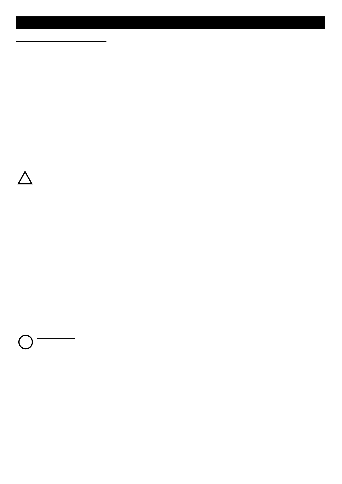
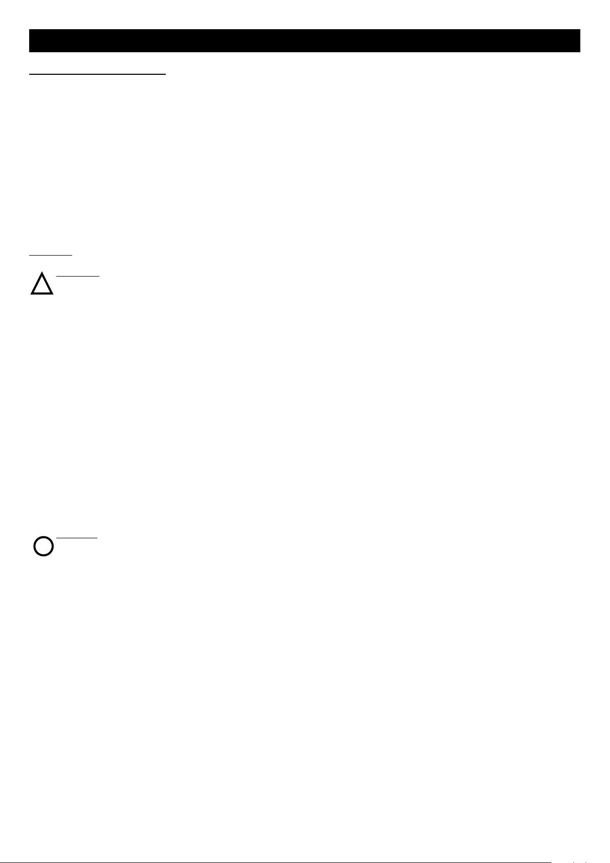
Significato delle bocchette passaggio aria (fig.2)
A: Mandata aria pulita in casa
B: Aspirazione aria viziata da casa
C: Aspirazione aria fresca dall’esterno
D: Mandata aria viziata verso l’esterno
4
Page 5
ITALIANO
3 3
4 4
5 5
1
2
Installazione
N.B. L’apparecchio non è adatto ad installazioni all’esterno.
L’apparecchio deve essere installato seguendo le norme di
sicurezza in vigore nel paese di destinazione, e le istruzioni
del presente libretto. L’apparecchio deve essere installato su
una superficie o parete interne all’abitazione e strutturalmente
adatte a reggerne il peso (max.25 Kg mod 200, max. 38 Kg
mod 350).
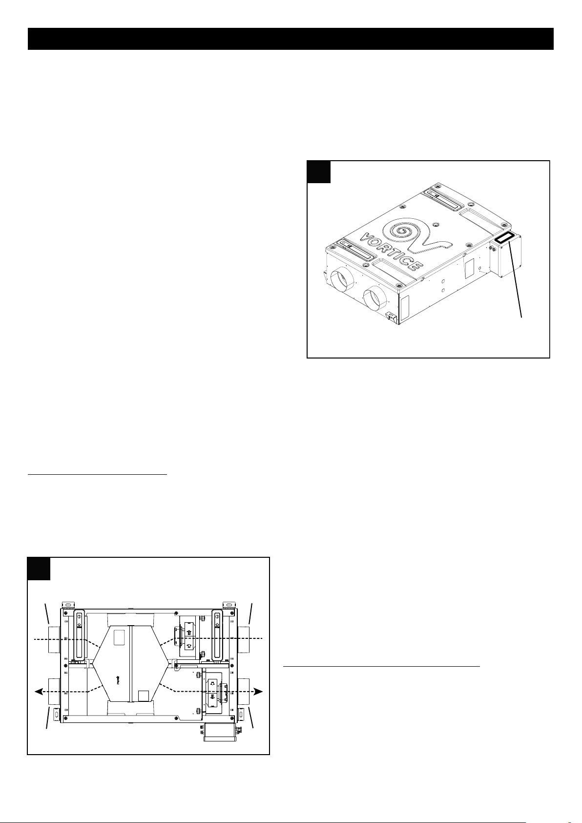
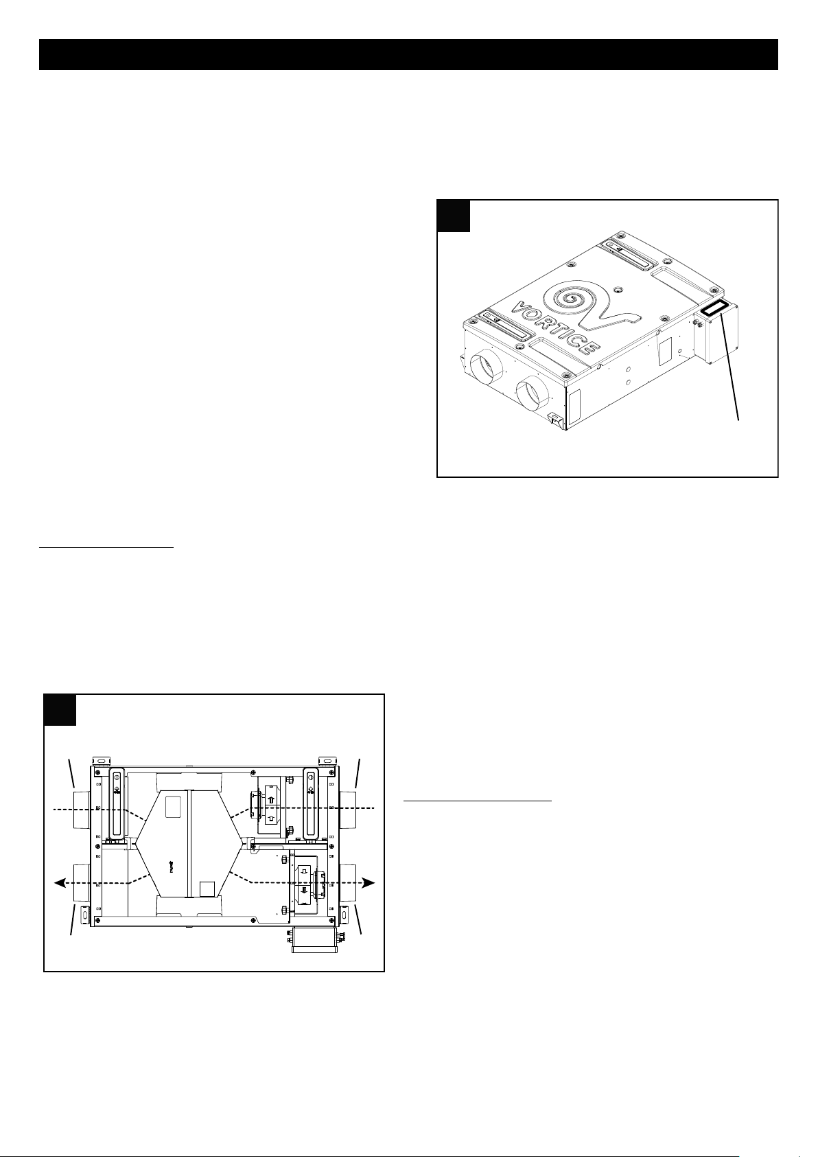
Al fine di ottimizzare e semplificare le connessioni
dell’apparecchio, tenere in considerazione la posizione
della scatola elettrica, da cui fuoriescono i cavi (fig.3).
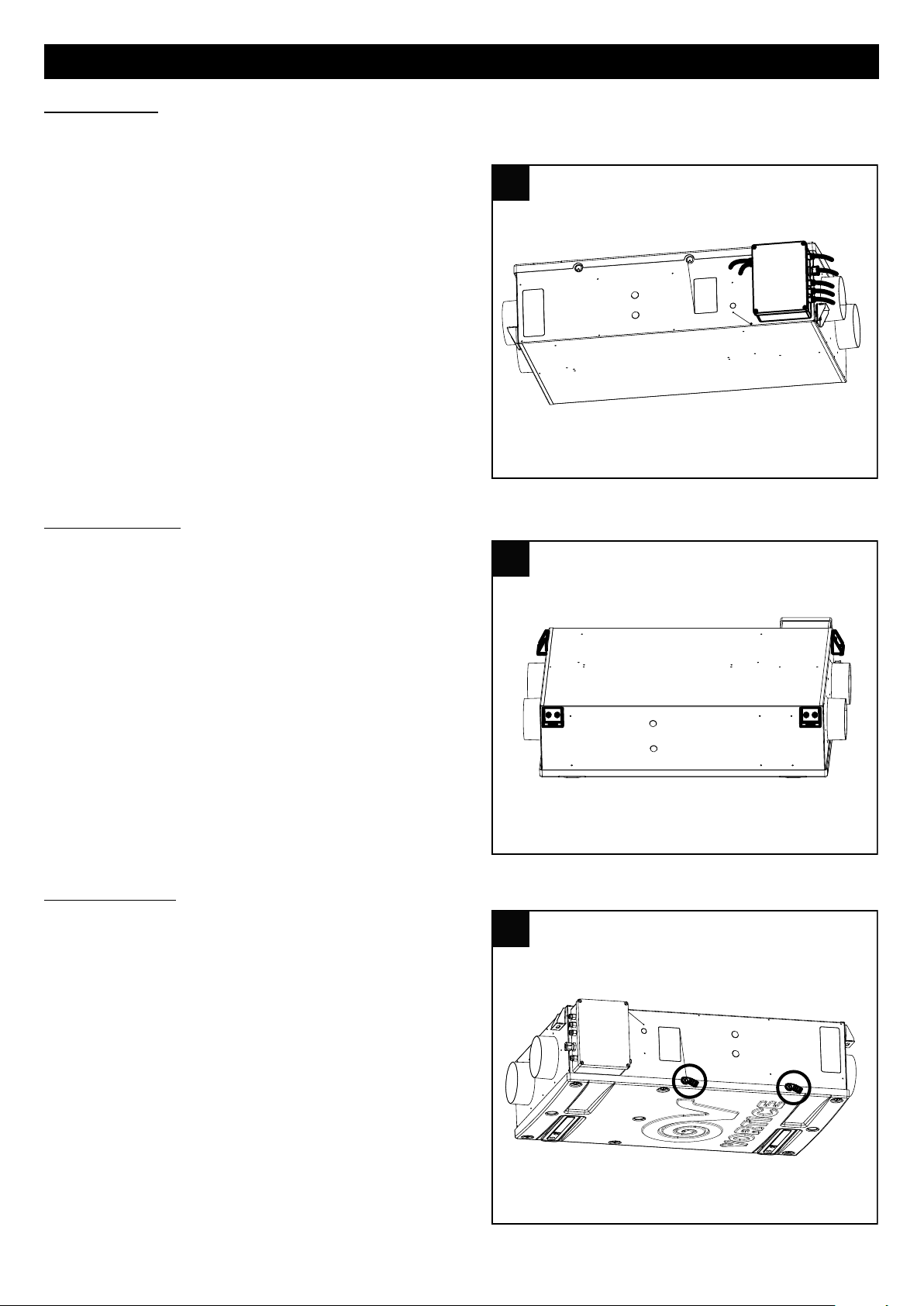
Montaggio a soffitto
Sono possibili diverse modalità di montaggio: Vortice
suggerisce di applicare l’apparecchio a soffitto utilizzando le
apposite staffe in dotazione (fig.4).
In ogni caso dopo il montaggio accertarsi che l’apparecchio
sia perfettamente in bolla, al fine di garantirne il perfetto
funzionamento. I condotti utilizzati per le canalizzazioni
devono essere delle corrette dimensioni.
I condotti da e verso l’esterno devono essere isolati
termicamente e non soggetti a vibrazioni.
Le tubazioni di aspirazione e mandata, di diametro nominale
pari a 125 mm (mod.200), 150 mm (mod. 350) devono essere
fissati allecorrispondenti bocche dell’apparecchio mediante
fascette o altri sistemi di tenuta adeguati.
Se lo scarico avviene dal tetto è obbligatorio l’utilizzo di un
opportuno dispositivo inteso ad evitare la formazione di
condensa e l’entrata di acqua piovana.
Se l’ingresso dell’aria avviene dal tetto è obbligatorio l’utilizzo
di un opportuno dispositivo inteso ad evitare la formazione di
condensa e l’entrata di acqua piovana.
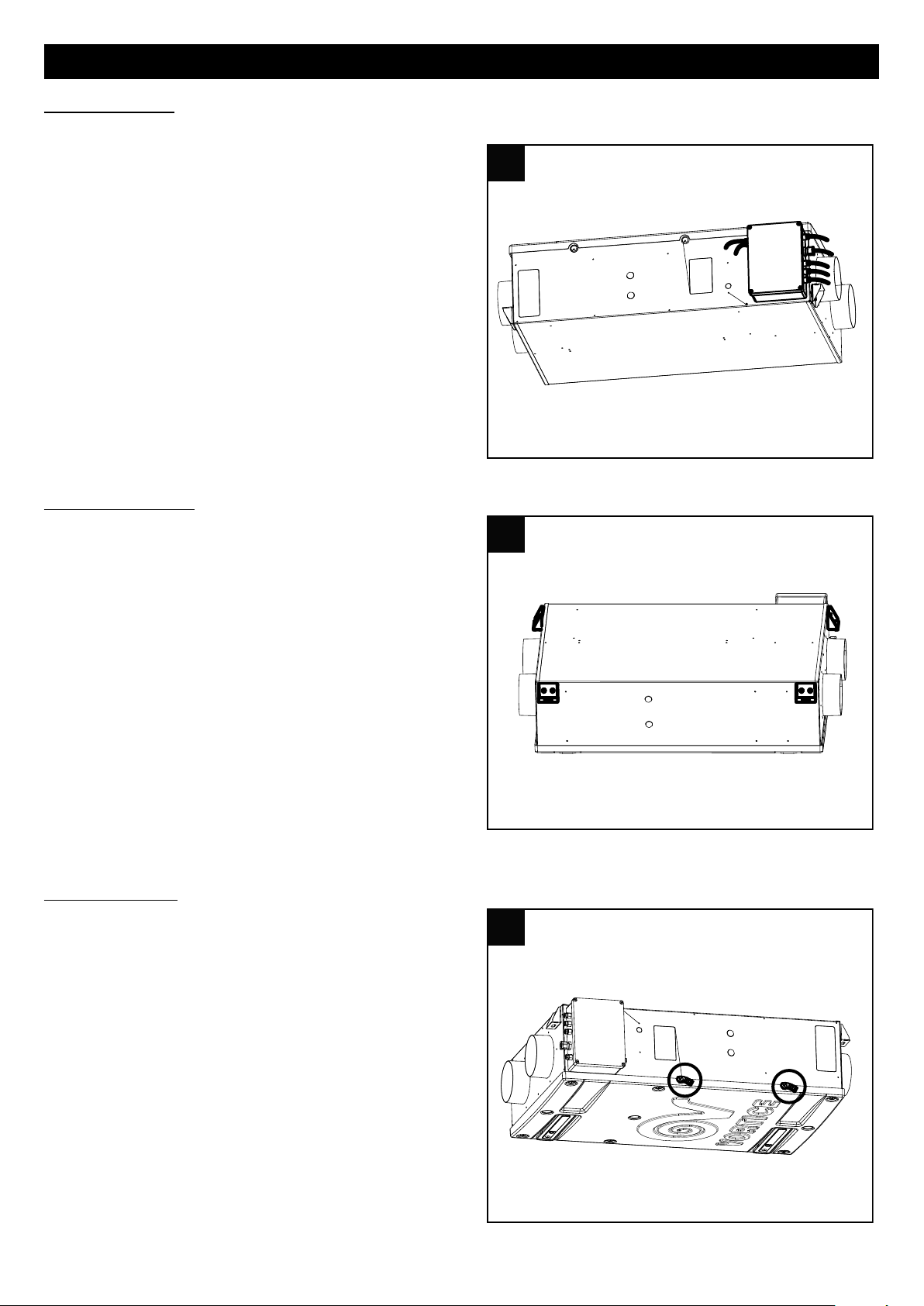
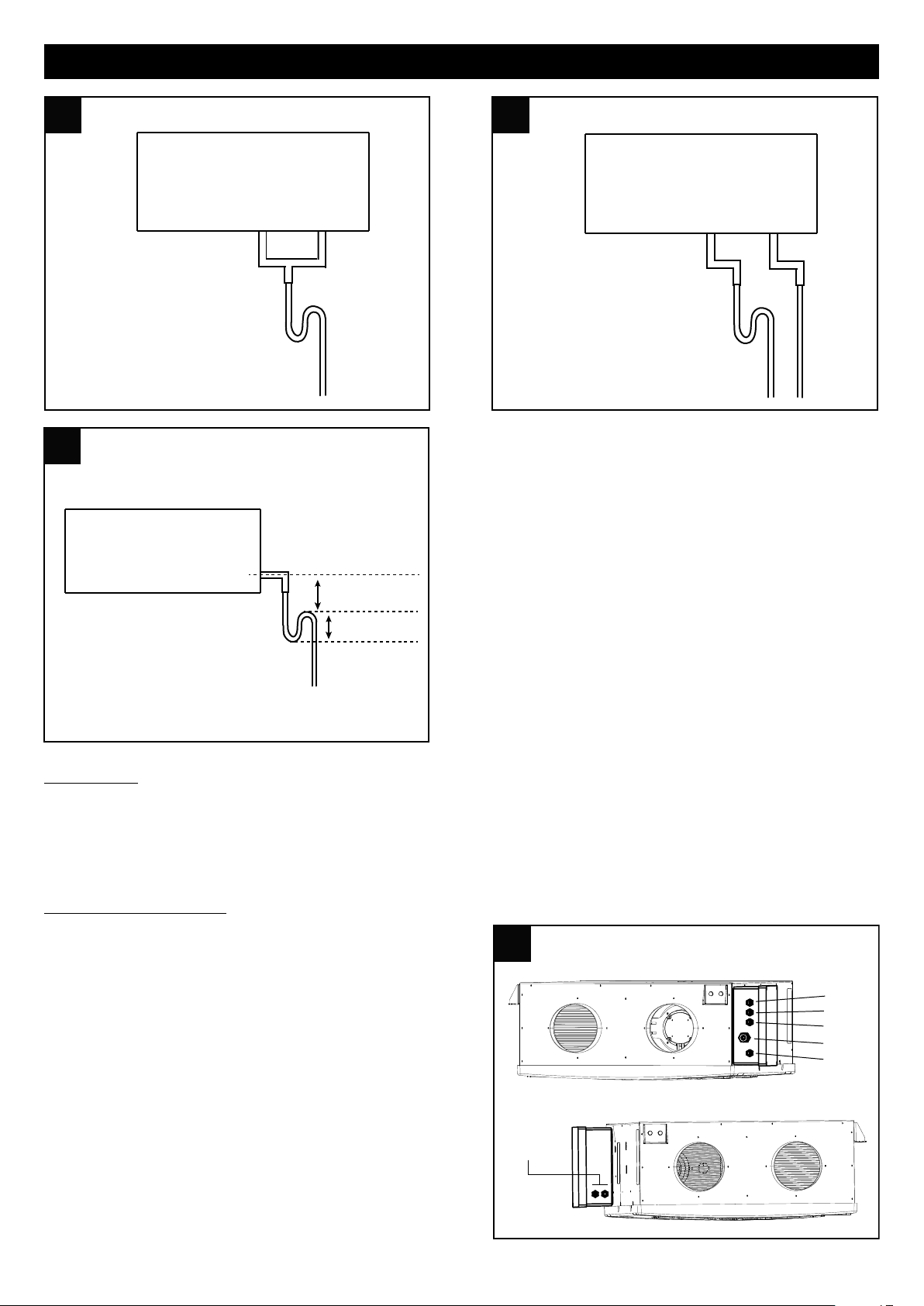
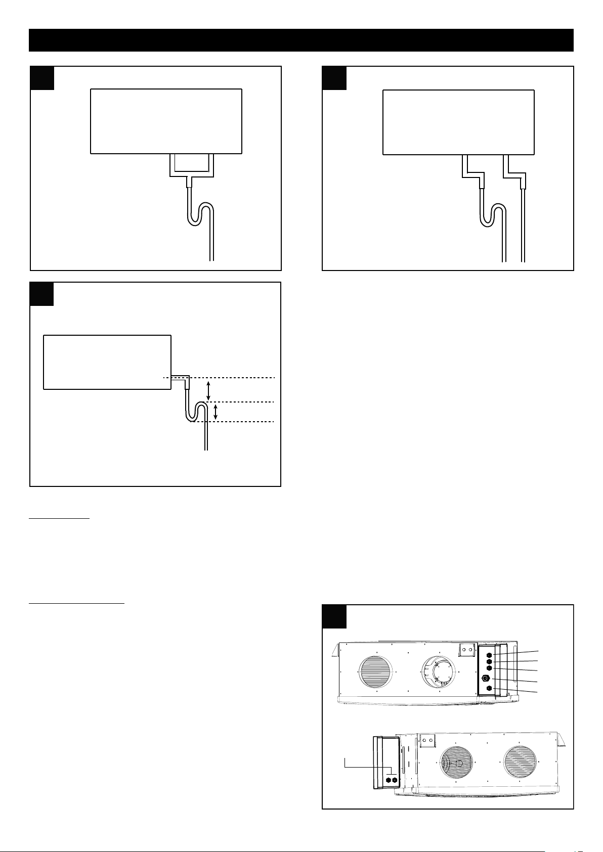
Scarico condensa
Nel corso del normale funzionamento, sul fondo
dell’apparecchio si raccoglie condensa, all’interno di una
doppia vaschetta che ha due scarichi verso l’esterno.
I punti di connessione sono posti sul fondo dell’apparecchio
(fig.5). Lo scarico della condensa può essere realizzato
connettendo agli scarichi due tubi flessibili, di diametro
interno pari a 19 mm circa.
Per impedire la formazione di bolle d’aria occorre realizzare
un sifone con il tubetto che fuoriesce dallo scarico
identificato col numero 1 sull’apparecchio, come indicato in
fig. 5b
Tagliare diagonalmente la terminazione del tubo.
N.B.
E’ necessario realizzare il sifone, rispettando le quote indicate
in fig. 5c; diversamente non è garantito il
regolare funzionamento dell’apparecchio.
Lo scarico della condensa può anche essere realizzato
sfruttando il sistema di fognatura della casa.
5
Page 6
ITALIANO
5a 5a
1
2
NO
5b 5b
OK
12
5c 5c
h > 50 mm∆
≥ 60 mm
6 6
B
A
1
2
3
4
5
6,7
Accessibilità
L’apparecchio deve essere facilmente accessibile nel caso di interventi di servizio/manutenzione. In particolare il
controsoffitto ospitante l’apparecchio deve prevedere una botola di ispezione di adeguate dimensioni, che renda possibile
agire sullo sportello di accesso alle parti elettriche/elettroniche e ai filtri. Non sarà quindi necessaria la disinstallazione
dell’apparecchio dal controsoffitto sia per le operazioni di manutenzione ordinaria (sostituzione filtri), che di alcune
operazioni straordinari (p.es. sostituzione di un motoventilatore o del controller elettronico).
Ingressi scatola elettrica
Fig 6A
1: Preheater: (per collegare il preheater occorre aprire il gruppo
elettronico, collegare i connettori grigi e configurare il software
(a cura dell’installatore).
2: Interruttori
4: Alimentazione
5: Display
Fig 6B
6,7: Termoattuatori bypass
6
Page 7
ITALIANO
7 7
ALIMENTAZIONE
GV - Y/G
L
N
marrone / brown
blu / blue
nero (GND)
blu (segnale)
marrone (+12V dc)
brown / +12V dc
blue / signal
black/ GND
SKP 10
black/ GND
blue / signal
brown / +12V dc
SKW 22
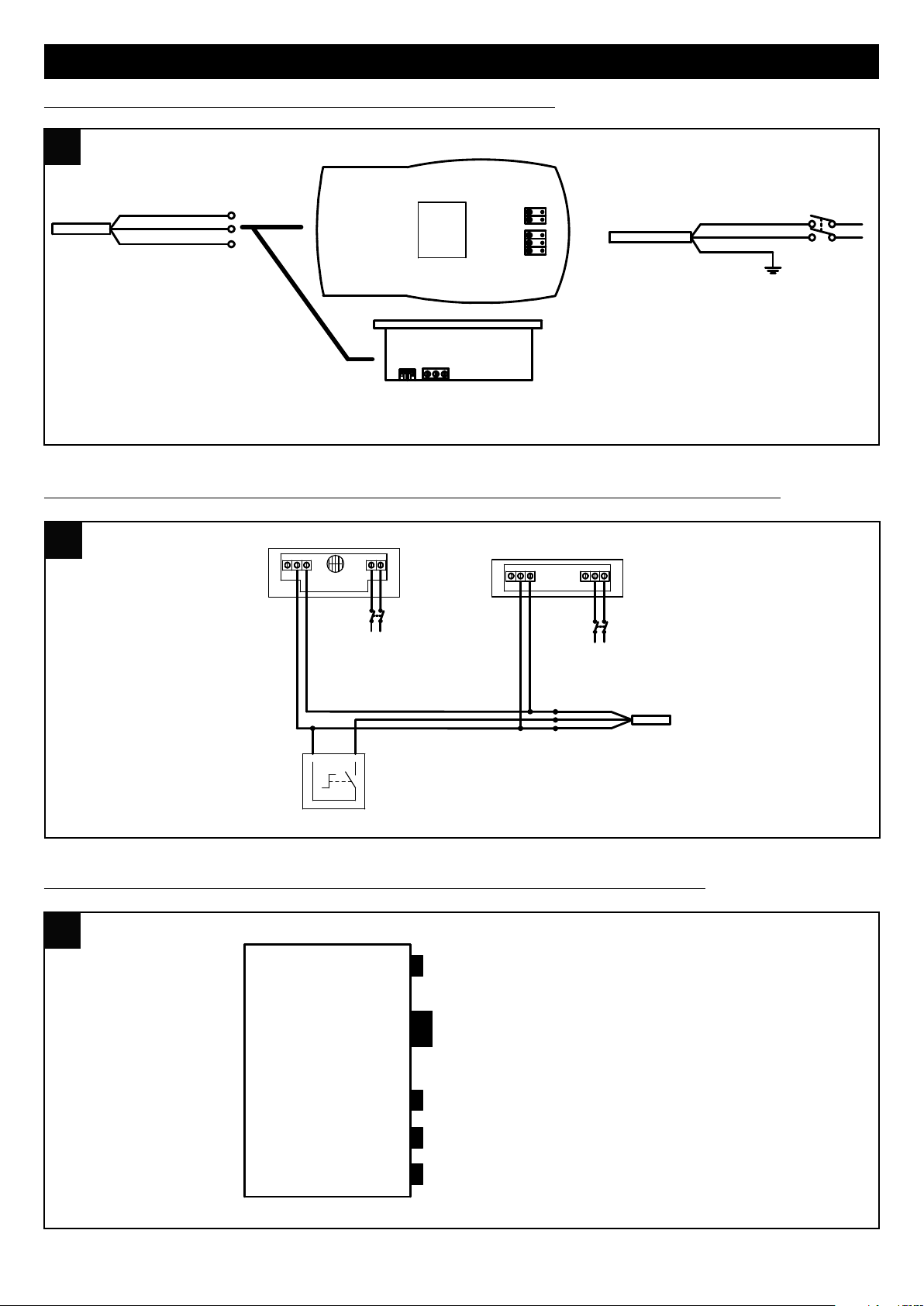
PANNELLO INSTALLATORE/UTENTE
8 8
2
3
0
V
5
0
H
z
L
N
N
L
1
2
3
S
e
n
s
o
r
e
C
S
M
O
K
E
/
C
T
E
M
P
3
2
1
T
m
N
L
2
3
0
V
5
0
H
z
N
L
S
e
n
s
o
r
e
C
P
I
R
/
C
H
C
S
marrone
2
1
S
e
l
e
t
t
o
r
e
O
N
-
O
F
F
r
e
m
o
t
o
verde
bianco
C
a
v
o
d
i
s
e
g
n
a
l
e
e
s
t
e
r
n
o
9 9
A
B
C
D
E
A = CAVO PANNELLO DI CONTROLLO
B = CAVO ALIMENTAZIONE
C = CAVO DISPOSITIVO ANTIBATTERICO (OPTIONAL)
D = CAVO SEGNALE ESTERNO
E = CAVO PRE HEATHER (OPTIONAL)
Collegamenti elettrici Vort HRI Phantom: Pannello Installatore/Utente
Collegamenti elettrici Vort HRI Phantom: Collegamento cavo segnale con sensori Vortice e ON-OFF
Collegamenti elettrici Vort HRI Phantom: Uscita cavi HRI PHANTOM da scatola cablaggio
7
Page 8
ITALIANO
esc set
10 10
B
y-Pass
/ °C
1234567
P1 P2
P1/P2
Prg
A
B
C
D
E
F
ILT
11 11
8 9 10 11 12 13
14
15
16 17 19
1 2 3 4 5 6 7
20
Utilizzo
Nei modelli B.P., all’accensione, dopo 2 minuti di funzionamento, l’apparecchio ferma entrambi i motori, per permettere il
riposizionamento della valvola di bypass. I motori si riattivano dopo circa 1 minuto.
N.B.: questo comportamento del sistema è normale e non deve essere considerato come anomalia.
Il controllo dell’apparecchio è realizzato tramite apposito pannello comandi dedicato, di cui nel seguito vengono descritte
le funzioni.
E’ possibile l’abbinamento di un pre-riscaldatore Vortice, la cui installazione è demandata all’installatore.
La distanza minima del pre-riscaldatore dall’apparecchio è di 500 mm.
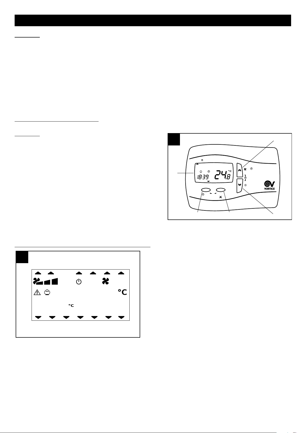
Funzioni pannello utente
Generalità (fig.10)
A = tasto “UP”: lista su
B = tasto “DOWN” : lista giù
C = tasto SET: acquisire dati
D = tasto ESC: uscire
E = display
L’utente dispone di un pannello con cui può gestire i parametri
di funzionamento dell’apparecchio:
- accensione/spegnimento
- ora/giorno corrente
- velocità di funzionamento
- temperatura ambiente richiesta
- forzatura funzione “bypass”
Il pulsante ESC, quando non diversamente specificato, ha sempre la funzione di uscire senza salvare dati.
Quadro riassuntivo delle icone presenti sul pannello (fig.11)
1÷7giorno della settimana: 1=lunedì, 2=martedì, ecc.
8 allarme filtri: l’accensione dell’icona indica che entro due
mesi è necessario sostituire i filtri; se la sostituzione non
avviene entro tale periodo il sistema segnala l’errore filtri Filt
(vedi paragrafo “Visualizzazione menu allarmi”)
9 funzione no-frost: l’accensione dell’icona fissa indica che è
attiva la procedura di no-frost; l’icona lampeggiante indica
una condizione di “no-frost timeout”: la procedura di nofrost in questo caso non è sufficiente e l’apparecchio entra
in protezione per un’ora, a motori fermi, dopo di che il
sistema riattiva la macchina.
10 profilo orario P1: (vedi paragrafo “Menu Utente”)
11 profilo orario P2: (vedi paragrafo “Menu Utente”)
12 HA
13 -14 velocità attuale di funzionamento: l’accensione delle icone fisse indica a quale delle 3 velocità sta funzionando
l’apparecchio.
15 stato di stand-by del sistema: l’accensione dell’icona fissa indica che l’apparecchio è in stand-by (acceso ma con i
motori spenti); l’icona lampeggiante indica che l’apparecchio è in stand by a seguito della programmazione delle
fasce orarie (vedi paragrafo “Programmazione dei profili orari”); se oltre all’icona appare la scritta “OFF” sulla parte
destra del display l’apparecchio risulta spento da remoto, in un eventuale sistema domotico.
16 l’accensione dell’icona lampeggiante indica la presenza di un allarme; l’icona fissa rappresenta un allarme non
8
resettabile manualmente (vedi paragrafo “Visualizzazione menu allarmi”)
Page 9
ITALIANO
esc set
By-Pass
/ ° C
1234567
FILT
P1 P2
Prg
12 12
HA
esc set
By-Pass
/ ° C
1234567
FILT
P1 P2
Prg
13 13
HA
esc set
By-Pass
/ ° C
1234567
FILT
P1 P2
Prg
14 14
HA
17 funzione bypass: l’icona indica: (vedi anche paragrafo “Attivazione funzione Bypass”)
spenta: bypass disattivato
accesa fissa: bypass aperto tramite comando manuale
lampeggiante: bypass aperto automaticamente via software (in questo caso non è possibile chiudere il
bypass manualmente)
18 visualizzazione ora
18 gradi Celsius temperatura interna
19 visualizzazione temperatura esterna gradi Celsius
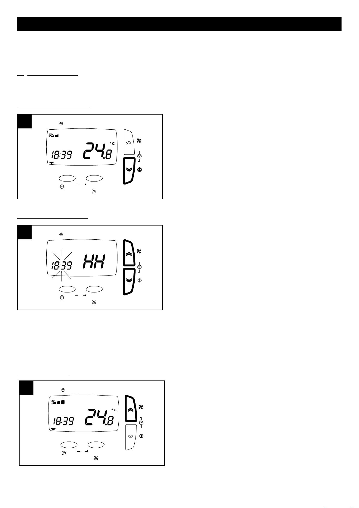
Accensione/spegnimento (fig.12)
L’apparecchio si accende/spegne tramite una pressione lunga
sul tasto “down” del pannello.
Impostazione ora/giorno (fig.13)
Selezione velocità (fig.14).
Prima di eseguire i passi indicati nel seguito premere il tasto
ESC per uscire e posizionarsi sul menu iniziale.
L’ora e il giorno corrente possono essere impostati nel modo
seguente:
- pressione breve simultanea dei pulsanti “up” e “down”
- pressione breve pulsanti “up” e “down”, per regolazione
parametro “ora” (HH);
- pressione breve pulsante SET per acquisizione dato “ora” e
passaggio a parametro “minuti” (MM);
- pressione breve pulsanti “up” e “down”, per regolazione
parametro “minuti” ;
- pressione breve pulsante SET per acquisizione dato “minuti”
e passaggio a parametro “giorno” (dAy);
- pressione breve pulsanti “up” e “down”, per regolazione
parametro “giorno”;
- pressione breve pulsante SET per acquisizione dato “giorno”
e uscita.
Prima di eseguire i passi indicati nel seguito premere il tasto
ESC per uscire e posizionarsi sul menu iniziale.
La velocità di funzionamento, preimpostata in fase di
configurazione, può essere selezionata con una pressione
breve sul tasto “up” (1=Vel min, 2=Vel med, 3=Vel max).
9
Page 10
ITALIANO
esc set
By-Pass
/
°C
1234567
F
ILT
P
1P2
P1/P2
Prg
15 15
esc set
By-Pass
/
°C
1234567
FILT
P1 P2
P1/P2
Prg
16 16
esc set
By-Pass
/ ° C
1234567
FILT
P1 P2
Prg
17 17
HA
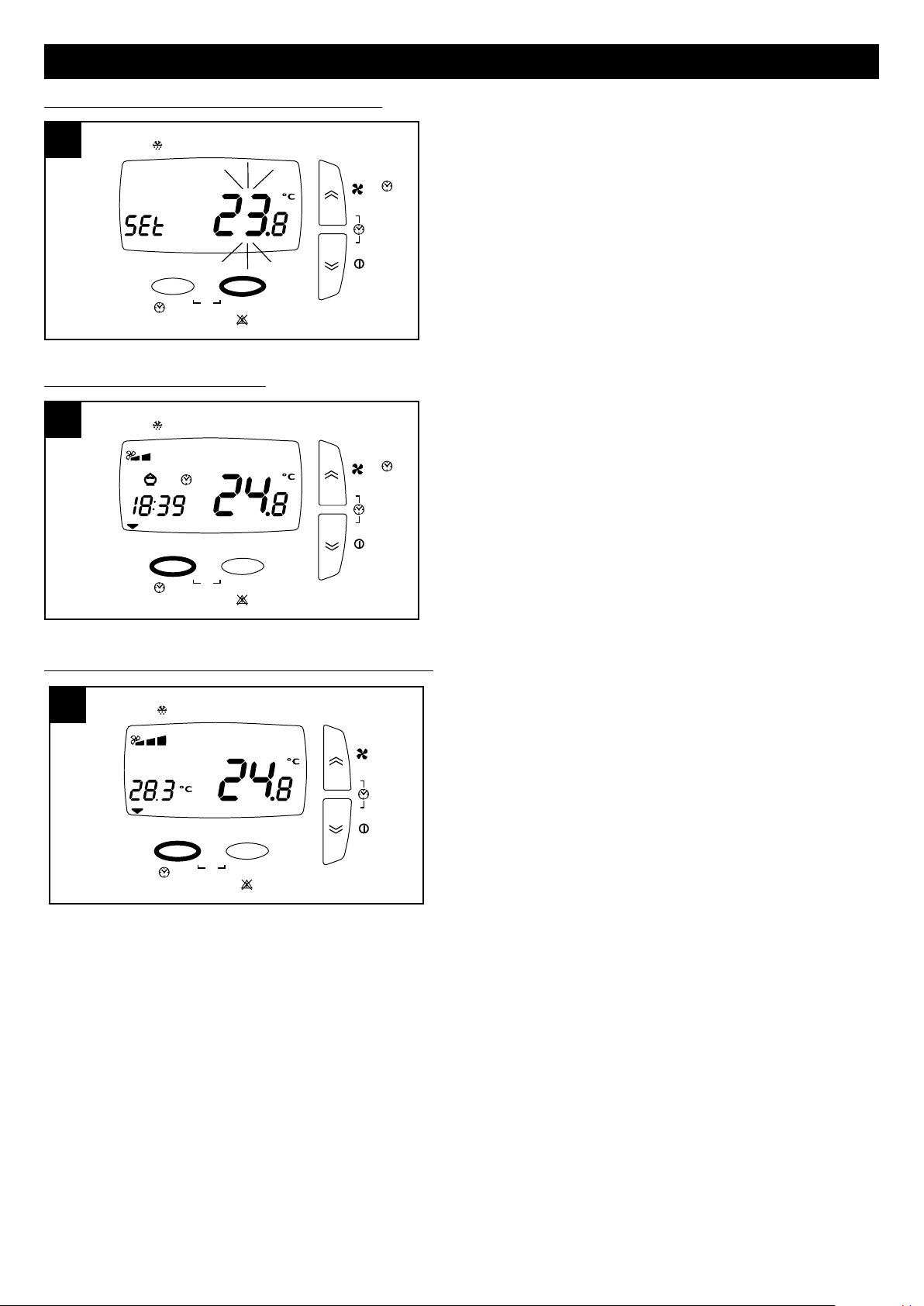
Impostazione temperatura ambiente richiesta (fig.15).
Attivazione funzione “bypass” (fig.16)
Prima di eseguire i passi indicati nel seguito premere il tasto
ESC per uscire e posizionarsi sul menu iniziale.
La temperatura ambiente desiderata può essere selezionata nel
seguente modo:
- pressione lunga del pulsante SET
- pressione breve del pulsante SET (il valore corrente
lampeggia)
- selezione del valore desiderato tramite pulsanti “up” e “down”
- pressione breve del pulsante SET per acquisire il dato
- pressione breve del pulsante ESC per uscire
Lo scopo della funzione bypass è ventilare l’appartamento
senza trasferimenti di calore. L’apertura della valvola di by-pass
consente l’immissione diretta dell’aria esterna, evitandone il
passaggio all’interno dello scambiatore di calore. Il flusso d’aria
espulsa dalla casa continua invece a transitare attraverso lo
scambiatore.
Prima di eseguire i passi indicati nel seguito premere il tasto
ESC per uscire e posizionarsi sul menu iniziale.
La funzione “bypass” può essere forzata tramite pressione lunga
del pulsante ESC. Si accenderà l’icona corrispondente
“salvadanaio”.
Attivazione visualizzazione ora/temperatura esterna (fig.17)
Prima di eseguire i passi indicati nel seguito premere il tasto
ESC per uscire e posizionarsi sul menu iniziale.
I valori attuali dei parametri “ora” e “temperatura esterna”
possono essere visualizzati alternativamente tramite pressione
breve del pulsante ESC.
10
Page 11
esc set
By-Pass
/
°C
1234567
FILT
P2
Prg
18 18
P1
HA
ITALIANO
esc set
By-Pass
/ ° C
1234567
FILT
P2
Prg
19 19
P1
HA
Menu utente
Prima di eseguire i passi indicati nel seguito premere il tasto
ESC per uscire e posizionarsi sulla schermata iniziale.
In generale i parametri relativi alle varie opzioni sono impostabili
premendo SET (il valore corrente inizia a lampeggiare),
selezionando i diversi valori tramite i pulsanti UP e DOWN e
premendo nuovamente SET per acquisire il nuovo valore. Anche
lo scorrimento tra le diverse opzioni o parametri avviene tramite
i pulsanti UP e DOWN.
Il menu generale utente può essere visualizzato tramite la
pressione simultanea dei pulsanti ESC e SET. Le opzioni del
menu sono:
- PROF: impostazioni funzionamento con profili orari:
P1 permette di programmare un intervallo di funzionamento al giorno, con un orario di inizio, un orario di fine e una
velocità;
P2 permette di programmare due intervalli di funzionamento al giorno, ognuno con un orario di inizio , un orario di fine
e una velocità.
E’ possibile assegnare un profilo diverso ad ogni giorno della settimana.
- HA: impostazioni funzionamento HA: presente solo su apparecchi dotati di modulo HA, e solo se non è abilitato il
funzionamento del sistema principale con profili orari.
- SERV: servizio (opzione riservata all’installatore)
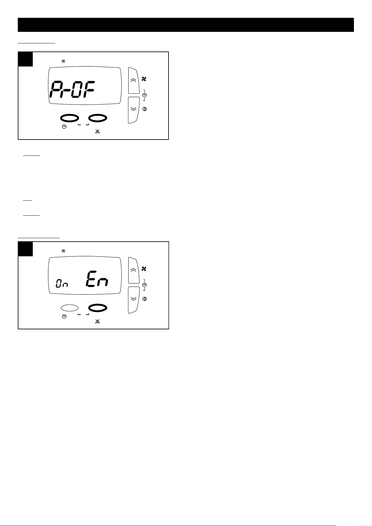
Opzione PROF
Selezionando PROF tramite pulsante SET si entra nelle
impostazioni dei profili orari. I parametri sono:
- En (Enable): i valori possibili sono:
ON: abilita il funzionamento con profili (e come detto sopra
viene automaticamente disabilitato l’eventuale funzionamento
in modalità HA)
OFF: disabilita il funzionamento con profili.
Se è stato selezionato EN ON vengono abilitati anche i seguenti
parametri:
- ST: orario inizio intervallo di profilo P1
- END: orario fine intervallo di profilo P1
- SP: velocità profilo P1: i valori possibili sono 1, 2, 3
- ST1 : orario inizio intervallo 1 di profilo P2
- EN1 : orario fine intervallo 1 di profilo P2
- SP1: velocità intervallo 1 di profilo P2: i valori possibili sono 1, 2, 3
- ST2 : orario inizio intervallo 2 di profilo P2
- EN2 : orario fine intervallo 2 di profilo P2
- SP2: velocità intervallo 2 di profilo P2: i valori possibili sono 1, 2, 3
- MON: assegnazione profilo al giorno lunedi: i valori possibili sono P1 e P2
- TUE: assegnazione profilo al giorno martedi: i valori possibili sono P1 e P2
- UED: assegnazione profilo al giorno mercoledi: i valori possibili sono P1 e P2
- THR: assegnazione profilo al giorno giovedi: i valori possibili sono P1 e P2
- FRY: assegnazione profilo al giorno venerdi: i valori possibili sono P1 e P2
- SAT: assegnazione profilo al giorno sabato: i valori possibili sono P1 e P2
- SUN: assegnazione profilo al giorno domenica: i valori possibili sono P1 e P2
11
Page 12
ITALIANO
esc set
By-Pass
/ ° C
1234567
FILT
P1 P2
P1/P2
Prg
21 21
esc set
By-Pass
/ ° C
1234567
FILT
P
2
Prg
20 20
P
1
HA
Opzione HA
L’opzione è disponibile solo per i modelli dotati di modulo HA e
se non è abilitato il funzionamento del sistema principale con
profili orari.
Selezionando HA tramite pulsante SET si entra nelle
impostazioni della modalità HA. I parametri sono:
- En (Enable): i valori possibili sono:
PROF: abilita la modalità HA con profili
ON: abilita la modalità HA continua
OFF: disabilita la modalità HA
HOL: abilità la modalità HOLIDAY: due ore di funzionamento
antibatterico al giorno, due ore di rinnovo aria, 20 ore di
stand-by.
Se è stato selezionato EN PROF vengono abilitati anche i
seguenti parametri:
- ST: orario inizio intervallo di profilo P1
- END: orario fine intervallo di profilo P1
- ST1 : orario inizio intervallo 1 di profilo P2
- EN1 : orario fine intervallo 1 di profilo P2
- ST1 : orario inizio intervallo 2 di profilo P2
- EN1 : orario fine intervallo 2 di profilo P2
- MON: assegnazione profilo al giorno lunedi: i valori possibili sono P1 e P2
- TUE: assegnazione profilo al giorno martedi: i valori possibili sono P1 e P2
- UED: assegnazione profilo al giorno mercoledi: i valori possibili sono P1 e P2
- THR: assegnazione profilo al giorno giovedi: i valori possibili sono P1 e P2
- FRY: assegnazione profilo al giorno venerdi: i valori possibili sono P1 e P2
- SAT: assegnazione profilo al giorno sabato: i valori possibili sono P1 e P2
- SUN: assegnazione profilo al giorno domenica: i valori possibili sono P1 e P2
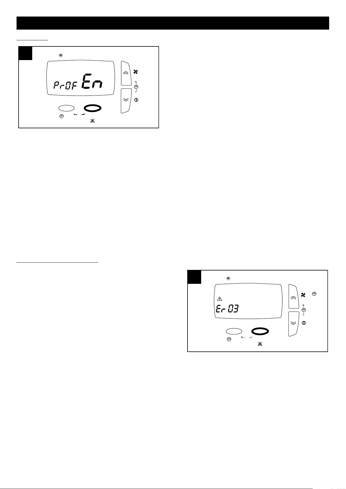
Visualizzazione menu allarmi (fig.21)
Prima di eseguire i passi indicati nel seguito premere il tasto
ESC per uscire e posizionarsi sul menu iniziale.
Le segnalazioni d’allarme eventualmente presenti possono
essere visualizzate nel seguente modo:
--pressione lunga del pulsante SET
--pressione breve su UP o DOWN in modo da visualizzare il
menu ALRM
--pressione breve del pulsante SET per visualizzare il codice
d’errore attivo
Il sistema può presentare diverse situazioni d’allarme,
evidenziate come segue sul pannello utente:
ti: sensore temperatura interna guasto; richiedere l’intervento
dell’ Assistenza Tecnica;
tout: sensore temperatura esterna guasto; richiedere l’intervento dell’ Assistenza Tecnica;
te: sensore temperatura aria di scarico guasto; richiedere l’intervento dell’ Assistenza Tecnica;
preh: pre-heater guasto, o non presente (se previsto); richiedere l’intervento dell’ Assistenza Tecnica;
Hito: temperatura esterna superiore a 45° C; richiedere l’intervento dell’ Assistenza Tecnica;
Hiti: temperatura interna superiore a 45° C; richiedere l’intervento dell’ Assistenza Tecnica;
Filt: è necessario sostituire i filtri saturi (2 mesi). Dopo la sostituzione dei filtri l’errore è resettabile dall’utente: a tale scopo
è sufficiente una pressione lunga simultanea dei tasti UP e DOWN.
N.B. Il reset degli errori a riarmo manuale è possibile tramite pressione lunga del tasto UP e DOWN.
12
Page 13
ITALIANO
22 22
Manutenzione / pulizia
Prima di iniziare qualsiasi operazione accertarsi che il prodotto sia scollegato dalla rete elettrica. Lo smontaggio e relativo
montaggio sono operazioni di manutenzione straordinaria e devono essere eseguite da personale professionalmente
qualificato.
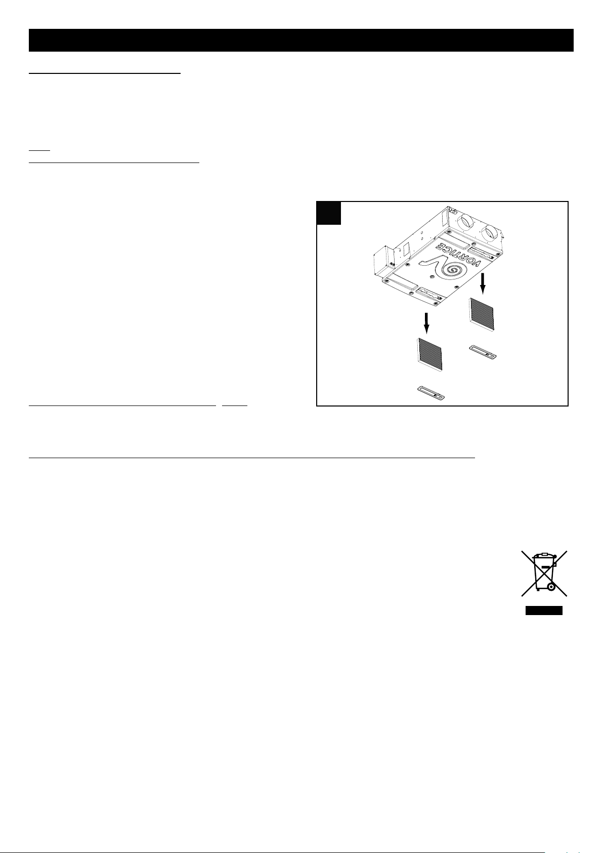
Filtri
Tempi consigliati per la manutenzione:
in generale in funzione dell’area geografica di installazione il livello di inquinamento dell’aria è variabile, e quindi è variabile
la durata dei filtri. Tenendo presenti queste considerazioni i tempi per la manutenzione dei filtri sono i seguenti:
Ispezione filtri: ogni 50/60 giorni;
sostituzione filtri: dopo 3/24 mesi (in base a quanto
impostato in fase di installazione dall’installatore) appare sul
display un messaggio di preallarme che avvisa l’utente che è
necessario sostituire i filtri. Da questo momento i filtri devono
essere sostituiti entro 2 mesi; allo scadere dei 2 mesi si attiva
l’allarme di filtri saturi (Filt). Con il reset dell’errore (descritto
nel paragrafo “Visualizzazione menu allarmi”) viene resettato
anche il contatore.
N.B. La mancata pulizia o sostituzione dei filtri comporta
gravi inconvenienti per l’efficienza dell’impianto, con:
- aumento delle perdite di carico nel circuito aria e riduzione
di portata aria;
- conseguente diminuzione della resa della macchina e
peggioramento del confort in ambiente.
N.B. La situazione di filtri saturi rappresenta la causa più
frequente di blocco dell’apparecchio: (Filt)
Estrazione filtri modelli Vort HRI Phantom: fig 22
Informazione importante per lo smaltimento ambientalmente compatibile
IN ALCUNI PAESI DELL'UNIONE EUROPEA QUESTO PRODOTTO NON RICADE NEL CAMPO DI APPLICAZIONE
DELLA LEGGE NAZIONALE DI RECEPIMENTO DELLA DIRETTIVA RAEE E QUINDI NON È IN ESSI VIGENTE
ALCUN OBBLIGO DI RACCOLTA DIFFERENZIATA A FINE VITA.
Questo prodotto è conforme alla Direttiva EU2002/96/EC.
Il simbolo del bidone barrato riportato sull’apparecchio indica che il prodotto, alla fine della propria vita
utile, dovendo essere trattato separatamente dai rifiuti domestici, deve essere conferito in un centro di
raccolta differenziata per apparecchiature elettriche ed elettroniche oppure riconsegnato al rivenditore al
momento dell’acquisto di una nuova apparecchiatura equivalente.
L’utente è responsabile del conferimento dell’apparecchio a fine vita alle appropriate strutture di raccolta,
pena le sanzioni previste dalla vigente legislazione sui rifiuti.
L’adeguata raccolta differenziata per l’avvio successivo dell’apparecchio dismesso al riciclaggio, al trattamento e allo
smaltimento ambientalmente compatibile contribuisce ad evitare possibili effetti negativi sull’ambiente e sulla salute e
favorisce il riciclo dei materiali di cui è composto il prodotto.
Per informazioni più dettagliate inerenti i sistemi di raccolta disponibili, rivolgersi al servizio locale di smaltimento rifiuti o
al negozio in cui è stato effettuato l’acquisto.
I produttori e gli importatori ottemperano alla loro responsabilità per il riciclaggio, il trattamento e lo smaltimento
ambientalmente compatibile sia direttamente sia partecipando ad un sistema collettivo.
13
Page 14
ENGLISH
Description and use
Vort HRI Phantom (hereinafter "the appliance") is a highly energy-efficient central ventilation system with heat recovery,
which can be installed horizontally in a false ceiling. The appliance is controlled by a hi-tech electronic management
system and equipped with fan units that utilise energy-saving EC brushless motors.
A heat exchanger is fitted inside the appliance to guarantee heat exchange efficiency levels of up to 94%.
The appliance is available in 4 models offering different performance features:
Vort HRI Phantom (200 and 350): basic version
Vort HRI Phantom B.P. (200 and 350): version equipped with additional Bypass function.
(See “Use” for a more detailed description of the various functions).
These appliances have been designed for domestic and commercial use.
Safety
Warning:
this symbol indicates that care must
!
be taken to avoid injury to the user
• Follow the safety instructions to prevent any harm to the user.
• Do not use this appliance for purposes other than those described in this manual.
• Having removed the appliance from its packaging, make sure that it is intact and undamaged. If in doubt, consult a
professional or contact a Vortice Authorised Technical Support Centre.
• Do not leave packaging within reach of children or individuals with disabilities.
• Certain fundamental rules must be observed when using any electrical appliance:
never touch the appliance with wet or damp hands;
never touch the appliance while barefoot.
• Do not operate the appliance in the presence of flammable substances or vapours, such as alcohol, insecticides, petrol,
etc.
• If the appliance is to be disconnected from the power supply and no longer used, store it out of reach of children and
individuals with disabilities.
• This appliance can be used by children aged from 8 years and above and persons with reduced
physical, sensory or mental capabilities or lack of experience and knowledge if they have been given
supervision or instruction concerning use of the appliance in a safe way and understand the hazards
involved. Children shall not play with the appliance. Cleaning and user maintenance shall not be
made by children without supervision.
Caution:
this symbol indicates that care must
!
be taken to avoid damaging the appliance
• Do not make modifications of any kind to this appliance.
• The maintenance instructions must be followed to ensure the appliance does not suffer damage and/or excessive wear.
• Do not expose this appliance to the elements (rain, sun, etc.).
• Do not stand objects on the appliance.
• The inside of the appliance must be cleaned only by a skilled professional.
• Regularly inspect the appliance for visible defects. If the appliance is defective in any way, do not use it, and contact a
Vortice authorised Technical Support Centre without delay.
• If the appliance does not function correctly or develops a fault, contact a Vortice authorised Technical Support Centre
without delay. Ensure that only genuine original Vortice spares are used for any repairs.
• If the power supply cable is damaged, have it replaced without delay by a Vortice authorised Technical Support Centre.
• Should the appliance be dropped or suffer heavy impact, have it checked without delay by a Vortice authorised Technical
Support Centre.
• The appliance must be installed in such a way as to ensure that under normal operating conditions, no one can come
into contact with any moving parts or live electrical components.
• Should you need to:
dismantle the appliance, using the proper tools;
remove the heat exchanger;
remove the motor module;
the appliance must first be switched off and disconnected from the electrical power supply.
• The electrical system to which the appliance is connected must conform to applicable standards.
14
Page 15
ENGLISH
2 2
A
B
C
D
1 1
AA
• Connect the appliance to the electrical power supply/socket only if the rated power of the supply is compatible with the
maximum rated power of the appliance. If not, contact a professional electrician without delay.
• Switch off the system's main switch:
if an operating fault is detected;
before cleaning the outside of the appliance;
if the appliance is not going to be used for any length of time.
• The appliance cannot be used to pilot the operation of water
heaters, stoves, etc.; neither must it drain into the hot water
ducts of such appliances.
• The appliance must expel air directly to the outside through a
single dedicated duct.
• The flow of extracted air must be clean (i.e. free of grease,
soot, chemical and corrosive agents and explosive or
flammable mixtures).
• Keep the air intake and outlet ports of the appliance free of
obstructions, to ensure optimum air flow.
• Maximum operating temperature: 45°C.
• Specifications for the power supply must correspond to the
electrical data on ID plate A (Fig. 1).
• The appliance must be installed by a
professionally qualified electrician.
• A multi-pole switch must be used to install the
appliance. The contact opening gap must be no
less than 3 mm.
Items supplied
The main parts of the appliance are:
• an outer casing made using galvanised steel;
• a polystyrene counterflow type heat exchanger, featuring a special geometry designed to guarantee the highest possible
efficiency in terms of heat exchange (up to 94%);
• two energy-saving variable-speed brushless motors (3 preset speeds);
• an electronic controller supervising the power input, regulation and control of the appliance;
• two thermal actuators controlling bypass valve opening (where applicable);
• remote control panel;
• 3 temperature sensors;
• 2 x F5 filters;
• 4 brackets for ceiling application.
Key to air connections (fig.2)
A: Clean air outlet inside the room
B: Stale air intake from room
C: Fresh air intake from outside
D: Stale air outlet to outside
15
Page 16
ENGLISH
3 3
4 4
5 5
1
2
Installation
N.B.
The appliance is not suitable for outdoor installation.
The appliance must be installed in accordance with current
safety regulations in the destination country, and with the
instructions in this booklet. The appliance must be fitted to an
interior surface or wall of the dwelling that is structurally sound
enough to take its weight (25 kg max. mod. 200, 38 kg max.
mod. 350).
Ensure that connections to the appliance are optimised and
simplified by strategic positioning of the junction box, from
which the wires emerge (Fig.3).
Ceiling installation
Various mounting options are available: Vortice recommends
fixing the appliance to the ceiling, using the special brackets
supplied (Fig.4).
In any event, after mounting the appliance, check that it is
perfectly level in order to ensure faultless operation. The ducts
used for conveying air must be of the correct size.
The ducts to and from the outdoors must be thermally
insulated and not subject to vibration.
The 125 mm (mod. 200) and 150 mm (mod. 350) standard
diameter inlet and outlet pipes must be secured to the
corresponding ports of the appliance by means of clips or
other suitable fastening systems.
If stale air is exhausted via the roof, the outlet must be
designed so as to prevent the formation of condensate and
the entry of rain water.
If fresh air enters via the roof, the intake must be designed so
as to prevent the formation of condensate and the entry of rain
water.
Condensate drain
During normal operation, condensate collects at the bottom of
the appliance in a double tray provided with two drain outlets.
The connection points are located on the bottom of the
appliance (Fig. 5). The condensate drain can be provided by
connecting the drain outlets to two flexible hoses with an
internal diameter of 19 mm approx.
To avoid the formation of air bubbles, create a siphon trap in
the hose connected to the outlet on the appliance denoted 1,
as illustrated in Fig. 5b.
Cut the end of the hose obliquely.
N.B.
The siphon must be created observing the dimensions
indicated in Fig. 5c; otherwise, correct operation of the
appliance cannot be guaranteed.
Condensate can also be drained off through the waste
plumbing system of the building.
16
Page 17
ENGLISH
5a 5a
1
2
NO
5b 5b
OK
12
5c 5c
h > 50 mm∆
≥ 60 mm
6 6
B
A
1
2
3
4
5
6,7
Accessibility
The appliance must be easily accessible for servicing/maintenance purposes. In particular, the false ceiling in which the
appliance is installed must have a suitably proportioned inspection hatch, providing access to the flap enclosing the
electrical/electronic parts and the filters. This means the appliance does not have to be removed from the false ceiling
during routine maintenance (filter replacement), nor even some non-routine procedures (e.g. motorised fan or electronic
controller replacement).
Junction box inputs
Fig 6A
1: Preheater (to connect the preheater, open the electronic
unit, plug in the grey connectors and configure the software
(installer access only)
2: Switches
4: Power Supply
5: Display
Fig. 6B
6.7: Thermal actuators bypass
17
Page 18
7 7
ALIMENTAZIONE
GV - Y/G
L
N
marrone / brown
blu / blue
nero (GND)
blu (segnale)
marrone (+12V dc)
brown / +12V dc
blue / signal
black/ GND
SKP 10
black/ GND
blue / signal
brown / +12V dc
SKW 22
PANNELLO INSTALLATORE/UTENTE
8 8
2
3
0
V
5
0
H
z
L
N
N
L
1
2
3
S
e
n
s
o
r
e
C
S
M
O
K
E
/
C
T
E
M
P
3
2
1
T
m
N
L
2
3
0
V
5
0
H
z
N
L
S
e
n
s
o
r
e
C
P
I
R
/
C
H
C
S
marrone
2
1
S
e
l
e
t
t
o
r
e
O
N
-
O
F
F
r
e
m
o
t
o
verde
bianco
C
a
v
o
d
i
s
e
g
n
a
l
e
e
s
t
e
r
n
o
9 9
A
B
C
D
E
A = CAVO PANNELLO DI CONTROLLO
B = CAVO ALIMENTAZIONE
C = CAVO DISPOSITIVO ANTIBATTERICO (OPTIONAL)
D = CAVO SEGNALE ESTERNO
E = CAVO PRE HEATHER (OPTIONAL)
ENGLISH
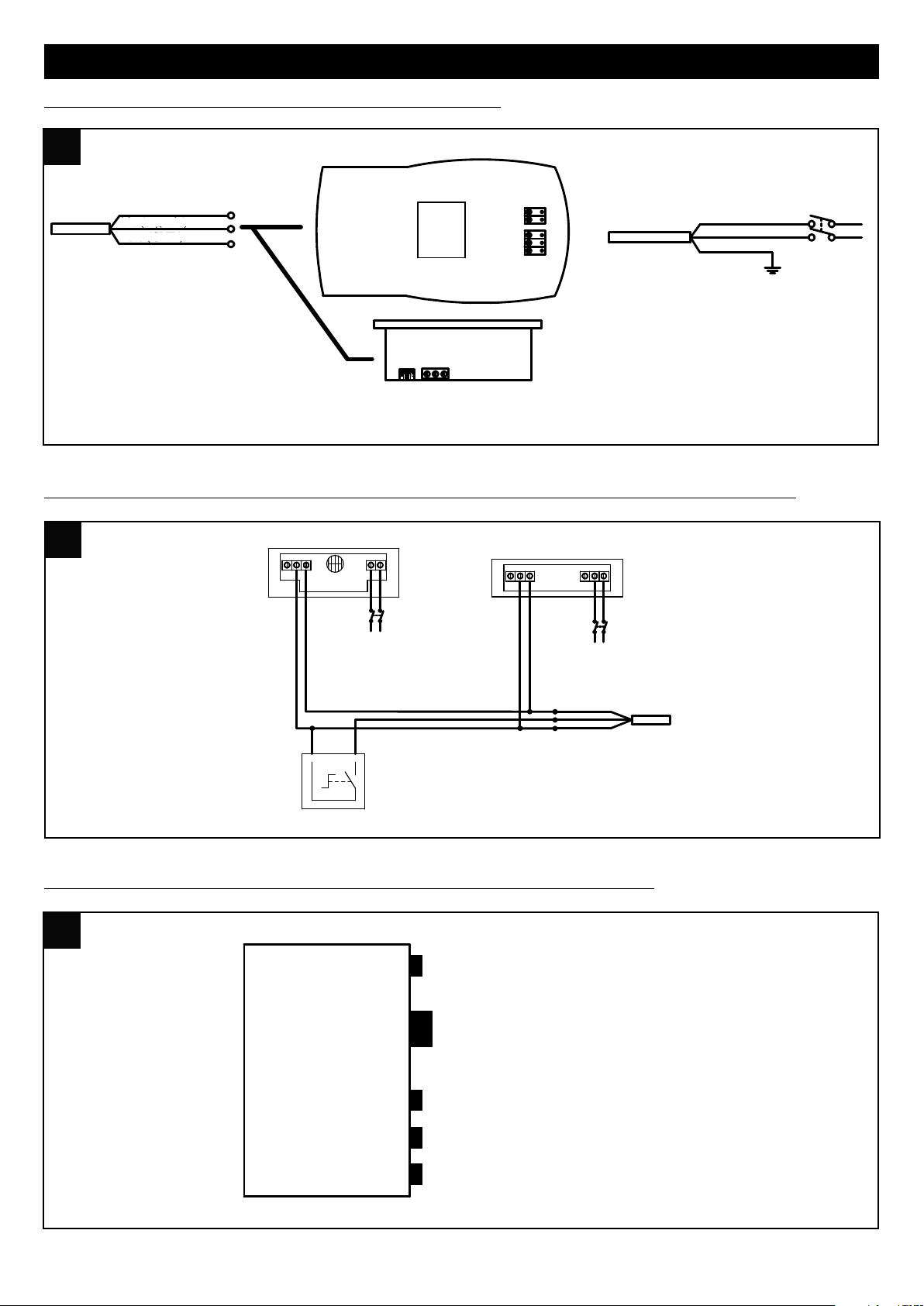
Vort HRI Phantom electrical connections: Installer/User Panel
INSTALLER/USER PANEL
Brown
Blue (signal)
Black (GND)
POWER SUPPLY
Vort HRI Phantom electrical connections: connecting the signal cable to Vortice and ON-OFF sensors
Vort HRI Phantom electrical connections: HRI PHANTOM cable wiring box outputs
A = CONTROL PANEL CABLE
18
B = POWER SUPPLY CABLE
C = ANTIBACTERIAL DEVICE CABLE (OPTIONAL)
D = EXTERNAL SIGNAL CABLE
E = PREHEATER CABLE (OPTIONAL)
Page 19

ENGLISH
e
sc set
10 10
By-Pass
/
°C
1
2345
6
7
P
1P2
P
1/P2
Prg
A
B
C
D
E
FILT
11 11
8 9 10 11 12 13
14
15
16 17 18 19
1 2 3 4 5 6 7
20
Use
In B.P. models, when the appliance is switched on and has been running for 2 minutes, both motors will stop to allow
repositioning of the bypass valve. The motors will start up again after approximately 1 minutes.
N.B. This is a normal system procedure and should not be perceived as a malfunction.
The appliance is wired to a special dedicated control panel, the functions of which are described further on.
This model can be used in combination with a Vortice preheater, which must be fitted and set up by the installer.
The minimum distance of the preheater from the appliance is 500 mm.
User panel functions
General (fig.10)
A = “UP” button: list up
B = “DOWN” button: list down
C = SET button: acquire data
D = ESC button: exit
E = display
This model comes with a panel which offers the user control of
the parameters:
- on/off
- current time/day
- operating speed
- required room temperature
- selection of bypass function
The function of the ESC button, unless otherwise stated, is always that of quitting without saving data.
Summary of icons displayed on the panel (Fig.11)
1-7 day of the week: 1=Monday, 2=Tuesday, etc.
8 filter alarm: this icon lights up to warn that the filters should
be replaced within two months; if the filters are not renewed
by the end of this period, the filter error message Filt appears
(see "View alarm menu").
9 no-frost function: the icon lights up permanently when the
no-frost procedure is active; the icon will flash to indicate a
“no-frost timeout”: in this instance the no-frost procedure has
proved insufficient and the appliance goes into protected
mode for one hour, with the motors stopped, following which
the system will restart the machine.
10 time profile P1: (see “User menu”).
11 time profile P2: (see “User Menu”).
12 HA
13 -14 current fan speed: with the appliance in operation, the icons light up steadily to indicate which of the 3 speeds is
currently selected.
15 system standby status: the icon lights up permanently when the appliance is in standby (powered up, but with the
motors at a standstill); the icon will flash to indicate that the appliance has reverted to standby after being programmed
(see “Program time profiles”); if the icon lights up and is accompanied by the message “OFF” on the right of the
display, this means that the appliance has been switched off remotely (when connected to a home automation
system).
16 the icon flashes to indicate that an alarm condition has been triggered; this indicates that an alarm with no manual
reset has been tripped (see “View alarms menu”) .
19
Page 20

ENGLISH
esc set
By-Pass
/
°C
1234567
FILT
P1 P2
P1/P2
Prg
12 12
esc set
By-Pass
/ ° C
1234567
FILT
P1 P2
P1/P2
Prg
13 13
esc set
By-Pass
/ ° C
1234567
FILT
P1 P2
P1/P2
Prg
14 14
17 bypass function: : the icon indicates: (see also "Activation of bypass function" paragraph) off: bypass deactivated
permanently alight: bypass opened manually blinking: bypass opened automatically via software (in this case the
bypass cannot be closed manually).
18 °C indoor temperature
19 view outdoor temperature, °C
Switching on/off (fig.12)
The appliance is switched on and off by pressing and holding
the DOWN button on the panel.
Setting the time/day (fig.13)
Selezione velocità (fig.14).
Before proceeding with the steps indicated below, press the
ESC button to exit and return to the initial menu.
The current time and day can be set as follows:
- press the UP and DOWN buttons together briefly;
- press the UP or DOWN button repeatedly to select the "hours”
setting (HH);
- press the SET button briefly to retain the “hours” setting and
move on to the “minutes” setting (MM);
- press the UP or DOWN button repeatedly to select the
"minutes”;
- press the SET button briefly to retain the “minutes” setting and
move on to the “day” setting (dAy);
- press the UP or DOWN button repeatedly to select the "day”
setting;
- press the SET button briefly to retain the “day” setting and
quit.
Before proceeding with the steps indicated below, press the
ESC button to exit and return to the initial menu.
The operating speed is preset during appliance configuration,
and can be selected by pressing the UP button briefly (1=min.
speed, 2=med. speed, 3=max. speed).
20
Page 21

ENGLISH
esc set
B
y-Pass
/
°C
1234567
F
ILT
P1 P2
P1/P2
Prg
15 15
esc set
By-Pass
/
°C
1234567
FILT
P1 P2
P1/P2
Prg
16 16
esc set
By-Pass
/ ° C
1234567
FILT
P1 P2
Prg
17 17
HA
esc set
By-Pass
/ ° C
12345
6
7
FILT
P2
Prg
18 18
P1
HA
Set required room temperature (fig.15).
Activate “bypass” function (fig.16)
Before proceeding with the steps indicated below, press the
ESC button to exit and return to the initial menu.
The preferred room temperature can be selected as follows:
- press and hold the SET button
- press the SET button briefly (the current value flashes)
- select the required value using the UP and DOWN buttons
- press the SET button briefly to retain the setting
- press the ESC button briefly to exit.
The purpose of the bypass function is to ventilate the apartment
without heat transfer. With the bypass valve open, air can be
introduced directly from outside, without passing through the
heat exchanger. The flow of air vented from inside continues to
pass through the heat exchanger.
Before proceeding with the steps indicated below, press the
ESC button to exit and return to the initial menu.
The “bypass” function can be forced by pressing and holding
the ESC button. The corresponding "money box" icon will light
up.
Activate time/outdoor temperature display (fig.20)
User menu
Before proceeding with the steps indicated below, press the
ESC button to exit and return to the initial menu.
The current values of the "time" and "outdoor temperature"
parameters can be viewed in alternation by pressing the ESC
button briefly.
Before proceeding with the steps indicated below, press ESC to
exit and return to the opening screen. As a rule, the parameters
relative to the various options are selected by pressing SET (this
causes the current value to blink), then scrolling through the
available values with the UP and DOWN buttons, and pressing
SET again to confirm the new value. The UP and DOWN buttons
are also used to scroll through the different options or
parameters. The main user menu can be viewed by pressing
and holding ESC and SET at one and the same time. The
options of the menu are:
21
Page 22

ENGLISH
esc set
By-Pass
/ ° C
1234567
FILT
P2
Prg
19 19
P1
HA
esc set
By-Pass
/ ° C
1234567
FILT
P2
Prg
20 20
P1
HA
- PROF: settings for operation with time profiles:
P1, used to program one period of operation per day, with a start time, an end time and a fan speed;
P2, used to program two periods of operation per day, each with a start time, an end time and a fan speed. The user
can allocate a different profile to each day of the week.
- HA: settings for operation in HA mode: available only on appliances equipped with HA module, and only if operation of
the main system with time profiles has not been enabled.
- SERV: service (option available only to the installer)
PROF option
Selecting HA by pressing SET, the settings for HA operating
mode are accessed. The parameters are:
- En (Enable): possible values are: ON: enables operation with
profiles (and as noted above, automatically disables any
possibility of operation in HA mode) OFF: disables operation
with profiles.
If EN ON has been selected, the following parameters are also
enabled:
- ST: start time, profile P1 interval
- END: end time, profile P1 interval
- SP: speed, profile P1: possible values are 1, 2, 3
- ST1: start time, profile P2 interval 1
- EN1: end time, profile P2 interval 1
- SP1: speed, profile P2 interval 1: possible values are 1, 2, 3
- ST2: start time, profile P2 interval 2
- EN2: end time, profile P2 interval 2
- SP2: speed, profile P2 interval 2: possible values are 1, 2, 3
- MON: allocation of profile to Monday: possible values are P1 and P2
- TUE: allocation of profile to Tuesday: possible values are P1 and P2
- WED: allocation of profile to Wednesday: possible values are P1 and P2
- THU: allocation of profile to Thursday: possible values are P1 and P2
- FRI: allocation of profile to Friday: possible values are P1 and P2
- SAT: allocation of profile to Saturday: possible values are P1 and P2
- SUN: allocation of profile to Sunday: possible values are P1 and P2
HA Option
This option is available only on models equipped with HA
module, and only if operation of the main system with time
profiles has not been enabled. Selecting HA by pressing SET,
the settings for HA operating mode are accessed. The
parameters are:
- En (Enable): possible values are:
PROF: enables HA mode with profiles
ON: enables HA mode continuously
OFF: disables HA mode
HOL: enables HOLIDAY mode: two hours antibacterial
operation per day, two hours refresh, 20 hours stand-by.
If EN PROF has been selected, the following parameters are
also enabled:
- ST: start time, profile P1 interval
- END: end time, profile P1 interval
- SP: speed, profile P1: possible values are 1, 2, 3
22
Page 23

esc set
B
y-Pass
/ ° C
1234567
FILT
P1 P2
P1/P2
Prg
21 21
ENGLISH
- ST1: start time, profile P2 interval 1
- EN1: end time, profile P2 interval 1
- ST2: start time, profile P2 interval 2
- EN2: end time, profile P2 interval 2
- MON: allocation of profile to Monday: possible values are P1 and P2
- TUE: allocation of profile to Tuesday: possible values are P1 and P2
- UED: allocation of profile to Wednesday: possible values are P1 and P2
- THR: allocation of profile to Thursday: possible values are P1 and P2
- FRY: allocation of profile to Friday: possible values are P1 and P2
- SAT: allocation of profile to Saturday: possible values are P1 and P2
- SUN: allocation of profile to Sunday: possible values are P1 and P2
View alarm menu (fig.21)
Before proceeding with the steps indicated below, press the
ESC button to exit and return to the initial menu. The indication
of any alarm conditions that may have been tripped can be
displayed as follows:
--press and hold the SET button
--press and release the UP or DOWN button to view ALRM
menu
--press and release the SET button to view the active error code
The various alarm situations that can affect the system are
displayed on the user panel as follows:
ti: indoor temperature sensor faulty; contact Technical Support
for assistance;
tout: outdoor temperature sensor faulty; contact Technical
Support for assistance;
te: exhaust air temperature sensor faulty; contact Technical Support for assistance;
preh: preheater faulty or missing (if applicable); contact Technical Support for assistance;
Hito: outdoor temperature higher than 45 °C; contact Technical Support for assistance;
Hiti: indoor temperature higher than 45 °C; contact Technical Support for assistance;
Filt: clogged filters need replacing (2 months). Once new filters have been fitted, the error can be reset by the user: this
is done simply by pressing and holding the UP and DOWN buttons together.
N.B. Manually resettable errors can be removed by pressing and holding the UP and DOWN buttons together.
23
Page 24

ENGLISH
22 22
Maintenance / cleaning
Before commencing any servicing operation, make sure that the appliance is disconnected from the electrical power
supply.
Dismantling and assembly are special maintenance operations and must be entrusted to professional technicians.
Filters
Recommended maintenance intervals:
because levels of air pollution depend typically on
geographical location and are variable, the life of the filters will
be similarly variable. With this general consideration in mind,
the following filter maintenance intervals are recommended:
Inspect filters: every 50/60 days; replacement of filters: after
3/24 months (depending on the value set by the installer) a
pre-alarm message will appear on the display to remind the
user of the need for the filters to be replaced. The filters must
be replaced within 2 months after this message appears; at
the end of the 2 months, the filters clogged alarm (Filt) will be
activated. When the error is reset (as described in "View alarm
menu" paragraph), the counter will also be reset.
N.B. Failure to clean or replace filters can seriously affect
system efficiency, causing: - increased pressure losses in the
air circulation system and reduced airflow; - drop in system
performance and comfort levels caused by pressure losses.
N.B. Clogged air filters are the most frequent cause of the
appliance locking up: (Filt)
Removing the filters from Vort HRI Phantom models: fig 22
Important information concerning the environmentally compatible disposal
IN CERTAIN EUROPEAN UNION COUNTRIES THIS PRODUCT DOES NOT FALL WITHIN THE REQUIREMENTS OF
THE NATIONAL LAWS IMPLEMENTING DIRECTIVE WEEE, AND IN THESE COUNTRIES THE PRODUCT IS NOT
SUBJECT TO SEPARATE DISPOSAL OPERATIONS AT THE END OF ITS WORKING LIFE.
This product conforms to EU Directive2002/96/EC.
This appliance bears the symbol of the barred waste bin. This indicates that, at the end of its useful life, it
must not be disposed of as domestic waste, but must be taken to a collection centre for waste electrical
and electronic equipment, or returned to a retailer on purchase of a replacement.
It is the user's responsibility to dispose of this appliance through the appropriate channels at the end of its
useful life. Failure to do so may incur the penalties established by laws governing waste disposal.
Proper differential collection, and the subsequent recycling, processing and environmentally compatible disposal of waste
equipment avoids unnecessary damage to the environment and possible related healthrisks, and also promotes recycling
of the materials used in the appliance.
For further information on waste collection and disposal, contact your local waste disposal service, or the shop from
which you purchased the appliance.
Manufacturers and importers fulfil their responsibilities for recycling, processing and environmentally compatible disposal
either directly or by participating in collective systems.
24
Page 25

FRANCAIS
Description et mode d’emploi
Vort HRI Phantom (ci-dessous « l'appareil ») est un système de ventilation centralisé à haut rendement énergétique avec
récupération de chaleur qui peut être monté à l'horizontale dans un faux plafond. L’appareil est commandé par un
système de gestion électronique avancé et équipé de ventilateurs à moteurs EC Brushless basse consommation.
Il contient un échangeur de chaleur qui assure un échange thermique à haut rendement (94 %).
L’appareil existe en 4 modèles avec des fonctions différentes :
Vort HRI Phantom (200 et 350) : version de base
Vort HRI Phantom B.P. (200 et 350) : version avec fonction supplémentaire By Pass.
(Voir paragraphe Utilisation pour la description détaillée des fonctions).
Ces appareils ont été conçus pour un usage domestique et commercial.
Sécurité
Attention:
ce symbole indique la nécessité de prendre
!
quelques précautions pour la sécurité de l‘utilisateur
• Suivre les consignes de sécurité afin d'éviter tout risque pour l'utilisateur.
• Ne pas utiliser l'appareil pour une autre fonction que celle qui est exposée dans ce livret.
• Après avoir sorti l'appareil de son emballage, vérifier son intégrité : dans le doute, s'adresser à un professionnel qualifié
ou à un service après-vente agréé Vortice.
• Ne pas laisser les composants de l'emballage à la portée des enfants ou de personnes inexpérimentées.
• L'utilisation des appareils électriques implique le respect de quelques règles fondamentales notamment :
ne pas toucher l'appareil avec les mains mouillées ou humides ;
ne pas le toucher pieds nus.
• Ne pas utiliser l'appareil près de substances ou de vapeurs inflammables (alcool, insecticide, essence, etc).
• Conserver l'appareil hors de portée des enfants et des personnes inexpérimentées s'il est débranché du réseau
électrique et qu'on ne souhaite plus l'utiliser.
• Cet appareil peut être utilisé par des enfants âgés de plus de 8 ans et des personnes porteuses d'un
handicap physique, sensoriel ou mental, ou encore sans expériences ou connaissances
spécifiques, à condition de travailler sous supervision ou après avoir reçu les instructions
d'utilisation de l'appareil en toute sécurité, et après en avoir parfaitement compris les dangers. Les
enfants ne doivent pas jouer avec l'appareil. Le nettoyage et l'entretien réservés à l'utilisateur ne
doivent pas être effectués par des enfants sans surveillance.
Avertissement:
ce symbole indique la nécessité de prendre
!
quelques précautions pour la sécurité du produit
• Ne pas modifier l'appareil.
• Respecter les consignes d'entretien pour éviter d'endommager l'appareil ou de l'user prématurément.
• Ne pas exposer l'appareil aux agents atmosphériques (pluie, soleil, etc.).
• Ne rien poser sur l'appareil.
• Le nettoyage interne de l'appareil doit être confié à un technicien spécialisé.
• Contrôler régulièrement l'intégrité de l'appareil. En cas de problème, ne pas utiliser l'appareil et contacter
immédiatement un Service après-vente agréé Vortice.
• En cas de dysfonctionnement ou de panne de l'appareil, s'adresser immédiatement à un Service après-vente agréé
Vortice et demander, pour toute réparation, l'utilisation de pièces détachées d'origine Vortice.
• Si le câble d'alimentation est endommagé, le faire remplacer immédiatement auprès d'un centre de Service après-vente
agréé Vortice.
• Si l'appareil tombe ou subit un choc violent, le faire vérifier immédiatement auprès d'un centre de Service Après-vente
agréé Vortice.
• Installer l'appareil de sorte que personne ne puisse se trouver à proximité de pièces en mouvement ou sous tension
pendant son fonctionnement normal.
• En cas de :
démontage de l'appareil, avec les outils appropriés ;
extraction de l'échangeur de chaleur ;
25
Page 26

FRANCAIS
1 1AA 2 2
A
B
C
D
extraction du module des moteurs ;
éteindre préalablement l'appareil et le débrancher du secteur.
• L'installation électrique à laquelle l'appareil est branché doit être conforme aux normes en vigueur.
• Ne brancher l'appareil au secteur/à la prise électrique que si les caractéristiques du circuit ou de la prise sont adaptées
à sa puissance maximale. Dans le cas contraire, s'adresser immédiatement à un technicien qualifié.
• Couper l'électricité par l'interrupteur général de l'installation dans les cas suivants :
anomalie pendant le fonctionnement
nettoyage extérieur ;
l'appareil ne doit plus être utilisé pendant une période de
courte ou de longue durée.
• L'appareil ne doit pas être utilisé comme démarreur de
chauffe-bain, poêle, etc, et son évacuation ne doit pas
déboucher dans les conduites d'eau chaude de ces
appareils.
• Son évacuation doit déboucher directement à l'extérieur,
dans un conduit spécial.
• Le débit d'air extrait doit être propre (sans graisse, suie,
agents chimiques ou corrosifs, mélanges explosifs ou
inflammables).
• Ne pas couvrir ni boucher l'aspiration ni le refoulement de
l'appareil afin de permettre un passage optimal de l'air.
• Température maximale de service : 45° C.
• Les caractéristiques électriques du réseau doivent
correspondre à celles qui figurent sur la plaquette A (fig.1).
• L’installation de l'appareil doit être réalisée par un technicien qualifié.
• Pour l'installation de l'appareil, prévoir un interrupteur omnipolaire ayant une distance d'ouverture
entre les contacts égale ou supérieure à 3 mm.
Structure et équipement de série
Les principales pièces qui composent l'appareil sont les suivantes :
• un carter extérieur réalisé en acier galvanisé ;
• un échangeur de chaleur en polystyrène à flux à contre-courant dont la forme particulière permet d'obtenir un échange
thermique à très haut rendement (jusqu'à 94 %) ;
• deux moteurs sans balai basse consommation à vitesse variable (3 vitesses prédéfinies) ;
• un contrôleur électronique qui gère l'alimentation, la commande et le contrôle de l'appareil ;
• deux actionneurs thermiques qui gèrent l'ouverture de la vanne de bypass (selon le modèle) ;
• tableau de commande déporté ;
• 3 capteurs de température ;
• 2 filtres F5 ;
• 4 attaches pour la pose au plafond.
Références des bouches de passage de l'air (fig.2)
A : Refoulement d'air propre dans l'habitation
B : Extraction de l'air impur de l'habitation
C : Aspiration d'air frais de l'extérieur
D : Refoulement de l'air impur vers l'extérieur
26
Page 27

FRANCAIS
3 3
4 4
5 5
1
2
Installation
N.B. L’appareil n'est pas destiné à être installé à l'extérieur.
L'installation de l'appareil doit être conforme aux normes de
sécurité en vigueur dans le pays de destination et aux
instructions de ce manuel. L’appareil doit être installé sur une
surface ou une cloison à l'intérieur de l'habitation,
suffisamment solide pour supporter son poids (max 25 kg
mod. 200, max 38 kg mod. 350).
Afin d'optimiser et de simplifier les connexions de l'appareil,
tenir compte de la position du boîtier électrique d'où sortent
les câbles (fig.3).
Montage au plafond
Il existe plusieurs possibilités de montage : Vortice suggère
d'appliquer l'appareil au plafond avec les attaches spéciales
fournies (fig.4).
Dans tous les cas, après le montage, s'assurer que l'appareil
est parfaitement à niveau et qu'il peut fonctionner
normalement. Les conduites utilisées pour les canalisations
doivent être correctement dimensionnées.
Les conduites qui communiquent avec l'extérieur doivent être
isolées contre les variations thermiques et protégées contre
les vibrations.
Les conduites d'aspiration et de refoulement, qui ont un
diamètre nominal de 125 mm (mod. 200), et de 150 mm (mod.
350), doivent être fixées aux bouches de l'appareil avec des
colliers ou d'autres systèmes de fixation appropriés.
Si l'évacuation s'effectue par le toit, l'installation d'un
système contre la condensation et l'infiltration des eaux de
pluie est obligatoire.
Si l'entrée d'air s'effectue par le toit, l'installation d'un
système contre la condensation et l'infiltration des eaux de pluie est obligatoire.
Évacuation de la condensation
De la condensation s'accumule au fond de l'appareil pendant
son fonctionnement dans un double réservoir muni de deux
décharges vers l'extérieur.
Les points de raccordement sont situés au fond de l'appareil
(fig. 5). Pour réaliser l'évacuation de la condensation,
brancher aux bouches deux tuyaux flexibles de 19 mm de
diamètre intérieur.
Pour empêcher la formation de bulles d'air, réaliser un siphon
avec le tube qui sort de l'évacuation n° 1 sur l'appareil, voir
fig. 5b.
Couper l'extrémité du tuyau en diagonale.
N.B.
Pour réaliser le siphon, respecter les cotes indiquées sur la
fig. 5c ; dans le cas contraire, le bon fonctionnement de
l'appareil n'est pas garanti.
Pour l'évacuation de la condensation, il est possible d'utiliser
l'égout de la maison.
27
Page 28

FRANCAIS
5a 5a
1
2
NO
5b 5b
OK
12
5c 5c
h > 50 mm∆
≥ 60 mm
6 6
B
A
1
2
3
4
5
6,7
Accessibilité
L'appareil doit être facilement accessible pour les interventions de service/maintenance. Le faux plafond dans lequel
l'appareil est installé doit comporter une trappe d'inspection de dimensions adaptées permettant d'ouvrir le
compartiment des composants électriques et électroniques et celui des filtres. Il n'est donc pas nécessaire de sortir
l'appareil du faux plafond pour l'entretien courant (remplacement des filtres) ou les interventions exceptionnelles
(remplacement d'un ventilateur ou du contrôleur électronique).
Entrées boîtier électrique
Fig 6A
1: Préchauffeur (pour connecter le préchauffeur, il est
nécessaire d'ouvrir le groupe électronique, de connecter les
connecteurs gris et de configurer le logiciel (opérations à la
charge de l'installateur)
2: Interrupteurs
4: Alimentation
5: Afficheur
Fig 6B
6,7: Actionneurs thermiques bypass
28
Page 29

FRANCAIS
7 7
ALIMENTAZIONE
GV - Y/G
L
N
marrone / brown
blu / blue
nero (GND)
blu (segnale)
marrone (+12V dc)
brown / +12V dc
blue / signal
black/ GND
SKP 10
black/ GND
blue / signal
brown / +12V dc
SKW 22
PANNELLO INSTALLATORE/UTENTE
8 8
2
3
0
V
5
0
H
z
L
N
N
L
1
2
3
S
e
n
s
o
r
e
C
S
M
O
K
E
/
C
T
E
M
P
3
2
1
T
m
N
L
2
3
0
V
5
0
H
z
N
L
S
e
n
s
o
r
e
C
P
I
R
/
C
H
C
S
marrone
2
1
S
e
l
e
t
t
o
r
e
O
N
-
O
F
F
r
e
m
o
t
o
verde
bianco
C
a
v
o
d
i
s
e
g
n
a
l
e
e
s
t
e
r
n
o
9 9
A
B
C
D
E
A = CAVO PANNELLO DI CONTROLLO
B = CAVO ALIMENTAZIONE
C = CAVO DISPOSITIVO ANTIBATTERICO (OPTIONAL)
D = CAVO SEGNALE ESTERNO
E = CAVO PRE HEATHER (OPTIONAL)
Connexions électriques Vort HRI Phantom: Tableau Installateur/Utilisateur
ABLEAU INSTALLATEUR/UTILISATEUR
T
Connexions électriques Vort HRI Phantom: Connexion câble signal avec capteurs Vortice et ON-OFF Connexions électriques
ALIMENTATION
Connexions électriques Vort HRI Phantom : Sortie câbles HRI PHANTOM du boîtier de câblage
A = CÂBLE TABLEAU DE COMMANDE
B = CORDON D'ALIMENTATION
C = CÂBLE DISPOSITIF ANTIBACTÉRIEN (OPTION)
D = CÂBLE SIGNAL EXTÉRIEUR
E = CÂBLE PRÉCHAUFFEUR (OPTION)
29
Page 30

FRANCAIS
esc set
10 10
B
y-Pass
/
°C
1234567
P
1P2
P1/P2
Prg
A
B
C
D
E
FILT
11 11
8 9 10 11 12 13
14
15
16 17 18 19
1 2 3 4 5 6 7
20
Mode d’emploi
Après la mise en marche et 2 minutes de fonctionnement, les deux moteurs des appareils B.P. s'arrêtent pour permettre
le repositionnement de la vanne de by-pass. Ils se remettent en marche 1 minute plus tard.
N.B. cette procédure est normale et ne doit pas être considérée comme un dysfonctionnement.
Le contrôle de l'appareil se fait à partir d'un tableau de commande spécial dont les fonctions sont décrites ci-dessous.
Il est possible d'ajouter un préchauffeur Vortice dont la mise en place doit être confiée à l'installateur.
La distance minimale entre le pré-chauffage et l'appareil est de 500 mm.
Fonctions du tableau utilisateur
Généralités (fig.10)
A = touche « UP » : monte
B = touche « DOWN » : descend
C = touche SET : saisie des données
D = touche ESC : quitter
E = afficheur
L'utilisateur dispose d'un tableau pour la gestion des
paramètres - marche/arrêt
- heure/jour courants
- vitesse de fonctionnement
- température ambiante requise
- forçage en fonction by-pass.
La fonction du bouton ESC, sauf indication diverse, est toujours la sortie de l'application sans sauvegarde des données.
Tableau récapitulatif des icônes du tableau
(fig.11)
1÷7 jour de la semaine : 1=lundi, 2=mardi, etc.
8 alarme filtres : lorsque l'icône s'allume, elle indique qu'il faut
remplacer les filtres dans les deux mois suivants ; si les filtres
ne sont pas remplacés dans ce délai, le système signale
l'erreur filtres Filt (voir paragraphe Affichage menu alarmes)
9 fonction no-frost : lorsque l'icône s'allume, elle indique que la
procédure de dégivrage est active ; lorsque l'icône clignote,
elle indique une situation de No-frost timeout : dans ce cas,
la procédure de dégivrage n'est pas suffisante et l'appareil se
met en sécurité pendant une heure, moteurs éteints, puis le
système réactive l'appareil dès que possible.
10 profil horaire P1 : (voir paragraphe “Menu Utilisateur”)
11 profil horaire P2 : (voir paragraphe “Menu Utilisateur”)
12 HA
13 -14 vitesse de fonctionnement courante : les icônes allumées indiquent sur laquelle des 3 vitesses fonctionne l'appareil.
15 stand-by du système : l’icône allumée indique que l'appareil est en stand-by (allumé avec moteurs éteints) ; l’icône
clignote pour indiquer que l'appareil est en stand-by à la suite de la programmation des tranches horaires (voir
paragraphe Définition des profils horaires) ; si l'inscription OFF apparaît à droite de l'écran lorsque l'icône s'allume,
l'appareil a été éteint à distance dans le cadre d'un système domotique.
16 l’icône clignote pour signaler la présence d'une alarme ; l’icône reste allumée en permanence pour signaler qu'une
30
alarme, qui ne peut être acquittée manuellement, s'est déclenchée (voir paragraphe « Affichage menu alarmes »).
Page 31

FRANCAIS
esc set
By-Pass
/
°C
1234567
FILT
P1 P2
P1/P2
Prg
12 12
esc set
By-Pass
/ ° C
1234567
FILT
P1 P2
P1/P2
Prg
13 13
esc set
By-Pass
/ ° C
1234567
FILT
P1 P2
P1/P2
Prg
14 14
17 fonction by-pass : l’icône indique : (consulter également le paragraphe Activation fonction By-pass) éteinte : by-pass
désactivée allumée en permanence : by-pass ouverte au moyen de la commande manuelle clignotante : by-pass
ouverte automatiquement via le logiciel (dans ce cas, il n'est pas possible de fermer la by-pass manuellement)
18 degrés Celsius température intérieure
19 affichage de la température extérieure en degrés Celsius
Marche/arrêt (fig.12)
Pour allumer ou éteindre l'appareil, exercer une pression
prolongée sur la touche Down du tableau.
Réglage heure/jour (fig.13)
Sélection des vitesses (fig.14).
Avant de suivre les étapes ci-dessous, appuyer sur la touche
ESC pour sortir et se positionner dans le menu principal.
Pour saisir le jour et l'heure courants, procéder de la façon
suivante :
- appui bref simultané sur les boutons up et down
- appui bref sur les boutons up et down pour régler l'heure (HH) ;
- appui bref sur le bouton SET pour valider l'heure et passer aux
minutes (MM) ;
- appui bref sur les boutons up et down pour régler les minutes ;
- appui bref sur le bouton SET pour valider les minutes et passer
au jour (dAy) ;
- appui bref sur les boutons up et down pour régler le jour ;
- appui bref sur le bouton SET pour valider le jour et sortir.
Avant de suivre les étapes ci-dessous, appuyer sur la touche
ESC pour sortir et se positionner dans le menu principal.
La vitesse de fonctionnement, prédéfinie pendant la
configuration, peut être sélectionnée par une appui bref sur la
touche up (1=Vit min, 2=Vit moy, 3=Vit max).
31
Page 32

FRANCAIS
esc set
By-Pass
/ ° C
1234567
FILT
P
1P2
P
1/P2
P
rg
15 15
esc set
By-Pass
/ ° C
1234567
FILT
P1 P2
P1/P2
Prg
16 16
esc set
By-Pass
/ ° C
1234567
FILT
P1 P2
Prg
17 17
HA
Réglage de la température ambiante requise (fig.15).
Activation de la fonction “bypass“ (fig.16)
Avant de suivre les étapes ci-dessous, appuyer sur la touche
ESC pour sortir et se positionner dans le menu principal.
La température ambiante choisie peut être sélectionnée de la
façon suivante :
- appui prolongé sur le bouton SET
- appui bref sur le bouton SET (la valeur actuelle clignote)
- sélection de la valeur choisie avec les boutons up et down
- appui bref sur le bouton SET pour saisir la valeur
- appui bref sur le bouton ESC pour sortir
La fonction de by-pass permet d'aérer l'habitation sans transfert
de chaleur. L’ouverture de la vanne de by-pass permet de
transférer directement l'air provenant de extérieur et évite le
passage dans l'échangeur de chaleur. Par contre, l'air expulsé
de l'habitation continue à passer dans l'échangeur.
Avant de suivre les étapes ci-dessous, appuyer sur la touche
ESC pour sortir et se positionner dans le menu principal.
La fonction by-pass peut être forcée par une pression prolongée
sur le bouton ESC. L'icône “tirelire” s'allume.
Activation affichage heure/température extérieure (fig.17)
Avant de suivre les étapes ci-dessous, appuyer sur la touche
ESC pour sortir et se positionner dans le menu principal.
Il est possible d'afficher alternativement les paramètres heure
et température extérieure en appuyant brièvement sur le
bouton ESC.
32
Page 33

FRANCAIS
esc set
By-Pass
/ ° C
1234567
FILT
P2
Prg
18 18
P1
H
A
esc set
By-Pass
/ ° C
1234567
FILT
P2
Prg
19 19
P1
HA
Menu utilisateur
Avant de suivre les étapes ci-dessous, appuyer sur la touche
ESC pour sortir et se positionner sur la page initiale. Les
paramètres concernant les différentes options peuvent être
généralement configurés moyennant l'enfoncement de SET (la
valeur actuelle commence à clignoter), la sélection des
différentes valeurs au moyen des boutons UP et DOWN et le
réenfoncement de SET pour obtenir la nouvelle valeur. Les
boutons UP et DOWN permettent également de faire défiler les
différents paramètres ou options. L'enfoncement simultané des
boutons ESC et SET permet de visualiser le menu général de
l'utilisateur. Les options du menu sont les suivantes :
- PROF : configurations fonctionnement avec profils horaires:
P1 permet de définir un intervalle de fonctionnement par jour, avec un horaire de début, de fin et une vitesse ; P2 permet
de définir deux intervalles de fonctionnement par jour avec, chacun, un horaire de début, de fin et une vitesse. Il est
possible d'attribuer un profil différent à chaque jour de la semaine.
- HA : configurations fonctionnement HA : présente uniquement sur les appareils dotés du module HA, et à condition que
le fonctionnement du système principal avec profils horaires ne soit pas activé.
- SERV : service (option réservée à l'installateur)
Option PROF
Pour entrer dans les configurations des profils horaires,
sélectionner PROF au moyen du bouton SET. Les paramètres
sont les suivants :
- En (Enable) : les valeurs possibles sont les suivantes :
ON : permet l'activation du fonctionnement avec profils (et,
comme indiqué ci-dessus, l'éventuel fonctionnement en
mode HA est automatiquement désactivé)
OFF : permet la désactivation du fonctionnement avec profils.
Les paramètres suivants sont eux aussi activés en cas de
sélection de EN ON :
- ST: horaire début intervalle de profil P1
- END: horaire fin intervalle de profil P1
- SP: vitesse profil P1 : les valeurs possibles sont 1, 2, 3
- ST1 : horaire début intervalle 1 de profil P2
- EN1 : horaire fin intervalle 1 de profil P2
- SP1: vitesse intervalle 1 de profil P2 : les valeurs possibles sont 1, 2, 3
- ST2 : horaire début intervalle 2 de profil P2
- EN2 : horaire fin intervalle 2 de profil P2
- SP2: vitesse intervalle 2 de profil P2 : les valeurs possibles sont 1, 2, 3
- MON: attribution du profil au lundi : les valeurs possibles sont P1 et P2
- TUE: attribution du profil au mardi : les valeurs possibles sont P1 et P2
- UED: attribution du profil au mercredi : les valeurs possibles sont P1 et P2
- THR: attribution du profil au jeudi : les valeurs possibles sont P1 et P2
- FRY: attribution du profil au vendredi : les valeurs possibles sont P1 et P2
- SAT: attribution du profil au samdi : les valeurs possibles sont P1 et P2
- SUN: attribution du profil au dimanche : les valeurs possibles sont P1 et P2
33
Page 34

FRANCAIS
esc set
By-Pass
/ ° C
1234567
FILT
P1 P2
P1/P2
Prg
21 21
esc set
By-Pass
/ ° C
1
234 5
6
7
FILT
P2
P
rg
20 20
P1
HA
Cette option est disponible uniquement sur les modèles dotés
du module HA, et à condition que le fonctionnement du
système principal avec profils horaires ne soit pas activé.
Pour entrer dans les configurations de la modalité HA,
sélectionner HA au moyen du bouton SET. Les paramètres
sont les suivants:
- En (Enable) : les valeurs possibles sont les suivantes
PROF: active la modalité HA avec profils
ON: active la modalité HA continue
OFF: désactive la modalité HA
HOL: active la modalité HOLIDAY : deux heures de
fonctionnement antibactérien par jour, deux heures de
renouvellement de l'air, 20 heures de veille
Les paramètres suivants sont eux aussi activés en cas de
sélection de EN PROF :
- ST: horaire début intervalle de profil P1
- END: horaire début intervalle de profil P1
- ST1 : horaire début intervalle 1 de profil P2
- EN1 : horaire fin intervalle 1 de profil P2
- ST2 : horaire début intervalle 2 de profil P2
- EN2 : horaire fin intervalle 2 de profil P2
- MON: attribution du profil au lundi : les valeurs possibles sont P1 et P2
- TUE: attribution du profil au mardi : les valeurs possibles sont P1 et P2
- UED: attribution du profil au mercredi : les valeurs possibles sont P1 et P2
- THR: attribution du profil au jeudi : les valeurs possibles sont P1 et P2
- FRY: attribution du profil au vendredi : les valeurs possibles sont P1 et P2
- SAT: attribution du profil au samdi : les valeurs possibles sont P1 et P2
- SUN: attribution du profil au dimanche : les valeurs possibles sont P1 et P2
Affichage menu alarmes (fig.21)
Avant de suivre les étapes ci-dessous, appuyer sur la touche ESC
pour sortir et se positionner dans le menu principal. Il est possible d'afficher les signaux d'alarme actifs de la façon suivante.
--appui prolongé sur le bouton SET
--enfoncement bref de UP ou DOWN de sorte à afficher le menu
ALRM
--appui bref sur le bouton SET pour afficher le code d’erreur actif
Le système peut présenter plusieurs situations d'alarme affichées
de la façon suivante sur le tableau de l'utilisateur.
ti : capteur de température intérieure en panne ; demander l'intervention de l'Assistance technique ;
tout : capteur de température extérieure en panne ; demander
l'intervention de l'Assistance technique ;
te : capteur de température air d'évacuation en panne ; demander l'intervention de l'Assistance technique ;
preh : préchauffeur en panne ou absent (selon modèle) ; demander l'intervention de l'Assistance technique ;
Hito : température extérieure supérieure à 45°C ; demander l'intervention de l'Assistance technique ;
Hiti : température intérieure supérieure à 45°C ; demander l'intervention de l'Assistance technique ;
Filt : remplacer les filtres colmatés (2 mois). Après avoir remplacé les filtres, l'utilisateur peut remettre la signalisation de
l'erreur à zéro : pour ce faire, appuyer longuement et en même temps sur les touches UP et DOWN.
N.B. Pour la remise à zéro manuelle des signalisations d'erreurs appuyer longuement sur les touches UP et DOWN.
Entretien / nettoyage
Avant toute opération, s'assurer que l'appareil est déconnecté du réseau électrique.
Le démontage et le remontage sont des opérations d'entretien exceptionnel qui sont réservées à des professionnels
qualifiés.
34
Page 35

FRANCAIS
22 22
Filtres
Intervalles d'entretien conseillés:
la durée des filtres varie avec le niveau de pollution de la zone géographique. Les intervalles d'entretien des filtres sont
donc les suivants.
Inspection des filtres : tous les 50/60 jours
remplacement des filtres : au bout de 3 ou 24 mois (selon la
programmation de l'installateur en phase d'installation),
l'afficheur visualise un message de pré-alarme qui signale à
l'utilisateur la nécessité de remplacer les filtres. Remplacer les
filtres dans les 2 mois qui suivent ce message ; au bout des 2
mois, l'alarme de filtres colmatés se déclenche (Filt). En
remettant l'erreur à zéro (explication au paragraphe Affichage
menu alarmes), le compteur se remet lui aussi à zéro.
N.B. Le défaut de nettoyage ou de remplacement des filtres
peut nuire gravement à l'efficacité de l'installation :
- augmentation des pertes de charge dans le circuit d'air et
réduction du débit d'air
- baisse de rendement de l'appareil et détérioration du confort
et de la qualité de l'air ambiant.
N.B. La saturation des filtres est la cause la plus fréquente de
blocage de l'appareil : (Filt)
Extraction des filtres modèles Vort HRI Phantom: fig 22
Information importante pour éliminer l'appareil en respectant l'environnement
DANS CERTAINS PAYS DE L’UNION EUROPÉENNE, CET APPAREIL N’ENTRE PAS DANS LE CHAMP DE
TRANSPOSITION DE LA DIRECTIVE DEEE, IL N’EXISTE DONC AUCUNE OBLIGATION DE COLLECTE
DIFFÉRENCIÉE À LA FIN DE SON CYCLE DE VIE.
Cet appareil est conforme à la Directive EU2002/96/EC.
Le symbole du bidon barré apposé sur l’appareil indique que, lors de sa mise au rebut, il doit être traité
séparément des déchets domestiques et remis à un centre de collecte différenciée pour équipements
électriques et électroniques ou au revendeur, lors de l’achat d’un nouvel appareil.
L’utilisateur est responsable de la remise de l’appareil à la fin de son cycle de vie aux structures de collecte
appropriées, sous peine des sanctions prévues par la loi en matière de traitement des déchets.
La collecte différenciée, en permettant de recycler l’appareil, de le retraiter et de l’éliminer en respectant l’environnement,
contribue à éviter la pollution du milieu et ses effets sur la santé et favorise la réutilisation des matériaux qui le composent.
Pour plus d’informations sur les systèmes de collecte existants, s’adresser au service local d’élimination des déchets ou
au magasin dans lequel l’appareil a été acheté.
Les producteurs et les importateurs satisfont à leurs obligations environnementales en matière de recyclage, de
traitement et d’élimination des déchets, directement ou en participant à un système collectif.
35
Page 36

DEUTSCH
Beschreibung und gebrauch
Vort HRI Phantom (nachfolgend als „Gerät“ bezeichnet) ist ein zentrales Lüftungssystem mit Wärmerückgewinnung und
hohem Wirkungsgrad, das horizontal an der abgehängten Decke installiert werden kann. Das Gerät besitzt ein
hochentwickeltes elektronisches Steuersystem und ist mit modernen Lüftern bestückt, die mit energiesparenden
kollektorlosen EC Motoren ausgestattet sind.
Der eingebaute Wärmetauscher garantiert eine Wärmeaustauscheffizienz bis zu 94%.
Das Gerät wird in 4 Modellen gebaut, die verschiedene Funktionen aufweisen:
Vort HRI Phantom (200 und 350): Basisversion
Vort HRI Phantom B.P. (200 und 350): Version mit zusätzlicher Bypass-Funktion.
(Siehe „Anwendung“ für eine detaillierte Beschreibung der verschiedenen Funktionen).
Diese Geräte sind zur Verwendung im Haushalt ausgelegt.
Sicherheit
Achtung:
dieses Symbol zeigt Vorsichtsmaßnahmen an
!
um Schäden am Bediener zu vermeiden
• Um Personenschäden zu vermeiden, sind die sicherheitsrelevanten Hinweise strikt einzuhalten.
• Das Gerät darf nicht für andere als in diesem Handbuch angeführte Zwecke eingesetzt werden.
• Überprüfen Sie das Gerät nach dem Auspacken auf Unversehrtheit. Wenden Sie sich im Zweifelsfall unverzüglich an
einen Fachmann oder ein autorisiertes Vortice-Kundendienstzentrum.
• Das Verpackungsmaterial nicht in Reichweite von Kindern oder Personen lassen, die sich damit schaden könnten.
• Beim Einsatz von Elektrogeräten jeder Art müssen einige Grundregeln stets beachtet werden, wie unter anderem:
Nicht mit nassen oder feuchten Händen berühren;
Nicht barfuß berühren.
• Das Gerät nicht in der Nähe entflammbarer Substanzen oder Dämpfe wie Alkohol, Insektizide, Benzin usw. verwenden.
• Sorgen Sie dafür, dass das außer Betrieb genommene Gerät nicht für Kinder oder behinderte Personen zugänglich ist,
die sich damit verletzen können.
• Kinder ab 8 Jahren und Personen mit eingeschränkten körperlichen, sensorischen oder geistigen
Fähigkeiten bzw. mangelnder Erfahrung und Kenntnis dürfen dieses Gerät nur unter Aufsicht oder
nach sicherer Unterweisung im Gebrauch des Geräts und nur, wenn sie über die hiermit
verbundenen Gefahren aufgeklärt wurden, bedienen.
• Kinder dürfen nicht mit diesem Gerät spielen.
• Die Reinigungs- und Wartungsarbeiten, die vom Benutzer selbst vorgenommen werden können,
dürfen nicht von unbeaufsichtigten Kindern durchgeführt werden.
Hinweis:
dieses Symbol zeigt Vorsichtsmaßnahmen an
!
um Schäden am Gerät zu vermeiden
• Keine Änderungen am Gerät vornehmen.
• Um Schäden am Gerät und/oder vorzeitigen Verschleiß zu vermeiden, sind die Wartungsanleitungen zu befolgen.
• Das Gerät keinen Witterungseinflüssen (Regen, Sonneneinstrahlung usw.) aussetzen.
• Keine Gegenstände auf dem Gerät abstellen.
• Das Geräteinnere darf nur von Fachpersonal gereinigt werden.
• Das Gerät regelmäßig auf seinen einwandfreien Zustand überprüfen. Bei festgestellten Mängeln das Gerät nicht mehr
benutzen und sofort den Vortice-Vertragskundendienst verständigen.
• Bei Betriebsstörungen und/oder defektem Gerät sofort den Vortice-Vertragskundendienst aufsuchen und für eine
eventuelle Reparatur die Verwendung von Vortice-Originalersatzteilen verlangen.
• Bei Schäden am Netzkabel sofort eine Vortice-Kundendienststelle verständigen und das Kabel austauschen lassen.
• Fällt das Gerät herunter oder wurde es starken Stößen ausgesetzt, muss es sofort vom Vortice-Vertragskundendienst
überprüft werden.
• Das Gerät muss so montiert werden, dass unter normalen Betriebsbedingungen niemand in die Nähe von beweglichen
oder spannungsführenden Teilen kommen kann.
• Vor:
dem Zerlegen des Geräts mit geeignetem Werkzeug;
36
Page 37

DEUTSCH
1 1AA 2 2
A
B
C
D
dem Herausziehen des Wärmetauschers;
dem Herausziehen des Motorenmoduls;
muss das Gerät abgeschaltet und vom Stromnetz getrennt werden.
• Die Elektroanlage, an die das Gerät angeschlossen wird, muss den geltenden Vorschriften entsprechen.
• Das Gerät nur dann an das Stromnetz anschließen, wenn die Stromfestigkeit der Anlage/Steckdose für die maximale
Leistung geeignet ist. Wenden Sie sich andernfalls umgehend an einen Elektrofachmann.
• Den Bedienschalter ausschalten, wenn:
eine Betriebsstörung festgestellt wird;
das Geräteäußere gereinigt werden muss;
das Gerät längere Zeit nicht benutzt wird.
• Das Gerät darf nicht als Brennbetriebsunterstützung für
Boiler, Öfen etc. benutzt werden. Die Abluft des Geräts darf
nicht in Warmluftleitungen derartiger Geräte geleitet werden.
• Die Fortluft muss über eine eigene Leitung direkt ins Freie
abgeleitet werden.
• Die Abluft muss sauber (d. h. frei von Fettpartikeln, Ruß,
chemischen oder korrosiven Substanzen, explosiven bzw.
brennbaren Mischungen) sein.
• Die Ansaug- und Ausblasöffnungen am Gerät dürfen weder
abgedeckt noch verstopft sein, damit ein optimaler
Luftdurchlass gewährleistet ist.
• Max. Betriebstemperatur: 45°C.
• Die elektrischen Daten des Stromnetzes müssen mit den
Angaben auf dem Schild A (Abb. 1) übereinstimmen.
• Das Gerät darf nur von qualifiziertem Fachpersonal installiert werden.
• Bei der Installation ist ein allpoliger Schalter mit einer Kontaktöffnungsweite von mindestens 3 mm
vorzusehen.
Aufbau und Ausstattung
Das Gerät setzt sich aus folgenden Hauptbestandteilen zusammen:
• Außengehäuse aus verzinktem Stahl;
• Wärmetauscher aus Polyester mit gegenläufigen Strömungsrichtungen, dessen Form eine hohe
Wärmeaustauscheffizienz gewährleistet (bis zu 94%);
• den beiden energiesparenden kollektorlosen Motoren mit einstellbarer Drehzahl (3 voreingestellte Drehzahlen);
• Elektronik für die Stromversorgung, Steuerung und Überwachung des Geräts;
• zwei Thermoaktoren, die das Öffnen des Bypassventils
regeln (sofern vorgesehen);
• Separate Bedienblende;
• 3 verschiedene Temperaturfühler;
• 2 Filter F5;
• 4 Haltebügel für die Deckenbefestigung
Bedeutung der Luftdüsen (Abb.2)
A: Zuführung der Zuluft in die Wohnung
B: Absaugen der Abluft aus der Wohnung
C: Frischluft-Ansaugung von außen
D: Fortluft-Ableitung ins Freie
37
Page 38

DEUTSCH
3 3
4 4
5 5
1
2
Installation
Bitte beachten. Das Gerät ist nicht für die Installation im
Freien ausgelegt. Bei der Installation des Geräts müssen alle
im Bestimmungsland geltenden gesetzlichen Auflagen und die
Anleitungen und Hinweise in diesem Handbuch eingehalten
bzw. befolgt werden. Das Gerät muss in der Wohnung an einer
Fläche/Wand montiert werden, die sein Gewicht (max.25 kg
Mod. 200, max. 38 kg Mod. 350) tragen kann.
Um die Anschlüsse des Gerätes zu optimieren und zu
vereinfachen, die Position des Schaltkastens berücksichtigen,
an dem die Kabel austreten (Abb.3).
Deckenmontage
Es besteht die Möglichkeit verschiedener
Montagemodalitäten: Vortice empfiehlt die Deckenmontage
des Gerätes mit den mitgelieferten Haltebügeln (Abb.4).
In jedem Fall nach der Montage sicherstellen, dass das Gerät
perfekt eben ausgerichtet ist, um einen optimalen Betrieb zu
gewährleisten. Die Lüftungskanäle müssen korrekt bemessen
werden.
Die Zu- und Ableitungen von/nach außen müssen isoliert sein
und dürfen nicht vibrieren.
Die Ansaug- und die Auslassleitungen haben einen
Nenndurchmesser von 125 mm (Mod.200), 150 mm (Mod.
350) und müssen mit Schellen oder anderen geeigneten
Dichtsystemen an den entsprechenden Stutzen des Geräts
befestigt werden.
Erfolgt die Abführung über das Dach, muss obligatorisch eine
Vorrichtung zur Vermeidung von Kondensatbildung und gegen
das Eindringen von Regenwasser eingesetzt werden.
Erfolgt der Lufteintritt über das Dach, muss obligatorisch eine
Vorrichtung zur Vermeidung von Kondensatbildung und gegen
das Eindringen von Regenwasser eingesetzt werden.
Kondensatableitung
Während des normalen Betriebs sammelt sich in der
doppelten Kondensatwanne am Geräteboden, die mit zwei
Ableitungen nach außen versehen ist, Kondenswasser an.
Die Anschlussstellen befinden sich an der Geräteunterseite
(Abb.5). Die Kondensatableitung kann durch den Anschluss
von zwei Schläuchen mit ca. 19 mm Innendurchmesser
erfolgen.
Zur Vermeidung von Luftblasen mit dem kleinen, aus dem
Abfluss kommenden Rohr, das am Gerät mit Nr. 1
gekennzeichnet ist, einen Siphon wie in Abb. 5b erstellen.
Das Schlauchende diagonal abschneiden.
Bitte beachten:
Der Siphon muss unter Befolgung der auf Abb. 5c
angegebenen Maße ausgeführt werden; andernfalls ist der
einwandfreie Betrieb des Geräts nicht gewährleistet.
Die Kondensatableitung kann auch über das Abwassersystem
des Hauses erfolgen.
38
Page 39

DEUTSCH
5a 5a
1
2
NO
5b 5b
OK
12
5c 5c
h > 50 mm∆
≥ 60 mm
6 6
B
A
1
2
3
4
5
6,7
Zugänglichkeit
Das Gerät muss so montiert werden, dass Wartungs- und Reparatureingriffe problemlos durchgeführt werden können.
Insbesondere muss die Hängedecke, an der das Gerät angebracht wird, mit einer ausreichend großen Inspektionsklappe
versehen werden, damit der Zugang zu den elektrischen/elektronischen Teilen und zu den Filtern möglich ist. Das Gerät
braucht daher weder für die planmäßigen (Auswechseln der Filter) noch für außerplanmäßigen Wartungseingriffe (z.B.
Auswechseln des Lüfters oder des elektronischen Controllers) von der abgehängten Decke abgenommen zu werden.
Schaltkasteneingänge
Abb. 6A
1: Vorwärmer: (Für den Anschluss des Vorwärmers die
Elektronik öffnen, die grauen Steckverbinder anschließen und
die Software konfigurieren (durch den Installationstechniker).
2: Schalter
4: Stromversorgung
5: Display
Abb. 6B
6,7: Thermoaktoren Bypass
39
Page 40

DEUTSCH
7 7
ALIMENTAZIONE
GV - Y/G
L
N
marrone / brown
blu / blue
nero (GND)
blu (segnale)
marrone (+12V dc)
brown / +12V dc
blue / signal
black/ GND
SKP 10
b
lack/ GND
b
lue / signal
b
rown / +12V dc
SKW 22
PANNELLO INSTALLATORE/UTENTE
8 8
2
3
0
V
5
0
H
z
L
N
N
L
1
2
3
S
e
n
s
o
r
e
C
S
M
O
K
E
/
C
T
E
M
P
3
2
1
T
m
N
L
2
3
0
V
5
0
H
z
N
L
S
e
n
s
o
r
e
C
P
I
R
/
C
H
C
S
marrone
2
1
S
e
l
e
t
t
o
r
e
O
N
-
O
F
F
r
e
m
o
t
o
verde
bianco
C
a
v
o
d
i
s
e
g
n
a
l
e
e
s
t
e
r
n
o
9 9
A
B
C
D
E
A = CAVO PANNELLO DI CONTROLLO
B = CAVO ALIMENTAZIONE
C = CAVO DISPOSITIVO ANTIBATTERICO (OPTIONAL)
D = CAVO SEGNALE ESTERNO
E = CAVO PRE HEATHER (OPTIONAL)
Elektrische Anschlüsse Vort HRI Phantom: Bedienblende Installationstechniker/Bediener
TROMVERSORGUNG
EDIENBLENDE INSTALLATIONSTECHNIKER/BEDIENER
B
Elektrische Anschlüsse Vort HRI Phantom: Anschluss Signalkabel mit Sensoren Vortice und ON-OFF
S
Elektrische Anschlüsse Vort HRI Phantom: Kabelausgang HRI PHANTOM aus Verdrahtungsgehäuse
40
Page 41

DEUTSCH
esc set
10 10
B
y-Pass
/ °C
1
2345
6
7
P1 P2
P
1/P2
Prg
A
B
C
D
E
FILT
11 11
8 9 10 11 12 13
14
15
16 17 18 19
1 2 3 4 5 6 7
20
Gebrauch
Beim Einschalten der Modelle B.P. stellt das Gerät nach 2 Minuten Betrieb beide Motoren ab, damit sich das Bypassventil
neu positionieren kann. Die Motoren werden nach etwa 1 Minute wieder gestartet.
Bitte beachten: Dieses Systemverhalten ist vollkommen normal und ist nicht als Betriebsstörung anzusehen.
Die Steuerung des Gerätes erfolgt über die entsprechende Bedienblende, deren Funktionen im Folgenden beschrieben
werden.
Das Gerät kann mit einem Vortice-Vorwärmer kombiniert werden, der nur vom Installationstechniker eingebaut werden
darf.
Die minimale Distanz vom Vorwärmer zum Gerät beträgt 500 mm.
Funktionen der Bedienblende
Allgemeine Beschreibung (fig.10)
A = Taste „UP“: Liste nach oben
B = Taste „DOWN“: Liste nach unten
C = Taste SET: Daten erfassen
D = Taste ESC: Beenden
E = Display
Der Benutzer verfügt über eine Bedienblende zum Einstellen der
Parameter - Ein-/Ausschalten
- Aktuelle Uhrzeit/Tag
- Drehzahlstufe
- Gewünschte Raumtemperatur
- Auslösen der „Bypass“-Funktion
Sofern nicht anders angegeben, dient die ESC-Taste immer zum Abbrechen des Vorgangs, ohne die Daten zu speichern.
Überblick über die Symbole an der Bedienblende
(fig.11)
1÷7 Wochentag: 1=Montag, 2=Dienstag, usw.
8 Alarmmeldung Filter: Wenn dieses Symbol aufleuchtet,
müssen die Filter innerhalb von zwei Monaten ausgewechselt
werden; werden sie nicht innerhalb dieses Zeitraums
ausgewechselt, wird die Fehlermeldung Filt angezeigt (siehe
Absatz „Anzeige des Alarm-Menüs“).
9 No-Frost Funktion: Wenn dieses Symbol aufleuchtet, ist die
Frostschutzprozedur aktiv; wenn das Symbol blinkt, wenn das
Symbol blinkt, liegt die Bedingung „Timeout Frostschutz“ vor:
Die Frostschutzprozedur ist in diesem Fall nicht ausreichend
und das Gerät schaltet etwa eine Stunde lang auf
Schutzbetrieb mit abgestellten Motoren, danach wird das
Gerät vom System wieder in Betrieb gesetzt.
10Stundenprofil P1: (siehe Absatz „Benutzermenü“)
11 Stundenprofil P2: (siehe Absatz „Benutzermenü“)
12 HA
13 -14 aktuelle Drehzahlstufe: Das Dauerlicht dieser Symbole zeigt an, in welcher der 3 Drehzahlstufen das Gerät gerade
läuft.
15 Standby des Systems: Das Dauerlicht dieses Symbols zeigt an, dass sich das Gerät im Standby befindet
(eingeschaltet, aber mit ausgeschalteten Motoren): Wenn das Symbol blinkt, wurde das Gerät infolge Programmierung
der Stundenprofile abgeschaltet (siehe Absatz „Programmierung der Stundenprofile“); wenn außer dem Symbol rechts
auf dem Display auch die Anzeige „OFF“ erscheint, ist das Gerät durch Fernsteuerung eines eventuellen
Hausautomationssystems abgeschaltet worden.
16 Wenn dieses Symbol blinkt, liegt ein Alarm vor; bei Dauerlicht liegt ein Alarm vor, der nicht manuell zurückgesetzt
werden kann; (siehe Absatz „Anzeige des Alarm-Menüs“)
41
Page 42

DEUTSCH
esc set
By-Pass
/ ° C
1234567
FILT
P1 P2
P1/P2
Prg
12 12
esc set
By-Pass
/ ° C
1234567
FILT
P1 P2
P1/P2
Prg
13 13
esc set
By-Pass
/ ° C
1234567
FILT
P1 P2
P1/P2
Prg
14 14
17 Bypass Funktion: Das Symbol zeigt an: (siehe auch Abschnitt Aktivierung der „Bypass-Funktion“) aus: Bypass
deaktiviert Dauerlicht: Bypass offen mit manueller Steuerung Blinkend: Bypass offen automatisch via Software (in
diesem Fall kann das Bypassventil nicht von Hand geschlossen werden)
18 Innentemperatur in Grad Celsius
19 Außentemperatur in Grad Celsius.
Ein-/Ausschalten (fig.12)
Das Gerät wird durch ein langes Drücken der Taste „down“ an
der Bedienblende ein- und ausgeschaltet.
Einstellen von Uhrzeit und Wochentag (fig.13)
Auswahl der Drehzahlstufe (fig.14).
Vor der Durchführung der angegebenen Vorgehensweise die
ESC Taste drücken, um zum Eingangsmenü zurückzukehren.
Die aktuelle Uhrzeit und der Wochentag können wie folgt
eingestellt werden:
- kurzes gleichzeitiges Drücken der „up“ und „down“ Tasten
- kurzes Drücken der „up“ und „down“ Tasten zur Einstellung
des Parameters „Stunde“ (HH);
- kurzes Drücken der Taste SET für die Übername des Werts
„Stunde“ und Wechsel zum Parameter „Minuten“ (MM);
- kurzes Drücken der „up“ und „down“ Tasten zur Einstellung
des Parameters „Minuten“;
- kurzes Drücken der Taste SET für die Übername des Werts
„Minuten“ und Wechsel zum Parameter „Tag“ (dAy);
- kurzes Drücken der „up“ und „down“ Tasten zur Einstellung
des Parameters „Tag“;
- kurzes Drücken der Taste SET für die Übername des Werts
„Tag“ und Beenden der Einstellung.
Vor der Durchführung der angegebenen Vorgehensweise die
ESC Taste drücken, um zum Eingangsmenü zurückzukehren.
Die in der Konfigurationsphase voreingestellte Drehzahlstufe
kann durch kurzes Drücken der Taste „up“ ausgewählt werden
(1 = kleinste Drehzahlstufe, 2 = mittlere Drehzahlstufe, 3 =
höchste Drehzahlstufe).
42
Page 43

DEUTSCH
esc set
By-Pass
/
°C
1234567
F
ILT
P
1P2
P1/P2
Prg
15 15
esc set
B
y-Pass
/ ° C
12345
6
7
FILT
P1 P2
P1/P2
Prg
16 16
esc set
By-Pass
/ ° C
1234567
FILT
P1 P2
Prg
17 17
HA
esc set
By-Pass
/ ° C
1234567
FILT
P2
Prg
18 18
P1
HA
Einstellung der gewünschten Raumtemperatur (Abb.15).
Vor der Durchführung der angegebenen Vorgehensweise die
ESC Taste drücken, um zum Eingangsmenü zurückzukehren.
Die gewünschte Raumtemperatur kann wie folgt ausgewählt
werden:
- anhaltender Druck der Taste SET
- kurzer Druck der Taste SET (der aktuelle Wert blinkt)
- Auswahl des gewünschten Werts mit den Tasten „up“ und
- kurzer Druck der Taste SET für die Übernahme des
- kurzer Druck der Taste ESC zum Beenden
Aktivierung der „Bypass-Funktion“ (Abb.16)
Zweck der Bypass-Funktion ist die Belüftung der Wohnung ohne
Wärmeübertragungen. Durch das Öffnen des Bypassventils
kann die Frischluft direkt und nicht über den Wärmetauscher
zugeleitet werden. Die aus der Wohnung abgeführte Fortluft
hingegen strömt weiterhin durch den Wärmetauscher.
Vor der Durchführung der angegebenen Vorgehensweise die
ESC Taste drücken, um zum Eingangsmenü zurückzukehren.
Die „Bypass“-Funktion kann durch ein langes Drücken der Taste
ESC herbeigeführt werden. Das Symbol der „Sparfunktion“
leuchtet auf.
„down“
eingegebenen Werts
Aktivierung der Uhrzeit-/Außentemperaturanzeige(Abb.17)
Benutzermenü
Vor der Durchführung der angegebenen Vorgehensweise die
ESC Taste drücken, um zum Eingangsmenü zurückzukehren.
Die laufenden Parameter „Uhrzeit“ und „Außentemperatur“
können im Wechsel durch kurzes Drücken der Taste ESC
angezeigt werden.
Vor der Durchführung der angegebenen Vorgehensweise die
ESC Taste drücken, um zum Anfangsbildschirm
zurückzukehren. Generell können die Parameter der
verschiedenen Optionen wie folgt eingestellt werden: SET
drücken (der aktuelle Wert beginnt zu blinken), die Werte mit den
Tasten UP und DOWN auswählen und erneut SET drücken, um
den neuen Wert zu übernehmen. Die Tasten UP und DOWN
dienen auch zum Wechseln zwischen den verschiedenen
Optionen und Parametern. Das Benutzer-Hauptmenü kann
durch gleichzeitiges Drücken der Tasten ESC und SET geöffnet
werden. Das Menü enthält folgende Optionen:
43
Page 44

DEUTSCH
esc set
By-Pass
/ ° C
1234567
FILT
P2
Prg
19 19
P1
HA
esc set
By-Pass
/ ° C
1234567
FILT
P2
Prg
20 20
P1
HA
- PROF: Einstellung des Betriebs mit Stundenprofilen
P1 ermöglicht die Programmierung eines Betriebsintervalls pro Tag, mit Start- und Enduhrzeit und einer Drehzahlstufe;
P2 ermöglicht die Programmierung von zwei Betriebsintervallen pro Tag, jeweils mit einer Start-, einer Enduhrzeit und
einer Drehzahlstufe.
Jedem Wochentag kann ein anderes Profil zugewiesen werden.
- HA: Einstellungen des Betriebs HA: nur vorhanden an Geräten mit Modul HA, und nur, wenn der Betrieb des
Hauptsystems mit Stundenprofilen nicht freigegeben ist.
- SERV: Service (dem Installationstechniker vorbehaltene Option)
Option PROF
Bei Auswahl von PROF mit der Taste SET werden die
Einstellungen der Stundenprofile geöffnet. Parameter:
- En (Enable): Mögliche Werte:
ON: Freigabe des Betriebs mit Profilen (wie oben bereits
erwähnt wird automatisch der eventuell Betriebsmodus HA
automatisch deaktiviert)
OFF: Deaktivierung des Betriebs mit Profilen.
Wenn EN ON ausgewählt wurde, werden auch die folgenden
Parameter aktiviert:
- ST: Startuhrzeit Intervall Profil P1.
- END: Enduhrzeit Intervall Profil P1
- SP: Drehzahl Profil P1: Die möglichen Werte sind 1, 2, 3
- ST1 : Startuhrzeit Intervall 1 Profil P2
- EN1 : Enduhrzeit Intervall 1 Profil P2
- SP1: Drehzahl Intervall 1 Profil P2: Die möglichen Werte sind 1, 2, 3
- ST2 : Startuhrzeit Intervall 2 Profil P2
- EN2 : Enduhrzeit Intervall 2 Profil P2
- SP2: Drehzahl Intervall 2 Profil P2: Die möglichen Werte sind 1, 2, 3
- MON: Profilzuweisung für Montag: Die möglichen Werte sind P1 und P2
- TUE: Profilzuweisung für Dienstag: Die möglichen Werte sind P1 und P2
- UED: Profilzuweisung für Mittwoch: Die möglichen Werte sind P1 und P2
- THR: Profilzuweisung für Donnerstag: Die möglichen Werte sind P1 und P2
- FRY: Profilzuweisung für Freitag: Die möglichen Werte sind P1 und P2
- SAT: Profilzuweisung für Samstag: Die möglichen Werte sind P1 und P2
- SUN: Profilzuweisung für Sonntag: Die möglichen Werte sind P1 und P2
Option HA
Die Option steht nur bei Modellen mit Modul HA zur Verfügung,
und nur, wenn der Betrieb des Hauptsystems mit
Stundenprofilen nicht freigegeben ist. Bei Auswahl von HA mit
der Taste SET werden die Einstellungen des Betriebsmodus
HA geöffnet. Parameter:
- En (Enable): Mögliche Werte:
PROF: Aktivierung des Betriebsmodus HA mit Profilen
ON: Aktivierung des Dauerbetriebs HA
OFF: Deaktivierung des Betriebsmodus HA
HOL: Aktivierung des Betriebsmodus HOLIDAY: täglich zwei
Stunden antibakterieller Betrieb, zwei Stunden Frischluft, 20
Stunden Standby.
Wenn EN PROF ausgewählt wurde, werden auch die
folgenden Parameter aktiviert:
44
Page 45

esc set
By-Pass
/ ° C
12345
6
7
FILT
P1 P2
P1/P2
Prg
21 21
DEUTSCH
- ST: Startuhrzeit Intervall Profil P1.
- END: Enduhrzeit Intervall Profil P1
- ST1 : Startuhrzeit Intervall 1 Profil P2
- EN1 : Enduhrzeit Intervall 1 Profil P2
- ST2 : Startuhrzeit Intervall 2 Profil P2
- EN2 : Enduhrzeit Intervall 2 Profil P2
- MON: Profilzuweisung für Montag: Die möglichen Werte sind P1 und P2
- TUE: Profilzuweisung für Dienstag: Die möglichen Werte sind P1 und P2
- UED: Profilzuweisung für Mittwoch: Die möglichen Werte sind P1 und P2
- THR: Profilzuweisung für Donnerstag: Die möglichen Werte sind P1 und P2
- FRY: Profilzuweisung für Freitag: Die möglichen Werte sind P1 und P2
- SAT: Profilzuweisung für Samstag: Die möglichen Werte sind P1 und P2
- SUN: Profilzuweisung für Sonntag: Die möglichen Werte sind P1 und P2
Anzeige des Alarmmenüs (Abb.21)
Vor der Durchführung der angegebenen Vorgehensweise die
ESC Taste drücken, um zum Eingangsmenü zurückzukehren.
Die eventuell vorhandenen Alarmmeldungen können
folgenderweise angezeigt werden:
--anhaltender Druck der Taste SET -
--kurzer Druck auf UP oder DOWN, um das Menü ALRM zu
öffnen
--kurzer Druck auf die Taste SET, um den Code des aktiven
Fehlers anzuzeigen
Das System sieht verschiedene Alarmmeldungen vor, die
folgenderweise auf der Bedienblende angezeigt werden:
ti: Innentemperaturfühler defekt; den Eingriff des technischen
Kundendienstes anfordern;
tout: Außentemperaturfühler defekt; den Eingriff des technischen Kundendienstes anfordern;
te: Ablufttemperaturfühler defekt; den Eingriff des technischen Kundendienstes anfordern;
preh: Vorwärmer defekt oder nicht vorhanden (sofern vorgesehen); den Eingriff des technischen Kundendienstes
anfordern;
Hito: Außentemperatur über 45 °C; den Eingriff des technischen Kundendienstes anfordern;
Hiti: Innentemperatur über 45 °C; den Eingriff des technischen Kundendienstes anfordern;
Filt: Die verbrauchten Filter müssen ausgewechselt werden (2 Monate). Nach dem Austausch der Filter kann der Bediener
einen Reset der Fehlermeldung durchführen: Hierzu genügt ein gleichzeitiger anhaltender Druck der Tasten UP und
DOWN.
Hinweis: Die Fehler mit manueller Rücksetzung können durch anhaltendes Drücken der Tasten UP und DOWN
zurückgesetzt werden.
45
Page 46

DEUTSCH
22 22
Wartung / Reinigung
Vor jedem Eingriff am Gerät muss sichergestellt werden, dass das Gerät vom Stromnetz getrennt ist.
Die Demontage und anschließende Montage gehören zur außerordentlichen Wartung und dürfen nur durch qualifiziertes
Fachpersonal durchgeführt werden.
Filter
Empfohlene Wartungsintervalle:
Da die Luftverschmutzung im Allgemeinen von der geografischen Lage abhängig ist, ist die Haltbarkeit der Filter
unterschiedlich. Unter Berücksichtigung dieser Tatsache bestehen für die Filter die folgenden Wartungsintervalle:
Überprüfung der Filter alle 50/60 Tage; Filterwechsel: Nach
3/24 Monaten (abhängig von den vom Installationstechniker
vorgenommenen Einstellungen) wird auf dem Display eine
Voralarmmeldung eingeblendet, die den Benutzer darauf
hinweist, dass die Filter ausgewechselt werden müssen. Ab
diesem Augenblick müssen die Filter innerhalb von 2 Monaten
ausgewechselt werden; nach Ablauf der 2 Monate wird der
Alarm wegen verbrauchten Filtern aktiviert (Filt). Mit dem
Reset des Fehlers (beschrieben im Abschnitt „Anzeige des
Alarm-Menüs“) wird auch der Zähler zurückgesetzt. Hinweis:
Verschmutzte bzw. nicht ausgewechselte Filter wirken sich
sehr negativ auf die Leistung der Anlage aus und führen zu: höheren Druckverlusten im Luftkreislauf und Reduzierung der
Luftmenge; - in der Folge zu einer schlechteren Leistung der
Anlage und einer schlechteren Qualität der Raumluft. Hinweis:
Verbrauchte Filter sind die häufigste Ursache für einen
Gerätestopp: (Filt)
Herausnehmen der Filter, Modelle Vort HRI Phantom:: Abb 22
Wichtige Information für eine umweltgerechte Entsorgung
IN EINIGEN EU-LÄNDERN GELTEN FÜR DIESES PRODUKT NICHT DIE VORGABEN DER EUROPÄISCHEN
RICHTLINIE ÜBER ELEKTRO- UND ELEKTRONIK-ALTGERÄTE (WEEE-RICHTLINIE) UND DEMNACH BESTEHT IN
DIESEN LÄNDERN AUCH KEINE PFLICHT FÜR DIE MÜLLTRENNUNG BEI DER ENTSORGUNG DES GERÄTES.
Dieses Gerät entspricht der europäischen Richtlinie EU2002/96/EG über Elektro- und Elektronik-Altgeräte.
Das auf dem Gerät angebrachte Symbol mit der durchgestrichenen Mülltonne weist darauf hin, dass das
Gerät nach seiner definitiven Außerbetriebsetzung nicht zum Hausmüll gehört, sondern unbedingt in einem
Altstoffsammelzentrum für Elektro- und Elektronik-Altgeräte getrennt entsorgt, oder beim Kauf eines
Ersatzgerätes dem Händler zur vorschriftsmäßigen Entsorgung übergeben werden muss.
Der Benutzer ist für die vorschriftsmäßige Entsorgung des Altgerätes verantwortlich und kann bei
Nichtbeachtung der gesetzlichen Vorgaben vom Gesetzgeber zur Verantwortung gezogen werden.
Durch die vorschriftsmäßige, umweltgerechte Entsorgung, Behandlung und Wiederverwertung des Altgerätes bzw. seiner
Komponenten werden mögliche umwelt- und/oder gesundheitsschädigende Auswirkungen verhindert und die
Wiederverwertung einzelner Materialien ermöglicht.
Für detailliertere Informationen zur getrennten Müllsammlung wenden Sie sich bitte an den Händler, bei dem Sie das Gerät
gekauft haben, oder an das örtliche Altstoffsammelzentrum.
Die Hersteller und die Importeure kommen ihrer Pflicht hinsichtlich der umweltgerechten Entsorgung und
Wiederverwertung direkt oder indirekt durch die Teilnahme an Kollektivsystemen nach.
46
Page 47

ESPAÑOL
Descripción y uso
Vort HRI Phantom (en adelante “el aparato”) es un sistema de ventilación centralizado, con recuperación de calor y de
alta eficiencia energética, instalable en posición horizontal sobre el techo. El aparato es controlado por un sistema de
gestión electrónica avanzada y está equipado con ventiladores dotados de motores EC sin escobillas de bajo consumo.
Dentro del aparato está instalado un intercambiador de calor que garantiza niveles de eficiencia de intercambio térmico
de hasta el 94%.
El aparato viene en 4 modelos con diferentes funciones:
Vort HRI Phantom (200 y 350): versión básica
Vort HRI Phantom B.P. (200 y 350): versión dotada de función adicional Bypass.
(Consultar el apartado “Uso” para una descripción más detallada de las distintas funciones).
Estos aparatos han sido diseñados para el uso en ambientes domésticos y comercial.
Securidad
Atención:
este simbolo indica precauciones que sirven
!
para evitar daños al usuario
• Seguir las instrucciones de seguridad para evitar lesiones.
• No emplear el aparato con fines distintos de aquellos previstos por este manual.
• Una vez extraído el aparato de su embalaje, comprobar su integridad: en caso de duda, contactar con personal
cualificado o con un Centro de Asistencia Técnica autorizado por Vortice.
• No dejar partes del embalaje al alcance de niños o de personas discapacitadas.
• El empleo de cualquier aparato eléctrico implica el cumplimiento de algunas reglas fundamentales, entre las que
destacamos:
no tocarlo con las manos mojadas o húmedas;
no tocarlo con los pies descalzos.
• No utilizar el aparato cerca de sustancias o vapores inflamables como alcohol, insecticidas, gasolina, etc.
• Guardar el aparato lejos de niños y de personas discapacitadas en el momento en que se decida desconectarlo de la
red eléctrica y no utilizarlo más.
• Este aparato puede ser utilizado por niños de no menos de 8 años de edad y por personas con
capacidades físicas, sensoriales o mentales reducidas, o carentes de experiencia o del
conocimiento necesario, pero sólo bajo vigilancia e instrucciones sobre el uso seguro y después de
comprender bien los peligros inherentes.
• Los niños no deben jugar con el aparato.
• La limpieza y el mantenimiento del aparato deben ser efectuados por el usuario y no por niños sin
vigilancia.
Advertencia:
este simbolo indica precauciones que sirven
!
para evitar daños en el producto
• No aportar al aparato modificaciones de ningún tipo.
• Seguir las instrucciones de mantenimiento para prevenir daños o un desgaste excesivo del aparato.
• No exponer el aparato a los agentes atmosféricos (lluvia, sol, etc.).
• No apoyar objetos sobre el aparato.
• La limpieza interna del aparato tiene que ser efectuada por personal profesional cualificado.
• Verificar periódicamente la integridad del aparato. En caso de imperfecciones, no utilizar el aparato y contactar de
inmediato con un Centro de Asistencia Técnica autorizado por Vortice.
• En caso de defectos de funcionamiento o averías en el aparato, contactar de inmediato con un Centro de Asistencia
Técnica autorizado por Vortice. Exigir el empleo de repuestos originales Vortice para las reparaciones.
• Si el cable se deteriora, ponerse en contacto inmediatamente con un Centro de Asistencia Técnica autorizado por
Vortice para que lo sustituya.
• Si el aparato se cae o recibe un golpe fuerte, contactar inmediatamente con un proveedor autorizado de Vortice.
• El aparato debe montarse de manera que en condiciones de funcionamiento normales nadie pueda encontrarse cerca
de partes en movimiento o bajo tensión.
• En caso de:
desmontaje del aparato (con herramientas adecuadas);
47
Page 48

ESPAÑOL
1 1AA 2 2
A
B
C
D
extracción del intercambiador de calor;
extracción del módulo de los motores;
previamente es necesario apagar el aparato y desconectarlo de la red de alimentación eléctrica.
• La instalación eléctrica a la que se ha de conectar el aparato debe ser conforme a las normas vigentes.
• Conectar el producto a la red de alimentación eléctrica o a una toma de corriente sólo si la capacidad de la instalación
es adecuada para su potencia máxima. Si no se dispone de una red con estas características, contactar
inmediatamente con personal cualificado.
• Apagar el interruptor general:
en caso de funcionamiento anómalo;
antes de limpiar el aparato por fuera;
cuando no se va a utilizar el aparato por períodos ya sea
breves o largos.
• El aparato no debe utilizarse como activador de
calentadores, estufas, etc. ni debe conectarse a los
conductos de aire caliente de dichos aparatos.
• El aparato debe descargar directamente al exterior, por un
conducto individual dedicado.
• El flujo de aire que se ha de canalizar no debe transportar
elementos grasos, hollín, agentes químicos o corrosivos o
mezclas explosivas e inflamables.
• Evitar tapar u obstruir las bocas de aspiración y expulsión
del aparato, para garantizar el correcto paso del aire.
• Temperatura máxima de funcionamiento: 45°C.
• Los datos eléctricos de la red deben coincidir con los de la
placa A (fig.1).
• El aparato debe ser instalado por personal profesional cualificado.
• Para realizar la instalación es necesario disponer de un interruptor omnipolar con distancia de
apertura entre los contactos igual o mayor que 3 mm.
Estructura y dotación
Principales componentes del aparato:
• estructura externa realizada en acero galvanizado;
• intercambiador de calor realizado en poliestireno, con flujos en contracorriente, cuya particular morfología garantiza una
altísima eficiencia de intercambio térmico (hasta el 94%);
• dos motores sin escobillas de bajo consumo y velocidad variable (3 velocidades preestablecidas);
• electrónica de gestión de alimentación, mando y control del aparato;
• dos transmisores que gestionan la apertura de la válvula de bypass (si está previsto);
• panel de mandos remoto;
• 3 sensores de temperatura;
• 2 filtros F5;
• 4 soportes para la instalación de techo.
Significado de las bocas de paso del aire (fig.2)
A: Envío de aire limpio al interior
B: Aspiración de aire viciado del interior
C: Aspiración de aire fresco del exterior
D: Envío de aire viciado al exterior
48
Page 49

ESPAÑOL
3 3
4 4
5 5
1
2
Instalación
NOTA El aparato no es adecuado para instalaciones
exteriores.
El aparato debe instalarse según las normas de seguridad
vigentes en el país de destino y las instrucciones de este
manual. El aparato debe instalarse sobre una superficie o
pared interna de la vivienda cuya estructura sea adecuada
para sostener su peso (máx.25 kg mod.200, máx.38 kg
mod.350).
Para optimizar y simplificar las conexiones del aparato, tener
en cuenta la posición de la caja eléctrica de la cual salen los
cables (fig.3).
Montaje en techo
Existen varios modos de montaje: Vortice sugiere instalar el
aparato sobre el techo utilizando los soportes en dotación
(fig.4).
En cualquier caso, después del montaje, asegurarse de que el
aparato esté bien nivelado para garantizar el funcionamiento
perfecto. Los conductos utilizados para las canalizaciones
deben ser de la medida adecuada.
Los conductos desde y hacia el exterior deben estar aislados
térmicamente y no sujetos a vibraciones.
Los tubos de aspiración y envío, de un diámetro nominal de
125 mm (mod.200) o 150 mm (mod. 350) se deben fijar en las
correspondientes bocas del aparato mediante abrazaderas u
otros sistemas estancos adecuados.
Si la descarga se produce por el techo, es obligatorio utilizar
un dispositivo específico para prevenir la formación de
condensado y la entrada de agua de lluvia.
Si la entrada del aire se produce por el techo, es obligatorio
utilizar un dispositivo adecuado para evitar la formación de
condensado y la entrada de agua de lluvia.
Descarga del condensado
Durante el funcionamiento normal, el condensado se recoge
sobre el fondo del aparato, en una cuba con dos salidas al
exterior.
Los puntos de conexión están sobre el fondo del aparato
(fig.5). La descarga del condensado se puede realizar
conectando a las salidas dos tubos flexibles de un diámetro
interno de 19 mm.
Para impedir que se formen burbujas de aire, es necesario
realizar un sifón con el tubo que sale de la descarga,
identificado con el número 1 en el aparato, como se indica en
la fig. 5b.
Cortar en diagonal la terminación del tubo.
NOTA
Para realizar el sifón hay que respetar las distancias indicadas
en la fig. 5c; en caso contrario, no está garantizado el
funcionamiento correcto del aparato.
La descarga del condensado se puede realizar mediante el
sistema de desagüe de la vivienda.
49
Page 50

ESPAÑOL
5a 5a
1
2
NO
5b 5b
OK
12
5c 5c
h > 50 mm∆
≥ 60 mm
6 6
B
A
1
2
3
4
5
6,7
Accesibilidad
El aparato debe resultar fácilmente accesible en caso de trabajos de servicio o mantenimiento. En particular, sobre el
techo de instalación debe haber una ventanilla de inspección del tamaño adecuado para alcanzar la tapa de acceso a
las partes eléctricas y electrónicas y a los filtros. De esta manera no será necesario desmontar el aparato para el
mantenimiento ordinario (cambio de filtros) o extraordinario (cambio de un motoventilador o del controlador electrónico).
Entradas de la caja eléctrica
Fig. 6A
1: Precalentador:: (para conectar el precalentador, abrir el
grupo electrónico, conectar los conectores grises y
configurar el software (a cargo del instalador).
2: Interruptores
4: Alimentación
5: Display
Fig. 6B
6,7: Termoactuadores bypass
50
Page 51

ESPAÑOL
7 7
ALIMENTAZIONE
GV - Y/G
L
N
marrone / brown
blu / blue
nero (GND)
blu (segnale)
marrone (+12V dc)
brown / +12V dc
blue / signal
black/ GND
SKP 10
b
lack/ GND
b
lue / signal
b
rown / +12V dc
SKW 22
PANNELLO INSTALLATORE/UTENTE
8 8
2
3
0
V
5
0
H
z
L
N
N
L
1
2
3
S
e
n
s
o
r
e
C
S
M
O
K
E
/
C
T
E
M
P
3
2
1
T
m
N
L
2
3
0
V
5
0
H
z
N
L
S
e
n
s
o
r
e
C
P
I
R
/
C
H
C
S
marrone
2
1
S
e
l
e
t
t
o
r
e
O
N
-
O
F
F
r
e
m
o
t
o
verde
bianco
C
a
v
o
d
i
s
e
g
n
a
l
e
e
s
t
e
r
n
o
9 9
A
B
C
D
E
A = CAVO PANNELLO DI CONTROLLO
B = CAVO ALIMENTAZIONE
C = CAVO DISPOSITIVO ANTIBATTERICO (OPTIONAL)
D = CAVO SEGNALE ESTERNO
E = CAVO PRE HEATHER (OPTIONAL)
Conexiones eléctricas Vort HRI Phantom: Panel Instalador / Usuario
PANEL INSTALADOR / USUARIO
ALIMENTACIÓN
Conexiones eléctricas Vort HRI Phantom: Conexión del cable de señal con sensores Vortice y ON-OFF
Conexiones eléctricas Vort HRI Phantom: Salida de cables HRI PHANTOM de la caja de cableado
A = CABLE PANEL DE CONTROL
B = CABLE ALIMENTACIÓN
C = CABLE DISPOSITIVO ANTIBACTERIANO (OPCIONAL)
D = CABLE DE SEÑAL EXTERNA
E = CABLE PRECALENTADOR (OPCIONAL)
51
Page 52

ESPAÑOL
e
sc set
10 10
By-Pass
/
°C
12345
6
7
P1 P2
P1/P2
Prg
A
B
C
D
E
FILT
11 11
8 9 10 11 12 13
14
15
16 17 18 19
1 2 3 4 5 6 7
20
Uso
En los modelos B.P., al encendido, después de 2 minutos de funcionamiento, ambos motores se paran para permitir el
reposicionamiento de la válvula de bypass. Los motores se reactivan después de 1 minuto.
NOTA: este comportamiento del sistema es normal y no debe considerarse una anomalía.
El control del aparato se efectúa desde el panel de mandos, cuyas funciones se describen a continuación.
Es posible asociar al aparato un precalentador Vortice, cuya instalación debe ser realizada por el instalador.
La distancia mínima entre el precalentador y el aparato es de 500 mm.
Funciones del panel operador
Generalidades (fig.10)
A = tecla “UP”: lista arriba
B = tecla “DOWN”: lista abajo
C = tecla SET: adquirir datos
D = tecla ESC: salir
E = display
El usuario dispone de un panel con el que puede gestionar los
parámetros:
- encendido y apagado
- hora y fecha actual
- velocidad de funcionamiento
- temperatura ambiente requerida
- forzamiento función “bypass”
La tecla ESC, salvo que se especifique otra cosa, siempre tiene la función de salir sin guardar los datos.
Cuadro de recapitulación de los iconos del panel
(fig.11)
1÷7 día de la semana: 1=lunes, 2=martes, etc.
8 alarma filtros: el encendido del icono indica que dentro de dos
meses será necesario sustituir los filtros; si la sustitución no
se realiza dentro de ese plazo, el sistema señaliza el error
filtros Filt (ver “Visualización menú alarmas”)
9 función no-frost: el encendido del icono fijo indica que está
activo el procedimiento de descongelación; el icono
intermitente indica una condición de “no-frost timeout”: el
procedimiento no-frost en este caso no es suficiente; el
aparato se pone en protección una hora, con los motores
apagados; luego el sistema reactiva la máquina.
10 perfil horario P1: (ver el apartado “Menu Usuario”)
11 perfil horario P2: (ver el apartado “Menu Usuario”)
12 HA
13 -14 velocidad actual de funcionamiento: el encendido de los iconos fijos indica a cuál de las 3 velocidades está
funcionando el aparato.
15 estado de standby del sistema: el encendido del icono fijo indica que el aparato está en standby (encendido pero con
los motores apagados); el icono intermitente indica que el aparato está en stand by después de la programación de
los horarios (ver el apartado “Programación de los perfiles horarios”); si además del icono aparece la indicación “OFF”
en la parte derecha del display, el aparato resulta apagado por control remoto, en un posible sistema domótico.
16 el encendido del icono intermitente indica la presencia de una alarma; el icono fijo indica que hay una alarma sin
52
restablecimiento manual; (ver “Visualización menú alarmas”)
Page 53

ESPAÑOL
esc set
B
y-Pass
/ ° C
1234567
FILT
P1 P2
P1/P2
Prg
12 12
esc set
By-Pass
/ ° C
12345
6
7
FILT
P1 P2
P1/P2
Prg
13 13
esc set
By-Pass
/ ° C
1234567
FILT
P1 P2
P1/P2
Prg
14 14
17 función bypass: el icono indica: (ver también “Activación función Bypass”)
apagado: bypass desactivado encendido
fijo: bypass abierto con mando manual
intermitente: bypass abierto automáticamente vía software (en este caso no es posible cerrar el bypass manualmente)
18 grados Celsius temperatura interior
19 visualización temperatura exterior grados Celsius
20 visualización temperatura exterior grados Celsius
Encendido / apagado (fig.12)
El aparato se enciende y se apaga pulsando la tecla “down” del
panel.
Ajuste de fecha y hora (fig.13)
Selección de velocidades (fig.14).
Antes de ejecutar los pasos indicados a continuación, pulsar la
tecla ESC para salir y ubicarse en el menú inicial.
Para ajustar la fecha y la hora:
- presión breve simultánea de las teclas “up” y “down”;
- presión breve de las teclas “up” y “down” para ajustar la hora
(HH);
- presión breve de la tecla SET para fijar la hora y pasar a los
minutos (MM);
- presión breve de las teclas “up” y “down” para ajustar los
minutos;
- presión breve de la tecla SET para fijar los minutos y pasar al
día (dAy);
- presión breve de las teclas “up” y “down” para ajustar el día;
- presión breve de la tecla SET para fijar el día y salir.
Antes de ejecutar los pasos indicados a continuación, pulsar la
tecla ESC para salir y ubicarse en el menú inicial.
La velocidad de funcionamiento, programada durante la
configuración, se puede seleccionar pulsando brevemente la
tecla “up” (1=Vel mín., 2=Vel med., 3=Vel máx.).
53
Page 54

ESPAÑOL
esc set
By-Pass
/ ° C
1234567
FILT
P1 P2
P1/P2
Prg
15 15
esc set
By-Pass
/ ° C
1234567
FILT
P1 P2
P1/P2
Prg
16 16
esc set
By-Pass
/ ° C
1234567
FILT
P1 P2
Prg
17 17
HA
esc set
By-Pass
/ ° C
1234567
FILT
P2
Prg
18 18
P1
HA
Programación de la temperatura ambiente requerida (fig.15).
Antes de ejecutar los pasos indicados a continuación, pulsar la
tecla ESC para salir y ubicarse en el menú inicial.
La temperatura ambiente deseada se puede seleccionar de la
siguiente manera:
- presión larga de la tecla SET
- presión breve de la tecla SET (el valor corriente parpadea)
- selección del valor deseado con las teclas “up” y “down”
- presión breve de la tecla SET para adquirir el dato
- presión breve de la tecla ESC para salir
Activación función “bypass” (fig.16)
El propósito de la función bypass es ventilar la vivienda sin
transferencias de calor. La apertura de la válvula de bypass
permite la introducción directa del aire exterior, evitando su
entrada en el intercambiador de calor. En cambio, el flujo de aire
expulsado desde la vivienda sí pasa por el intercambiador.
Antes de ejecutar los pasos indicados a continuación, pulsar la
tecla ESC para salir y ubicarse en el menú inicial.
La función bypass se puede forzar manteniendo pulsada la tecla
ESC. Se encenderá el correspondiente icono de la alcancía.
Activación de la visualización de la hora o la temperatura exterior (fig.17)
Antes de ejecutar los pasos indicados a continuación, pulsar la
tecla ESC para salir y ubicarse en el menú inicial.
Los valores actuales de la hora y la temperatura exterior se
pueden ver de manera alterna pulsando brevemente la tecla
ESC.
Menú usuario
Antes de ejecutar los pasos indicados a continuación, pulsar la
tecla ESC para salir y ubicarse en la pantalla inicial. En general,
los parámetros relativos a las distintas opciones se configuran
pulsando SET (el valor se pone intermitente), seleccionando los
valores con las teclas UP y DOWN y pulsando nuevamente SET
para adquirir el nuevo valor. Para desplazarse entre las distintas
opciones o parámetros se utilizan las teclas UP y DOWN.
El menú general del usuario se puede visualizar pulsando
simultáneamente ESC y SET. Las opciones del menú son:
Page 55

ESPAÑOL
esc set
By-Pass
/ ° C
1234567
FILT
P2
Prg
19 19
P1
HA
esc set
By-Pass
/ ° C
1234567
FILT
P2
Prg
P1
HA
- PROF: configuración del funcionamiento con perfiles horarios:
P1 permite programar un intervalo de funcionamiento al día, con un horario de inicio, un horario de fin y una velocidad;
P2 permite programar dos intervalos de funcionamiento al día, cada uno con un horario de inicio, un horario de fin y
una velocidad;
Es posible asignar un perfil diferente a cada día de la semana.
- HA: configuración funcionamiento HA: disponible sólo en los modelos dotados de módulo HA y si no está habilitado el
funcionamiento del sistema principal con perfiles horarios.
- SERV: servicio (opción reservada para el instalador)
Opción PROF
Seleccionando PROF con la tecla SET se entra en la
configuración de los perfiles horarios. Los parámetros son:
- En (Enable): los valores posibles son:
ON: habilita el funcionamiento con perfiles (como se dijo más
arriba, automáticamente se inhabilita el funcionamiento en
modo HA)
OFF: inhabilita el funcionamiento con perfiles.
Si se ha seleccionado EN ON, se habilitan los siguientes
parámetros:
- ST: horario inicio intervalo perfil P1
- END: horario fin intervalo perfil P1
- SP: velocidad perfil P1: los valores posibles son 1, 2, 3
- ST1 : horario inicio intervalo 1 perfil P2
- EN1 : horario fin intervalo 1 perfil P2
- SP1: velocidad intervalo 1 de perfil P2: los valores posibles son 1, 2, 3
- ST2 : horario inicio intervalo 2 perfil P2
- EN2 : horario fin intervalo 2 perfil P2
- SP2: velocidad intervalo 2 de perfil P2: los valores posibles son 1, 2, 3
- MON: asignación de perfil al día lunes: los valores posibles son P1 y P2
- TUE: asignación de perfil al día martes: los valores posibles son P1 y P2
- WED: asignación de perfil al día miércoles: los valores posibles son P1 y P2
- THR: asignación de perfil al día jueves: los valores posibles son P1 y P2
- FRY: asignación de perfil al día viernes: los valores posibles son P1 y P2
- SAT: asignación de perfil al día sábado: los valores posibles son P1 y P2
- SUN: asignación de perfil al día domingo: los valores posibles son P1 y P2
Opción ha
La opción está disponible sólo en los modelos dotados de
módulo HA y si no está habilitado el funcionamiento del
sistema principal con perfiles horarios.
Seleccionando HA con la tecla SET se entra en la
configuración del modo HA. Los parámetros son:
- En (Enable): los valores posibles son:
PROF: habilita el modo HA con perfiles
ON: habilita el modo HA continuo
OFF: inhabilita el modo HA
HOL: habilita el modo HOLIDAY: dos horas de
funcionamiento antibacteriano al día, dos horas de
renovación del aire, 20 horas de stand-by.
Si se ha seleccionado EN PROF, se habilitan los siguientes
parámetros:
55
Page 56

ESPAÑOL
esc set
By-Pass
/
°C
12345
6
7
FILT
P1 P2
P1/P2
Prg
21 21
- ST: horario inicio intervalo perfil P1
- END: horario fin intervalo perfil P1
- ST1 : horario inicio intervalo 1 perfil P2
- EN1 : horario fin intervalo 1 perfil P2
- ST2 : horario inicio intervalo 2 perfil P2
- EN2 : horario fin intervalo 2 perfil P2
- MON: asignación de perfil al día lunes: los valores posibles son P1 y P2
- TUE: asignación de perfil al día martes: los valores posibles son P1 y P2
- WED: asignación de perfil al día miércoles: los valores posibles son P1 y P2
- THR: asignación de perfil al día jueves: los valores posibles son P1 y P2
- FRY: asignación de perfil al día viernes: los valores posibles son P1 y P2
- SAT: asignación de perfil al día sábado: los valores posibles son P1 y P2
- SUN: asignación de perfil al día domingo: los valores posibles son P1 y P2
Visualización menú alarmas (fig.21)
Antes de ejecutar los pasos indicados a continuación, pulsar la
tecla ESC para salir y ubicarse en el menú inicial.
Las señales de alarma se pueden visualizar de la siguiente
manera:
--presión larga de la tecla SET
--presión breve de UP o DOWN para visualizar el menú ALRM
--presión breve de la tecla SET para visualizar el código de
error activo
El sistema puede presentar distintas situaciones de alarma,
que aparecerán en el panel como se indica a continuación:
ti: sensor temperatura interior averiado; solicitar la intervención
de la Asistencia Técnica;
tout: sensor temperatura exterior averiado; solicitar la
intervención de la Asistencia Técnica;
te: sensor temperatura aire de descarga averiado; solicitar la intervención de la Asistencia Técnica;
preh: precalentador averiado o no presente (si está previsto); solicitar la intervención de la Asistencia Técnica;
Hito: temperatura exterior superior a 45° C; solicitar la intervención de la Asistencia Técnica;
Hiti: temperatura interior superior a 45° C; solicitar la intervención de la Asistencia Técnica;
Filt: es necesario sustituir los filtros saturados (2 meses). Después de sustituir los filtros, el usuario puede borrar el error:
mantener pulsadas simultáneamente las teclas UP y DOWN.
NOTA: para restablecer los errores que se pueden restablecer manualmente, pulsar de manera prolongada las teclas UP
y DOWN.
56
Page 57

ESPAÑOL
22 22
Mantenimiento / limpieza
Antes de cualquier operación, comprobar que el aparato esté desconectado de la red eléctrica.
El desmontaje y el montaje son operaciones de mantenimiento extraordinario y deben ser efectuadas por personal
profesional cualificado.
Filtri
Frecuencia de mantenimiento recomendada:
En general, el nivel de contaminación del aire varía según la zona geográfica; en consecuencia, lo mismo ocurre con la
duración de los filtros. Teniendo presentes estas consideraciones, las frecuencias de mantenimiento de los filtros son las
siguientes: Inspección: cada 50 - 60 días; sustitución de los
filtros: después de 3 / 24 meses (según lo programado
durante la instalación por el instalador) aparece en pantalla un
mensaje de prealarma que advierte sobre la necesidad de
sustituir los filtros. En lo sucesivo, los filtros se deberán
sustituir siempre dentro de un plazo máximo de 2 meses;
pasados los 2 meses, se activa la alarma de filtros saturados
(Filt). Al borrar el error (ver “Visualización menú alarmas”), se
restablece el contador.
NOTA: La falta de limpieza o sustitución de los filtros puede
repercutir gravemente en la eficacia de la instalación y
provocar: - un aumento de las pérdidas de carga en el circuito
y una reducción del caudal de aire; - una disminución del
rendimiento de la máquina y del confort en el ambiente.
NOTA: La saturación de los filtros es la causa más frecuente
de bloqueo del aparato. (Filt) Extracción de los filtros,
modelos Vort HRI Phantom: fig. 22
Información importante sobre eliminación respetuosa con el medio ambiente
EN ALGUNOS PAÍSES DE LA UNIÓN EUROPEA ESTE PRODUCTO NO ESTÁ INCLUIDO EN EL ÁMBITO DE
APLICACIÓN DE LA LEY NACIONAL QUE TRASPONE LA DIRECTIVA RAEE Y, POR LO TANTO, NO EXISTE
OBLIGACIÓN ALGUNA DE RECOGIDA SELECTIVA AL FINALIZAR SU VIDA ÚTIL.
Este producto cumple los requisitos de la Directiva EU2002/96/EC.
El símbolo del contenedor de basura tachado, que hay sobre el aparato, indica que no puede ser eliminado con los
desechos domésticos al finalizar su vida útil. Se ha de llevar a un punto de recogida selectiva para aparatos
eléctricos o electrónicos o entregar al proveedor durante la compra de un aparato equivalente.
El usuario deberá llevar el aparato a un punto de recogida selectiva para su eliminación, de lo contrario se
aplicarán las sanciones previstas por las normas sobre eliminación de desechos.
La recogida selectiva para la reutilización, tratamiento y eliminación respetuosa con el medio ambiente del
aparato ayuda a evitar los efectos sobre el medio ambiente y la salud y favorece el reciclaje de los
materiales que componen el producto.
Para más información sobre los sistemas de eliminación disponibles, contactar con el servicio local de eliminación de
desechos o con el negocio que vendió el aparato.
Los fabricantes y los importadores cumplen con su responsabilidad de recuperación, tratamiento y eliminación
respetuosa con el medio ambiente directamente o participando a un sistema colectivo.
La Vortice S.p.A. si riserva il diritto di apportare tutte le varianti migliorative ai prodotti in corso di vendita.
Vortice S.p.A. reserves the right to make improvements to products at any time and without prior notice.
La société Vortice S.p.A. se réserve le droit d'apporter toutes les variations afin d'améliorer ses produits en cours de commercialisation.
Die Firma Vortice S.p.A. behält sich vor, alle eventuellen Verbesserungsänderungen an den Produkten des Verkaufsangebots vorzunehmen.
Vortice se reserva el derecho de incorporar todas las mejoras necesarias a los productos en fase de venta.
57
Page 58

A
TAGLIANDO INTERVENTO IN GARANZIA
CERTIFICATE OF WORK PERFORMED UNDER GUARANTEE
COUPON INTERVENTION SOUS GARANTIE
DATA I N TER V ENT O
DATE OF WORK - DATE INTERVENTION
TIMBRO CENTRO ASSISTENZA
STAMP OF TECHNICAL ASSISTANCE CENTRE - CACHET SERVICE APRES-VENTE
TAGL I AN DO IN T ER VENTO IN G A RA NZIA
CERTIFICATE OF WORK PERFORMED UNDER GUARANTEE
COUPON INTERVENTION SOUS GARANTIE
DATA INTERVENTO
DATE OF WORK - DATE INTERVENTION
TIMBRO CENTRO ASSISTENZA
STAMP OF TECHNICAL ASSISTANCE CENTRE - CACHET SERVICE APRES-VENTE
TAGL I AN DO IN T ER VENTO IN G A RA NZIA
CERTIFICATE OF WORK PERFORMED UNDER GUARANTEE
COUPON INTERVENTION SOUS GARANTIE
DATA INTERVENTO
DATE OF WORK - DATE INTERVENTION
TIMBRO CENTRO ASSISTENZA
STAMP OF TECHNICAL ASSISTANCE CENTRE - CACHET SERVICE APRES-VENTE
TAGL I AN DO IN T ER VENTO IN G A RA NZIA
CERTIFICATE OF WORK PERFORMED UNDER GUARANTEE
COUPON INTERVENTION SOUS GARANTIE
DATA INTERVENTO
DATE OF WORK - DATE INTERVENTION
TIMBRO CENTRO ASSISTENZA
STAMP OF TECHNICAL ASSISTANCE CENTRE - CACHET SERVICE APRES-VENTE
B
C
D
Page 59

ITALIA
Spedire la garanzia in busta
chiusa a:
Vortice Elettrosociali S.p.A.
Strada Cerca 2
Frazione di Zoate
20067 Tr i b i a no Milano
OTHER COUNTRIES
Please send the guarantee to
the retailer’s a dd r es s i n t h e
country where the appliance
has been purchased.
Autorizzo la Vortice
Elettrosociali S.p.A.
adinserire i miei dati
nelle sue liste e a
comunicarli a terzi
per l’invio di materiale
pubblicitario ed
informativo. In ogni
momento,anorma
dell’art. 13legge
675/96, potròavere
accesso ai miei dati,
chiederne la modi
ca
olacancellazione
oppure oppormi al
loro utilizzo scrivendo
aVortice
Elettrosociali S.p.A.
Responsabile
trattamento dati -
Strada Cerca, 2 Frazione di Zoate 20067 Tribiano (MI).
Non autorizzo
(barrare se interessa).
Idonotauthorize
(please tickif
required).
IauthorizeVortice
Elettrosociali S.p.A.
and its local
distributors to include
my personal details
within their database
and they can use it
through a third party
for the despatch of
advertising material.
At any time, in
accordance with the
regulations in force
within my country. I
can have access to
details and can ask to
make changes, or
prohibit the usage of
my details.This will be
done by addressing
my request directly to
the headquarters of
the local distributor
where the appliance
has been bought.
UK-IRELAND
Send the guarantee
in sealed envelope to:
Vorti ce Limited
Beeches House
Eastern Avenue
Burton on Trent
DE13 0BB United Kingdom
IauthorizeVortice
Ltd. to include my
personal details
within their database,
which they use, via a
third party for the
despatch of
advertising material,
at any time, in
accordance
with the regulations in
force within my
country.
Icanhaveaccess
to my details and can
request changes, or
prohibit the usage of
my details.This will be
done by addressing
my request directly to
Vorti ce Li mi ted
Beeches House
Eastern Avenue
Burton on Trent
DE13 0BB United
Kingdom.
Idonotauthorize
(please tick if
required).
FRANCE
Expédier la garantie sous
enveloppe cachetée a:
Vorti ce F rance
15-33, Rue Le Corbusier Europarc - CS 30007
90046 CRETEIL CEDEX
Conformément àla
loi informatique et
liberté art. 27 du
27/01/78, vous
disposez d’un droit
d’accés et de
recti
cation des
donné es vous
concernant auprès de
Vorti ce Fr an ce - 72,
Rue Baratte - Cholet94106 Saint Maur
Cedex.
Par notre
intermédiaire,
votre adresse pourra
être transmise à
des tiers.
Sauf opposition de
votre part (auquel cas
cochez la case ci
dessus).
IT ALIA
CONDIZIONI DI GARANZIA
VORTICE SPA garantisce i suoi prodotti per
24 mesi dalla data dell’acquisto che deve
essere comprovata da idoneo documento
scale (scontrino o fattura) rilasciato dal
venditore. Nel suddetto periodo di garanzia
VORTICE SPA si
impegna, dopo aver effettuato le opportune
valutazioni tecniche, a riparare o a
sostituire, gratuitamente, le parti
dell’apparecchio che risultassero affette da
difetti di fabbricazione. La presente
garanzia, da attivare nei modi e nei termini
d
iseguitoindicati,lasciaimpregiudicatii
diritti derivanti al consumatore dalla
applicazione del D. lgs. 24/2002.Tali diritti,
conformemente alla legge, potranno essere
fatti valere esclusivamente nei confronti del
proprio venditore. La presente garanzia è
valida su tutto il territorio italiano.
Modalità e condizioni di attivazione della
garanzia
Gli interventi in garanzia (riparazioni o
sostituzioni del prodotto ovvero delle parti
difettose) saranno eseguiti presso uno dei
Centri di Assistenza Tecnica autorizzati da
VORTICE il cui indirizzo è disponibile
sull’elenco telefonico alfabetico o
contattando il numero verde 800.555.777.
La prestazione eseguita in garanzia non
prolunga il periodo della garanzia. Pertanto,
incaso di sostituzione del prodotto o di un
suo componente, sul bene o sul singolo
componente fornito in sostituzione non
decorre un nuovo periodo di garanzia ma si
deve tener conto della data di acquisto del
prodotto originario.
UK AND IRELAND
CONDITIONS OF WAR-
RANTY
This guarantee is offered as an extra
bene
tanddoesnotaffectyourlegal
r
ights. All electrical appliances produced
by Vortice are guaranteed by the
Company for two years against faulty
material or workmanship.
If any part is found to be defective in this
w
ay within the
r
st twenty months four
from the date of purchase or hire
purchase agreement, we or our
authorised service agents, will replace or
at our option repair that part without any
charge for materials or labour or
transportation, provided that the
appliance has been used only in
a
ccordance with the instructions
provided with each appliance and has
been not connected to an unsuitable
electricity supply, or subjected to misuse,
n
eglect or damage or modi
e
dor
repaired by any person not authorised by
us.The correct electricity supply voltage
is shown on the rating plate attached to
the appliance.
This guarantee is normally available only
to the original purchaser of the appliance,
but the Company will consider written
applications for transfer.
Should any defect arise in any Vortice
product anda claim under guarantee
become necessary, the appliance should
be carefully packed and returned to your
approved Vortice stockist.This portion of
the guarantee should be attached to the
appliance.
FRANCE
CONDITIONS DE GARANTIE
Votre appareil est couvert pa r not re gara nt ie à
condition qu’il ne soit pas utilisé à des
ns autres
que celles dé
nies dans nos ches techniques.
Il est garanti pendant deux ans pour l’ensemble
des pièces qui le compose, contre tout vice de
fabrication ou défaut de matiére,
et ce, dès la date de la première mise en service
Cette garantie s’applique au remplacement gratuit
o
uàlaréparationsansfraisdespiècesreconnues
défectueuses par nos services;ellenepeut,en
a
ucun cas, donner lieu à des dommages et
intèréts.
Les frais de transport restant à la charge de
l’utilisateur, et le material voyage à ses risques et
perils.
La garantie sera sans effet si:
•L’appareilasubiundémontage,un
remplacement, de piéce ou une réparation hors
de nos ateliers.
•S’ilaétésurvolté.
•
S’il a été utilisé dans une atmosphére
corrosive.
•S’ilaétédeterioréoubriséparaccident(choc
ou chute....) ou même pendant le transport (le
transporteur est seul responsable).
•Lagarantienes’appliquepassurlespiecesà
durée de vie limitée, (
ltre charbon, charbon
pour collecteur etc....)
En cas de panne. N’écrivez pas, mais retournez
directement l’appareil soigneusement emballé à
notre service après vente voir coordonnées sur
www.vortice-france.com ou au 01.55.1250.00.
Joindre à l’envoi: le présent certi
cat de garantie
validé par le vendeur, accompagné d’une note
explicative succinte.
Page 60

ANNI
YEARS
2
ANNI
YEARS
2
DATI UTENTE / CUSTOMER DATA / COORDONNÉES DE L’UTILISATEUR
nome /name/nom______________________________________________
cognome /surname/prenom_________________________________
via /street/rue __________________________________________________
cap /postcode/codepostal _____________________________________
città /town______________________________________________________
TIMBRO RIVENDITORE
stamp of supplier
cacher du vendeur
2
GARANZIA - GUARANTEE - GARANTIE
DA SPEDIRE
(entro 8 giorni dall’acquisto)
TO SEND (within 8 days from date of purchase)
ARETOURNER(dansles8joursaprèsl’achat)
Per poter usufruire della garanzia il cliente deve compilare e rispedire alla VORTICE
SPA, entro 8 giorni dall’acquisto, la “Parte 2”deltagliandodigaranzia,all’indirizzo
econlemodalitàintaleparteriportate.
La “Parte 1”deltagliandodigaranziadeveessereconservataepresentata,
unitamente al documento
scale (scontrino o fattura) rilasciato dal venditore al
momento dell’acquisto, al Centro di Assistenza autorizzato VORTICE che dovrà
eseguire l’intervento in garanzia.
This warranty must be attached to the appliance should it need to be returned for
servicing.
N.B. Guarantee is only valid if all details are completed correctly.
ATTE N T ION: po u r b é n é
cier de la garantie, le présent certi cat doit obligatoirement
accompagner l’appareil présumé défectueux. Le certi
cat doit porter le cachet du
revendeur et la date d’achat.
Adefaut,lagarantieseracomptéeàpartirdeladatedesortied’usine.
GARANZIA - GUARANTEE - GARANTIE
DA CONSERVARE
TO BE RETAINED
ACONSERVER
Esclusioni
L
apresentegaranzianoncopre:
•Lerottureprovocatedaltrasporto.
•Idifettioguastiderivantidausononcorrettooimpropriodapartedelcliente.
•
Idifettiderivantidalmancatorispettodelleavvertenzeecondizionid’uso
indicate nel libretto di istruzioni ed uso allegato al prodotto.
•Idifettiderivantidanoncorrettainstallazioneovverodaunainstallazione
effettuata senza rispettare quanto previsto nel relativo capitolo del libretto di
istruzioni ed us o.
•Iguastiderivantidaunerratoallacciamentoallaretedialimentazioneelettricaopertensionedialimentazionediversadaquellaprevistaper
l’apparecchio, ovvero diversa dal limite stabilito dalle norme CEI (+/- 10% del valore nominale).
La presente garanzia non copre, i noltre, gli eventuali difetti derivanti da una cattiva manutenzione ovvero da interventi effettuati da personale non
quali
cato o da terzi non autorizzati.
1
Dichiaro di aver preso atto delle condizioni di garanzia speci cate sul certi cato in mio possesso e autorizzo la gestione dei miei dati personali (v. retro).
IhavereadandunderstoodthetermsandconditionsofthisguaranteeandIauthorisetheprocessingofmypersonaldetails(seeoverleaf).
Suivant les conditions de garantie dé
nies par le certi cat en ma possession j’autorise l’utilisation de mes coordonnées (voir au verso).
rma / signature / signature _________________________________
DATA
DATA - DATE
ANNI
YEARS
2
ANNI
YEARS
2
SPEDITO IL
MAILING DA TE - ENVOYÉ P AR LA POSTE LE
CONF.
----------------COLL.
TIMBRO RIVENDITORE
stamp of supplier
cacher du vendeur
SPEDITO IL
MAILING DA TE - ENVOYÉ PAR LA POSTE LE
ACQUISTATO IL
DA TE OF PURCHESE - DATE DE L’ACHA T
DATA
DATA - DATE
 Loading...