

Page 1
VORT HR 350 AVEL
Libretto istruzioni
Instructions Booklet
Livret d’istructions
Betriebsanleitung
Manual de instrucciones
HA
VORTICE LIMITED
Beeches House - Eastern Avenue
Burton on Trent
DE13 0BB
Tel. (+44) 1283-492949
Fax (+44) 1283-544121
UNITED KINGDOM
VORTICE ELETTROSOCIALI S.p.A.
Strada Cerca, 2 - frazione di Zoate
20067 TRIBIANO (MI)
Tel. (+39) 02-90.69.91
Fax (+39) 02-90.64.625
ITALIA
COD. 5.471.084.178
09/04/2015
VORTICE FRANCE
15-33, Rue Le Corbusier Europarc
CS 30007
90046 CRETEIL CEDEX
FRANCE
Page 2

2
Prima di usare il prodotto leggere attentamente
le istruzioni contenute nel presente libretto.
Vortice non potrà essere ritenuta responsabile
per eventuali danni a persone o cose causati
dal mancato rispetto delle indicazioni di seguito
elencate, la cui osservanza assicurerà invece la
durata e l’affidabilità, elettrica e meccanica,
dell’apparecchio.
Conservare sempre questo libretto istruzioni.
Indice IT
Descrizione ed impiego . . . . . . . . . . . . . . . . . . . . . . . . 3
Sicurezza . . . . . . . . . . . . . . . . . . . . . . . . . . . . . . . . . . . 3
Struttura e dotazione . . . . . . . . . . . . . . . . . . . . . . . . . . 4
Installazione . . . . . . . . . . . . . . . . . . . . . . . . . . . . . . . . 5
Utilizzo . . . . . . . . . . . . . . . . . . . . . . . . . . . . . . . . . . . . . 8
Funzioni pannello utente . . . . . . . . . . . . . . . . . . . . . . . 8
Manutenzione/pulizia. . . . . . . . . . . . . . . . . . . . . . . . . 13
Informazione importante per lo
smaltimento ambientalmente compatibile. . . . . . . . . 14
Antes de utilizar el producto, hay que leer atentamente
las instrucciones de este folleto
Vortice no es responsable de los eventuales daños
ocasionados a personas o cosas como resultado del
incumplimiento de las indicaciones de este manual, las
cuales garantizan la durabilidad y fiabilidad eléctrica y
mecánica del aparato.
Conservar este manual de instrucciones.
Indice ES
Descripción y uso . . . . . . . . . . . . . . . . . . . . . . . . . . . 51
Securidad. . . . . . . . . . . . . . . . . . . . . . . . . . . . . . . . . . 51
Estructura y dotación. . . . . . . . . . . . . . . . . . . . . . . . . 52
Instalación . . . . . . . . . . . . . . . . . . . . . . . . . . . . . . . . . 53
Uso. . . . . . . . . . . . . . . . . . . . . . . . . . . . . . . . . . . . . . . 56
Funciones del panel operador . . . . . . . . . . . . . . . . . . 56
Mantenimiento / limpieza. . . . . . . . . . . . . . . . . . . . . . 61
Información importante sobre eliminación
respetuosa con el medio ambiente . . . . . . . . . . . . . . 62
Read the instructions contained in this booklet
carefully before using the appliance.
Vortice cannot assume any responsibility for damage to
property or personal injury resulting from failure to abide
by the instructions given in this booklet.
Following these instructions will ensure a long service life
and overall electrical and mechanical reliability.
Keep this instruction booklet in a safe place.
Index EN
Description and use. . . . . . . . . . . . . . . . . . . . . . . . . . 15
Safety. . . . . . . . . . . . . . . . . . . . . . . . . . . . . . . . . . . . . 15
Items supplied . . . . . . . . . . . . . . . . . . . . . . . . . . . . . . 16
Installation . . . . . . . . . . . . . . . . . . . . . . . . . . . . . . . . . 17
Use. . . . . . . . . . . . . . . . . . . . . . . . . . . . . . . . . . . . . . . 20
User panel functions . . . . . . . . . . . . . . . . . . . . . . . . . 20
Maintenance/cleaning . . . . . . . . . . . . . . . . . . . . . . . . 25
Important information regarding
eco-compatible disposal . . . . . . . . . . . . . . . . . . . . . . 26
Avant d'utiliser le produit, lire attentivement les
instructions contenues dans cette notice.
La société Vortice ne pourra être tenue pour
responsable des dommages éventuels causés aux
personnes ou aux choses par suite du non-respect
desinstructions ci-dessous.
Le respect de toutes les indications reportées dans ce
livret garantira une longue durée de vie ainsi que la
fiabilité électrique et mécanique de l'appareil.
Conserver toujours ce livret d'instructions.
Index FR
Description et mode d’emploi . . . . . . . . . . . . . . . . . . 27
Sécurité . . . . . . . . . . . . . . . . . . . . . . . . . . . . . . . . . . . 23
Structure et équipement de série . . . . . . . . . . . . . . . 28
Installation . . . . . . . . . . . . . . . . . . . . . . . . . . . . . . . . . 29
Mode d’emploi. . . . . . . . . . . . . . . . . . . . . . . . . . . . . . 32
Fonctions du tableau utilisateur. . . . . . . . . . . . . . . . . 32
Entretien / nettoyage . . . . . . . . . . . . . . . . . . . . . . . . . 37
Information importante pour éliminer
l’appareil en respectant l’environnement. . . . . . . . . . 38
Vor Installation und Anschluss dieses Produkts
müssen die vorliegenden Anleitungen
aufmerksam durchgelesen werden.
Vortice kann nicht für Personen- oder Sachschäden zur
Verantwortung gezogen
werden, die auf eine Nichtbeachtung der Hinweise in
dieser Betriebsanleitung
zurückzuführen sind. Befolgen Sie alle Anweisungen, um
eine lange Lebensdauer sowie die elektrische und
mechanische Zuverlässigkeit des Geräts zu
gewährleisten.
Diese Betriebsanleitung ist gut aufzubewahren.
Betriebsanleitung DE
Beschreibung und gebrauch . . . . . . . . . . . . . . . . . . . 39
Sicherheit. . . . . . . . . . . . . . . . . . . . . . . . . . . . . . . . . . 39
Aufbau und Ausstattung . . . . . . . . . . . . . . . . . . . . . . 40
Installation . . . . . . . . . . . . . . . . . . . . . . . . . . . . . . . . . 41
Gebrauch . . . . . . . . . . . . . . . . . . . . . . . . . . . . . . . . . . 44
Funktionen der Bedienblende . . . . . . . . . . . . . . . . . . 44
Wartung / Reinigung . . . . . . . . . . . . . . . . . . . . . . . . . 49
Wichtige Information für eine
umweltgerechte Entsorgung . . . . . . . . . . . . . . . . . . . 50
Page 3

15
Description and use
Vort HR 350 Avel (hereafter “the appliance”) is a heat recovery unit for residential use, featuring high heat exchange
efficiency, low power consumption and compact size. The appliance is controlled by a hi-tech electronic management
system and equipped with fan units that utilize EC brushless motors. A heat exchanger is fitted inside the appliance to
guarantee heat exchange efficiency levels >85%. The appliance is equipped with an automatic by-pass function and
integrated antifreeze protection. (See “Use” for a more detailed description of the various functions).
These appliances have been designed for use in residential and commercial properties.
Safety
• Follow the safety instructions to prevent any harm to the user.
• Do not use this appliance for purposes other than those described in this manual.
• Having removed the appliance from its packaging, make certain it is intact and undamaged. If in doubt, consult a
professional or contact a Vortice Technical Support Centre.
• Do not leave packaging within reach of children or individuals with disabilities.
• Certain basic rules must always be observed when using any electrical appliance: never touch the appliance with wet
or damp hands; never touch the appliance when barefoot.
• Do not operate the appliance in the presence of flammable substances or vapours, such as alcohol, insecticides, petrol,
etc.
• If the appliance is to be disconnected from the power supply and no longer used, store it out of reach of children and
individuals with disabilities.
• Take precautions to avoid any backdraught of gases into the room from the flue or from other open flame appliances.
• To avoid any risks associated with the accidental resetting of the thermal cutout, this appliance should not be powered
using an external switching device, such as a timer, or connected to a circuit that is powered up and shut off on a regular
basis.
• This appliance can be used by children no less than 8 years of age and by individuals with limited
physical, sensory or mental capacities, or by inexperienced or untrained individuals, provided that
they are supervised or have been instructed in safe use of the appliance and understand the
associated risks. Children must not play with the appliance. Cleaning and maintenance procedures
- for which the user is responsible - must not be carried out by children unless supervised.
• Do not make modifications of any kind to this appliance.
• The maintenance instructions must be followed to ensure the appliance does not suffer damage and/or excessive wear.
• Do not expose this appliance to the elements (rain, sun, etc.).
• Do not stand objects on the appliance.
• The inside of the appliance must be cleaned only by a skilled professional.
• Inspect the appliance periodically for visible defects. If the appliance is defective in any way, do not use it; contact a
Vortice Technical Support Centre without delay.
• If the appliance does not function correctly or develops a fault, contact a Vortice Technical Support Centre without delay.
Ensure that only original Vortice replacement parts are used for any repairs.
• If the power cable is damaged, have it replaced without delay by a Vortice Technical Support Centre.
• Should the appliance be dropped or suffer heavy impact, have it checked without delay by a Vortice Technical Support
Centre.
• The appliance must be installed in such a way as to ensure that under normal operating conditions, no one can come
into contact with any moving parts or live electrical components.
• In the event of: dismantling the appliance, with the appropriate tools; removing the heat exchanger; removing the motor
module; the appliance must first be switched off and then disconnected from the mains electricity supply.
• The electrical system to which the appliance is connected must comply with current regulations.
• Connect the appliance to the electrical power supply/socket only if the rated power of the supply is compatible with the
maximum rated power of the appliance. If not, contact a professional electrician without delay.
• Turn off the appliance at the main switch: if the appliance does not function correctly; before cleaning the outside of the
appliance, if the appliance is not going to be used for any length of time.
ENGLISH
Warning:
this symbol indicates that care must
be taken to avoid injury to the user
!
Caution:
this symbol indicates that care must
be taken to avoid damaging the appliance
!
Page 4
16
• The appliance cannot be used to pilot the operation of
water heaters, stoves, etc.; neither must it drain into the
hot water ducts of such appliances.
• The appliance must expel air directly to the outside
through a single dedicated duct.
• The flow of extracted air must be clean (i.e. free of grease,
soot, chemical and corrosive agents and explosive or
flammable mixtures).
• Keep the air intake and outlet ports of the appliance free
of obstructions, to ensure optimum air flow.
• Maximum operating temperature: 45°C.
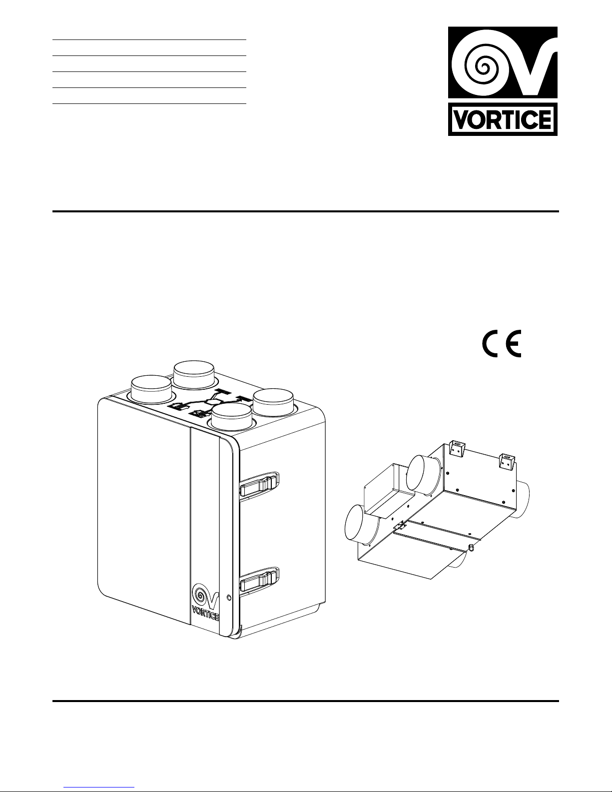
• Specifications for the power supply must correspond to
the electrical data on ID plate A (Fig. 1).
• The appliance must be installed by a
professionally qualified technician.
• The appliance must be wired to the power
supply by way of a multi-pole isolating switch
with a gap of at least 3 mm between contacts.
Items supplied
The main parts of the appliance are:
• an outer casing made using an expanded polypropylene shell and a
hinged hatch (removable);
• a cross and counter flow heat exchanger, made of polystyrene, featuring
a special geometry designed to guarantee ultra high efficiency in terms of
heat exchange (>85%);
• two energy-saving variable speed brushless motors (2 preset speeds);
• electronic circuits supervising the power input, monitoring and control of
the appliance;
• temperature sensors (bypass and defrost);
• remote controller (wall installation);
• two G3 filters (UK), M5 filters (NOT UK); (option of F5 or F7 filter);
• wall-mounting bracket (optional).
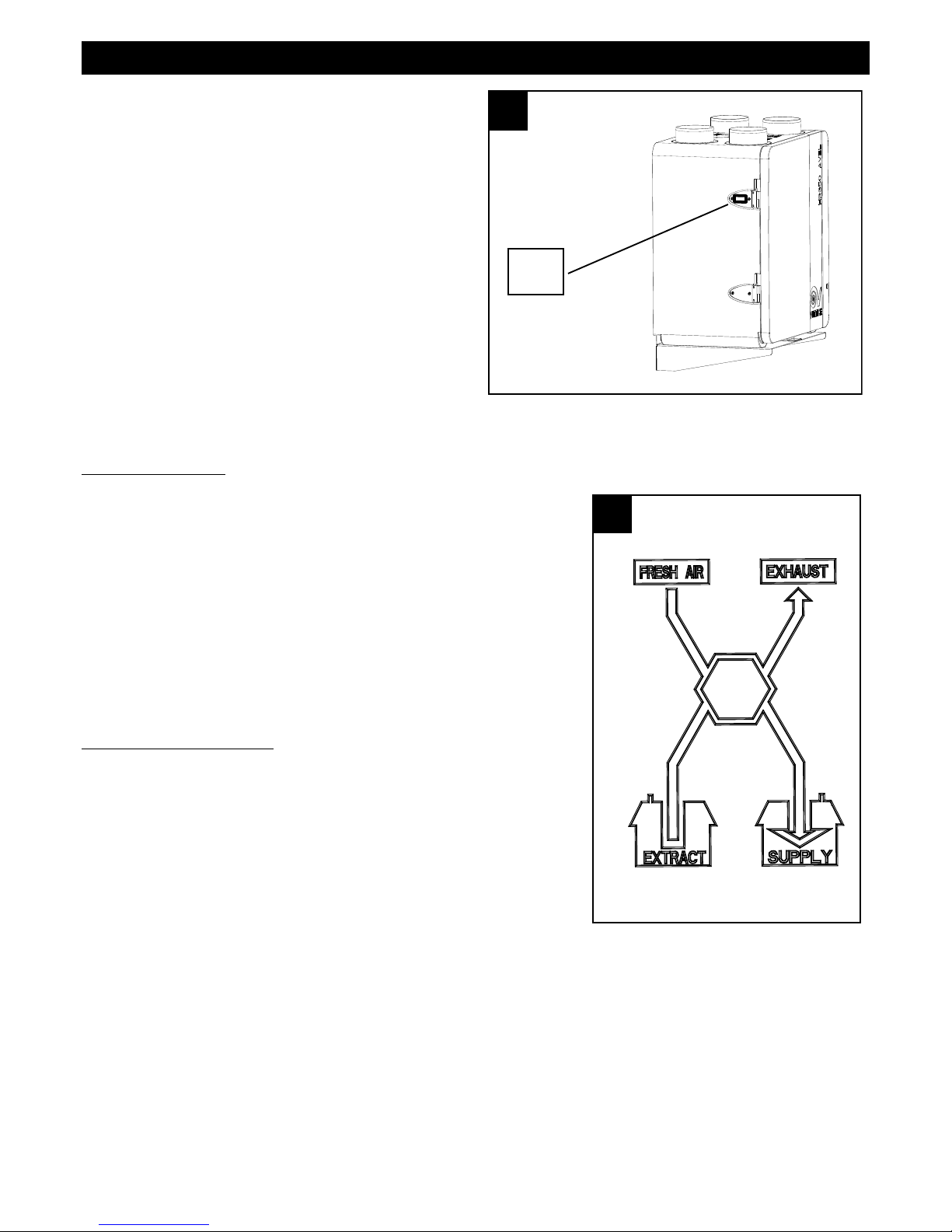
Key to air connections (Fig.2)
A: Fresh air intake from outside
B: Stale air intake from room
C: Clean air outlet inside the room
D: Stale air outlet to outside
ENGLISH
1 1
A
2 2
A D
B C
Page 5
17
Installation
N.B. The appliance is not suitable for outdoor installation. The appliance must be installed in accordance with current
safety regulations in the destination country, and with the instructions in this booklet. The appliance must be installed on
an internal surface or wall of the home structurally suited to holding its weight (max. 30 kg). The appliance cannot be
positioned and secured in place using only adhesives. The connection of the ventilation ducts to the appliance must be
made with the aid of a tool.
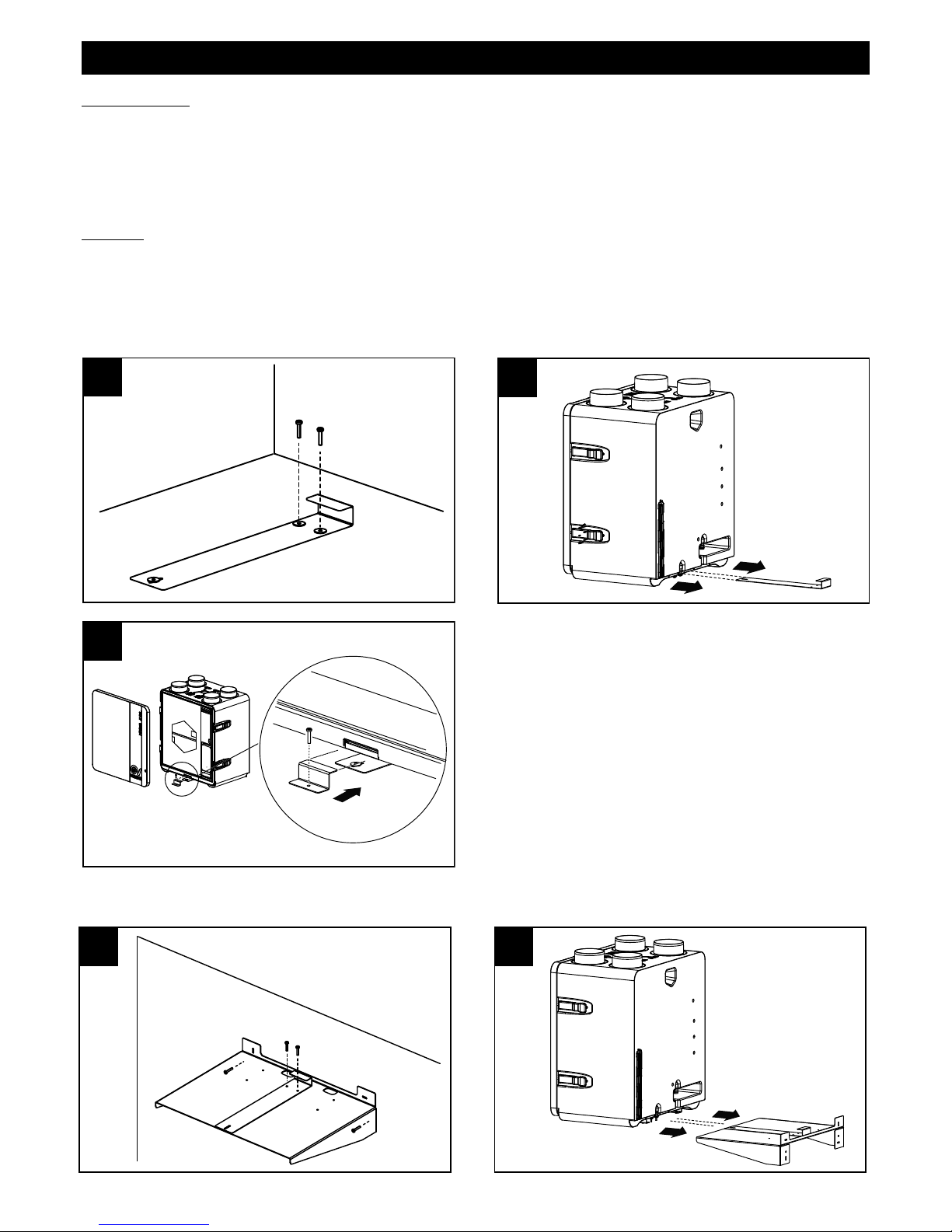
Mounting
The appliance can be floor-standing or wall-mounted.
Floor
N.B. if opting for floor-standing installation, leave enough room underneath the appliance to create the siphon traps on
the condensate drain outlets (see also Condensate Drain paragraph). The appliance can be placed or secured using the
fixing systems supplied by Vortice (optional) (Vortice recommended method) (see figure sequence 3, 4, 5).
Wall
We recommend using the bracket supplied by Vortice (optional) (Fig.6, 7, 8).
ENGLISH
3 3
4 4
5 5
6 6
7 7
Page 6
18
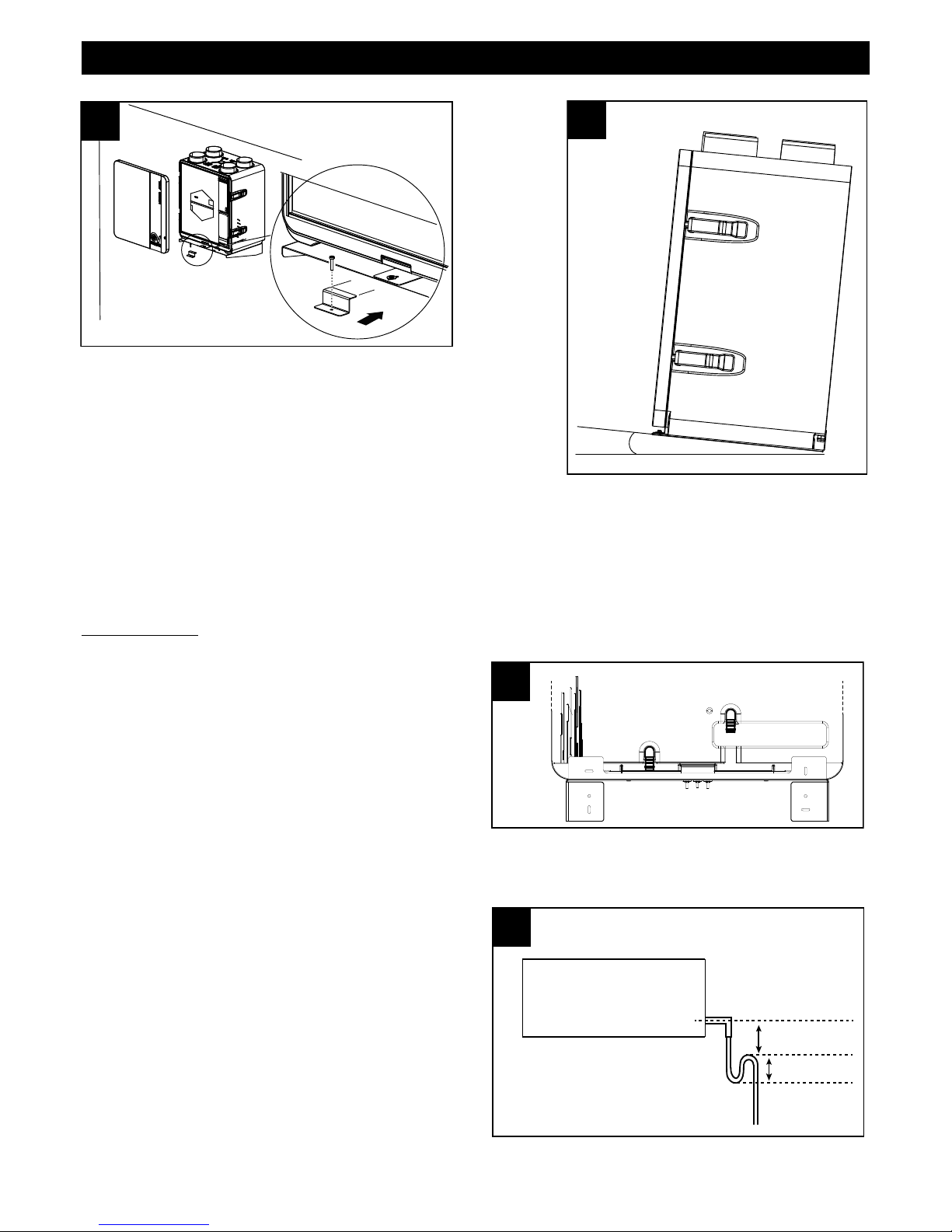
Make sure that the appliance is level in order to ensure faultless
operation. It is acceptable for the appliance to be tilted no more than a
few degrees to the rear (fig.9).
The ducts used for conveying air must be of the correct size. The ducts to and from the outdoors must be thermally
insulated and not subject to vibration. The 150 mm standard diameter inlet and outlet ducts must be secured to the
corresponding ports of the appliance by means of clips or other suitable fastening systems. If stale air is exhausted via
the roof, the outlet must be designed so as to prevent the formation of condensate and the entry of rain water. If fresh air
enters via the roof, the intake must be designed so as to prevent the formation of condensate and the entry of rain water.
Condensate drain
During normal operation, condensate collects at the bottom of the appliance in a double tray provided with two drain
outlets. The connection points are located at the back of the
appliance, towards the bottom. The condensate drain can
be provided by connecting the drain outlets to two flexible
hoses with an internal diameter of 19 mm approx. A siphon
trap should be created to prevent air bubbles from forming.
Important instructions: winter operation: high probability of
condensate forming; drain hoses must be connected, with a
siphon trap. (Fig.10a) summer operation: probability of
condensate forming; drain hoses should be connected, with
a siphon trap. (Fig.10b)
Cut the end of the hose obliquely
N.B. The siphon must be created observing the dimensions
indicated in fig. 11, otherwise correct operation of the
appliance cannot be guaranteed. Condensate can also be
drained off through the waste plumbing system of the
building.
ENGLISH
8 8
9 9
α
0≤α<2°
a
b
h > 50 mm∆
≥ 60 mm
Page 7
19
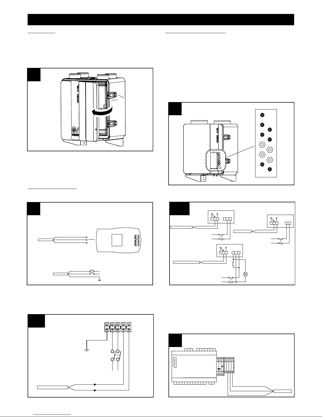
Electrical connections
User control panel/power supply Accessories
Connection to Heater
ENGLISH
12 12
13 13
1
2
3
4
5
6
7
8
9
10
11
14 14
INSTALLER/USER CONTROL PANEL
PANNELLO INSTALLATORE/UTENTE
black/ GND
blue / signal
brown / +12V dc
SKW 22
Marrone / Brown (+12V dc)
Nero / Black (GND)
Blu / Blue (segnale / signal)
POWER SUPPLY
ALIMENTAZIONE
L
N
Marrone / Brown
Blu / Blue
Giallo-Verde / Yellow-Green
14b 14b
PRE-HEATER
N1L1
LN
tt
marrone / brown
blu / blue
Da HR 350 AVEL
From HR 350 AVEL
CAVO PREHEATER
Accessibility
The appliance can be accessed easily via the front hatch
(Fig.12) for servicing/maintenance purposes, including
air filter removal and replacement procedures. (See also
"Maintenance/Cleaning" paragraph)
Junction box inputs (fig.13)
1: Temperature
2: Bypass open
3: Supply power
4: Bypass close
5: Supply signal
6: Preheater
7: Boost
8: Power Supply
9: Display
10: Exhaust power
11: Exhaust signal
From AVEL
Dall'unità AVEL
nero-black
blu-blue
marrone-brown
RD
L1N1BL
N2
PLC
HA
Supply Supply
TTL
BK
DI1 DI2
AO3AO4 AO5 12V
AI1
AI2 AI3 AI4 AI 5GND
DO1DO2DO3
6
LAN
BL
RD BK
14 a14 a
321 TMNL
L
N
CAVO BOOSTER
Nero / Black
Rosso / Red
C TIMER cod.12999
C TEMP cod.12992
C SMOKE cod.12993
C PIR cod.12998
C HCS cod.12994
321
L
N
LN
N
L
321 TMLN
CAVO BOOSTER
Nero / Black
Rosso / Red
Rosso / Red
CAVO BOOSTER
Nero / Black
Connection to VORT HAif the Avel appliance is equipped
with an HA unit, the heat recovery unit must be connected to
this unit by way of the brown/blue/black three core cable
coming from the unit, as in fig.15. In this case, accordingly,
the display will no longer be connected to the heat recovery
unit but to the brown/blue/black three core cable on the
VORT HA, as indicated in the VORT HA manual.
Page 8
20
Use
When the appliance is switched on and has been running for 2 minutes, both motors will stop to allow repositioning of
the by-pass valve. The motors will start up again after approximately 1 minutes.
N.B.: this is a normal system procedure and should not be perceived as a malfunction.
The appliance is rated for continuous duty.
The appliance is wired to a special dedicated control panel, the functions of which are described further on. This model
can be used in combination with a Vortice preheater, which must be fitted and set up by the installer. The minimum
distance of the preheater from the appliance is 500 mm.
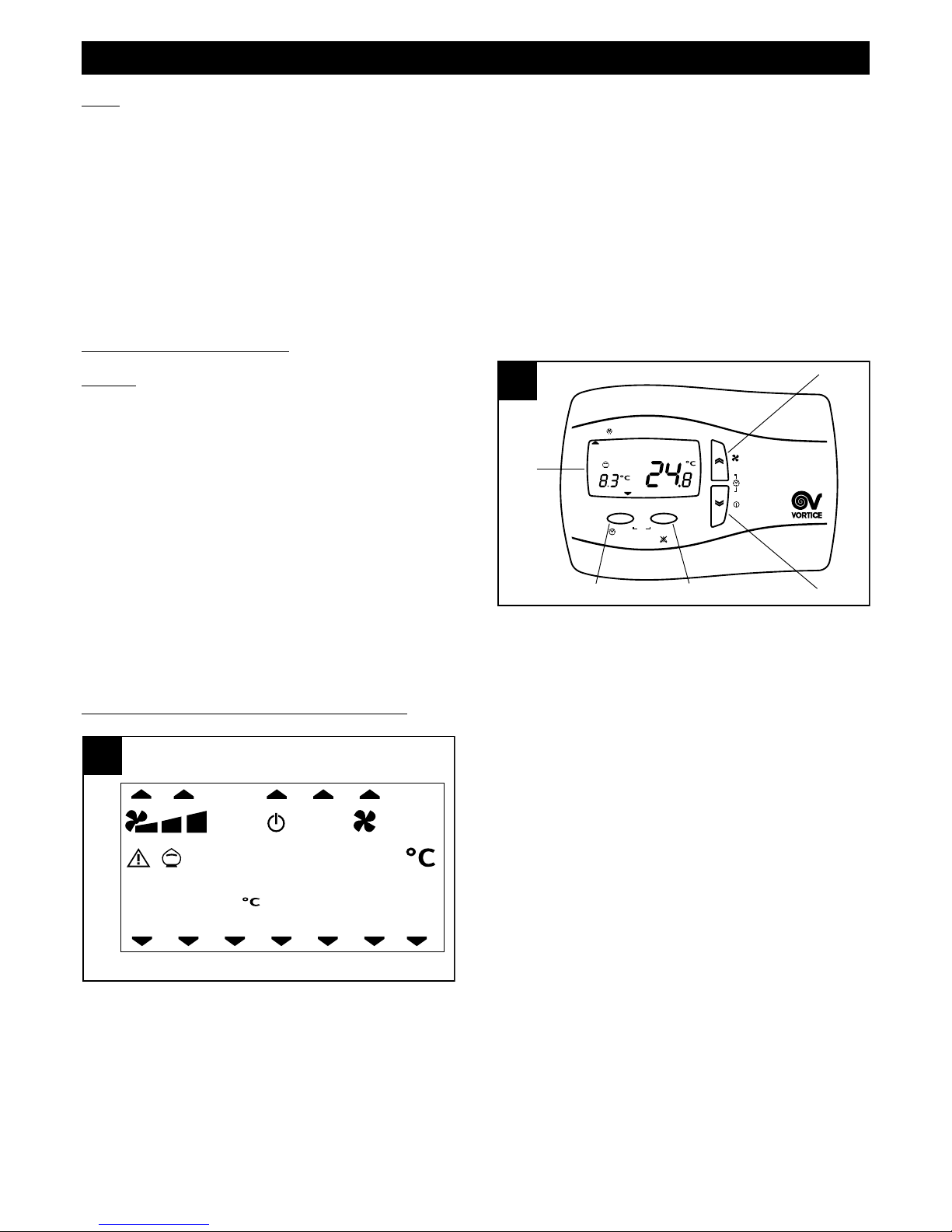
User panel Functions
General (fig.16)
A = “UP” button: list up
B = “DOWN” button: list down
C = SET button: acquire data
D = ESC button: exit
E = display
A panel allows the user to control the operating parameters
of the appliance:
- on/off (NO UK)
- current time/day (NO UK or models with HA)
- operating speed
- required room temperature
- selection of bypass function
- “HA” operation mode (for models provided with HA module)
The function of the ESC button, unless otherwise stated, is always that of quitting without saving data.
Summary of icons displayed on the panel (Fig.17)
11. P2 time profile: see “User Menu” section (NO UK or models with HA)
12. HA: (only models with HA)
14. actual operating speed: the icons light up permanently to indicate which of the 3 speeds is currently selected.
15. system stand-by status: the icon lights up permanently to indicate that the appliance is in stand-by (powered up but
with the motors off), due to the activation of an alarm (UK), or because the system is shut down (NO UK); the icon
blinks (NO UK) to indicate that the appliance is in stand-by after programming time bands (see section on
“Programming of time profiles”);
16. the icon lights up to indicate that an alarm has been tripped; when the icon blinks, this indicates that an alarm with
manual reset has been tripped (see “View alarms menu”)
17. bypass function: the icon indicates: (see also "Activation of bypass function" paragraph)
ENGLISH
esc set
16 16
B
y-Pass
/ °C
1
2345
6
7
P1 P2
Prg
A
B
C
D
E
FILT
HA
17 17
8 9 10 11 12
14
15
16 17 19
1 2 3 4 5 6 7
20
21
1÷7day of the week (NO UK markets or models with HA):
1=Monday, 2=Tuesday, etc.
8. filter alarm: this icon lights up to warn that the filters
should be replaced within three months; if the filters are
not renewed by the end of this period, the system will
lock up and the filter error message FILT appears (see
"View alarm menu")
9. no-frost function: the icon lights up permanently when
the no-frost procedure is active; the icon will flash to
indicate a “no-frost timeout”: in this instance the no-frost
procedure has proved insufficient and the appliance
goes into protected mode for one hour, with the motors
off, following which it will restart automatically.
10. P1 time profile: see “User Menu” section (NO UK or
models with HA)
Page 9

21
off: bypass deactivated
permanently alight: bypass opened manually
blinking: bypass opened automatically via software (in this case the bypass cannot be closed manually)
19. indoor temperature, degrees Celsius
20. view outdoor temperature, degrees Celsius
21. Boost active
On/off (NO UK) (fig.18
The appliance is switched on and off by pressing and holding
the "down" button on the panel.
Set time/day (NO UK or models with HA) (fig.19)
Select speed (fig.20)
Before proceeding with the steps indicated below, press the
ESC button to exit and return to the initial menu. The
operating speed is preset during appliance configuration,
and can be selected by pressing the UP button briefly
(1=min. speed, 2=med. speed, 3=max. speed).
ENGLISH
esc set
By-Pass
/ ° C
1234567
FILT
P1 P2
Prg
20 20
HA
esc set
By-Pass
/ ° C
1234567
FILT
P1 P2
Prg
HA
Before proceeding with the steps indicated below, press the
ESC button to quit and return to the initial menu.
The current time and day can be set as follows:
- press the “up” and “down” buttons together briefly
- press the “up” or “down” button repeatedly to select the
"hours” setting (HH);
- press the SET button briefly to retain the “hours” setting and
move on to the “minutes” setting (MM);
- press the “up” or “down” button repeatedly to select the
"minutes”;
- press the SET button briefly to retain the “minutes” setting
and move on to the “day” setting (dAy);
- press the “up” or “down” button repeatedly to select the
"day” setting;
- press the SET button briefly to retain the “day” setting and
quit.
esc set
By-Pass
/ ° C
1234567
FILT
P1 P2
Prg
HA
Page 10

22
Set required room temperature (fig.21)
Before proceeding with the steps indicated below, press the
ESC button to exit and return to the initial menu. The
preferred room temperature can be selected as follows:
- press and hold the SET button
- press the SET button briefly (the current value flashes)
- select the required value using the UP and DOWN buttons
- press the SET button briefly to retain the setting
- press the ESC button briefly to exit.
Activate “bypass” function (fig.22)
The purpose of the bypass function is to ventilate the
apartment without heat transfer. With the bypass valve open,
air can be introduced directly from outside, without passing
through the heat exchanger. The flow of air vented from
inside continues to pass through the heat exchanger. Before
proceeding with the steps indicated below, press the ESC
button to exit and return to the initial menu. The “bypass”
function can be forced by pressing and holding the ESC
button. The corresponding "money box" icon will light up (the
function remains active for 12 hours, after which the
appliance will revert to automatic operation)
ENGLISH
esc set
By-Pass
/ ° C
1234567
FILT
P1 P2
Prg
21 21
HA
esc set
By-Pass
/ ° C
12345
6
7
FILT
P1 P2
Prg
22 22
HA
esc set
By-Pass
/ ° C
1234567
FILT
P1 P2
Prg
23 23
HA
View time/outdoor temperature display (NO UK or models with HA) (fig.23)
Before proceeding with the steps indicated below, press the
ESC button to quit and return to the initial menu.
The current values of the "time" and "outdoor temperature"
parameters can be viewed in alternation by pressing the ESC
button briefly.
Page 11

23
User Menu
Before proceeding with the steps indicated below, press
ESC to exit and return to the opening screen. As a rule, the
parameters relative to the various options are selected by
pressing SET (this causes the current value to blink), then
scrolling through the available values with the UP and DOWN
buttons, and pressing SET again to confirm the new value.
The UP and DOWN buttons are also used to scroll through
the different options or parameters. The main user menu can
be viewed by pressing and holding ESC and SET at one and
the same time. The options of the menu are:
- PROF (NO UK only): settings for operation with time
profiles:
P1, used to program one period of operation per day, with
a start time, an end time and a fan speed;
P2, used to program two periods of operation per day, each with a start time, an end time and a fan speed.
The user can allocate a different profile to each day of the week.
- HA: settings in HA operating mode: available only on appliances with HA module;
- SERV: service (option available only to the installer).
Option PROF (NO UK)
Selecting PROF by pressing SET, the settings for time profiles
are accessed. The parameters are:
- En (Enable): possible values are:
ON: enables operation with profiles (and as noted above,
automatically disables any possibility of operation in HA
mode)
OFF: disables operation with profiles.
If EN ON has been selected, the following parameters are also
enabled:
- ST: start time, profile P1 interval
- END: end time, profile P1 interval
- ST1: start time, profile P2 interval 1
- EN1: end time, profile P2 interval 1
- ST1: start time, profile P2 interval 2
- EN1: end time, profile P2 interval 2
- MON: allocation of profile to Monday: possible values are P1 and P2
- TUE: allocation of profile to Tuesday: possible values are P1 and P2
- WED: allocation of profile to Wednesday: possible values are P1 and P2
- THU: allocation of profile to Thursday: possible values are P1 and P2
- FRI: allocation of profile to Friday: possible values are P1 and P2
- SAT: allocation of profile to Saturday: possible values are P1 and P2
- SUN: allocation of profile to Sunday: possible values are P1 and P2
ENGLISH
esc set
By-Pass
/ ° C
1234567
F
ILT
P2
Prg
24 24
P1
HA
esc set
By-Pass
/ ° C
12345
6
7
FILT
P2
Prg
25 25
P1
HA
Page 12

Option HA
This option is available only on models with HA module
Selecting HA by pressing SET, the settings for HA operating
mode are accessed. The parameters are:
- En (Enable): possible values are:
PROF: enables HA mode with profiles
ON: enables HA mode continuously
OFF: disables HA mode
HOL: enables HOLIDAY mode: two hours antibacterial
operation per day, two hours refresh, 20 hours stand-by.
If EN PROF has been selected, the following parameters
are also enabled:
- ST: start time, profile P1 interval
- END: end time, profile P1 interval
- ST1: start time, profile P2 interval 1
- EN1: end time, profile P2 interval 1
- ST2: start time, profile P2 interval 2
- EN2: end time, profile P2 interval 2
- MON: allocation of profile to Monday: possible values are P1 and P2
- TUE: allocation of profile to Tuesday: possible values are P1 and P2
- WED: allocation of profile to Wednesday: possible values are P1 and P2
- THU: allocation of profile to Thursday: possible values are P1 and P2
- FRI: allocation of profile to Friday: possible values are P1 and P2
- SAT: allocation of profile to Saturday: possible values are P1 and P2
- SUN: allocation of profile to Sunday: possible values are P1 and P2
View alarm menu (fig.27)
Before proceeding with the steps indicated below, press the
ESC button to exit and return to the initial menu. The
indication of any alarm conditions that may have been
tripped can be displayed as follows:
--press and hold the SET button
--press and release the UP or DOWN button to view the
ALRM menu
--press and release the SET button to view the active error
code The various alarm situations that can affect the system
are displayed on the user panel as follows:
ti: indoor temperature sensor faulty; contact Technical
Support for assistance;
tout:: outdoor temperature sensor faulty; contact Technical
Support for assistance;
te: exhaust air temperature sensor faulty; contact Technical
Support for assistance;
preh: preheater faulty or missing (if applicable); contact Technical Support for assistance;
Hito: outdoor temperature higher than 45 °C; contact Technical Support for assistance;
Hiti: indoor temperature higher than 45 °C; contact Technical Support for assistance;
Filt: clogged filters need replacing (3 months). Once new filters have been fitted, the error can be reset by the user: this
is done simply by pressing and holding the UP and DOWN buttons together.
N.B. Manually resettable errors can be removed by pressing and holding the UP and DOWN buttons together.
24
ENGLISH
esc set
By-Pass
/ ° C
1234567
FILT
P2
Prg
26 26
P
1
HA
Page 13

25
Maintenance and cleaning
Before commencing any servicing operation, make sure that
the appliance is disconnected from the electrical power
supply. Dismantling and assembly are special maintenance
operations and must be entrusted to professional
technicians.
N.B. Before opening the hatch, loosen the front safety screw.
(fig.28)
Filters
Recommended maintenance intervals: Because levels of air
pollution depend typically on geographical location and are
variable, the life of the filters will be similarly variable. With
this general consideration in mind, the following filter
maintenance intervals are recommended:
Inspect filters: every 50/60 days;
replacement of filters: after 3 or 12 months (UK), 3 or 24 months (NO UK) (depending on the value set by the installer) a
pre-alarm message will appear on the display to remind the user of the need for the filters to be replaced. The filters must
be replaced within 3 months (UK), 2 months (NO UK) after this message appears, otherwise the appliance will shut down
at the end of the 3 months, activating the filters clogged alarm (Filt). When the error is reset (as described in "View alarm
menu" paragraph), the counter will also be reset.
N.B. Failure to clean or replace filters can seriously affect system efficiency, causing:
- increased pressure losses in the air circulation system and reduced airflow;
- drop in system performance and comfort levels caused by pressure losses.
N.B. Clogged air filters are the most frequent cause of the appliance locking up: (Filt)
Removal of filters: fig.29
ENGLISH
28 28
28
29 29
Page 14

26
Important information concerning the environmentally compatible disposal
IN CERTAIN EUROPEAN UNION COUNTRIES THIS PRODUCT DOES NOT FALL WITHIN THE REQUIREMENTS OF
THE NATIONAL LAWS IMPLEMENTING DIRECTIVE WEEE, AND IN THESE COUNTRIES THE PRODUCT IS NOT
SUBJECT TO SEPARATE DISPOSAL OPERATIONS AT THE END OF ITS WORKING LIFE.
This product conforms to EU Directive2002/96/EC.
This appliance bears the symbol of the barred waste bin. This indicates that, at the end of its useful life, it
must not be disposed of as domestic waste, but must be taken to a collection centre for waste electrical
and electronic equipment, or returned to a retailer on purchase of a replacement.
It is the user's responsibility to dispose of this appliance through the appropriate channels at the end of its
useful life. Failure to do so may incur the penalties established by laws governing waste disposal.
Proper differential collection, and the subsequent recycling, processing and environmentally compatible disposal of waste
equipment avoids unnecessary damage to the environment and possible related healthrisks, and also promotes recycling
of the materials used in the appliance.
For further information on waste collection and disposal, contact your local waste disposal service, or the shop from
which you purchased the appliance.
Manufacturers and importers fulfil their responsibilities for recycling, processing and environmentally compatible disposal
either directly or by participating in collective systems.
ENGLISH
Page 15

A
TAGLIANDO INTERVENTO IN GARANZIA
CERTIFICATE OF WORK PERFORMED UNDER GUARANTEE
COUPON INTERVENTION SOUS GARANTIE
DATA INT E RVE N TO
DATE OF WORK - DATE INTERVENTION
TIMBRO CENTRO ASSISTENZA
STAMP OF TECHNICAL ASSISTANCE CENTRE - CACHET SERVICE APRES-VENTE
TAGL I AND O IN T ER V E NTO IN G ARA N ZIA
CERTIFICATE OF WORK PERFORMED UNDER GUARANTEE
COUPON INTERVENTION SOUS GARANTIE
DATA INTERVENTO
DATE OF WORK - DATE INTERVENTION
TIMBRO CENTRO ASSISTENZA
STAMP OF TECHNICAL ASSISTANCE CENTRE - CACHET SERVICE APRES-VENTE
TAGL I AND O IN T ER V E NTO IN G ARA N ZIA
CERTIFICATE OF WORK PERFORMED UNDER GUARANTEE
COUPON INTERVENTION SOUS GARANTIE
DATA INTERVENTO
DATE OF WORK - DATE INTERVENTION
TIMBRO CENTRO ASSISTENZA
STAMP OF TECHNICAL ASSISTANCE CENTRE - CACHET SERVICE APRES-VENTE
TAGL I AND O IN T ER V E NTO IN G ARA N ZIA
CERTIFICATE OF WORK PERFORMED UNDER GUARANTEE
COUPON INTERVENTION SOUS GARANTIE
DATA INTERVENTO
DATE OF WORK - DATE INTERVENTION
TIMBRO CENTRO ASSISTENZA
STAMP OF TECHNICAL ASSISTANCE CENTRE - CACHET SERVICE APRES-VENTE
B
C
D
Page 16

ITALIA
Spedire la garanzia in busta
chiusa a:
Vortice Elettrosociali S.p.A.
Strada Cerca 2
Frazione di Zoate
20067 Tr i b i a n o Milano
OTHER COUNTRIES
Please send the guarantee to
the retailer’s ad dr e ss i n the
country where the appliance
has been purchased.
Autorizzo la Vortice
Elettrosociali S.p.A.
adinserire i miei dati
nelle sue liste e a
comunicarli a terzi
per l’invio di materiale
pubblicitario ed
informativo. In ogni
momento,anorma
dell’art. 13legge
675/96, potròavere
accesso ai miei dati,
chiederne la modi
ca
olacancellazione
oppure oppormi al
loro utilizzo scrivendo
aVortice
Elettrosociali S.p.A.
Responsabile
trattamento dati -
Strada Cerca, 2 Frazione di Zoate 20067 Tribiano (MI).
Non autorizzo
(barrare se interessa).
Idonotauthorize
(please tickif
required).
IauthorizeVortice
Elettrosociali S.p.A.
and its local
distributors to include
my personal details
within their database
and they can use it
through a third party
for the despatch of
advertising material.
At any time, in
accordance with the
regulations in force
within my country. I
can have access to
details and can ask to
make changes, or
prohibit the usage of
my details.This will be
done by addressing
my request directly to
the headquarters of
the local distributor
where the appliance
has been bought.
UK-IRELAND
Send the guarantee
in sealed envelope to:
Vorti ce Limited
Beeches House
Eastern Avenue
Burton on Trent
DE13 0BB United Kingdom
IauthorizeVortice
Ltd. to include my
personal details
within their database,
which they use, via a
third party for the
despatch of
advertising material,
at any time, in
accordance
with the regulations in
force within my
country.
Icanhaveaccess
to my details and can
request changes, or
prohibit the usage of
my details.This will be
done by addressing
my request directly to
Vorti ce Li mi ted
Beeches House
Eastern Avenue
Burton on Trent
DE13 0BB United
Kingdom.
Idonotauthorize
(please tick if
required).
FRANCE
Expédier la garantie sous
enveloppe cachetée a:
Vorti ce France
15-33, Rue Le Corbusier Europarc - CS 30007
90046 CRETEIL CEDEX
Conformément àla
loi informatique et
liberté art. 27 du
27/01/78, vous
disposez d’un droit
d’accés et de
recti
cation des
donné es vous
concernant auprès de
Vorti ce Fr an ce - 72,
Rue Baratte - Cholet94106 Saint Maur
Cedex.
Par notre
intermédiaire,
votre adresse pourra
être transmise à
des tiers.
Sauf opposition de
votre part (auquel cas
cochez la case ci
dessus).
IT ALIA
CONDIZIONI DI GARANZIA
VORTICE SPA garantisce i suoi prodotti per
24 mesi dalla data dell’acquisto che deve
essere comprovata da idoneo documento
scale (scontrino o fattura) rilasciato dal
venditore. Nel suddetto periodo di garanzia
VORTICE SPA si
impegna, dopo aver effettuato le opportune
valutazioni tecniche, a riparare o a
sostituire, gratuitamente, le parti
dell’apparecchio che risultassero affette da
difetti di fabbricazione. La presente
garanzia, da attivare nei modi e nei termini
d
iseguitoindicati,lasciaimpregiudicatii
diritti derivanti al consumatore dalla
applicazione del D. lgs. 24/2002.Tali diritti,
conformemente alla legge, potranno essere
fatti valere esclusivamente nei confronti del
proprio venditore. La presente garanzia è
valida su tutto il territorio italiano.
Modalità e condizioni di attivazione della
garanzia
Gli interventi in garanzia (riparazioni o
sostituzioni del prodotto ovvero delle parti
difettose) saranno eseguiti presso uno dei
Centri di Assistenza Tecnica autorizzati da
VORTICE il cui indirizzo è disponibile
sull’elenco telefonico alfabetico o
contattando il numero verde 800.555.777.
La prestazione eseguita in garanzia non
prolunga il periodo della garanzia. Pertanto,
incaso di sostituzione del prodotto o di un
suo componente, sul bene o sul singolo
componente fornito in sostituzione non
decorre un nuovo periodo di garanzia ma si
deve tener conto della data di acquisto del
prodotto originario.
UK AND IRELAND
CONDITIONS OF WAR-
RANTY
This guarantee is offered as an extra
bene
tanddoesnotaffectyourlegal
r
ights. All electrical appliances produced
by Vortice are guaranteed by the
Company for two years against faulty
material or workmanship.
If any part is found to be defective in this
w
ay within the
r
st twenty months four
from the date of purchase or hire
purchase agreement, we or our
authorised service agents, will replace or
at our option repair that part without any
charge for materials or labour or
transportation, provided that the
appliance has been used only in
a
ccordance with the instructions
provided with each appliance and has
been not connected to an unsuitable
electricity supply, or subjected to misuse,
n
eglect or damage or modi
e
dor
repaired by any person not authorised by
us.The correct electricity supply voltage
is shown on the rating plate attached to
the appliance.
This guarantee is normally available only
to the original purchaser of the appliance,
but the Company will consider written
applications for transfer.
Should any defect arise in any Vortice
product anda claim under guarantee
become necessary, the appliance should
be carefully packed and returned to your
approved Vortice stockist.This portion of
the guarantee should be attached to the
appliance.
FRANCE
CONDITIONS DE GARANTIE
Votre a ppareil e st co uvert par n ot re garan ti e à
condition qu’il ne soit pas utilisé à des
ns autres
que celles dé
nies dans nos ches techniques.
Il est garanti pendant deux ans pour l’ensemble
des pièces qui le compose, contre tout vice de
fabrication ou défaut de matiére,
et ce, dès la date de la première mise en service
Cette garantie s’applique au remplacement gratuit
o
uàlaréparationsansfraisdespiècesreconnues
défectueuses par nos services;ellenepeut,en
a
ucun cas, donner lieu à des dommages et
intèréts.
Les frais de transport restant à la charge de
l’utilisateur, et le material voyage à ses risques et
perils.
La garantie sera sans eff et si:
•L’appareilasubiundémontage,un
remplacement, de piéce ou une réparation hors
de nos ateliers.
•S’ilaétésurvolté.
•
S’il a été utilisé dans une atmosphére
corrosive.
•S’ilaétédeterioréoubriséparaccident(choc
ou chute....) ou même pendant le transport (le
transporteur est seul responsable).
•Lagarantienes’appliquepassurlespiecesà
durée de vie limitée, (
ltre charbon, charbon
pour collecteur etc....)
En cas de panne. N’écrivez pas, mais retournez
directement l’appareil soigneusement emballé à
notre service après vente voir coordonnées sur
www.vortice-france.com ou au 01.55.1250.00.
Joindre à l’envoi: le présent certi
cat de garantie
validé par le vendeur, accompagné d’une note
explicative succinte.
Page 17

ANNI
YEARS
2
ANNI
YEARS
2
DATI UTENTE / CUSTOMER DATA / COORDONNÉES DE L’UTILISATEUR
nome /name/nom______________________________________________
cognome /surname/prenom_________________________________
via /street/rue __________________________________________________
cap /postcode/codepostal _____________________________________
città /town______________________________________________________
TIMBRO RIVENDITORE
stamp of supplier
cacher du vendeur
2
GARANZIA - GUARANTEE - GARANTIE
DA SPEDIRE
(entro 8 giorni dall’acquisto)
TO SEND (within 8 days from date of purchase)
ARETOURNER(dansles8joursaprèsl’achat)
Per poter usufruire della garanzia il cliente deve compilare e rispedire alla VORTICE
SPA, entro 8 giorni dall’acquisto, la “Parte 2”deltagliandodigaranzia,all’indirizzo
econlemodalitàintaleparteriportate.
La “Parte 1”deltagliandodigaranziadeveessereconservataepresentata,
unitamente al documento
scale (scontrino o fattura) rilasciato dal venditore al
momento dell’acquisto, al Centro di Assistenza autorizzato VORTICE che dovrà
eseguire l’intervento in garanzia.
This warranty must be attached to the appliance should it need to be returned for
servicing.
N.B. Guarantee is only valid if all details are completed correctly.
ATT E N T ION : po u r b éné
cier de la garantie, le présent certi cat doit obligatoirement
accompagner l’appareil présumé défectueux. Le certi
cat doit porter le cachet du
revendeur et la date d’achat.
Adefaut,lagarantieseracomptéeàpartirdeladatedesortied’usine.
GARANZIA - GUARANTEE - GARANTIE
DA CONSERVARE
TO BE RETAINED
ACONSERVER
Esclusioni
L
apresentegaranzianoncopre:
•Lerottureprovocatedaltrasporto.
•Idifettioguastiderivantidausononcorrettooimpropriodapartedelcliente.
•
Idifettiderivantidalmancatorispettodelleavvertenzeecondizionid’uso
indicate nel libretto di istruzioni ed uso allegato al prodotto.
•Idifettiderivantidanoncorrettainstallazioneovverodaunainstallazione
effettuata senza rispettare quanto previsto nel relativo capitolo del libretto di
istruzioni ed uso.
•Iguastiderivantidaunerratoallacciamentoallaretedialimentazioneelettricaopertensionedialimentazionediversadaquellaprevistaper
l’apparecchio, ovvero diversa dal limite stabilito dalle norme CEI (+/- 10% del valore nominale).
La presente garanzia non copre, inoltre, gli eventuali difetti derivanti da una cattiva manutenzione ovvero da interventi effettuati da personale non
quali
cato o da terzi non autorizzati.
1
Dichiaro di aver preso atto delle condizioni di garanzia speci cate sul certi cato in mio possesso e autorizzo la gestione dei miei dati personali (v. retro).
IhavereadandunderstoodthetermsandconditionsofthisguaranteeandIauthorisetheprocessingofmypersonaldetails(seeoverleaf).
Suivant les conditions de garantie dé
nies par le certi cat en ma possession j’autorise l’utilisation de mes coordonnées (voir au verso).
rma / signature / signature _________________________________
DATA
DATA - DATE
ANNI
YEARS
2
ANNI
YEARS
2
SPEDITO IL
MAILING DA TE - ENVOYÉ PAR LA POSTE LE
CONF.
----------------COLL.
TIMBRO RIVENDITORE
stamp of supplier
cacher du vendeur
SPEDITO IL
MAILING DATE - ENVOYÉ PAR LA POSTE LE
ACQUISTATO IL
DA TE OF PURCHESE - DA TE DE L’ACHAT
DATA
DATA - DATE
68
Page 18

PANNELLO SISTEMI HR
Istruzioni per l’installatore
Instructions for the installer
esc set
By-Pass
/ ° C
1234567
P1 P2
Prg
FILT
HA
VORTICE LIMITED
Beeches House - Eastern Avenue
Burton on Trent
DE13 0BB
Tel. (+44) 1283-492949
Fax (+44) 1283-544121
UNITED KINGDOM
VORTICE ELETTROSOCIALI S.p.A.
Strada Cerca, 2 - frazione di Zoate
20067 TRIBIANO (MI)
Tel. (+39) 02-90.69.91
Fax (+39) 02-90.64.625
ITALIA
COD. 5.471.084.196
05/05/2015
VORTICE FRANCE
15-33, Rue Le Corbusier Europarc
CS 30007
90046 CRETEIL CEDEX
FRANCE
Page 19

9
Setting operating parameters
During initial configuration of the appliance, the installer must proceed as described below, using a dedicated menu on
the control panel to set the following parameters governing the operation of the machine.
Before proceeding with the steps indicated below, press ESC to exit and return to the opening screen.
As a rule, the parameters relative to the various options can be selected by pressing SET (this causes the current value
to blink), then scrolling through the available values with the UP and DOWN buttons, and pressing SET again to confirm
the new value. The UP and DOWN buttons are also used to scroll through the different options or parameters.
The main user menu can be viewed by pressing and holding ESC and SET at one
and the same time (fig.1).
In this menu, the SERV option is for the use of installers only. Select SERV,
entering a password to allow access (default factory setting: “1”). The SERV
menu presents the following options:
- FrSt:
- temp:
- Filt:
- FAnE:
- FAn:
- rE:
- MbUS:
- HASE:
Each option brings up a corresponding sub-menu, as illustrated in detail below:
Menu “FrSt” (Nofrost)
This menu allows the user to enable/disable the no-frost strategy. The menu presents 3 parameters:
Menu “temp” (Temperatures)
This menu allows the user to read the temperatures detected by the heat recovery unit. The menu presents 3 parameters:
ENGLISH
management of Nofrost procedures
indication of temperatures (read only)
filter management
control of return air fan motor speed
control of supply air motor speed
firmware revision (read only)
selection of modbus connection parameters
control of motor speed in HA mode
esc set
By-Pass
/ °C
1234567
FILT
P2
Prg
1 1
P1
H
A
esc set
By-Pass
/ °C
12345
6
7
FILT
P2
Prg
P1
HA
4 4
esc set
By-Pass
/ °C
12345
6
7
FILT
P
2
Prg
P1
HA
3 3
esc set
By-Pass
/ °C
1234567
FILT
P2
Prg
P1
HA
2 2
• “UnbL” (Fig.2). Nofrost via flow
unbalancing. Possible values are:
ON: no-frost function enabled;
OFF: no-frost function disabled;
• “HEAt”(Fig.3). Possible values are:
ON: preheater enabled
OFF: preheater disabled
• “HA”(Fig.4). Available only in systems
with HA. Nofrost via recirculation.
Possible values are:
ON: HA enabled
OFF: HA disabled
esc set
By-Pass
/ °C
1234567
FILT
P2
Prg
P1
HA
°C
77
esc set
By-Pass
/ °C
1234567
FILT
P2
Prg
P1
HA
°C
66
esc set
By-Pass
/ °C
1234567
FILT
P2
Prg
P1
HA
°C
55
• “tOUt” (Fig.5). Temperature of clean
outdoor air
(read only).
• “tin”(Fig.6). Temperature of stale indoor
air
(read only).
• “tE”(Fig.7). Temperature of stale
outdoor air
(read only).
Page 20

Menu “Filt” (Filters)
This menu allows the user to manage filter replacement intervals. The menu presents 3 parameters:
Menu “FAnE” (Return air fan motors)
This menu allows the user to set the speeds of the return air fan motor. The menu presents 4 parameters:
10
ENGLISH
e
sc set
By-Pass
/ °C
1234567
F
ILT
P2
Prg
P
1
HA
10 10
e
sc set
By-Pass
/ °C
1234567
F
ILT
P
2
P
rg
P
1
H
A
99
e
sc set
B
y-Pass
/ °C
1234567
FILT
P2
Prg
P1
HA
88
•“FLtC” (Fig.8). Number of days
elapsed since last filter replacement
(read only.
•“FLtA” (Fig.9). Number of months
since last filter replacement,
following which filter alarm is
tripped.
•“FLtE” (Fig.10). Possible values are:
ON: filter clogging control timer
enabled OFF: filter clogging control
timer disabled
esc set
By-Pass
/ °C
1234567
FILT
P2
Prg
P1
HA
11 11
•“FUnE” (Fig.11). Allows the speeds of the return air fan motor to be controlled
independently of the supply air fan motor. Possible values are:
OFF: control disabled (return air fan motors run at the same speeds as supply air fan
motors).
ON: the following parameters are enabled for control of the speeds mentioned
above.
•“S1_E” (Fig.12). Return air fan motor,
first speed.
•“S2_E” (Fig.13). Return air fan motor,
second speed.
esc set
By-Pass
/ °C
1234567
FILT
P2
Prg
P1
HA
1414
esc set
By-Pass
/ °C
1234567
FILT
P2
Prg
P1
HA
1313
esc set
By-Pass
/ °C
12345
6
7
FILT
P2
Prg
P1
HA
1212
•“S3_E” (Fig.14). Return air fan motor,
third speed.
Page 21

11
Menu “FAn” (Supply air fan motors)
This menu allows the user to set the speeds of the supply air fan motor. The menu presents 3 parameters:
Menu “rE” (software)
The menu presents 3 parameters:
Menu “MbUS” (Modbus)
This menu is available only on models of the HRE-E range, and allows configuration of the MODBUS settings for the
appliance. The menu presents 3 parameters:
•“S1_S” (Fig.15). Supply air fan motor,
first speed.
•“S2_S” (Fig.16). Supply air fan motor,
second speed.
esc set
By-Pass
/ °C
1234567
F
ILT
P2
P
rg
P
1
H
A
1717
esc set
By-Pass
/ °C
1234567
F
ILT
P2
P
rg
P
1
H
A
1616
esc set
B
y-Pass
/ °C
1234567
F
ILT
P
2
Prg
P
1
H
A
1515
•“S3_S” (Fig.17). Supply air fan motor,
third speed.
•“MOd” (Fig.18). Model of heat
recovery unit (read only).
•“rE S”(Fig.19). Software version
(read only)
• “rE P”(Fig.20). Version of factory
settings.
(read only)
esc set
By-Pass
/ °C
12345
6
7
FILT
P2
Prg
P1
HA
20 20
esc set
By-Pass
/ °C
1
234 5
6
7
F
ILT
P2
Prg
P1
H
A
esc set
By-Pass
/ °C
1234567
FILT
P2
Prg
P
1
HA
18 18
• “Addr” (Fig.21). Modbus address of the
heat recovery unit. A value between 1
and 255 can be set.
• “bAUd” (Fig.22). Baud rate:
9.6 = 9600 baud
19.2 = 19200 baud
• “PAr” (Fig.23). Parity:
EVE = even
Odd = odd
nOn = none
esc set
By-Pass
/ °C
12345
6
7
FILT
P2
Prg
P1
HA
23 23
esc set
By-Pass
/ °C
1234567
FILT
P2
Prg
P1
HA
22 22
esc set
By-Pass
/ °C
12345
6
7
FILT
P2
Prg
P1
HA
21 21
ENGLISH
Page 22

Menu “HASE” (HA)
This menu is available only in systems with HA, and allows the user to configure the operation of the HA unit. The menu presents 1
parameter:
Setting “Mod Bus” parameters
The appliance is accessible from a network using Modbus protocol, connected via a serial port that must be configured
appropriately by the installer. With this connection, certain operating parameters of the appliance can be controlled or
displayed remotely.
Where the appliance is wired into a home automation system, it will be able to communicate with the rest of the network.
The cable needed for this connection is supplied with the product.
Modbus (HRI-E)
The modbus connection cable, which will be found in the packaging of the appliance, has the following colours:
Black --> White --> +
Grey --> G
The cable must be connected to the controller by way of the RS485 port.
The connector, coloured white, is coded and can be connected to the only port available on the PLC.
The maximum length of the direct Modbus-RS485 connection is 100 m, although if the appliance is wired into a RS485
network, the maximum length of the branch is 40 cm.
12
ENGLISH
•“HASP” (Fig.24). Motor speed when
the machine is operating in
recirculation mode.
esc set
B
y-Pass
/ °C
1
234 5
6
7
FILT
P2
Prg
P1
HA
2424
2525
GRAY
BLACK
WHITE
BLACK: WHITE: +
GREY: G
Page 23

13
ENGLISH
DESCRIPTION TYPE READ/WRITE ADDRESS
i
ndicates the time profile of the current day for programmed activation of recirculation
U
SINT
R 8
992
i
ndicates the time profile of the current day for programmed activation of product
U
SINT
R 8
969
a
ctive alarms code
W
ORD
R 8
984
manual bypass BOOL R/W 8962
bypass status USINT R 8993
operating speed selected by user USINT R/W 16400
actual operating speed USINT R 8974
maximum speed of supply air fan motor USINT R/W 16404
maximum speed of return air fan motor USINT R/W 16407
medium speed of supply air fan motor USINT R/W 16403
medium speed of return air fan motor USINT R/W 16406
minimum speed of supply air fan motor USINT R/W 16402
minimum speed of return air fan motor USINT R/W 16405
enable setting of motors independently BOOL R/W 16386
length of time the appliance is allowed to operate before filter replacement warning is generated SINT R/W 16392
number of days operated by the product since the last filter replacement UINT R 8960
filter timer enabled BOOL R/W 16409
filter replacement warning signal BOOL R 8967
time profile of Friday for programmed activation of the product USINT R/W 16419
time profile of Friday for programmed activation of recirculation USINT R/W 16440
r
ecirculation operating mode
U
SINTR/W
1
6410
time profile of Monday for programmed activation of recirculation USINT R/W 16433
time recirculation switches on when profile P1 is active INT R/W 16431
time recirculation switches off when profile P1 is active INT R/W 16432
time recirculation switches on when first time band of profile P2 is active INT R/W 16411
time recirculation switches on when second time band of profile P2 is active INT R/W 16413
time recirculation switches off when first time band of profile P2 is active INT R/W 16412
time recirculation switches off when second time band of profile P2 is active INT R/W 16414
time profile of Saturday for programmed activation of recirculation USINT R/W 16441
motor speed when product is in recirculation operating mode USINT R/W 16444
time profile of Sunday for programmed activation of recirculation USINT R/W 16442
time profile of Thursday for programmed activation of recirculation USINT R/W 16439
time profile of Tuesday for programmed activation of recirculation USINT R/W 16434
time profile of Wednesday for programmed activation of recirculation USINT R/W 16438
status of product BOOL R 8976
operation of product by time bands BOOL R 8973
activation of product BOOL R/W 16399
model of product USINT R 8991
time profile of Monday for programmed activation of recirculation USINT R/W 16415
Nofrost active BOOL R 8982
Nofrost enabled via recirculation BOOL R/W 16443
Nofrost enabled via preheater BOOL R/W 16395
Nofrost enabled via flow unbalancing BOOL R/W 16390
speed of product when profile P1 is active USINT R/W 16430
time product switches on when profile P1 is active INT R/W 16428
time product switches off when profile P1 is active INT R/W 16429
speed of product when first time band of profile P2 is active USINT R/W 16424
speed of product when second time band of profile P2 is active USINT R/W 16427
time product switches on when first time band of profile P2 is active INT R/W 16422
time product switches on when second time band of profile P2 is active INT R/W 16425
time product switches off when first time band of profile P2 is active INT R/W 16423
time product switches off when second time band of profile P2 is active INT R/W 16426
update factory settings USINT R 8990
update software USINT R 8963
time profile of Sunday for programmed activation of product USINT R/W 16420
temperature set point INT R/W 16401
profilo orario della domenica per l'attivazione programmata del prodotto USINT R/W 16421
temperature of return air INT R 8979
temperature of inside air INT R 8980
temperature of outside air INT R 8977
time profile of Thursday for programmed activation of product USINT R/W 16418
operation of product enabled by time programming BOOL R/W 16408
time profile of Thursday for programmed activation of product USINT R/W 16416
time profile of Wednesday for programmed activation of product USINT R/W 16417
Following configuration, the HRI-E is accessible by way of a serial connection using Modbus protocol; interrogate and/or
write operations can be performed on the parameters listed below:
Page 24

N.B.
the “alarms activated” variable returns a WORD variable (16 bits) where each single bit indicates the existence or
otherwise of an alarm, in the following sequence:
N.B.
The modbus - RTU instructions accepted by the controller of the appliance, which is configured as a slave, are:
3 - Read holding registers
16 - Write multiple registers (maximum 10 consecutive variables)
14
ENGLISH
BIT DESCRIPTION OF ERROR
0 inside air temperature sensor
1 outside air temperature sensor
2 -
3 return air temperature sensor
4 -
5 -
6 pre-heater
7 outside air temperature high
8 inside air temperature high
9 filters
10 -
11 -
12 -
13 -
14 -
15 -
Page 25

La Vortice S.p.A. si riserva il diritto di apportare tutte le varianti migliorative ai prodotti in corso di vendita.
Vortice S.p.A. reserves the right to make improvements to products at any time and without prior notice.
 Loading...