

Page 1
Libretto istruzioni
HA
Instructions Booklet
Használati utasítás
VORT HR 250 NETI
COD. 5.471.084.814
29/09/2017
Page 2

Prima di usare il prodotto leggere attentamente
le istruzioni contenute nel presente libretto.
Vortice non potrà essere ritenuta responsabile
er eventuali danni a persone o cose causati
p
dal mancato rispetto delle indicazioni di seguito
elencate, la cui osservanza assicurerà invece la
durata e l’affidabilità, elettrica e meccanica,
dell’apparecchio.
onservare sempre questo libretto istruzioni.
C
Read the instructions contained in this booklet
Vortice cannot assume any responsibility for damage to
property or personal injury resulting from failure to abide by
Following these instructions will ensure a long service life
carefully before using the appliance.
the instructions given in this booklet.
and overall electrical and mechanical reliability.
Keep this instruction booklet in a safe place.
Indice IT
Descrizione ed impiego . . . . . . . . . . . . . . . . . . . . . . . . 3
Sicurezza . . . . . . . . . . . . . . . . . . . . . . . . . . . . . . . . . . . 3
truttura e dotazione . . . . . . . . . . . . . . . . . . . . . . . . . . 4
S
Installazione . . . . . . . . . . . . . . . . . . . . . . . . . . . . . . . . 5
Utilizzo . . . . . . . . . . . . . . . . . . . . . . . . . . . . . . . . . . . . . 8
Funzioni pannello utente . . . . . . . . . . . . . . . . . . . . . . . 8
Manutenzione/pulizia . . . . . . . . . . . . . . . . . . . . . . . . . 12
nformazione importante per lo
I
smaltimento ambientalmente compatibile . . . . . . . . . 13
Index EN
Description and use . . . . . . . . . . . . . . . . . . . . . . . . . . 14
Safety. . . . . . . . . . . . . . . . . . . . . . . . . . . . . . . . . . . . . 14
Items supplied . . . . . . . . . . . . . . . . . . . . . . . . . . . . . . 15
Installation . . . . . . . . . . . . . . . . . . . . . . . . . . . . . . . . . 16
Use. . . . . . . . . . . . . . . . . . . . . . . . . . . . . . . . . . . . . . . 19
User panel functions . . . . . . . . . . . . . . . . . . . . . . . . . 19
Maintenance/cleaning . . . . . . . . . . . . . . . . . . . . . . . . 24
Important information regarding
eco-compatible disposal . . . . . . . . . . . . . . . . . . . . . . 25
A termék használata előtt gondosan olvassa el a
kézikönyvben tartalmazott utasításokat. A Vortice
nem vonható felelősségre olyan esetleges személyi
sérülésekért vagy anyagi károkért, amelyeket az
alábbiakban felsorolt utasítások be nem tartása
okozott. Betartása viszont garantálja a
berendezés élettartamát valamint az elektromos
és mechanikus megbízhatóságát.
Őrizze meg a használati utasítást.
Tartalomjegyzék . . . . . . . . . . . . . . HU
Leírás és működés. . . . . . . . . . . . . . . . . . . . . . . . . . . 26
Biztonság . . . . . . . . . . . . . . . . . . . . . . . . . . . . . . . . . . 26
Szerkezet és berendezések. . . . . . . . . . . . . . . . . . . . 27
Telepítés . . . . . . . . . . . . . . . . . . . . . . . . . . . . . . . . . . 28
Használat . . . . . . . . . . . . . . . . . . . . . . . . . . . . . . . . . 31
Kezelői panel funkciók . . . . . . . . . . . . . . . . . . . . . . . . 31
Karbantartás/tisztítás . . . . . . . . . . . . . . . . . . . . . . . . 36
Fontos információn a kompatibilis környezetvédelmi ár-
talmatlanításhoz. . . . . . . . . . . . . . . . . . . . . . . . . . . . . 37
2
Page 3
ITALIANO
Attenzione:
questo simbolo indicacheènecessario
prendere precauzioni per evitare danni all’utente
!
Avvertenza:
questo simbolo indicacheènecessario
prendere precauzioni per evitare danni al prodotto
!
Descrizione ed impiego
Vort HR 250 Neti (nel seguito “l’apparecchio”) è un recuperatore di calore per uso residenziale, caratterizzato da elevate
fficienze di scambio termico, bassi consumi e ridotte dimensioni. L’apparecchio è controllato da un sistema di gestione
e
elettronica avanzata ed è equipaggiato da motoventilatori dotati di motori EC brushless.
All’interno dell’apparecchio è presente uno scambiatore di calore che garantisce livelli di efficienza di scambio termico
>85%. L’apparecchio è dotato di funzione by-pass automatico e di protezione antigelo integrata.
(Vedere “Utilizzo” per una descrizione più dettagliata delle varie funzionalità).
Questi apparecchi sono stati progettati per un uso in ambiente domestico e commerciale.
Sicurezza
• Seguire le istruzioni di sicurezza, per evitare danni all’utente.
• Non utilizzare l’apparecchio per una funzione differente da quella esposta in questo libretto.
• Dopo aver tolto il prodotto dal suo imballo, assicurarsi della sua integrità: nel dubbio rivolgersi a persona
professionalmente qualificata o ad un Centro Assistenza Tecnica autorizzato Vortice.
• Non lasciare parti dell’imballo alla portata di bambini o persone diversamente abili.
• L’uso di qualsiasi apparecchio elettrico comporta l’osservanza di alcune regole fondamentali, tra le quali: non toccarlo
con mani bagnate o umide; non toccarlo a piedi nudi.
• Non utilizzare l'apparecchio in presenza di sostanze o vapori infiammabili come alcool, insetticidi, benzina, ecc.
• Riporre l’apparecchio lontano da bambini e da persona diversamente abile, nel momento in cui si decide di scollegarlo
dalla rete elettrica e di non utilizzarlo più.
• Prendere precauzioni al fine di evitare che nel locale vi sia riflusso di gas dalla canna di scarico o da altri apparecchi a
fuoco aperto.
• Al fine di evitare ogni pericolo dovuto al riarmo accidentale del dispositivo termico di interruzione, questo apparecchio
non deve essere alimentato tramite un dispositivo di manovra esterno, quale un temporizzatore, oppure essere connesso a un circuito a cui viene regolarmente data e tolta l’alimentazione
• Questo apparecchio può essere utilizzato da bambini di età non inferiore a 8 anni e da persone con
ridotte capacità fisiche, sensoriali o mentali, o prive di esperienza o della necessaria conoscenza,
purché sotto sorveglianza oppure dopo che le stesse abbiano ricevuto istruzioni relative all’uso
sicuro dell’apparecchio e alla comprensione dei pericoli ad esso inerenti. I bambini non devono
giocare con l'apparecchio. La pulizia e la manutenzione destinata ad essere effettuata
dall’utilizzatore non deve essere effettuata da bambini senza sorveglianza.
• Non apportare modifiche di alcun genere all’apparecchio.
• Le istruzioni per la manutenzione devono essere seguite per prevenire danni e/o usura eccessiva dell’apparecchio.
• Non lasciare l'apparecchio esposto ad agenti atmosferici (pioggia, sole, ecc.).
• Non appoggiare oggetti sull’apparecchio.
• La pulizia interna del prodotto deve essere eseguita soltanto da personale qualificato.
• Verificare periodicamente l'integrità dell'apparecchio. In caso di imperfezioni, non utilizzare l'apparecchio e contattare
subito un Centro di Assistenza Tecnica autorizzato Vortice.
• In caso di cattivo funzionamento e/o guasto dell'apparecchio, rivolgersi subito ad un Centro Assistenza Tecnica
autorizzato Vortice e richiedere, per l’eventuale riparazione, l'uso di ricambi originali Vortice.
• In caso di danneggiamento del cavo di alimentazione provvedere tempestivamente alla sostituzione, che dovrà essere
eseguita presso un Centro Assistenza Vortice.
• Se il prodotto cade o riceve forti colpi farlo verificare subito presso un Centro di Assistenza Tecnica autorizzato Vortice.
• L’apparecchio deve essere montato in modo da garantire che, in condizioni normali di funzionamento, nessuno possa
venirsi a trovare in prossimità di parti in movimento o sotto tensione.
• Nel caso di: smontaggio dell’apparecchio, con strumenti appropriati; estrazione dello scambiatore di calore; estrazione
del modulo dei motori; l’apparecchio dovrà essere preventivamente spento e disconnesso dalla rete di alimentazione
elettrica.
• L'impianto elettrico a cui è collegato il prodotto deve essere conforme alle norme vigenti.
• Collegare l'apparecchio alla rete di alimentazione /presa elettrica solo se la portata dell'impianto /presa è adeguata alla
3
Page 4
ITALIANO
1 1
A
A
B
C
D
Out
In
In
Out
Bp
2 2
A
B
C
D
Out
In
In
Out
Bp
ua potenza massima. In caso contrario rivolgersi subito a personale professionalmente qualificato.
s
• Spegnere l’interruttore generale dell’impianto quando: si
rileva un’anomalia di funzionamento; si decide di eseguire
una manutenzione di pulizia esterna; si decide di non
utilizzare per brevi o lunghi periodi l’apparecchio.
L’apparecchio non può essere utilizzato come attivatore di
•
scaldabagni, stufe, ecc., nè deve scaricare in condotti
d’acqua calda di tali apparecchi.
• L’apparecchio deve scaricare direttamente all’esterno, in un
condotto singolo dedicato.
Il flusso d’aria estratto deve essere pulito, (cioè privo di
•
elementi grassi, fuliggine, agenti chimici e corrosivi o
miscele esplosive ed infiammabili).
• Non coprire e non ostruire l’aspirazione e la mandata
dell’apparecchio, in modo da assicurare l'ottimale
passaggio dell'aria.
• Temperatura massima di esercizio: 45°C.
• I dati elettrici della rete devono corrispondere a quelli
riportati in targa A (fig.1).
• L’installazione dell’apparecchio deve essere
effettuata da parte di personale professionalmente qualificato.
• Per l'installazione occorre prevedere un interruttore onnipolare con distanza di apertura dei contatti
uguale o superiore a mm 3.
Struttura e dotazione
Le principali parti componenti dell’apparecchio sono:
• una scocca esterna realizzata da un guscio in
polipropilene espanso e dallo sportello incernierato
(amovibile);
• lo scambiatore di calore, in polistirene, del tipo a flussi
incrociati in controcorrente, la cui particolare morfologia
garantisce un’ elevatissima efficienza di scambio termico
(>85%);
• I due motori, del tipo brushless a basso consumo e
velocità variabile (2 velocità preimpostate);
• l’elettronica di gestione, che sovraintende
all’alimentazione, al comando ed al controllo
dell’apparecchio:
• sensori di temperatura (bypass e defrosting);
• controllore remoto (installazione a muro);
• due filtri G4 (filtro M5 opzionale);
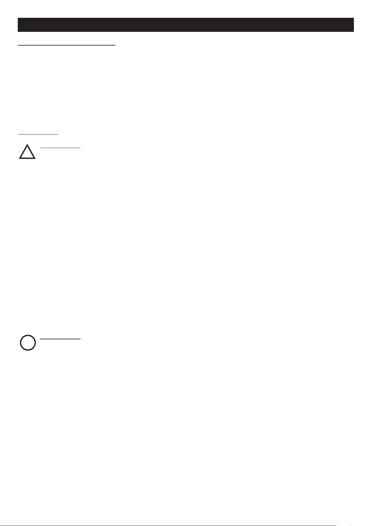
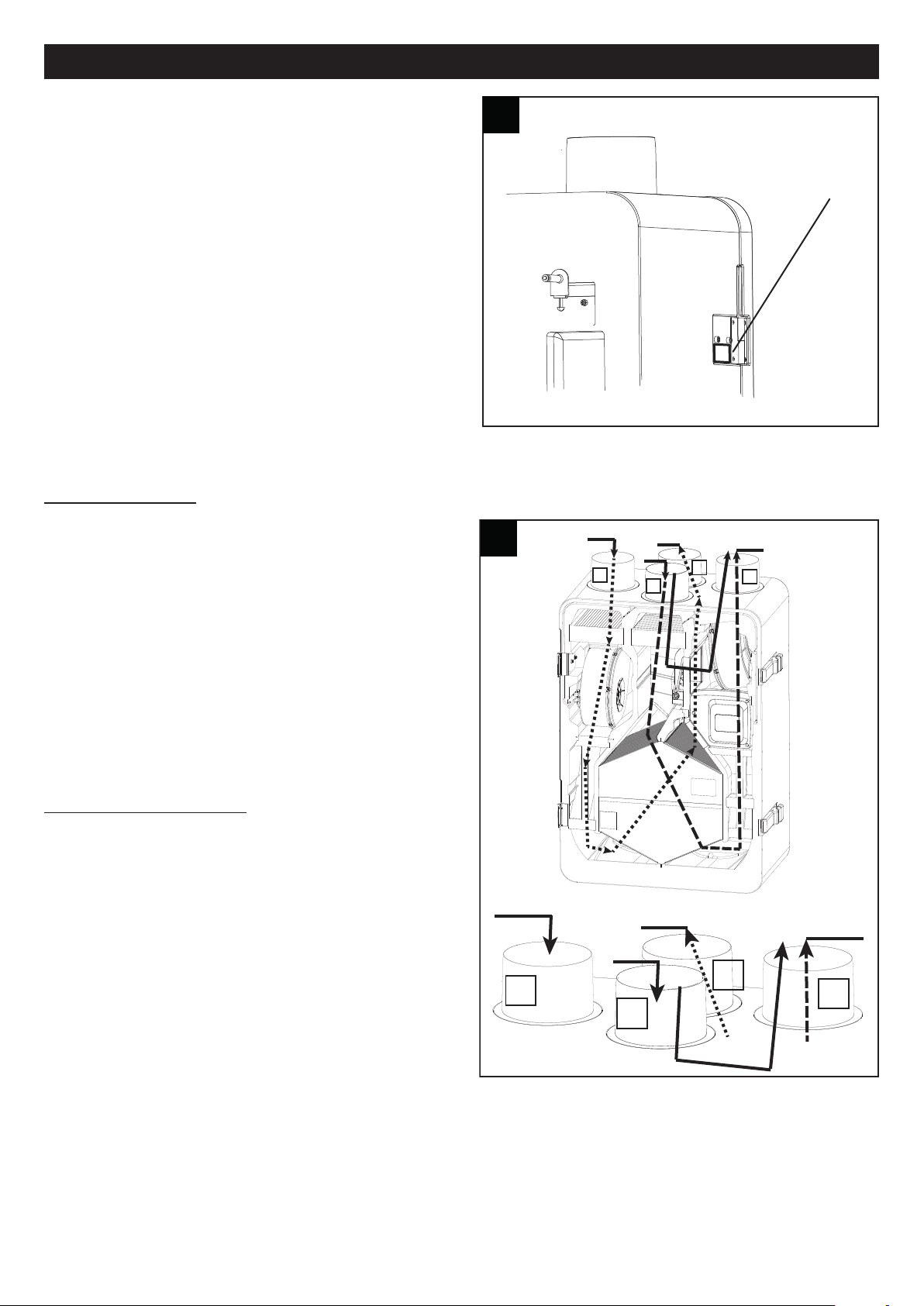
Significato delle bocchette passaggio aria (fig.2)
A: Aspirazione aria fresca dall’esterno
B: Aspirazione aria viziata da casa
C: Mandata aria pulita in casa
D: Mandata aria viziata verso l’esterno
4
Page 5
ITALIANO
3 3
350
4 4
5 5
6 6
Installazione
N.B. L’apparecchio non è adatto ad installazioni all’esterno. L’apparecchio deve essere installato seguendo le norme di
icurezza in vigore nel paese di destinazione, e le istruzioni del presente libretto. L’apparecchio deve essere installato su
s
una superficie o parete interne all’abitazione e strutturalmente adatte a reggerne il peso (max. 30 Kg). La posa in opera
dell’apparecchio non può dipendere dall’uso di adesivi. il collegamento dei condotti di aerazione alla macchina deve essere
ottenuto con uso di utensile.
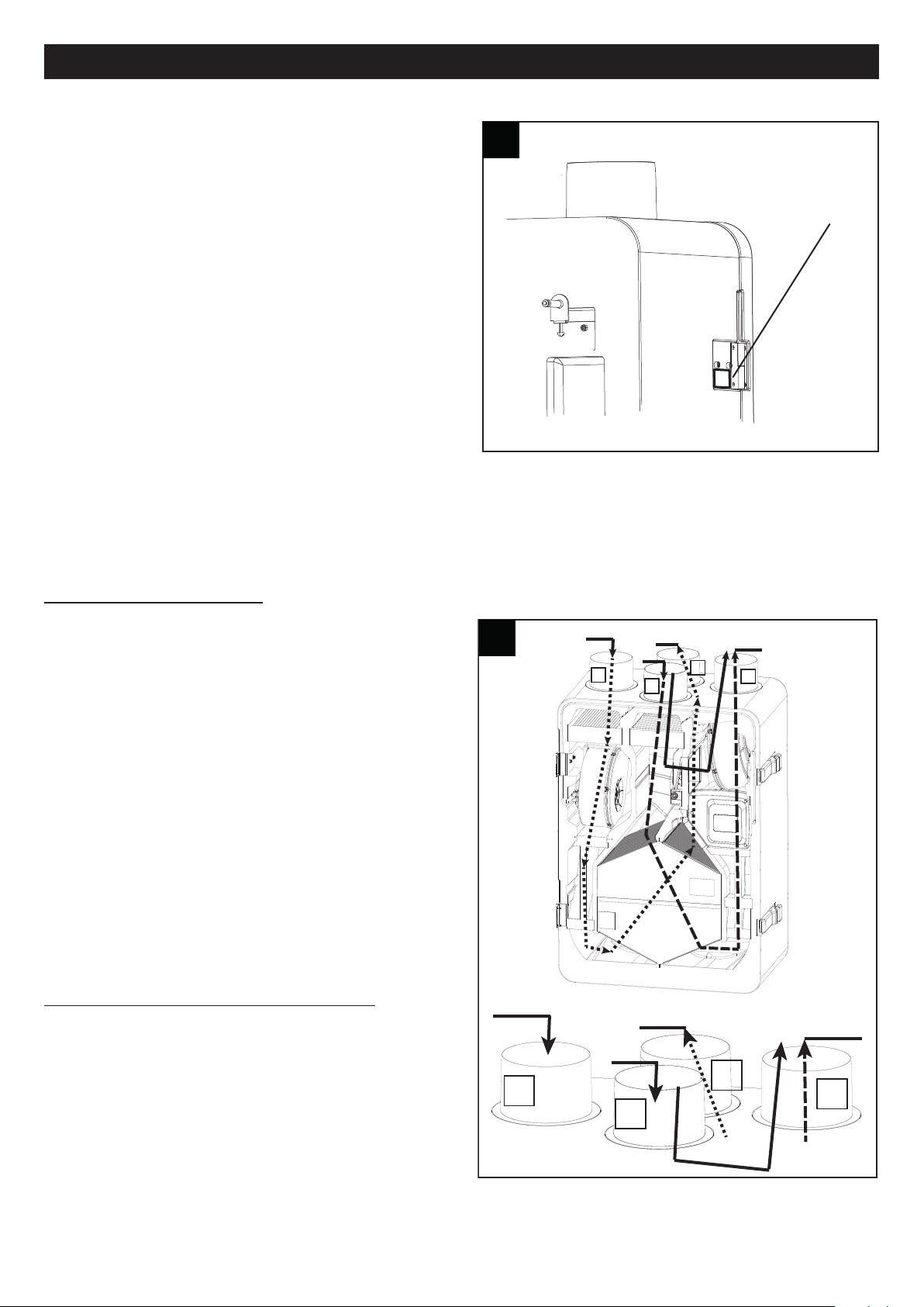
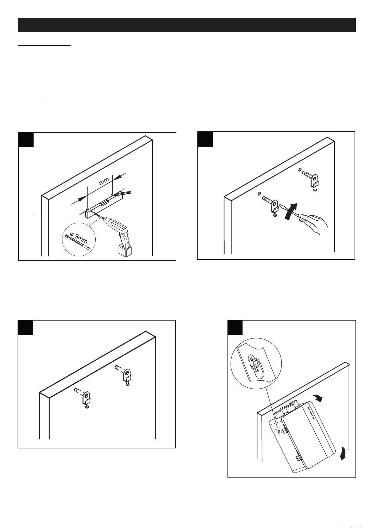
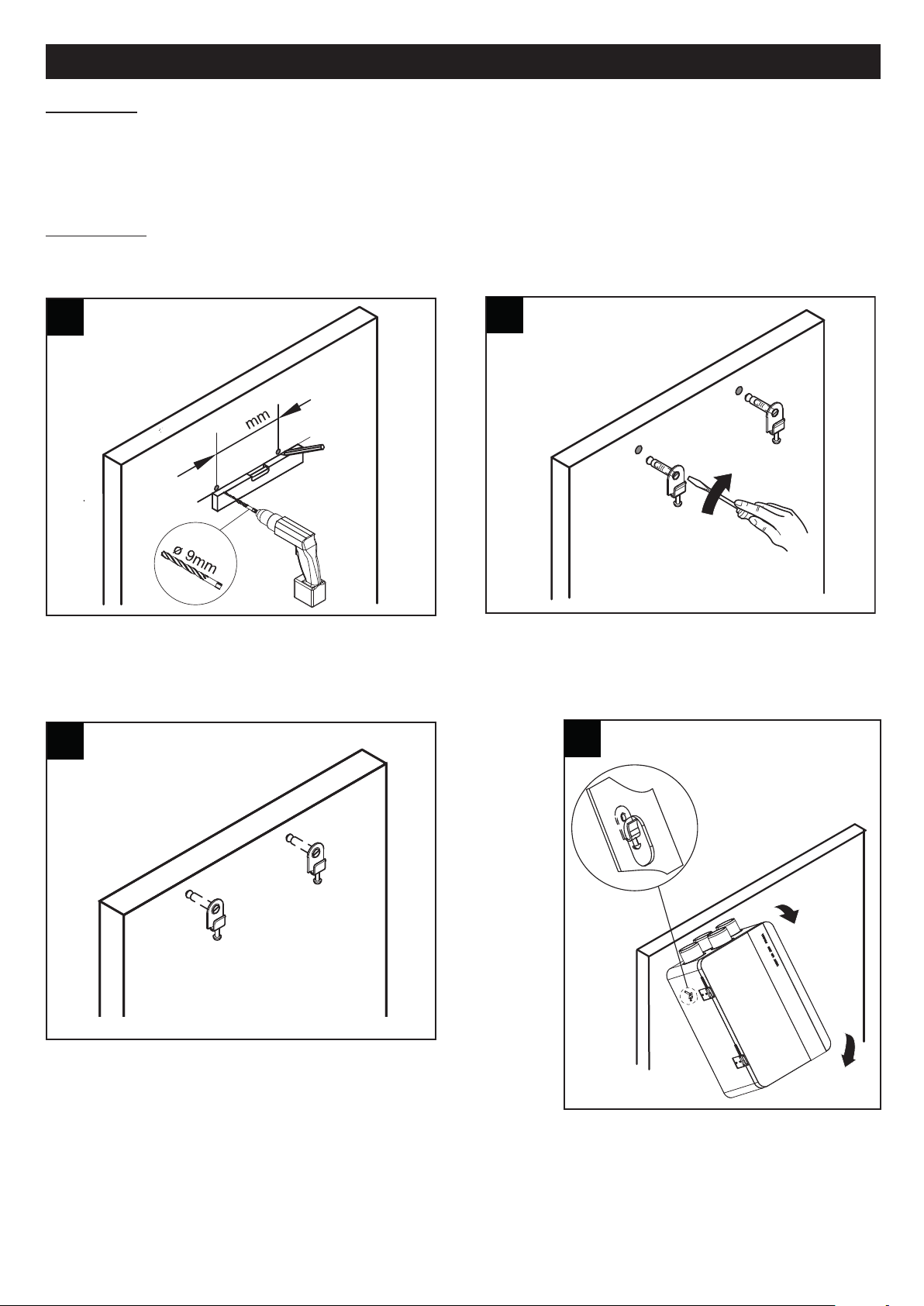
ontaggio
M
L’apparecchio può essere installato a parete (fig. 3÷7)
5
Page 6
ITALIANO
8 8
A
B
h > 50 mm∆
≥ 60 mm
9 9
7 7
Accertarsi che l’apparecchio sia in bolla, al fine di garantirne il perfetto
funzionamento.
I condotti utilizzati per le canalizzazioni devono essere delle corrette dimensioni. I condotti da e verso l’esterno devono
essere isolati termicamente e non soggetti a vibrazioni.
Le tubazioni di aspirazione e mandata, di diametro nominale pari a 125 mm devono essere fissati alle corrispondenti
bocche dell’apparecchio mediante fascette o altri sistemi di tenuta adeguati.
Se lo scarico avviene dal tetto è obbligatorio l’utilizzo di un opportuno dispositivo inteso ad evitare la formazione di
condensa e l’entrata di acqua piovana. Se l’ingresso dell’aria avviene dal tetto è obbligatorio l’utilizzo di un opportuno
dispositivo inteso ad evitare la formazione di condensa e l’entrata di acqua piovana.
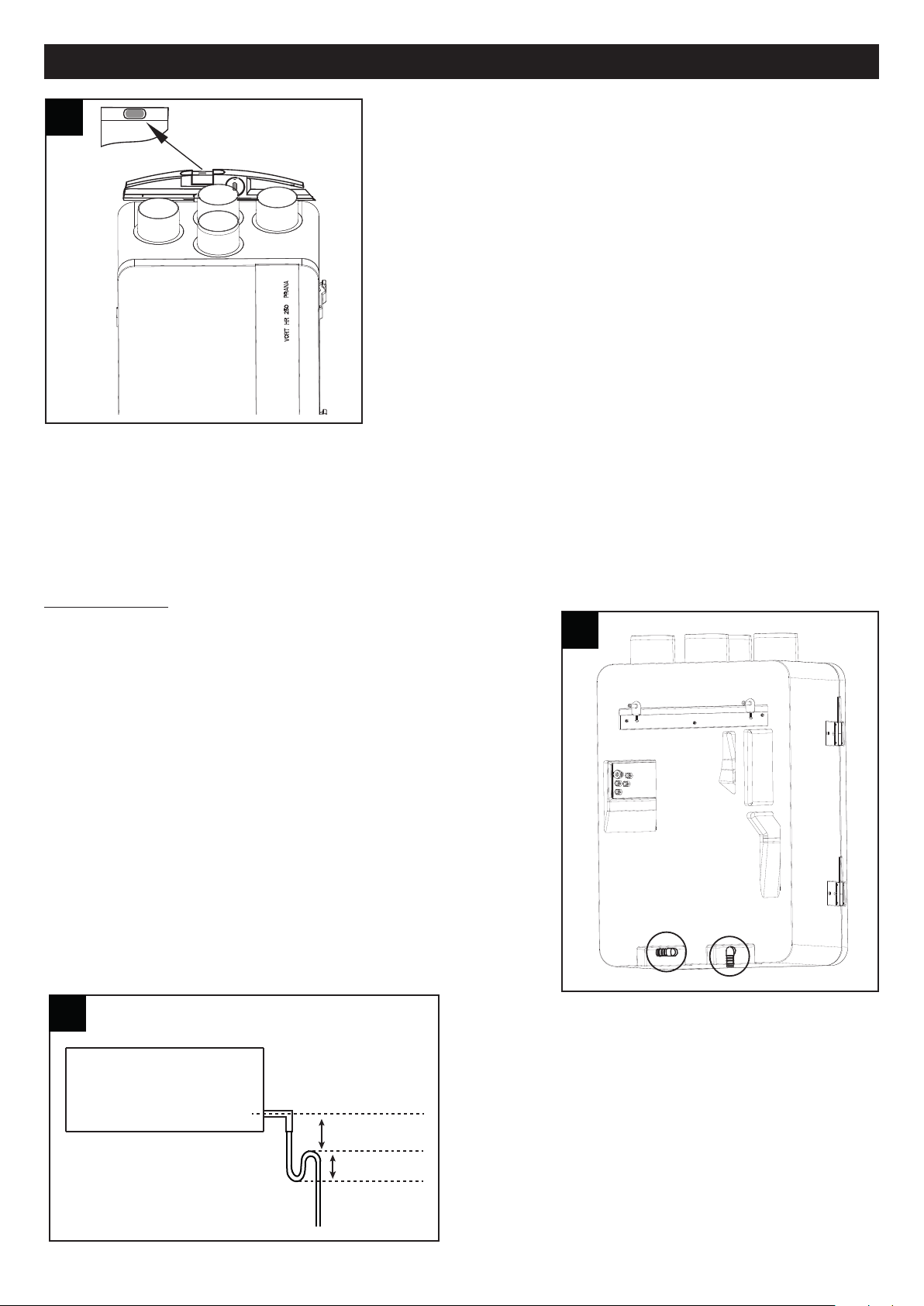
Scarico condensa
Nel corso del normale funzionamento, sul fondo dell’apparecchio si
raccoglie condensa, all’interno di una
doppia vaschetta che ha due scarichi verso l’esterno. I punti di
connessione sono posti sulla parte bassa del retro dell’apparecchio. Lo
scarico della condensa può essere realizzato connettendo agli scarichi
due tubi flessibili, di diametro interno pari a 16 mm circa. Per impedire la
formazione di bolle d’aria occorre realizzare un sifone.
Indicazioni importanti:
funzionamento invernale: alta probabilità di formazione condensa; e’
obbligatoria la connessione dei tubi di scarico, con sifone. (fig 8a)
funzionamento estivo: probabilità di formazione condensa; è consigliata
la connessione dei tubi di scarico, con sifone. (fig 8b)
Tagliare diagonalmente la terminazione del tubo.
N.B. è’ necessario realizzare il sifone rispettando le quote
indicate in fig. 9; diversamente non è garantito il regolare
funzionamento dell’apparecchio.
Lo scarico della condensa può anche essere realizzato
sfruttando il sistema di fognatura della casa.
6
Page 7
ITALIANO
From NETI
Dall'unità NETI
nero-black
blu-blue
marrone-brown
RD
L1N1BL
N2
PLC
HA
SupplySupply
TTL
BK
DI1 DI2
AO3AO4 AO5 12V
AI1
AI2 AI3 AI4 AI5GND
DO1
DO2DO3
6
LAN
BL
RD BK
1313
3
2
1
T
M
N
L
L
N
C
A
V
O
B
O
O
S
T
E
R
N
e
r
o
/
Bl
a
c
k
R
o
s
s
o
/
Re
d
C
TI
M
E
R
c
od.
1
2
9
9
9
C
TE
M
P
c
od.
1
2
9
9
2
C
S
M
O
K
E c
od.1
2
9
9
3
C
P
I
R
c
od.
1
2
9
9
8
C
H
C
S c
o
d
.1299
4
3
2
1
L
N
L
N
N
L
3 2
1
T
M
L
N
C
A
V
O
B
O
O
S
T
E
R
Ne
r
o
/
Bl
a
c
k
Ro
s
s
o
/
R
e
d
Ro
s
s
o
/
Re
d
C
A
V
O
B
O
O
S
T
E
R
Ne
r
o
/
Bl
a
c
k
1010
11 11
3
4
5
2
1
12 12
INSTALLER/USER CONTROL PANEL
PANNELLO INSTALLATORE/UTENTE
black/ GND
blue / signal
brown / +12V dc
SKW 22
Marrone / Brown (+12V dc)
Nero / Black (GND)
B
lu / Blue (segnale / signal)
POWER SUPPLY
ALIMENTAZIONE
L
N
Marrone / Brown
Blu / Blue
Giallo-Verde / Yellow-Green
1414
PR
E
-H
E
A
TER
N1L1
L N
t
t
m
arrone
/
br
ow
n
blu / blue
Da
HR
350 AV
E
L / HR 250 N
E
TI
F
rom
H
R
350
AVE
L
/
H
R 250 N
E
T
I
CAV
O
P
RE
HE
AT
E
R
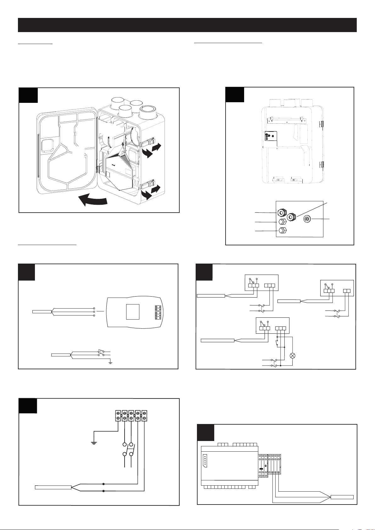
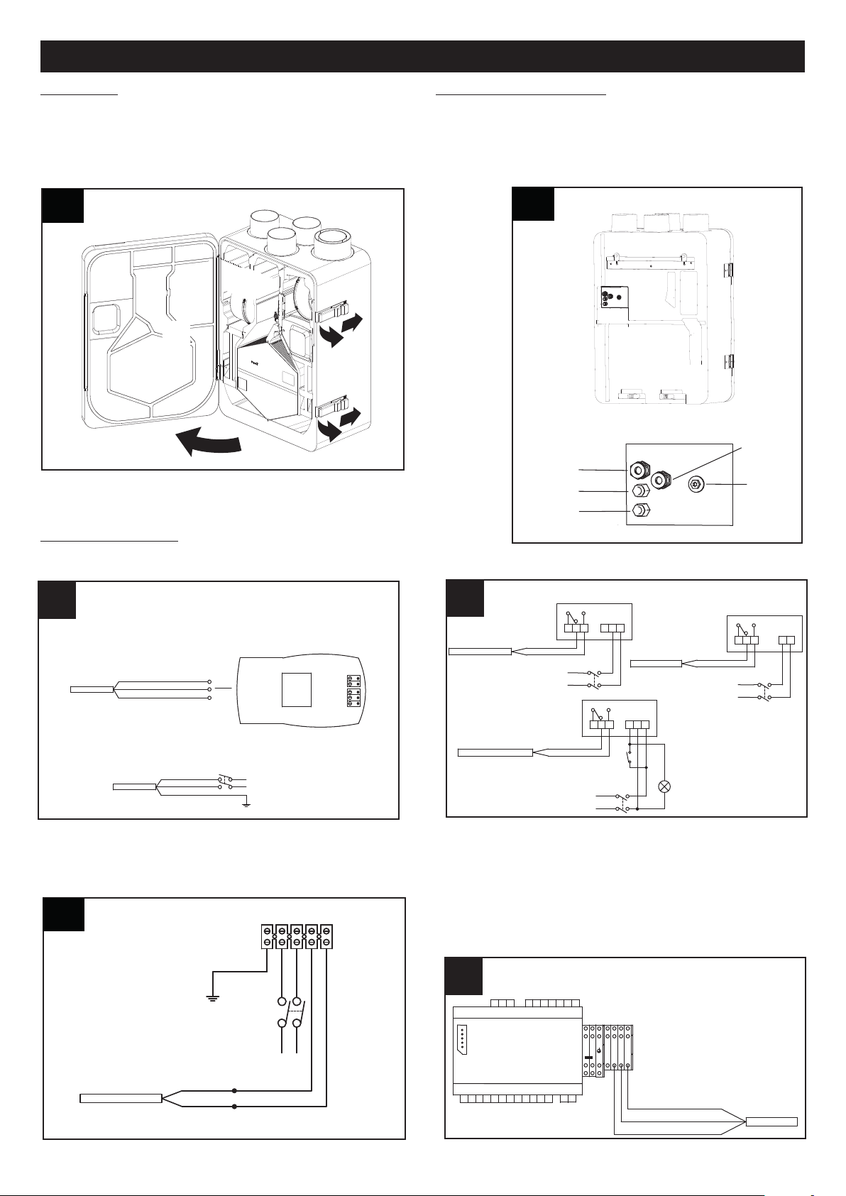
ccessibilità
A
L’apparecchio è facilmente accessibile grazie allo sportello
frontale, (fig.12) per eventuali interventi di
servizio/manutenzione, compresa la rimozione e
sostituzione dei filtri dell’aria. (Vedi anche paragrafo
Manutenzione /pulizia”)
“
ngressi scatola elettrica(fig.11)
I
2: Alimentazione
3: Cavo LAN
4: Cavo Boost
5: Cavo preheater
Collegamenti elettrici
Pannello/Alimentazione Accessori
Riscaldatore
Collegamento a Vort HA: nel caso Neti sia dotato di una unità
HA, sarà necessario connettere il recuperatore a questa
unità tramite il cavo tripolare marrone/blu/nero proveniente
dal recuperatore come in fig.15. Perciò in questo caso il
display non sarà più collegato al recuperatore ma al cavo
tripolare marrone/blu/nero già predisposto su VORT HA
come indicato sul libretto VORT HA.
7
Page 8
ITALIANO
esc set
16 16
By-Pass
/
°C
1
2345
6
7
P1 P2
Prg
A
B
C
D
E
FILT
H
A
17 17
8 9 10 11 12
14
15
16 17 19
1 2 3 4 5 6 7
20
21
Utilizzo
All’accensione, dopo 2 minuti di funzionamento, l’apparecchio ferma entrambi i motori, per permettere il riposizionamento
della valvola di bypass. I motori si riattivano dopo circa 1 minuto.
N.B.: questo comportamento del sistema è normale e non deve essere considerato come anomalia.
l prodotto ha un funzionamento in continua
I
Il controllo dell’apparecchio è realizzato tramite apposito pannello comandi dedicato, di cui nel seguito vengono descritte
le funzioni. E’ possibile l’abbinamento di un pre-riscaldatore Vortice, la cui installazione è demandata all’installatore. La
distanza minima del pre-riscaldatore dall’apparecchio è di 500 mm.
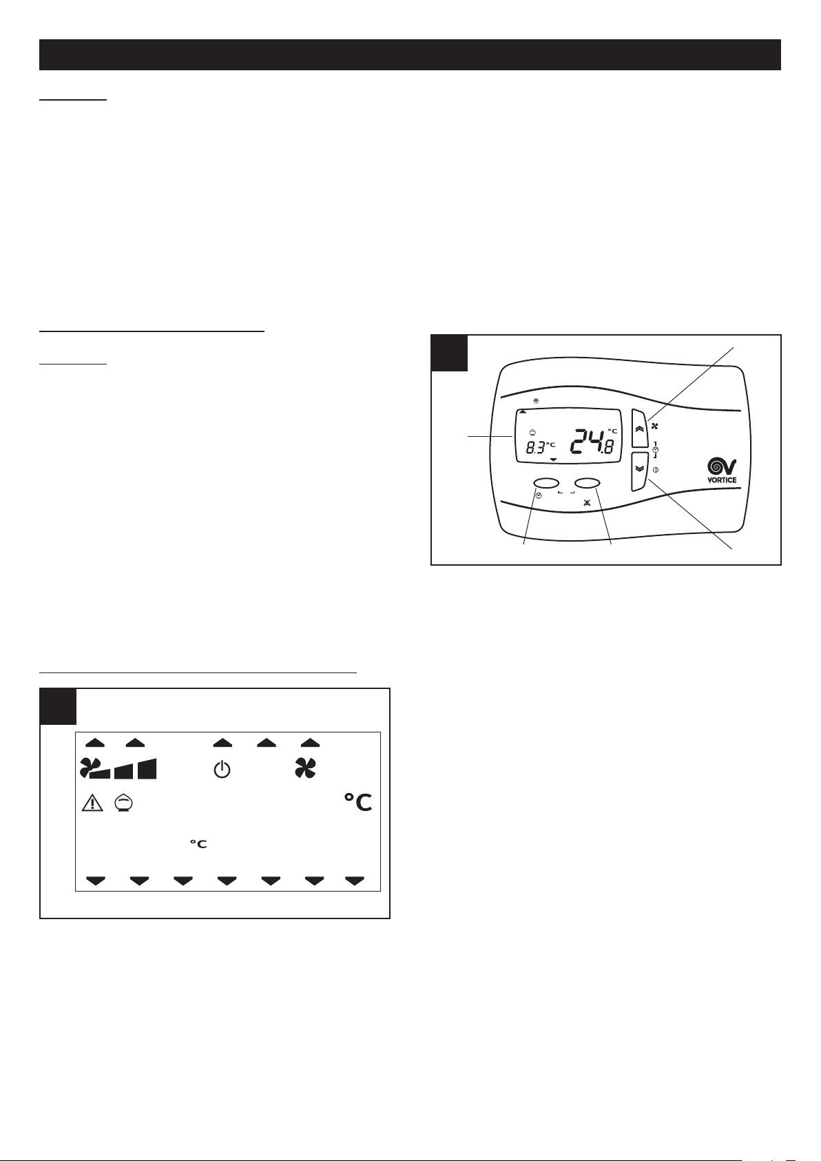
Funzioni pannello utente
Generalità (fig.16)
A = tasto “UP”: lista su
B = tasto “DOWN” : lista giù
C = tasto SET: acquisire dati
D = tasto ESC: uscire
E = display
L’utente dispone di un pannello con cui può gestire i
parametri di funzionamento dell’apparecchio:
- accensione/spegnimento (mercati NO UK)
- ora/giorno corrente (mercati NO UK o modelli dotati di HA)
- velocità di funzionamento
- temperatura ambiente richiesta
- forzatura funzione “bypass”
- funzionamento “HA”(per i modelli dotati di modulo HA)
Il pulsante ESC, quando non diversamente specificato, ha sempre la funzione di uscire senza salvare dati.
Quadro riassuntivo delle icone presenti sul pannello (fig.17)
1÷7giorno della settimana ( mercati NO UK o modelli dotati di
HA): 1=lunedì, 2=martedì, ecc.
8 allarme filtri: l’accensione dell’icona indica che entro tre
mesi è necessario sostituire i filtri; se la sostituzione non
avviene entro tale periodo il sistema entra in blocco (solo
modelli UK) e segnala l’errore filtri FILT (vedi paragrafo
“Visualizzazione menu allarmi”)
9 funzione no-frost: l’accensione dell’icona fissa indica che
è attiva la procedura di no-frost; l’icona lampeggiante
indica una condizione di “no-frost timeout”: la procedura di
no-frost in questo caso non è sufficiente e l’apparecchio
entra in protezione per un’ora, a motori fermi, dopo di che
il sistema riattiva la macchina.
10 profilo orario P1: vedi paragrafo “Menu Utente” (mercati
NO UK o modelli dotati di HA)
11 profilo orario P2: vedi paragrafo “Menu Utente” (mercati NO UK o modelli dotati di HA)
12 HA: (solo modelli dotati di HA)
14 velocità attuale di funzionamento: l’accensione delle icone fisse indica a quale delle 3 velocità sta funzionando
l’apparecchio.
15 stato di stand-by del sistema: l’accensione dell’icona fissa indica che l’apparecchio è in stand-by (acceso ma con i
motori spenti), per la presenza di un allarme (mercato UK) o perchè il sistema è spento (mercati NO UK); l’icona
lampeggiante (mercati NO UK) indica che l’apparecchio è in stand by a seguito della programmazione delle fasce orarie
(vedi paragrafo “Programmazione dei profili orari”);
16 l’accensione dell’icona indica la presenza di un allarme; l’icona lampeggiante segnala che è stato presente un allarme
17 funzione bypass: l’icona indica: (vedi anche paragrafo “Attivazione funzione Bypass”)
8
a riarmo manuale; (vedi paragrafo “Visualizzazione menu allarmi”
Page 9
ITALIANO
esc set
By-Pass
/ °C
1234567
F
ILT
P1 P2
Prg
HA
esc set
By-Pass
/ °C
1234567
FILT
P1 P2
Prg
20 20
HA
esc set
By-Pass
/ °C
12345
6
7
FILT
P1 P2
Prg
18 18
HA
penta: bypass disattivato
s
accesa fissa: bypass aperto tramite comando manuale
lampeggiante: bypass aperto automaticamente via software (in questo caso non è possibile chiudere il bypass
manualmente)
19 gradi Celsius temperatura interna
20 visualizzazione temperatura esterna gradi Celsius
21 Boost attivo
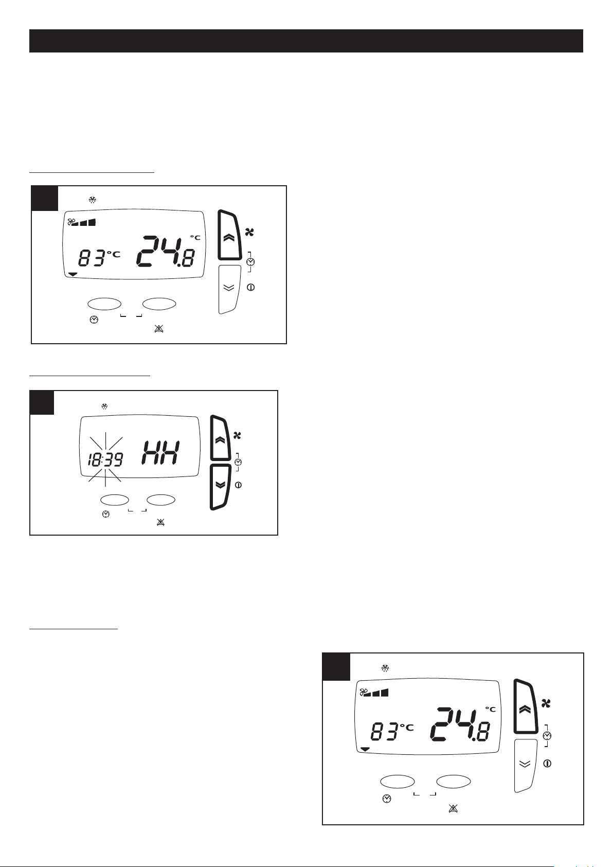
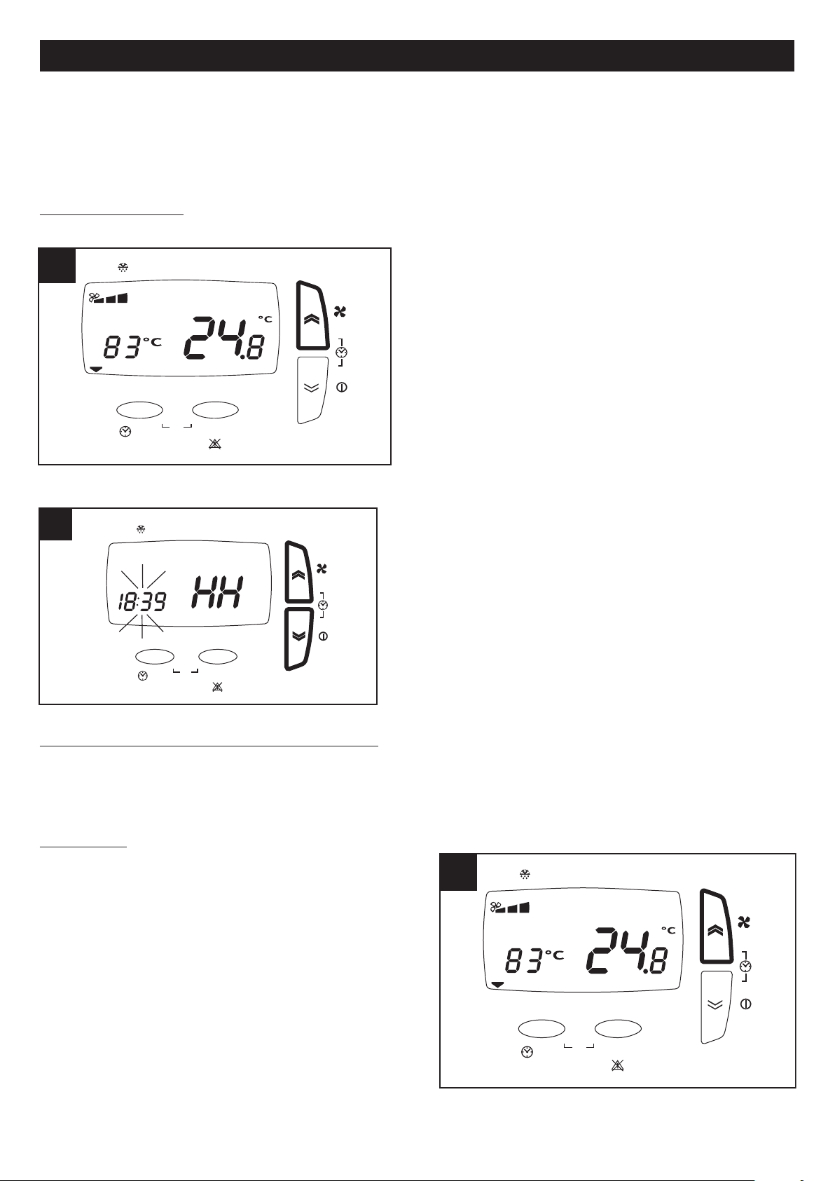
Accensione/spegnimento (solo mercati NO UK) (fig.18)
’apparecchio si accende/spegne tramite una pressione lunga
L
sul tasto “down” del pannello. In fase di spegnimento dopo aver
tenuto premuto il tasto “down” l’apparecchio resterà attivo in
modalità BOOST, per circa 2 minuti prima dello spegnimento.
Impostazione ora/giorno
(solo mercati NO UK o modelli dotati di HA) (fig.19)
Selezione velocità (fig.20)
Prima di eseguire i passi indicati nel seguito premere il tasto
ESC per uscire e posizionarsi sul menu iniziale.
La velocità di funzionamento, preimpostata in fase di
configurazione, può essere selezionata con una pressione
breve sul tasto “up” (1=Vel min, 2=Vel med, 3=Vel max).
Prima di eseguire i passi indicati nel seguito premere il tasto
ESC per uscire e posizionarsi sul menu iniziale.
L’ora e il giorno corrente possono essere impostati nel modo
seguente:
- pressione breve simultanea dei pulsanti “up” e “down”
- pressione breve pulsanti “up” e “down”, per regolazione
parametro “ora” (HH);
- pressione breve pulsante SET per acquisizione dato “ora” e
passaggio a parametro “minuti” (MM);
- pressione breve pulsanti “up” e “down”, per regolazione
parametro “minuti” ;
- pressione breve pulsante SET per acquisizione dato “minuti” e
passaggio a parametro “giorno” (dAy);
- pressione breve pulsanti “up” e “down”, per regolazione
parametro “giorno”;
- pressione breve pulsante SET per acquisizione dato “giorno” e
uscita.
9
Page 10

esc set
By-Pass
/ °C
12345
6
7
FILT
P2
Prg
24 24
P1
HA
ITALIANO
esc set
By-Pass
/ °C
1234567
FILT
P1 P2
Prg
22 22
HA
esc set
By-Pass
/ °C
1234567
FILT
P
1 P2
Prg
23 23
HA
esc set
B
y-Pass
/
°C
12345
6
7
FILT
P
1 P2
Prg
21 21
HA
mpostazione temperatura ambiente richiesta(fig.21)
I
Prima di eseguire i passi indicati nel seguito premere il tasto
ESC per uscire e posizionarsi sul menu iniziale.
La temperatura ambiente desiderata può essere selezionata
el seguente modo:
n
- pressione lunga del pulsante SET
- pressione breve del pulsante SET (il valore corrente
lampeggia)
- selezione del valore desiderato tramite pulsanti “up” e
down”
“
- pressione breve del pulsante SET per acquisire il dato
- pressione breve del pulsante ESC per uscire
Attivazione funzione “bypass”
(fig.22)
Lo scopo della funzione bypass è ventilare l’appartamento
senza trasferimenti di calore. L’apertura della valvola di bypass consente l’immissione diretta dell’aria esterna,
evitandone il passaggio all’interno dello scambiatore di
calore. Il flusso d’aria espulsa dalla casa continua invece a
transitare attraverso lo scambiatore.
Prima di eseguire i passi indicati nel seguito premere il tasto
ESC per uscire e posizionarsi sul menu iniziale.
La funzione “bypass” può essere forzata tramite pressione
lunga del pulsante ESC. Si accenderà l’icona corrispondente
“salvadanaio” (la funzione rimarrà attiva per 12 ore, dopo di
che l’apparecchio tornerà al funzionamento automatico)
Attivazione visualizzazione ora/temperatura esterna (solo mercati NO UK o modelli dotati di HA) (fig.23)
Prima di eseguire i passi indicati nel seguito premere il tasto
ESC per uscire e posizionarsi sul menu iniziale.
I valori attuali dei parametri “ora” e “temperatura esterna”
possono essere visualizzati alternativamente tramite pressione
breve del pulsante ESC.
Menu utente (fig.24)
10
Prima di eseguire i passi indicati nel seguito premere il tasto
ESC per uscire e posizionarsi sulla schermata iniziale.
In generale i parametri relativi alle varie opzioni sono
impostabili premendo SET (il valore corrente inizia a
lampeggiare), selezionando i diversi valori tramite i pulsanti
UP e DOWN e premendo nuovamente SET per acquisire il
nuovo valore. Anche lo scorrimento tra le diverse opzioni o
parametri avviene tramite i pulsanti UP e DOWN.
Il menu generale utente può essere visualizzato tramite la
pressione simultanea dei pulsanti ESC e SET. Le opzioni del
menu sono:
Page 11
ITALIANO
esc set
By-Pass
/ °C
1234567
FILT
P2
Prg
26 26
P1
HA
esc set
By-Pass
/
°C
1
234 5
6
7
F
ILT
P2
P
rg
25 25
P1
HA
PROF(solo mercati NO UK): impostazioni funzionamento con profili orari:
-
P1 permette di programmare un intervallo di funzionamento al giorno, con un orario di inizio, un orario di fine e una
velocità;
P2 permette di programmare due intervalli di funzionamento al giorno, ognuno con un orario di inizio , un orario di fine
e una velocità.
’ possibile assegnare un profilo diverso ad ogni giorno della settimana.
E
: impostazioni impostazioni funzionamento HA: presente solo su apparecchi dotati di modulo HA;
- HA
- SERV: servizio (opzione riservata all’installatore).
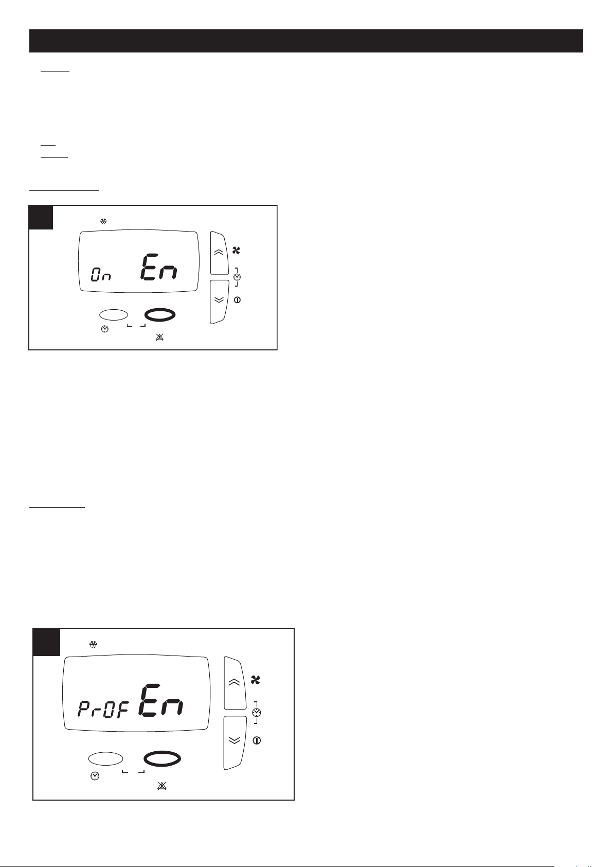
Opzione PROF (solo mercati NO UK) (fig.25)
Selezionando PROF tramite pulsante SET si entra nelle
impostazioni dei profili orari. I parametri sono:
- En (Enable): i valori possibili sono:
ON: abilita il funzionamento con profili (e come detto
sopra viene automaticamente disabilitato l’eventuale
funzionamento in modalità HA)
OFF: disabilita il funzionamento con profili.
Se è stato selezionato EN ON vengono abilitati anche i seguenti
parametri:
- ST: orario inizio intervallo di profilo P1
- END: orario fine intervallo di profilo P1
- ST1 : orario inizio intervallo 1 di profilo P2
- EN1 : orario fine intervallo 1 di profilo P2
- ST1 : orario inizio intervallo 2 di profilo P2
- EN1 : orario fine intervallo 2 di profilo P2
- MON: assegnazione profilo al giorno lunedi: i valori possibili sono P1 e P2
- TUE: assegnazione profilo al giorno martedi: i valori possibili sono P1 e P2
- UED: assegnazione profilo al giorno mercoledi: i valori possibili sono P1 e P2
- THR: assegnazione profilo al giorno giovedi: i valori possibili sono P1 e P2
- FRY: assegnazione profilo al giorno venerdi: i valori possibili sono P1 e P2
- SAT: assegnazione profilo al giorno sabato: i valori possibili sono P1 e P2
- SUN: assegnazione profilo al giorno domenica: i valori possibili sono P1 e P2
Opzione HA (fig.26)
L’opzione è disponibile solo per i modelli dotati di modulo HA
Selezionando HA tramite pulsante SET si entra nelle impostazioni della modalità HA. I parametri sono:
- En (Enable): i valori possibili sono:
PROF: abilita la modalità HA con profili
ON: abilita la modalità HA continua
OFF: disabilita la modalità HA
HOL: abilità la modalità HOLIDAY: due ore di funzionamento antibatterico al giorno, due ore di rinnovo aria, 20 ore di
stand-by.
Se è stato selezionato EN PROF vengono abilitati anche
i seguenti parametri:
- ST: orario inizio intervallo di profilo P1
- END: orario fine intervallo di profilo P1
- ST1 : orario inizio intervallo 1 di profilo P2
- EN1 : orario fine intervallo 1 di profilo P2
- ST1 : orario inizio intervallo 2 di profilo P2
- EN1 : orario fine intervallo 2 di profilo P2
- MON: assegnazione profilo al giorno lunedi: i valori
possibili sono P1 e P2
- TUE: assegnazione profilo al giorno martedi: i valori
possibili sono P1 e P2
- UED: assegnazione profilo al giorno mercoledi: i valori
possibili sono P1 e P2
11
Page 12
ITALIANO
esc set
B
y-Pass
/ °C
1
234 5
6
7
F
ILT
P
1 P2
P
rg
27 27
H
A
THR: assegnazione profilo al giorno giovedi: i valori possibili sono P1 e P2
-
- FRY: assegnazione profilo al giorno venerdi: i valori possibili sono P1 e P2
- SAT: assegnazione profilo al giorno sabato: i valori possibili sono P1 e P2
- SUN: assegnazione profilo al giorno domenica: i valori possibili sono P1 e P2
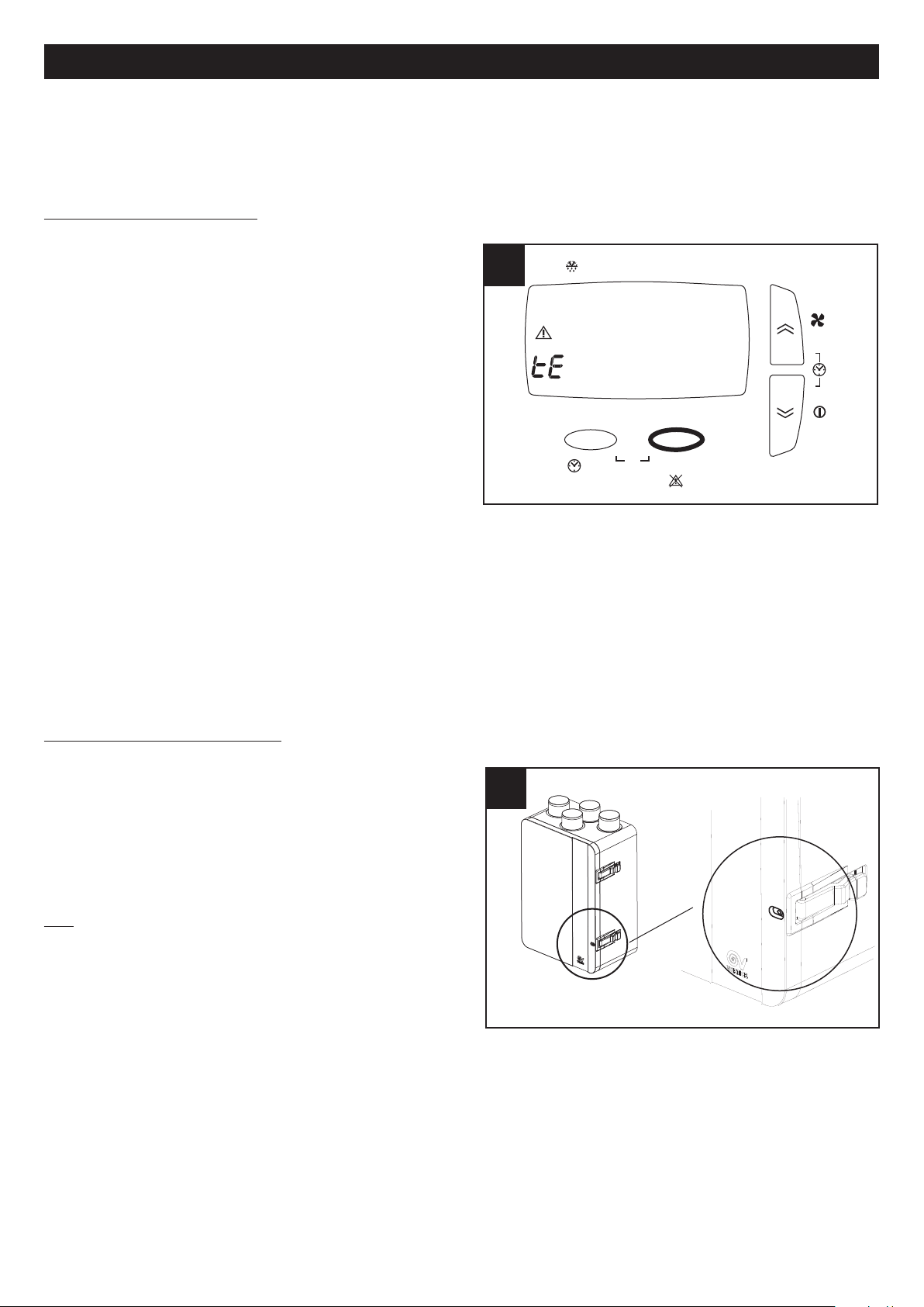
Visualizzazione menu allarmi
(fig.27)
Prima di eseguire i passi indicati nel seguito premere il tasto
ESC per uscire e posizionarsi sul menu iniziale.
e segnalazioni d’allarme eventualmente presenti possono
L
essere visualizzate nel seguente modo:
--pressione lunga del pulsante SET
--pressione breve su UP o DOWN in modo da visualizzare il
menu ALRM
--pressione breve del pulsante SET per visualizzare il codice
d’errore attivo
Il sistema può presentare diverse situazioni d’allarme,
evidenziate come segue sul pannello utente:
: sensore temperatura interna guasto; richiedere l’intervento
ti
dell’ Assistenza Tecnica;
tout: sensore temperatura esterna guasto; richiedere
l’intervento dell’ Assistenza Tecnica;
te: sensore temperatura aria di scarico guasto; richiedere l’intervento dell’ Assistenza Tecnica;
preh: pre-heater guasto, o non presente (se previsto); richiedere l’intervento dell’ Assistenza Tecnica;
Hito: temperatura esterna superiore a 45° C; richiedere l’intervento dell’ Assistenza Tecnica;
Hiti: temperatura interna superiore a 45° C; richiedere l’intervento dell’ Assistenza Tecnica;
Filt: è necessario sostituire i filtri saturi (3 mesi). Dopo la sostituzione dei filtri l’errore è resettabile dall’utente: a tale scopo
è sufficiente una pressione lunga simultanea dei tasti UP e DOWN.
N.B. Il reset degli errori a riarmo manuale è possibile tramite pressione lunga del tasto UP e DOWN.
Manutenzione e pulizia
Prima di iniziare qualsiasi operazione accertarsi che il
prodotto sia scollegato dalla rete elettrica. Lo smontaggio e
relativo montaggio sono operazioni di manutenzione
straordinaria e devono essere eseguite da personale
professionalmente qualificato.
N.B. Prima di aprire lo sportello svitare la vite di sicurezza
frontale. (fig.28)
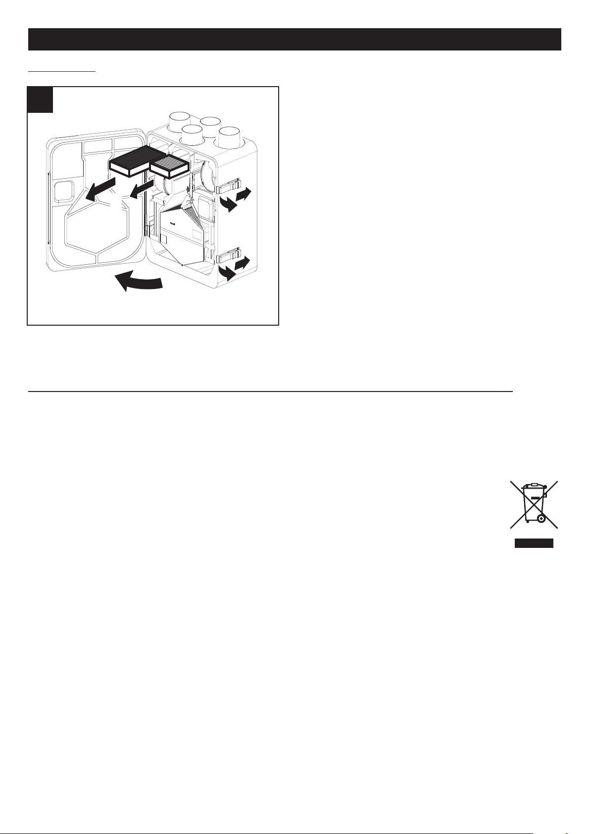
Filtri
Tempi consigliati per la manutenzione: In generale in funzione
dell’area geografica di installazione il livello di inquinamento
dell’aria è variabile, e quindi è variabile la durata dei filtri.
Tenendo presenti queste considerazioni i tempi per la
manutenzione dei filtri sono i seguenti:
Ispezione filtri: ogni 50/60 giorni;
sostituzione filtri: dopo 3 o 12 mesi (mercati UK), 3 o 24 mesi (mercati no UK) (in base a quanto impostato in fase di
installazione dall’installatore) appare sul display un messaggio di preallarme che avvisa l’utente che è necessario sostituire
i filtri. Da questo momento i filtri devono essere sostituiti entro 3 mesi (mercati UK) , 2 mesi (mercati no UK); allo scadere
l’apparecchio si arresta (solo mercati UK) e si attiva l’allarme di filtri saturi (Filt). Con il reset dell’errore (descritto nel
paragrafo “Visualizzazione menu allarmi”) viene resettato anche il contatore.
N.B. La mancata pulizia o sostituzione dei filtri comporta gravi inconvenienti per l’efficienza dell’impianto, con:
- aumento delle perdite di carico nel circuito aria e riduzione di portata aria;
- conseguente diminuzione della resa della macchina e peggioramento del confort in ambiente.
N.B. La situazione di filtri saturi rappresenta la causa più frequente di blocco dell’apparecchio: (Filt)
12
Page 13
ITALIANO
29 29
1
2
3
Estrazione filtri: fig.29
Informazione importante per lo smaltimento ambientalmente compatibile
IN ALCUNI PAESI DELL'UNIONE EUROPEA QUESTO PRODOTTO NON RICADE NEL CAMPO DI APPLICAZIONE
DELLA LEGGE NAZIONALE DI RECEPIMENTO DELLA DIRETTIVA RAEE E QUINDI NON È IN ESSI VIGENTE
ALCUN OBBLIGO DI RACCOLTA DIFFERENZIATA A FINE VITA.
Questo prodotto è conforme alla Direttiva EU2002/96/EC.
Il simbolo del bidone barrato riportato sull’apparecchio indica che il prodotto, alla fine della propria vita utile,
dovendo essere trattato separatamente dai rifiuti domestici, deve essere conferito in un centro di raccolta
differenziata per apparecchiature elettriche ed elettroniche oppure riconsegnato al rivenditore al momento
dell’acquisto di una nuova apparecchiatura equivalente.
L’utente è responsabile del conferimento dell’apparecchio a fine vita alle appropriate strutture di raccolta,
pena le sanzioni previste dalla vigente legislazione sui rifiuti.
L’adeguata raccolta differenziata per l’avvio successivo dell’apparecchio dismesso al riciclaggio, al trattamento e allo
smaltimento ambientalmente compatibile contribuisce ad evitare possibili effetti negativi sull’ambiente e sulla salute e
favorisce il riciclo dei materiali di cui è composto il prodotto.
Per informazioni più dettagliate inerenti i sistemi di raccolta disponibili, rivolgersi al servizio locale di smaltimento rifiuti o al
negozio in cui è stato effettuato l’acquisto.
I produttori e gli importatori ottemperano alla loro responsabilità per il riciclaggio, il trattamento e lo smaltimento
ambientalmente compatibile sia direttamente sia partecipando ad un sistema collettivo.
13
Page 14
ENGLISH
Description and use
Vort HR 250 Neti (hereafter “the appliance”) is a heat recovery unit for residential use, featuring high heat exchange
fficiency, low power consumption and compact size. The appliance is controlled by a hi-tech electronic management
e
system and equipped with fan units that utilize EC brushless motors. A heat exchanger is fitted inside the appliance to
guarantee heat exchange efficiency levels >85%. The appliance is equipped with an automatic by-pass function and
integrated antifreeze protection. (See “Use” for a more detailed description of the various functions).
These appliances have been designed for use in residential and commercial properties.
Safety
Warning:
this symbol indicates that care must
!
be taken to avoid injury to the user
• Follow the safety instructions to prevent any harm to the user.
• Do not use this appliance for purposes other than those described in this manual.
• Having removed the appliance from its packaging, make certain it is intact and undamaged. If in doubt, consult a
professional or contact a Vortice Technical Support Centre.
• Do not leave packaging within reach of children or individuals with disabilities.
• Certain basic rules must always be observed when using any electrical appliance: never touch the appliance with wet or
damp hands; never touch the appliance when barefoot.
• Do not operate the appliance in the presence of flammable substances or vapours, such as alcohol, insecticides, petrol,
etc.
• If the appliance is to be disconnected from the power supply and no longer used, store it out of reach of children and
individuals with disabilities.
• Take precautions to avoid any backdraught of gases into the room from the flue or from other open flame appliances.
• To avoid any risks associated with the accidental resetting of the thermal cutout, this appliance should not be powered
using an external switching device, such as a timer, or connected to a circuit that is powered up and shut off on a regular
basis.
• This appliance can be used by children no less than 8 years of age and by individuals with limited
physical, sensory or mental capacities, or by inexperienced or untrained individuals, provided that
they are supervised or have been instructed in safe use of the appliance and understand the
associated risks. Children must not play with the appliance. Cleaning and maintenance procedures for which the user is responsible - must not be carried out by children unless supervised.
Caution:
this symbol indicates that care must
!
be taken to avoid damaging the appliance
• Do not make modifications of any kind to this appliance.
• The maintenance instructions must be followed to ensure the appliance does not suffer damage and/or excessive wear.
• Do not expose this appliance to the elements (rain, sun, etc.).
• Do not stand objects on the appliance.
• The inside of the appliance must be cleaned only by a skilled professional.
• Inspect the appliance periodically for visible defects. If the appliance is defective in any way, do not use it; contact a Vortice
Technical Support Centre without delay.
• If the appliance does not function correctly or develops a fault, contact a Vortice Technical Support Centre without delay.
Ensure that only original Vortice replacement parts are used for any repairs.
• If the power cable is damaged, have it replaced without delay by a Vortice Technical Support Centre.
• Should the appliance be dropped or suffer heavy impact, have it checked without delay by a Vortice Technical Support
Centre.
• The appliance must be installed in such a way as to ensure that under normal operating conditions, no one can come into
contact with any moving parts or live electrical components.
• In the event of: dismantling the appliance, with the appropriate tools; removing the heat exchanger; removing the motor
module; the appliance must first be switched off and then disconnected from the mains electricity supply.
• The electrical system to which the appliance is connected must comply with current regulations.
• Connect the appliance to the electrical power supply/socket only if the rated power of the supply is compatible with the
maximum rated power of the appliance. If not, contact a professional electrician without delay.
• Turn off the appliance at the main switch: if the appliance does not function correctly; before cleaning the outside of the
appliance, if the appliance is not going to be used for any length of time.
14
Page 15
ENGLISH
1 1
A
A
B
C
D
Out
In
In
Out
Bp
2 2
A
B
C
D
Out
In
In
Out
Bp
The appliance cannot be used to pilot the operation of water
•
heaters, stoves, etc.; neither must it drain into the hot water
ducts of such appliances.
• The appliance must expel air directly to the outside through
a single dedicated duct.
The flow of extracted air must be clean (i.e. free of grease,
•
soot, chemical and corrosive agents and explosive or
flammable mixtures).
• Keep the air intake and outlet ports of the appliance free of
obstructions, to ensure optimum air flow.
Maximum operating temperature: 45°C.
•
• Specifications for the power supply must correspond to the
electrical data on ID plate A (Fig. 1).
• The appliance must be installed by a
professionally qualified technician.
• The appliance must be wired to the power supply
by way of a multi-pole isolating switch with a gap
of at least 3 mm between contacts.
Items supplied
The main parts of the appliance are:
• an outer casing made using an expanded polypropylene
shell and a hinged hatch (removable);
• a cross and counter flow heat exchanger, made of
polystyrene, featuring a special geometry designed to
guarantee ultra high efficiency in terms of heat exchange
(>85%);
• two energy-saving variable speed brushless motors (2
preset speeds);
• electronic circuits supervising the power input, monitoring
and control of the appliance;
• temperature sensors (bypass and defrost);
• remote controller (wall installation);
• two G4 filters ( 1 M5 filter optional;
Key to air connections (Fig.2)
A: Fresh air intake from outside
B: Stale air intake from room
C: Clean air outlet inside the room
D: Stale air outlet to outside
15
Page 16

ENGLISH
3 3
350
4 4
5 5
6 6
Installation
N.B. The appliance is not suitable for outdoor installation. The appliance must be installed in accordance with current safety
egulations in the destination country, and with the instructions in this booklet. The appliance must be installed on an
r
internal surface or wall of the home structurally suited to holding its weight (max. 30 kg). The appliance cannot be positioned
and secured in place using only adhesives. The connection of the ventilation ducts to the appliance must be made with the
aid of a tool.
ounting
M
The appliance can be wall-mounted (fig.3÷7).
16
Page 17

ENGLISH
7 7
8 8
A
B
h > 50 mm∆
≥ 60 mm
9 9
Make sure that the appliance is level in order to ensure faultless operation.
The ducts used for conveying air must be of the correct size. The ducts to and from the outdoors must be thermally
insulated and not subject to vibration. The 125 mm standard diameter inlet and outlet ducts must be secured to the
corresponding ports of the appliance by means of clips or other suitable fastening systems. If stale air is exhausted via the
roof, the outlet must be designed so as to prevent the formation of condensate and the entry of rain water. If fresh air enters
via the roof, the intake must be designed so as to prevent the formation of condensate and the entry of rain water.
Condensate drain
During normal operation, condensate collects at the bottom of the appliance in a double tray provided with two drain outlets.
The connection points are located at the back of the appliance, towards
the bottom. The condensate drain can be provided by connecting the
drain outlets to two flexible hoses with an internal diameter of 16 mm
approx. A siphon trap should be created to prevent air bubbles from
forming. Important instructions: winter operation: high probability of
condensate forming; drain hoses must be connected, with a siphon trap.
(Fig.8a) summer operation: probability of condensate forming; drain
hoses should be connected, with a siphon trap. (Fig.8b)
Cut the end of the hose obliquely
N.B. The siphon must be created observing the dimensions
indicated in fig. 11, otherwise correct operation of the
appliance cannot be guaranteed. Condensate can also be
drained off through the waste plumbing system of the building.
17
Page 18
ENGLISH
1010
11 11
3
4
5
2
1
12 12
INSTALLER/USER CONTROL PANEL
PANNELLO INSTALLATORE/UTENTE
b
lack/ GND
b
lue / signal
brown / +12V dc
SKW 22
M
arrone / Brown (+12V dc)
Nero / Black (GND)
B
lu / Blue (segnale / signal)
POWER SUPPLY
ALIMENTAZIONE
L
N
Marrone / Brown
Blu / Blue
Giallo-Verde / Yellow-Green
1414
PRE-HEATER
N1L1
LN
tt
marrone / brown
blu / blue
Da HR 350 AVEL / HR 250 NETI
From HR 350 AVEL / HR 250 NETI
CAVO PREHEATER
From NETI
Dall'unità NETI
nero-black
blu-blue
marrone-brown
RD
L1N1BL
N2
PLC
HA
SupplySupply
TTL
BK
DI1 DI2
AO3AO4 AO5 12V
AI1
AI2 AI3 AI4 AI5GND
DO1
DO2DO3
6
LAN
BL
RD BK
1313
321 TMNL
L
N
C
AVO BOOSTER
Nero / Black
Rosso / Red
C TIMER cod.12999
C TEMP cod.12992
C SMOKE cod.12993
C PIR cod.12998
C HCS cod.12994
321
L
N
LN
N
L
321 TMLN
CAVO BOOSTER
Nero / Black
Rosso / Red
Rosso / Red
CAVO BOOSTER
Nero / Black
Accessibility
The appliance can be accessed easily via the front hatch
(Fig.12) for servicing/maintenance purposes, including air
filter removal and replacement procedures. (See also
Maintenance/Cleaning" paragraph)
"
Junction box inputs (fig.11)
2: Power Supply
: LAN cable
3
4: Boost cable
5: Preheater cable
Electrical connections
User control panel/power supply Accessories
Connection to Heater
18
Connection to VORT HA: if the Neti appliance is equipped
with an HA unit, the heat recovery unit must be connected to
this unit by way of the brown/blue/black three core cable
coming from the unit, as in fig.15. In this case, accordingly, the
display will no longer be connected to the heat recovery unit
but to the brown/blue/black three core cable on the VORT HA,
as indicated in the VORT HA manual.
Page 19

ENGLISH
esc set
16 16
By-Pass
/ °C
1234567
P
1 P2
Prg
A
B
C
D
E
FILT
HA
17 17
8 9 10 11 12
14
15
16 17 19
1 2 3 4 5 6 7
20
21
Use
When the appliance is switched on and has been running for 2 minutes, both motors will stop to allow repositioning of the
by-pass valve. The motors will start up again after approximately 1 minutes.
N.B.: this is a normal system procedure and should not be perceived as a malfunction.
he appliance is rated for continuous duty.
T
The appliance is wired to a special dedicated control panel, the functions of which are described further on. This model can
be used in combination with a Vortice preheater, which must be fitted and set up by the installer. The minimum distance of
the preheater from the appliance is 500 mm.
User panel Functions
General (fig.16)
A = “UP” button: list up
B = “DOWN” button: list down
C = SET button: acquire data
D = ESC button: exit
E = display
A panel allows the user to control the operating parameters
of the appliance:
- on/off (NO UK)
- current time/day (NO UK or models with HA)
- operating speed
- required room temperature
- selection of bypass function
- “HA” operation mode (for models provided with HA module)
The function of the ESC button, unless otherwise stated, is always that of quitting without saving data.
Summary of icons displayed on the panel (Fig.17)
1÷7day of the week (NO UK or models with HA): 1=Monday,
2=Tuesday, etc.
8. filter alarm: this icon lights up to warn that the filters
should be replaced within three months; if the filters are
not renewed by the end of this period, the system will
lock up (only UK models) and the filter error message
FILT appears (see "View alarm menu")
9. no-frost function: the icon lights up permanently when the
no-frost procedure is active; the icon will flash to indicate
a “no-frost timeout”: in this instance the no-frost
procedure has proved insufficient and the appliance goes
into protected mode for one hour, with the motors off,
following which it will restart automatically.
10. P1 time profile: see “User Menu” section ( NO UK or
models with HA)
11. P2 time profile: see “User Menu” section (NO UK or models with HA)
12. HA: (only models with HA)
14. actual operating speed: the icons light up permanently to indicate which of the 3 speeds is currently selected.
15. system stand-by status: the icon lights up permanently to indicate that the appliance is in stand-by (powered up but with
16. the icon lights up to indicate that an alarm has been tripped; when the icon blinks, this indicates that an alarm with
the motors off), due to the activation of an alarm (UK), or because the system is shut down (NO UK); the icon blinks
(NO UK) to indicate that the appliance is in stand-by after programming time bands (see section on “Programming of
time profiles”);
manual reset has been tripped (see “View alarms menu”)
17. bypass function: the icon indicates: (see also "Activation of bypass function" paragraph)
19
Page 20
ENGLISH
esc set
By-Pass
/ °C
1234567
FILT
P1 P2
Prg
20 20
HA
esc set
By-Pass
/ °C
1234567
FILT
P1 P2
Prg
HA
esc set
By-Pass
/
°C
12345
6
7
FILT
P1 P2
P
rg
H
A
ff: bypass deactivated
o
permanently alight: bypass opened manually
blinking: bypass opened automatically via software (in this case the bypass cannot be closed manually)
19. indoor temperature, degrees Celsius
20. view outdoor temperature, degrees Celsius
1. Boost active
2
On/off (NO UK)
Set time/day (
only NO UK or models with HA) (fig.19)
(fig.18
he appliance is switched on and off by pressing and holding
T
the "down" button on the panel . During the shutdown of the
appliance , after having pressed the “down” button , the
appliance will stay active in BOOST mode for about 2 minutes
before the shutdown.
Before proceeding with the steps indicated below, press the ESC
button to quit and return to the initial menu.
The current time and day can be set as follows:
- press the “up” and “down” buttons together briefly
- press the “up” or “down” button repeatedly to select the "hours”
setting (HH);
- press the SET button briefly to retain the “hours” setting and
move on to the “minutes” setting (MM);
- press the “up” or “down” button repeatedly to select the
"minutes”;
- press the SET button briefly to retain the “minutes” setting and
move on to the “day” setting (dAy);
- press the “up” or “down” button repeatedly to select the "day”
setting;
- press the SET button briefly to retain the “day” setting and quit.
Select speed (fig.20)
Before proceeding with the steps indicated below, press the
ESC button to exit and return to the initial menu. The
operating speed is preset during appliance configuration, and
can be selected by pressing the UP button briefly (1=min.
speed, 2=med. speed, 3=max. speed).
20
Page 21

ENGLISH
esc set
By-Pass
/ °C
1234567
FILT
P1 P2
Prg
22 22
HA
esc set
By-Pass
/ °C
12345
6
7
FILT
P1 P2
Prg
23 23
HA
esc set
By-Pass
/ °C
12345
6
7
FILT
P1 P2
Prg
21 21
HA
esc set
By-Pass
/ °C
1234567
FILT
P2
Prg
24 24
P1
HA
et required room temperature (fig.21)
S
Before proceeding with the steps indicated below, press the
ESC button to exit and return to the initial menu. The preferred
room temperature can be selected as follows:
press and hold the SET button
-
- press the SET button briefly (the current value flashes)
- select the required value using the UP and DOWN buttons
- press the SET button briefly to retain the setting
- press the ESC button briefly to exit.
Activate “bypass” function (fig.22)
The purpose of the bypass function is to ventilate the
apartment without heat transfer. With the bypass valve open,
air can be introduced directly from outside, without passing
through the heat exchanger. The flow of air vented from
inside continues to pass through the heat exchanger. Before
proceeding with the steps indicated below, press the ESC
button to exit and return to the initial menu. The “bypass”
function can be forced by pressing and holding the ESC
button. The corresponding "money box" icon will light up (the
function remains active for 12 hours, after which the
appliance will revert to automatic operation)
View time/outdoor temperature display (only NO UK or models with HA) (fig.23)
Before proceeding with the steps indicated below, press the
ESC button to quit and return to the initial menu.
The current values of the "time" and "outdoor temperature"
parameters can be viewed in alternation by pressing the ESC
button briefly.
User Menu (fig.24)
Before proceeding with the steps indicated below, press ESC
to exit and return to the opening screen. As a rule, the
parameters relative to the various options are selected by
pressing SET (this causes the current value to blink), then
scrolling through the available values with the UP and DOWN
buttons, and pressing SET again to confirm the new value.
The UP and DOWN buttons are also used to scroll through
the different options or parameters. The main user menu can
be viewed by pressing and holding ESC and SET at one and
the same time. The options of the menu are:
21
Page 22

ENGLISH
esc set
By-Pass
/
°C
1234567
FILT
P2
Prg
25 25
P1
H
A
PROF (NO UK only): settings for operation with time profiles:
P1, used to program one period of operation per day, with a start time, an end time and a fan speed;
P2, used to program two periods of operation per day, each with a start time, an end time and a fan speed. The user can
allocate a different profile to each day of the week.
- HA: settings in HA operating mode: available only on appliances with HA module;
SERV: service (option available only to the installer).
-
Option PROF (NO UK)
Selecting PROF by pressing SET, the settings for time profiles
are accessed. The parameters are:
- En (Enable): possible values are:
ON: enables operation with profiles (and as noted above,
automatically disables any possibility of operation in HA
mode)
OFF: disables operation with profiles.
If EN ON has been selected, the following parameters are
also enabled:
- ST: start time, profile P1 interval
- END: end time, profile P1 interval
- ST1: start time, profile P2 interval 1
- EN1: end time, profile P2 interval 1
- ST1: start time, profile P2 interval 2
- EN1: end time, profile P2 interval 2
- MON: allocation of profile to Monday: possible values are P1 and P2
- TUE: allocation of profile to Tuesday: possible values are P1 and P2
- WED: allocation of profile to Wednesday: possible values are P1 and P2
- THU: allocation of profile to Thursday: possible values are P1 and P2
- FRI: allocation of profile to Friday: possible values are P1 and P2
- SAT: allocation of profile to Saturday: possible values are P1 and P2
- SUN: allocation of profile to Sunday: possible values are P1 and P2
22
Page 23

ENGLISH
esc set
By-Pass
/ °C
1234567
FILT
P2
Prg
26 26
P1
HA
esc set
By-Pass
/ °C
12345
6
7
FILT
P1 P2
Prg
27 27
HA
ption HA (fig.26)
O
This option is available only on models with HA module
Selecting HA by pressing SET, the settings for HA operating
mode are accessed. The parameters are:
En (Enable): possible values are:
PROF: enables HA mode with profiles
ON: enables HA mode continuously
OFF: disables HA mode
HOL: enables HOLIDAY mode: two hours antibacterial
peration per day, two hours refresh, 20 hours stand-by. If
o
EN PROF has been selected, the following parameters
are also enabled:
- ST: start time, profile P1 interval
- END: end time, profile P1 interval
- ST1: start time, profile P2 interval 1
- EN1: end time, profile P2 interval 1
- ST2: start time, profile P2 interval 2
- EN2: end time, profile P2 interval 2
- MON: allocation of profile to Monday: possible values are P1 and P2
- TUE: allocation of profile to Tuesday: possible values are P1 and P2
- WED: allocation of profile to Wednesday: possible values are P1 and P2
- THU: allocation of profile to Thursday: possible values are P1 and P2
- FRI: allocation of profile to Friday: possible values are P1 and P2
- SAT: allocation of profile to Saturday: possible values are P1 and P2
- SUN: allocation of profile to Sunday: possible values are P1 and P2
View alarm menu
(fig.27)
Before proceeding with the steps indicated below, press the
ESC button to exit and return to the initial menu. The
indication of any alarm conditions that may have been tripped
can be displayed as follows:
--press and hold the SET button
--press and release the UP or DOWN button to view the
ALRM menu
--press and release the SET button to view the active error
code The various alarm situations that can affect the system
are displayed on the user panel as follows:
ti: indoor temperature sensor faulty; contact Technical
Support for assistance;
tout:: outdoor temperature sensor faulty; contact Technical
Support for assistance;
te: exhaust air temperature sensor faulty; contact Technical
Support for assistance;
preh: preheater faulty or missing (if applicable); contact Technical Support for assistance;
Hito: outdoor temperature higher than 45 °C; contact Technical Support for assistance;
Hiti: indoor temperature higher than 45 °C; contact Technical Support for assistance;
Filt: clogged filters need replacing (3 months). Once new filters have been fitted, the error can be reset by the user: this is
done simply by pressing and holding the UP and DOWN buttons together.
N.B. Manually resettable errors can be removed by pressing and holding the UP and DOWN buttons together.
23
Page 24

ENGLISH
28 28
29 29
1
2
3
Maintenance and cleaning
Before commencing any servicing operation, make sure that
the appliance is disconnected from the electrical power
supply. Dismantling and assembly are special maintenance
operations and must be entrusted to professional technicians.
.B. Before opening the hatch, loosen the front safety screw.
N
(fig.28)
Filters
Recommended maintenance intervals: Because levels of air
pollution depend typically on geographical location and are
variable, the life of the filters will be similarly variable. With this
general consideration in mind, the following filter
maintenance intervals are recommended:
Inspect filters: every 50/60 days;
replacement of filters: after 3 or 12 months (UK), 3 or 24
months (NO UK) (depending on the value set by the installer) a pre-alarm message will appear on the display to remind
the user of the need for the filters to be replaced. The filters must be replaced within 3 months (UK), 2 months (NO UK)
after this message appears, otherwise the appliance will shut down at the end of the 3 months (only UK), activating the
filters clogged alarm (Filt). When the error is reset (as described in "View alarm menu" paragraph), the counter will also be
reset.
N.B. Failure to clean or replace filters can seriously affect system efficiency, causing:
- increased pressure losses in the air circulation system and reduced airflow;
- drop in system performance and comfort levels caused by pressure losses.
N.B. Clogged air filters are the most frequent cause of the appliance locking up: (Filt)
Removal of filters: fig.29
24
Page 25

ENGLISH
Important information concerning the environmentally compatible disposal
IN CERTAIN EUROPEAN UNION COUNTRIES THIS PRODUCT DOES NOT FALL WITHIN THE REQUIREMENTS OF
HE NATIONAL LAWS IMPLEMENTING DIRECTIVE WEEE, AND IN THESE COUNTRIES THE PRODUCT IS NOT
T
SUBJECT TO SEPARATE DISPOSAL OPERATIONS AT THE END OF ITS WORKING LIFE.
This product conforms to EU Directive2002/96/EC.
This appliance bears the symbol of the barred waste bin. This indicates that, at the end of its useful life, it
must not be disposed of as domestic waste, but must be taken to a collection centre for waste electrical and
lectronic equipment, or returned to a retailer on purchase of a replacement.
e
It is the user's responsibility to dispose of this appliance through the appropriate channels at the end of its
useful life. Failure to do so may incur the penalties established by laws governing waste disposal.
Proper differential collection, and the subsequent recycling, processing and environmentally compatible disposal of waste
equipment avoids unnecessary damage to the environment and possible related healthrisks, and also promotes recycling
of the materials used in the appliance.
For further information on waste collection and disposal, contact your local waste disposal service, or the shop from which
you purchased the appliance.
Manufacturers and importers fulfil their responsibilities for recycling, processing and environmentally compatible disposal
either directly or by participating in collective systems.
25
Page 26

MAGYAR
Leírás és működés
Vort HR 250 Neti (az alábbiakban „a berendezés”) háztartási használatra készült hővisszanyerő, amely nagy
A
hatékonyságú hőcserélő, alacsony fogyasztással és kis méretekkel. A berendezést fejlett elektromos vezérlőrendszer
ellenőriz, kefementes EC motorral működtetett motoros ventilátorral.
A berendezésben van egy hőcserélő, amely a hatékony szintű hőcserét biztosítja
>85%. A berendezésen automatikus elkerülő és beépített fagyvédelem működik. (A különböző funkciók részletesebb
eírásához lásd a „Használat” bekezdést).
l
Ezeket a berendezéseket otthoni és kereskedelmi környezetben használatra tervezték.
Biztonság
Figyelem:
ez a szimbólum jelzi, hogy intézkedéseket kell tenni
!
a felhasználó sérülésének elkerülése érdekében
• Kövesse a biztonsági utasításokat a felhasználó sérülésének elkerülése érdekében.
• Ne használja a készüléket ebben a kézikönyvben leírt funkciótól eltérő működésre.
• Miután a terméket kicsomagolta, ellenőrizze az épségét; ha kérdése van, akkor keressen fel egy szakembert vagy a
Vortice kijelölt Műszaki ügyfélszolgálatát.
• Ne hagyja a csomagolás részeit gyermekek vagy fogyatékkal élő személyek közelében.
• Bármilyen elektromos készülék használata alapvetően fontos szabályok betartását igényli, többek között: ne érintse meg
nedves vagy vizes kézzel; ne érintse meg mezítláb.
• Ne használja a készüléket gyúlékony anyagok vagy gőzök jelenlétében, úgymint alkohol, rovarölőszerek, benzin, stb.
• Tegye vissza a készüléket gyermekektől vagy fogyatékkal élő személyektől távoli helyre, az elektromos táphálózatról
leválasztás után, ha nem használja tovább.
• Tegyen megfelelő óvintézkedéseket annak elkerülésére, hogy a helyiségbe a gáz visszafolyjon a kéményből vagy más
nyílt lánggal működő berendezésből.
• A hőmegszakító berendezés véletlen elindításának elkerülése érdekében ezt a berendezést külső - vagy időzített működtető berendezés látja el, de csatlakozhat olyan körhöz is, amely rendszeresen kapcsolódik és leválasztódik a
tápellátásról
• Ezt a berendezést 8 évnél nem fiatalabb valamint csökkent fizikai, érzékszervi vagy szellemi
képességekkel élő illetve a megfelelő tapasztalattal és ismeretekkel rendelkező személyek nem
használhatják, kivéve felügyelet alatt vagy ha a berendezés biztonságos használatára vonatkozó
utasításokat kézhez kapták és az ebből fakadó veszélyeket megértették. A gyerekek ne játszanak a
berendezéssel. A tisztítást és a karbantartást csak felügyelet alatt álló személyek végezzék.
Figyelmeztetés:
ez a szimbólum jelzi, hogy intézkedéseket kell tenni a ter-
!
mék sérülésének elkerülése érdekében
• Ne módosíthatja a gépet semmilyen módon.
• Tartsa be a karbantartási utasításokat a károsodások és/vagy túlzott kopás elkerülése érdekében.
• Ne hagyja a készüléket a légköri tényezőknek kitéve (eső, napsütés, stb.).
• Ne támassza le a készüléket.
• A termék belső tisztítását csak képzett személy végezze.
• Időszakosan ellenőrizze a berendezés épségét. Hibák esetén ne használja a berendezést és keresse fel azonnal a Vortice
kijelölt Műszaki Ügyfélszolgálati Központját.
• Hibás működés és/vagy a berendezés üzemzavara esetén keresse fel azonnal a Vortice Műszaki Ügyfélszolgálati
Központját és kérje az esetleges javítást eredeti Vortice alkatrészekkel.
• H a tápvezeték megsérül, akkor azonnal cseréltesse ki Vortice Kijelölt Ügyfélszolgálati Központjában.
• Ha a termék leesik vagy erős ütés éri, akkor azonnal ellenőriztesse a Vortice egyik kijelölt Műszaki ügyfélszolgálati
Központjában.
• A berendezést úgy szerelje fel, hogy az biztosítsa a normális feltételek melletti működést, senki ne kerülhessen a
mozgásban vagy feszültség alatt álló részek közelébe.
• A berendezés megfelelő szerszámokkal szétszerelése; hőcserélő kihúzása; motor modul kihúzása esetén a berendezést
előtte kapcsolja ki és válassza le az elektromos tápellátásról.
• Az elektromos berendezés, amelyhez a termék csatlakozik, feleljen meg az érvényben lévő szabványoknak.
• Csak akkor csatlakoztassa a berendezés a tápellátó hálózatot / elektromos aljzathoz, ha a berendezés/csatlakozóaljzat
teljesítménye megfelel a maximális teljesítményének. Ellenkező esetben keressen fel szakképzett személyzetet.
• Kapcsolja ki a berendezés főkapcsolóját, amikor: működési rendellenességet észlel; úgy dönt, hogy 1 külső karbantartást
26
Page 27

MAGYAR
1 1
A
A
B
C
D
Out
In
In
Out
Bp
2 2
A
B
C
D
Out
In
In
Out
Bp
égez; úgy dönt, hogy nem rövidebb vagy hosszabb ideig
v
nem használja a berendezést.
• A berendezést fürdőszobamelegítő, kazán, stb.
bekapcsolására nem használhatja, sem pedig ilyen
berendezések melegvizes csatornáinak ürítésére.
A berendezést közvetlenül kívülről ürítse, egyetlen kijelölt
•
csatornába.
• A kivont levegőáramlat legyen tiszta (tehát
zsírmaradványoktól, koromtól, vegyi anyagoktól valamint
korrozív és robbanásveszélyes vagy gyúlékony
nyagoktól mentes).
a
• Ne fedje le és ne tömje el a berendezés beszívó és kifújó
levegő útját, hogy a levegő számára kiváló utat
biztosítson.
• Max. működési hőmérséklet: 45°C.
• Az elektromos hálózati adatok feleljenek meg az A táblán
olvashatóakkal (1. ábra)
• A berendezés telepítését szakképzett
személyzet végezze.
• Gondoskodjon többpólusú kapcsolóról a telepítés előtt, amely legalább 3 mm-re legyen az érintkezők
nyílásától.
Szerkezet és berendezések
A berendezés fő részei:
• expandált polipropilén burkolattal létrehozott héj, csuklós
ajtón (nem eltávolítható);
• hőcserélő, polisztirolból, ellenáramban keresztezett áramú
típusú, amelynek különleges felépítése kiváló
hatékonyságú hőcserét biztosít (>85%);
• Két, alacsony fogyasztású és változtatható sebességű
kefementes motor (2 előre beállított sebesség);
• kezelő elektronika, amely felügyeli a tápellátást, a
vezérlést és a berendezés ellenőrzését:
• hőmérséklet érzékelők (elkerülő és fagyálló);
• távirányító (falra telepíthető);
• két G4 szűrő (opcionális M5 szűrő);
A levegőáteresztő nyílások jelentése (2. ábra)
A Kívülről friss levegő beszívás
B: Elhasznált levegő beszívás a házból
C: Tiszta levegő befújás a házba
D: Elhasznált levegő kívülre küldése
Ki
Ki
Ki
Ki
27
Page 28
MAGYAR
3 3
350
5 5
6 6
4 4
Telepítés
Jól jegyezze meg! A berendezés külső telepítésre nem alkalmas. A telepítést a célországban érvényben lévő biztonsági
zabványok és a jelen kézikönyvben olvasható utasítások betartásával végezze. A berendezést telepítse a lakás felületére
s
vagy falára, amely szerkezetileg képes megtartani a súlyát (max. 30 kg). A berendezés telepítése nem függhet ragasztó
használatától. A levegőcsatornák géphez csatlakoztatását szerszámokkal végezze.
Összeszerelés
berendezést falra szerelje (3÷7. ábra)
A
28
Page 29

MAGYAR
7 7
8 8
A
B
h > 50 mm∆
≥ 60 mm
9 9
Ellenőrizze, hogy a berendezés vízszintesen legyen, hogy biztosíthassa a
működését.
A csatornázáshoz használt csatornák mérete legyen megfelelő. A kültértől és kültér felé vezető csatornák legyenek
hőszigeteltek és ne rázkódjanak.
Az elszívó és előremenő vezetékek névleges átmérője 125 mm, legyenek a beberendezés megfelelő szájához rögzítve
szalagokkal vagy egyéb megfelelő tartórendszerrel.
Ha tetőn át ürít, akkor használjon a kondenzvíz-képződés és esővíz belépés ellen megfelelő berendezést. Ha tetőn át szív
be levegőt, akkor használjon a kondenzvíz-képződés és esővíz belépés ellen megfelelő berendezést.
Leválasztó szűrő
A normális működés alatt a berendezés alján kondenzvíz képződik, egy
kettős kádban, amelynek kifelé két ürítője van. A csatlakozási pontok a
berendezés hátsó részének alján vannak. A kondenzvizet a kb. 16 mmes belső átmérőjű rugalmas csövekhez csatlakozással is létrehozhatja. A
levegőbuborék-képződés megakadályozásához hozzon létre egy szifont.
Fontos utasítások:
téli működés: nagyon valószínű, hogy kondenzvíz képződik; kötelező
ürítőcsövekhez csatlakozás, szifonnal. (8a. ábra) nyári működés: nagyon
valószínű, hogy kondenzvíz képződik; javasolt ürítőcsövekhez
csatlakozás, szifonnal. (8b. ábra)
Keresztben vágja le a cső végét.
Jól jegyezze meg: a szifont a 9. ábra szerint megadott
arányoknak megfelelően hozza létre; ellenkező esetben nem
biztosított a berendezés szabályos működése.
A kondenzvíz ürítés a ház szennyvízelvezető rendszerének
használatával is lehetséges.
29
Page 30

MAGYAR
1010
11 11
3
4
5
2
1
12 12
INSTALLER/USER CONTROL PANEL
PANNELLO INSTALLATORE/UTENTE
b
lack/ GND
b
lue / signal
brown / +12V dc
SKW 22
M
arrone / Brown (+12V dc)
Nero / Black (GND)
B
lu / Blue (segnale / signal)
POWER SUPPLY
ALIMENTAZIONE
L
N
Marrone / Brown
Blu / Blue
Giallo-Verde / Yellow-Green
1414
PRE-HEATER
N1L1
LN
tt
marrone / brown
blu / blue
Da HR 350 AVEL / HR 250 NETI
From HR 350 AVEL / HR 250 NETI
CAVO PREHEATER
From NETI
Dall'unità NETI
nero-black
blu-blue
marrone-brown
RD
L1N1BL
N2
PLC
HA
SupplySupply
TTL
BK
DI1 DI2
AO3AO4 AO5 12V
AI1
AI2 AI3 AI4 AI5GND
DO1
DO2DO3
6
LAN
BL
RD BK
1313
321 TMNL
L
N
C
AVO BOOSTER
Nero / Black
Rosso / Red
C TIMER cod.12999
C TEMP cod.12992
C SMOKE cod.12993
C PIR cod.12998
C HCS cod.12994
321
L
N
LN
N
L
321 TMLN
CAVO BOOSTER
Nero / Black
Rosso / Red
Rosso / Red
CAVO BOOSTER
Nero / Black
Accessibility
A berendezés könnyen elérhető az elülső ajtónak
köszönhetően (12.ábra) ,esetleges
szervizelés/karbantartás esetén, a levegőszűrő k
ltávolítását és cseréjét is beleértve. (lásd a
e
„Karbantartás/tisztítás” bekezdést is)
Elektromos szekrény bemenetek (11. ábra)
2: Tápellátás
: LAN kábel
3
4: Boost kábel
5: Előmelegítő vezeték
Elektromos csatlakozások
Panel/ellátás Kiegészítők
TELEPÍTŐ/FELHASZNÁLÓ PANEL
Barna (+12 V DC)
Kék (jel / signal)
ekete (GND)
F
Kék
Barna
árga- Zöld
S
arna (+12 V DC)
B
ék (jel / signal)
K
ekete (GND)
F
Fűtő
ELŐMELEGÍTŐ
ekete
OOSTER KÁBEL
B
BOOSTER KÁBEL
F
Vörös
Fekete
Vörös
BOOSTER KÁBEL
ekete
F
Vörös
Vort HA berendezéshez csatlakozás: ha a Neti HA egységgel fel
van szerelve, akkor csatlakoztassa a hővisszanyerőt ehhez az
egységhez a hárompólusú kábellel (barna/kék/fekete), amely a
15. ábra szerint a visszanyerőből érkezik. Ezért ebben az
esetben a kijelző nem csatlakozik a visszanyerőhöz, hanem a
hárompólusú vezeték (barna/kék/fekete) már elő van készítve a
VORT HA berendezésen a VORT HA kézikönyv szerint.
ELŐMELEGÍTŐ VEZETÉK
30
Kék
Barna
Barna
Kék
Fekete
NETI egységtől
Page 31

MAGYAR
esc set
16 16
By-Pass
/ °C
1234567
P
1 P2
Prg
A
B
C
D
E
FILT
HA
17 17
8 9 10 11 12
14
15
16 17 19
1 2 3 4 5 6 7
20
21
Felhasználás
A bekapcsoláskor 2 percnyi működés után a berendezés mindkét motorja leáll, hogy lehetővé tegye az elkerülő szelep
áthelyezését. A motorok kb. 1 perccel később bekapcsolnak.
JÓL JEGYEZZE MEG: a rendszernek ez a működése normális és nem kell rendellenességként kezelni. A termék
folyamatos működésű
berendezést erre való vezérlőpanellel lehet ellenőrizni, amelynek a működését az alábbiakban írjuk le. Vortice
A
előmelegítővel együtt használható, amelynek telepítése a telepítő feladata. Az előmelegítő minimális távolsága a
berendezéstől legyen legalább 500 mm.
Felhasználói panel funkciók
Általános tudnivalók (16. ábra) 16 A
A = „FEL” gomb: lista fel
B = „LE” gomb : lista le
C = BEÁLLÍTÁS gomb: adatkinyerés
D = ESC gomb: kilépés
E = kijelző
A felhasználónak van egy panele, amellyel a berendezés
működési paramétereit lehet kezelni:
- bekapcsolás/kikapcsolás (csak Egyesült Királyságon kívüli
országok)
- aktuális időpont/nap (csak Egyesült Királyságon kívüli
országok vagy HA-val felszerelt modellek)
- működési sebesség
- igényelt szobahőmérséklet
- „elkerülő” funkció kényszerítése
- „HA” működés (HA modullal felszerelt modellek
Amikor nincs külön megjelölve, akkor az ESC gombbal mindig adatmentés nélkül lép ki.
A panelen lévő ikonok összefoglaló táblázata (17. ábra)
A hét 1÷7 napja (csak Egyesült Királyságon kívüli országok
vagy HA-val felszerelt modellek): 1=hétfő, 2=kedd stb.
8 szűrő riasztás: az ikon bekapcsolása jelzi, hogy három
hónapon belül ki kell cserélni a szűrőt; ha a csere nem
történik meg ezen az időponton belül, akkor a rendszer
leáll (csak Egyesült Királyság modellek) és szűrőhibát
jelez: FILT (lásd a „Riasztások menü megjelenítése”
bekezdést)
9 fagyálló funkció: az állandó fényű ikon jelzi, hogy a fagyálló
eljárás aktív; a villogó ikon a „nincs fagyálló időtúllépés”
feltételt jelzi: a fagyálló eljárás ebben az esetben
elegendő és a berendezés egy órára védve van
kikapcsolt motorral, miután a rendszer újraindította a
gépet.
10 P1 időpont profil: lásd a „Felhasználó menü” bekezdést
(Egyesült Királyságon kívüli országok vagy HA-val
11 P2 időpont profil: lásd a „Felhasználó menü” bekezdést (Egyesült Királyságon kívüli országok vagy HA-val felszerelt
modellek) 12 HA: (csak HA-val felszerelt modellek)
14 jelenlegi működési sebesség: az állandó fényű ikon bekapcsolása jelzi, hogy a 3 sebesség közül melyiknek működik a
15 a rendszer készenléti állapota: az állandó fényű ikon jelzi, hogy a berendezés készenléti állapotban van (bekapcsolt, de
berendezés.
a motorok ki vannak kapcsolva), riasztás esetén (Egyesült Királyság) vagy mert a rendszer ki van kapcsolva (Egyesült
Királyságon kívüli országok); a villogó ikon (Egyesült Királyságon kívüli országok) azt jelzik, hogy a berendezés az
időzónák beprogramozása után készenléti állapotban van (lásd az „Időzóna programozás” bekezdést);
16 az ikon bekapcsolása riasztást jelez; a villogó ikon azt jelzi, hogy visszaugró riasztás van jelen, (lásd „Riasztások menü
felszerelt modellek)
31
Page 32

MAGYAR
esc set
By-Pass
/ °C
1234567
FILT
P1 P2
Prg
20 20
HA
esc set
By-Pass
/ °C
1234567
FILT
P1 P2
Prg
HA
esc set
By-Pass
/
°C
12345
6
7
FILT
P1 P2
Prg
H
A
egjelenítése”
m
17 elkerülő funkció: az ikon jelentése: (lásd az „Elkerülő funkció bekapcsolása” bekezdést is)
kikapcsolt: kikapcsolt elkerülő állandó fénnyel bekapcsolt: nyitott elkerülő kézi vezérléssel villogó: automatikusan,
szoftverrel nyitott elkerülő (ebben az esetben nem lehet kézzel bezárni az elkerülőt)
9 Celsius fok belső hőmérséklet
1
20 külső hőmérséklet megjelenítése
21 Celsius fok Boost aktív
Bekapcsolás/kikapcsolás (Egyesült Királyságon kívüli országok) (18. ábra)
A berendezést a panelen a „Le” gomb hosszú
megnyomásával lehet be-, és kikapcsolni. A kikapcsolási
fázisban a „down” gomb megnyomása után a berendezés
aktív marad BOOST módban, kb. a kikapcsolás előtti 2 percen
keresztül.
Aktuális időpont/nap (csak Egyesült
Királyságon kívüli országok vagy
HA-val felszerelt modellek) (19. ábra)
Sebesség kiválasztása (20. ábra)
Az alábbiakban megadott lépések végrehajtása előtt nyomja
meg az ESC gombot a kilépéshez és a kezdőmenübe
lépéshez.
A működési sebességet, amelyet a konfiguráció alatt előre
beállított, a „fel” gomb rövid megnyomásával lehet kiválasztani
(1=Vel min, 2=Vel med, 3 = Vel max).
Az alábbiakban megadott lépések végrehajtása előtt nyomja
meg az ESC gombot a kilépéshez és a kezdőmenübe
lépéshez.
Az aktuális időpont és dátum beállításához a következőképpen
járjon el:
- röviden, egyszerre nyomja meg a „fel” és „le” gombokat
- röviden nyomja meg a „fel” és „le” gombokat, az „időpont”
beállításához (HH);
- röviden nyomja meg a BEÁLLÍTÁS gombot az „időpont”
elfogadásához és a „percek” paraméterhez lépéshez (MM);
- röviden nyomja meg a „fel” és „le” gombokat, az „percek”
beállításához;
- röviden nyomja meg a BEÁLLÍTÁS gombot az „percek”
elfogadásához „napok” paraméterhez lépéshez (DAY);
- röviden nyomja meg a „fel” és „le” gombokat, a „nap”
beállításához;
- röviden nyomja meg a BEÁLLÍTÁS gombot a „nap”
elfogadásához és a kilépéshez.
32
Page 33

MAGYAR
esc set
By-Pass
/ °C
1234567
FILT
P1 P2
P
rg
22 22
HA
esc set
By-Pass
/ °C
1234567
FILT
P1 P2
Prg
23 23
HA
esc set
By-Pass
/ °C
12345
6
7
FILT
P
1 P2
P
rg
21 21
HA
esc set
By-Pass
/ °C
1234567
FILT
P2
Prg
24 24
P1
HA
gényelt szobahőmérséklet beállítása (21. ábra)
I
Az alábbiakban megadott lépések végrehajtása előtt nyomja
meg az ESC gombot a kilépéshez és a kezdőmenübe
lépéshez.
kívánt környezeti hőmérsékletet az alábbiak szerint lehet
A
kiválasztani:
- nyomja meg hosszan a BEÁLLÍTÁS gombot
- röviden nyomja meg a BEÁLLÍTÁS gombot (a jelen érték
villog)
válassza ki a „fel” és „le” gombokkal a kívánt értéket
-
- röviden nyomja meg a BEÁLLÍTÁS gombot az érték
elfogadásához
- röviden nyomja meg az ESC gombot a kilépéshez
„Elkerül
ő” funkció bekapcsolása (22. ábra)
Az elkerülő funkció célja, hogy a lakást hőátadás nélkül
szellőztesse. Az elkerülő szelep kinyitása lehetővé teszi a
külső levegő közvetlen beengedését, elkerülve a
hőcserélőbe lépést. A házból kinyomott levegőáramlat
viszont a hőcserélőn keresztül halad.
Az alábbiakban megadott lépések végrehajtása előtt nyomja
meg az ESC gombot a kilépéshez és a kezdőmenübe
lépéshez.
Az „elkerülő” funkciót az ESC gomb hosszú megnyomásával
kényszerítheti. A „persely” ikon kapcsol be (a funkció 12 órán
keresztül marad aktív, ami után a berendezés automatikus
működésbe lép vissza)
Külső időpont/hőmérséklet bekapcsolása (csak Egyesült Királyságon kívüli országok vagy HA-val
felszerelt modellek) (23. ábra)
Az alábbiakban megadott lépések végrehajtása előtt nyomja
meg az ESC gombot a kilépéshez és a kezdőmenübe lépéshez.
Az „időpont” és „külső hőmérséklet” paraméter tényleges
értékeit az ESC gomb rövid megnyomásával váltakozva
jelenítheti meg.
Felhasználó menü (24. ábra)
Az alábbiakban megadott lépések végrehajtása előtt nyomja
meg az ESC gombot a kilépéshez és a kezdő képernyőbe
lépéshez.
Általában a különböző opciókra vonatkozó paraméterek a
BEÁLLÍTÁS gombbal beállíthatók (az aktuális érték villogni
kezd), a különböző értékeket válassza ki a FEL és LE
gombokkal, majd a BEÁLLÍTÁS gombbal erősítse meg az új
értéket. A különböző opciók vagy paraméterek között is a FEL
és LE gombokkal görgethet.
Az általános menü az ESC és a SET gombok együttes
megnyomásával jeleníthető meg. A menü opciók a
következők:
33
Page 34
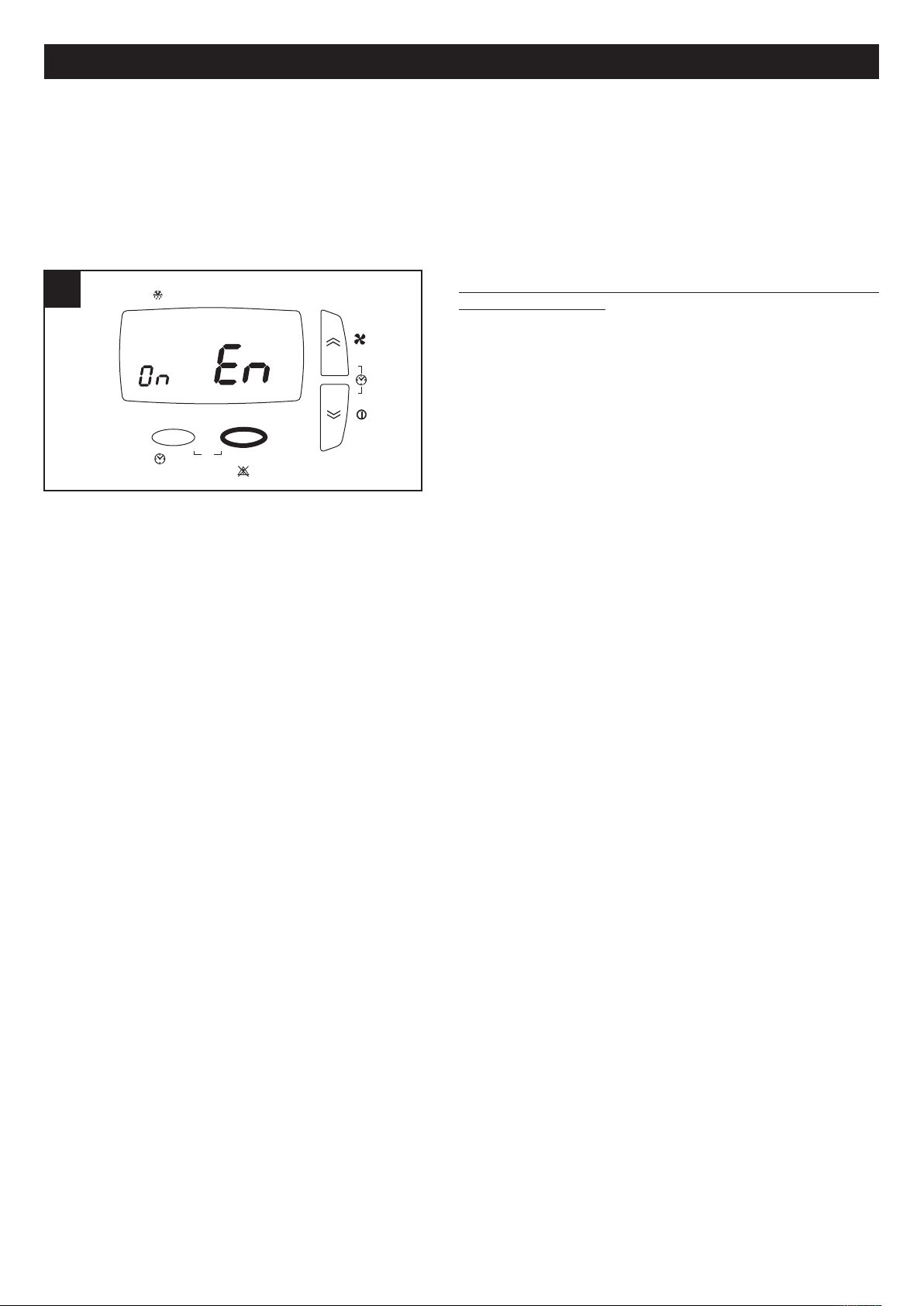
esc set
By-Pass
/ °C
1234567
FILT
P2
P
rg
25 25
P1
HA
MAGYAR
- PROF (csak az Egyesült Királyságon kívüli országokban): működési beállításai profil időpontokkal:
A P1-gyel az egy nap alatti működési intervallumot programozhatja, kezdő időponttal, befejező időponttal és sebességgel;
A P2-vel az egy nap alatti két működési intervallumot programozhatja, kezdő időponttal, befejező időponttal és
sebességgel.
hét minden napjához rendelhet másik profilt.
A
- HA: beállítások HA működéssel: csak HA modullal felszerelt berendezéseken elérhető;
- SERV: szerviz (a telepítőnek fenntartott opció)
PROF opció (csak az Egyesült Királyságon kívüli
országok) (25. ábra)
Ha kiválasztja a PROF opciót a SET gombbal, akkor a profilok
időpont beállításba lép. A paraméterek a következők:
- En (Enable): a lehetséges értékek:
ON: a profilok működését engedélyezi (és a fentiek
szerint automatikusan kikapcsol az esetleges működés HA
módban)
OFF: a profilok működését kapcsolja ki.
Ha az EN ON lett kiválasztva, akkor a következő
paramétereket is be lehet kapcsolni:
- ST: P1 profil intervallum időpont kezdete
- END: P1 profil intervallum időpont vége
- ST1: P2 profil 1. intervallum időpont kezdete
- EN1: P2 profil 1. intervallum időpont vége
- ST1: P2 profil 2. intervallum időpont kezdete
- EN1: P2 profil 2. intervallum időpont vége
- MON: profil társítása hétfőhöz: a lehetséges értékek P1 és P2
- TUE: profil társítása keddhez: a lehetséges értékek P1 és P2
- UED: profil társítása szerdához: a lehetséges értékek P1 és P2
- THR: profil társítása csütörtökhöz: a lehetséges értékek P1 és P2
- FRY: profil társítása péntekhez: a lehetséges értékek P1 és P2
- SAT: profil társítása szombathoz: a lehetséges értékek P1 és P2
- SUN: profil társítása vasárnaphoz: a lehetséges értékek P1 és P2
34
Page 35

esc set
By-Pass
/ °C
1234567
FILT
P2
Prg
26 26
P1
HA
esc set
By-Pass
/ °C
12345
6
7
FILT
P1 P2
Prg
27 27
HA
MAGYAR
pció HA (26. ábra)
O
Az opció csak HA modullal felszerelt modelleknél elérhető
Ha kiválasztja a HA opciót a SET gombbal, akkor a HA mód
beállításba lép. A paraméterek a következők:
En (Enable): a lehetséges értékek:
PROF: a HA módot aktiválja profilokkal
ON: a HA folyamatos módot aktiválja
OFF: kikapcsolja a HA módot
HOL: HOLIDAY módot aktiválja: két órányi antibakteriális
m
készenlét. Ha az EN PROF lett kiválasztva, akkor a
következő paramétereket is be lehet kapcsolni:
- ST: P1 profil intervallum időpont kezdete
- END: P1 profil intervallum időpont vége
- ST1: P2 profil 1. intervallum időpont kezdete
- EN1: P2 profil 1. intervallum időpont vége
- ST1: P2 profil 2. intervallum időpont kezdete
- EN1: P2 profil 2. intervallum időpont vége
- MON: profil társítása hétfőhöz: a lehetséges értékek P1 és P2
- TUE: profil társítása keddhez: a lehetséges értékek P1 és P2
- UED: profil társítása szerdához: a lehetséges értékek P1 és P2
- THR: profil társítása csütörtökhöz: a lehetséges értékek P1 és P2
- FRY: profil társítása péntekhez: a lehetséges értékek P1 és P2
- SAT: profil társítása szombathoz: a lehetséges értékek P1 és P2
- SUN: profil társítása vasárnaphoz: a lehetséges értékek P1 és P2
űködés naponta, két óra levegőfrissítés, 20 óra
Riasztások menü megjelenítése (27. ábra)
Az alábbiakban megadott lépések végrehajtása előtt nyomja
meg az ESC gombot a kilépéshez és a kezdőmenübe
lépéshez.
A riasztások jelzése esetleg a következőképpen történhet:
--nyomja meg hosszan a BEÁLLÍTÁS gombot
--nyomja meg röviden a FEL vagy LE gombot, hogy a
RIASZTÁS menü megjelenjen
--nyomja meg röviden a BEÁLLÍTÁS gombot, hogy
megjelenítse az aktív hibakódot
A rendszer különböző riasztási helyzeteket mutat, amelyek a
felhasználói panelen az alábbiak szerint jelennek meg:
ti: belső hőmérséklet érzékelő hibás; kérje a Műszaki
ügyfélszolgálat segítségét;
tout: külső hőmérséklet érzékelő hibás; kérje a Műszaki
ügyfélszolgálat segítségét;
te: ürítő hőmérséklet érzékelő hibás; kérje a Műszaki ügyfélszolgálat segítségét;
preh: előmelegítő hiba vagy nincs jelen (ha előírt); kérje a Műszaki ügyfélszolgálat segítségét;
Hito: a külső hőmérséklet 45°C-nál nagyobb; kérje a Műszaki ügyfélszolgálat segítségét;
Hiti: a belső hőmérséklet 45°C-nál nagyobb; kérje a Műszaki ügyfélszolgálat segítségét;
Filt: cserélje ki a tele szűrőket (3 hónap). A szűrőcsere után a felhasználó visszaállítható: ehhez elég, ha egyszerre hosszan
megnyomja a FEL és LE gombokat.
Jól jegyezze meg! A kézi visszaállítású hibákat a FEL és LE gombok hosszú megnyomásával állíthatja vissza.
35
Page 36

28 28
29 29
1
2
3
MAGYAR
Karbantartás és tisztítás
ármilyen folyamat megkezdése előtt ellenőrizze, hogy a
B
termék legyen leválasztva az elektromos hálózatról. A
leszerelés és a 28 hozzátartozó felszerelés különleges
karbantartási műveletek és szakképzett személyzet végezze.
Jól jegyezze meg! Az ajtó nyitása előtt hajtsa ki az elülső
iztonsági csavarokat. (28. ábra)
b
űrők
Sz
A karbantartáshoz javasolt idők: Általában a telepítés földrajzi
területétől függően a levegő szennyezettségi szintje változó
és ezért a szűrők élettartama is változik. Ha szem előtt tartja
ezeket a megfigyeléseket, akkor a szűrőkarbantartás idejét
az alábbiak szerint lehet beállítani:
Szűrővizsgálat: 50/60 naponként;
szűrőcsere: 3 vagy 12 havonta (csak az Egyesült
Királyságban), 3 vagy 24 hónap (csak az Egyesült Királyságon kívüli országokban) (a telepítő telepítési fázisában
beállítottól függően) a képernyőn megjelenik egy előzetes riasztás, amely a felhasználót értesíti, hogy a szűrőket ki kell
cserélni. Ettől a pillanattól kezdve a szűrőket 3 havonta kell cserélni (Egyesült Királyságban), 2 havonta (csak az Egyesült
Királyságon kívüli országokban); az időtartam lejárta után a berendezés leáll (Egyesült Királyságban) és a teli szűrő
riasztás kapcsol be (Filt). A hiba visszaállításával (a „Riasztások menü megjelenítése” bekezdésben) a számlálót is
visszaállíthatja.
Jól jegyezze meg! A szűrők hiányos tisztítása és cseréje komolyan befolyásolja a berendezés hatékonyságát:
- nő a levegőkör terhelési vesztesége és csökken a léghozam;
- ebből kifolyólag csökken a gép teljesítménye és a környezeti kényelem.
Jól jegyezze meg! A tele szűrők helyzete a berendezés leállásának leggyakoribb oka: (Filt)
Szűrők kihúzása: 29. ábra
36
Page 37

La Vortice Elettrosociali S.p.A. si riserva il diritto di apportare tutte le varianti migliorative ai prodotti in corso di vendita.
Vortice Elettrosociali S.p.A. reserves the right to make improvements to products at any time and without prior notice.
La société Vortice Elettrosociali S.p.A. se réserve le droit d'apporter toutes les variations afin d'améliorer ses produits en cours de commercialisation.
Die Firma Vortice Elettrosociali S.p.A. behält sich vor, alle eventuellen Verbesserungsänderungen an den Produkten des Verkaufsangebots vorzunehmen.
Vortice Elettrosociali S.p.A. se reserva el derecho de incorporar todas las mejoras necesarias a los productos en fase de venta.
VORTICE ELETTROSOCIALI S.p.A. VORTICE FRANCE VORTICE LIMITED
Strada Cerca, 2- frazione di Zoate 15-33, Rue Le Corbusier Beeches House-Eastern Avenue
20067 TRIBIANO (MI) Europarc - CS 30007 Burton on Trent
Tel. +39 02-90.69.91 94046 Creteil Cedex DE 13 0BB
ITALIA Tel. +33 1-55.12.50.00 Tel. +44 1283-49.29.49
vortice-italy.it FRANCE UNITED KINGDOM
postvendita@vortice-italy.com vortice-france.com vortice.ltd.uk
contact@vortice-france.com sales@vortice.ltd.uk
VORTICE LATAM S.A. VORTICE VENTILATION SYSTEM (CHANGZHOU) CO.LTD
3er Piso, O
cina 9-B, Edi cio Building 19, No.388 West Huanghe Road, Xinbei District,
Meridiano Changzhou, Jiangsu Province CAP:213000
Guachipelin, Escazú, San José CHINA
PO Box 10-1251 vortice-china.com
Tel +506 2201 6242; vortice@vortice-china.com
COSTA RICA
vortice-latam.com
info@vortice-latam.com
MAGYAR
ontos információ a környezetvédelemnek megfelelő ártalmatlanításhoz
F
AZ EURÓPAI UNIÓ NÉHÁNY ORSZÁGÁBAN EZ A TERMÉK NEM TARTOZIK A RAEE IRÁNYELV
NEMZETI TÖRVÉNYEI ALÁ ÉS EZÉRT AZ ÉLETTARTAMA VÉGÉN NEM SZÜKSÉGES SZELEKTÁLT HULLADÉKGYŰJTŐKBE VINNI.
Ez a termék megfelel az 2002/96/EK EU-irányelvnek.
A berendezésen látható áthúzott szemétgyűjtő szimbólum azt jelzi, hogy a terméket az
élettartama végén a háztartási hulladéktól szétválasztva kell leselejtezni, elektromos és
elektronikus készülékeknek fenntartott szelektív hulladékgyűjtő központba kell szállítani,
vagy vissza kell adni a viszonteladónak egy egyenértékű termék vásárlása alkalmával.
A felhasználó felelős az eszköz megfelelő gyűjtőhelyén történő helyes leselejtezéséért, a szemétlerakásra vonatkozó érvényben levő büntetés értelmében megbüntethető.
A nem használható készülék újrahasznosításának, kezelésének és környezeti szempontból kompatibilis ártalmatlanításának céljából megvalósuló, szelektív hulladékgyűjtés hozzájárul a környezetre és
az egészségre kifejtett, esetleges negatív hatások elkerüléséhez és elősegíti a készüléket alkotó alapanyagok újrahasznosítását.
Az elérhető szelektív hulladékgyűjtő rendszerekre vonatkozó további részletekhez keresse fel a helyi
szolgáltatót vagy a boltot, ahol a terméket megvásárolta.
A gyártók és importőrök kötelesek felelősséget vállalni az újrafeldolgozásért és a környezetnek
megfelelő ártalmatlanításért, közvetlenül és közös rendszerben részvétellel.
37
Page 38

Note
38
Page 39

Note
39
Page 40

Note
40
Page 41

41
Page 42

A
TAGL I ANDO INT E RVEN T O I N GA R ANZI A
CERTIFICATE OF WORK PERFORMED UNDER GUARANTEE
COUPON INTERVENTION SOUS GARANTIE
DATA INTERVENTO
DATE OF WORK - DATE INTERVENTION
TIMBRO CENTRO ASSISTENZA
STAMP OF TECHNICAL ASSISTANCE CENTRE - CACHET SERVICE APRES-VENTE
TAGL I ANDO INT E RVEN T O I N GA R ANZI A
CERTIFICATE OF WORK PERFORMED UNDER GUARANTEE
COUPON INTERVENTION SOUS GARANTIE
DATA INTERVENTO
DATE OF WORK - DATE INTERVENTION
TIMBRO CENTRO ASSISTENZA
STAMP OF TECHNICAL ASSISTANCE CENTRE - CACHET SERVICE APRES-VENTE
TAGL I ANDO INT E RVEN T O I N GA R ANZI A
CERTIFICATE OF WORK PERFORMED UNDER GUARANTEE
COUPON INTERVENTION SOUS GARANTIE
DATA INTERVENTO
DATE OF WORK - DATE INTERVENTION
TIMBRO CENTRO ASSISTENZA
STAMP OF TECHNICAL ASSISTANCE CENTRE - CACHET SERVICE APRES-VENTE
TAGL I ANDO INT E RVEN T O I N GA R ANZI A
CERTIFICATE OF WORK PERFORMED UNDER GUARANTEE
COUPON INTERVENTION SOUS GARANTIE
DATA INTERVENTO
DATE OF WORK - DATE INTERVENTION
TIMBRO CENTRO ASSISTENZA
STAMP OF TECHNICAL ASSISTANCE CENTRE - CACHET SERVICE APRES-VENTE
B
C
D
Page 43

ITALIA
Spedire la garanzia in busta
chiusa a:
Vorti ce Elettros oc iali S. p.A.
Strada Cerca 2
Frazione di Zoate
20067 Tribiano Milano
OTHER COUNTRIES
Please send the guarantee to
the retailer’s address in the
country where the appliance
has been purchased.
Autorizzo la Vortice
Elettrosociali S.p.A.
adinserire i miei dati
nelle sue liste e a
comunicarli a terzi
per l’invio di materiale
pubblicitario ed
informativo. In ogni
momento, a norma
dell’art. 13 legge
675/96,potròavere
accesso ai miei dati,
chiederne la modi
ca
olacancellazione
oppure oppormi al
loro utilizzo scrivendo
aVortice
Elettrosociali S.p.A.
Responsabile
trattamento dati Strada Cerca, 2 Frazione di Zoate 20067 Tribiano (MI).
Non autorizzo
(barrare se interessa).
Idonotauthorize
(please tick if
required).
IauthorizeVortice
Elettrosociali S.p.A.
and its local
distributors to include
my personal details
within their database
and they can use it
through a third party
for the despatch of
advertising material.
At any time, in
accordance with the
regulations in force
within my country. I
can have access to
details and can ask to
make changes, or
prohibit the usage of
my details.This will be
done by addressing
my request directly to
the headquarters of
the local distributor
where the appliance
has been bought.
UK-IRELAND
Send the guarantee
in sealed envelope to:
Vorti ce Limite d
Beeches House
Eastern Avenue
Burton on Trent
DE13 0BB United Kingdom
IauthorizeVortice
Ltd. to include my
personal details
within their database,
which they use, via a
third party for the
despatch of
advertising material,
at any time, in
accordance
with the regulations in
force within my
country.
Icanhaveaccess
to my details and can
request changes, or
prohibit the usage of
my details.This will be
done by addressing
my request directly to
Vorti ce Limited
Beeches House
Eastern Avenue
Burton on Trent
DE13 0BB United
Kingdom.
Idonotauthorize
(please tick if
required).
FRANCE
Expédier la garantie sous
enveloppe cachetée a:
Vorti ce France
15-33, Rue Le Corbusier Europarc - CS 30007
90046 CRETEIL CEDEX
Conformément à la
loi informatique et
liberté art. 27 du
27/01/78, vous
disposez d’un droit
d’accés et de
recti
cation des
donné es vous
concernant auprès de
Vorti ce France - 72,
Rue Baratte - Cholet94106 Saint Maur
Cedex.
Par notre
intermédiaire,
votre adresse pourra
être transmise à
des tiers.
Sauf opposition de
votre part (auquel cas
cochez la case ci
dessus).
ITALIA
CONDIZIONI DI GARANZIA
V
ORTICE SPA garantisce i suoi prodotti per
24 mesi dalla data dell’acquisto che deve
essere comprovata da idoneo documento
scale (scontrino o fattura) rilasciato dal
venditore. Nel suddetto periodo di garanzia
V
ORTICE SPA si
i
mpegna, dopo aver effettuato le opportune
valutazioni tecniche, a riparare o a
s
ostituire, gratuitamente, le parti
dell’apparecchio che risultassero affette da
d
ifetti di fabbricazione. La presente
garanzia, da attivare nei modi e nei termini
di seguito indicati, lascia impregiudicati i
diritti derivanti al consumatore dalla
applicazione del D. lgs. 24/2002.Tali diritti,
conformemente alla legge, potranno essere
fatti valere esclusivamente nei confronti del
proprio venditore. La presente garanzia è
valida su tutto il territorio italiano.
M
odalitàecondizionidiattivazionedella
g
aranzia
G
li interventi in garanzia (riparazioni o
sostituzioni del prodotto ovvero delle parti
d
ifettose) saranno eseguiti presso uno dei
Centri di Assistenza Tecnica autorizzati da
V
ORTICE il cui indirizzo è disponibile
sull’elenco telefonico alfabetico o
contattando il numero verde 800.555.777.
La prestazione eseguita in garanzia non
prolunga il periodo della garanzia. Pertanto,
incaso di sostituzione del prodotto o di un
suo componente, sul bene o sul singolo
componente fornito in sostituzione non
decorre un nuovo periodo di garanzia ma si
deve tener conto della data di acquisto del
prodotto originario.
UK AND IRELAND
CONDITIONS OF WARRANTY
This guarantee is offered as an extra
bene
tanddoesnotaffectyourlegal
r
ights. All electrical appliances produced
by Vortice are guaranteed by the
Company for two years against faulty
material or workmanship.
If any part is found to be defective in this
way within the
rst twenty months four
from the date of purchase or hire
purchase agreement, we or our
authorised service agents, will replace or
at our option repair that part without any
charge for materials or labour or
transportation, provided that the
appliance has been used only in
accordance with the instructions
p
rovided with each appliance and has
b
een not connected to an unsuitable
e
lectricity supply, or subjected to misuse,
n
eglect or damage or modi
e
dor
r
epaired by any person not authorised by
us.The correct electricity supply voltage
is shown on the rating plate attached to
the appliance.
This guarantee is normally available only
to the original purchaser of the appliance,
but the Company will consider written
applications for transfer.
Should any defect arise in any Vortice
product anda claim under guarantee
become necessary, the appliance should
be carefully packed and returned to your
approved Vortice stockist.This portion of
the guarantee should be attached to the
appliance.
FRANCE
CONDITIONS DE GARANTIE
Votre appa reil es t couvert par notre garant ie à
condition qu’il ne soit pas utilisé à des
ns autres
que celles dé nies dans nos ches techniques.
Il est garanti pendant deux ans pour l’ensemble
des pièces qui le compose, contre tout vice de
fabrication ou défaut de matiére,
et ce, dès la date de la première mise en service
C
ette garantie s’applique au remplacement gratuit
ou à la réparation sans frais des pièces reconnues
défectueuses par nos services; elle ne peut, en
aucun cas, donner lieu à des dommages et
intèréts.
L
es frais de transport restant à la charge de
l
’utilisateur, et le material voyage à ses risques et
perils.
La garantie sera sans effet si:
•L’appareilasubiundémontage,un
remplacement, de piéce ou une réparation hors
de nos ateliers.
•S’ilaétésurvolté.
•
S’il a été utilisé dans une atmosphére
corrosive.
•S’ilaétédeterioréoubriséparaccident(choc
ou chute....) ou même pendant le transport (le
transporteur est seul responsable).
•Lagarantienes’appliquepassurlespiecesà
durée de vie limitée, (
ltre charbon, charbon
pour collecteur etc....)
En cas de panne. N’écrivez pas, mais retournez
directement l’appareil soigneusement emballé à
notre service après vente voir coordonnées sur
www.vortice-france.com ou au 01.55.1250.00.
Joindre à l’envoi: le présent certi
cat de garantie
validé par le vendeur, accompagné d’une note
explicative succinte.
Page 44
A
NNI
YEARS
2
ANNI
YEARS
2
DATI UTENTE / CUSTOMER DATA / COORDONNÉES DE L’UTILISATEUR
nome /name/nom______________________________________________
cognome /surname/prenom_________________________________
via /street/rue __________________________________________________
cap /postcode/codepostal _____________________________________
città /town______________________________________________________
TIMBRO RIVENDITORE
stamp of supplier
cacher du vendeur
2
GARANZIA - GUARANTEE - GARANTIE
DA SPEDIRE
(entro 8 giorni dall’acquisto)
TO SEND (within 8 days from date of purchase)
ARETOURNER(dansles8joursaprèsl’achat)
P
er poter usufruire della garanzia il cliente deve compilare e rispedire alla VORTICE
S
PA, entro 8 giorni d all’acq uis to, la “Parte 2”deltagliandodigaranzia,all’indirizzo
e
conlemodalitàintaleparteriportate.
L
a“Parte 1”deltagliandodigaranziadeveessereconservataepresentata,
u
nitamente al documento
s
cale (scontrino o fattura) rilasciato dal venditore al
m
omento dell’acquisto, al Centro di Assistenza autorizzato VORTICE che dovrà
e
seguire l’intervento in garanzia.
T
his warranty must be attached to the appliance should it need to be returned for
s
ervicing.
N
.B. Guarantee is only valid if all details are completed correctly.
A
TTENTION: pour béné
c
ier de la garantie, le présent certicat doit obligatoirement
a
ccompagner l’appareil présumé défectueux. Le certi
c
at doit porter le cachet du
revendeur et la date d’achat.
Adefaut,lagarantieseracomptéeàpartirdeladatedesortied’usine.
GARANZIA - GUARANTEE - GARANTIE
DA CONSERVARE
TO BE RETAINED
ACONSERVER
E
sclusioni
La presente garanzia non copre:
•Lerottureprovocatedaltrasporto.
•Idifettioguastiderivantidausononcorrettooimpropriodapartedelcliente.
•Idifettiderivantidalmancatorispettodelleavvertenzeecondizionid’uso
i
ndicate nel libretto di istruzioni ed uso allegato al prodotto.
•Idifettiderivantidanoncorrettainstallazioneovverodaunainstallazione
e
ffettuata senza rispettare quanto previsto nel relativo capitolo del libretto di
i
struzioni ed uso.
•Iguastiderivantidaunerratoallacciamentoallaretedialimentazioneelettricaopertensionedialimentazionediversadaquellaprevistaper
l’apparecchio, ovvero diversa dal limite stabilito dalle norme CEI (+/- 10% del valore nominale).
La presente garanzia non copre, inoltre, gli eventuali difetti derivanti da una cattiva manutenzione ovvero da interventi effettuati da personale non
quali
cato o da terzi non autorizzati.
1
Dichiaro di aver preso atto delle condizioni di garanzia speci cate sul certi cato in mio possesso e autorizzo la gestione dei miei dati personali (v. retro).
IhavereadandunderstoodthetermsandconditionsofthisguaranteeandIauthorisetheprocessingofmypersonaldetails(seeoverleaf).
Suivant les conditions de garantie dé
nies par le certi cat en ma possession j’autorise l’utilisation de mes coordonnées (voir au verso).
rma / signature / signature _________________________________
DATA
DATA - DATE
A
NNI
YEARS
2
ANNI
YEARS
2
SPEDITO IL
MAILING DATE - ENVOYÉ PAR LA POSTE LE
CONF.
----------------COLL.
TIMBRO RIVENDITORE
stamp of supplier
cacher du vendeur
SPEDITO IL
MAILING DATE - ENVOYÉ PAR LA POSTE LE
ACQUISTATO IL
DATE OF PURCHESE - DATE DE L’ACHAT
DATA
DATA - DATE
 Loading...