

Page 1
Libretto istruzioni
Instruction booklet
VORT HR 200 BP
COD. 5.471.084.839
27/02/2018
Page 2

Prima di installare ed utilizzare il prodotto, leggere
attentamente le istruzioni contenute nel presente
libretto. Vortice non potrà essere ritenuta
responsabile per eventuali danni a persone o cose
ausati dal mancato rispetto delle indicazioni di
c
seguito elencate, la cui osservanza assicurerà
invece la durata e l’affidabilità, elettrica e
meccanica, dell’apparecchio. Conservare perciò
sempre questo libretto d’istruzioni.
Before installing and using your product, read
these instructions carefully. Vortice will not accept
any responsibility for damage to property or
personal harm resulting from failure to abide by
the conditions listed below.
Following these instructions will ensure long
service life and overall electrical and mechanical
reliability. Keep this instruction booklet in a safe
place for reference purposes.
Indice IT
Descrizione ed impiego . . . . . . . . . . . . . . . . . . . . . . . . . . . . . 3
Garanzia e responsabilità . . . . . . . . . . . . . . . . . . . . . . . . . . . 3
Sicurezza . . . . . . . . . . . . . . . . . . . . . . . . . . . . . . . . . . . . . . . . 4
Struttura e dotazione . . . . . . . . . . . . . . . . . . . . . . . . . . . . . . . 5
ccessori in dotazione . . . . . . . . . . . . . . . . . . . . . . . . . . . . . 5
A
Installazione . . . . . . . . . . . . . . . . . . . . . . . . . . . . . . . . . . . . . 5
Schemi di collegamento . . . . . . . . . . . . . . . . . . . . . . . . . . . 10
Funzionamento . . . . . . . . . . . . . . . . . . . . . . . . . . . . . . . . . . 11
Utilizzo . . . . . . . . . . . . . . . . . . . . . . . . . . . . . . . . . . . . . . . . . 11
Manutenzione/pulizia. . . . . . . . . . . . . . . . . . . . . . . . . . . . . . 20
Informazione importante per lo smaltimento
ambientalmente compatibile . . . . . . . . . . . . . . . . . . . . . . . . 23
Table of Contents EN
Compliance with Building Codes . . . . . . . . . . . . . . . . . . . . 24
Description and operation . . . . . . . . . . . . . . . . . . . . . . . . . . 24
Guarantee and responsibility. . . . . . . . . . . . . . . . . . . . . . . . 24
Safety. . . . . . . . . . . . . . . . . . . . . . . . . . . . . . . . . . . . . . . . . . 25
Items supplied . . . . . . . . . . . . . . . . . . . . . . . . . . . . . . . . . . . 26
Accessories supplied. . . . . . . . . . . . . . . . . . . . . . . . . . . . . . 26
Installation . . . . . . . . . . . . . . . . . . . . . . . . . . . . . . . . . . . . . . 26
Electrical connections . . . . . . . . . . . . . . . . . . . . . . . . . . . . . 31
Function. . . . . . . . . . . . . . . . . . . . . . . . . . . . . . . . . . . . . . . . 32
Use . . . . . . . . . . . . . . . . . . . . . . . . . . . . . . . . . . . . . . . . . . . 32
Maintenance/cleaning . . . . . . . . . . . . . . . . . . . . . . . . . . . . . 41
Building Regulations Document F1 2006 . . . . . . . . . . . . . . 44
Important information regarding
eco-compatible disposal . . . . . . . . . . . . . . . . . . . . . . . . . . . 45
2
Page 3

ITALIANO
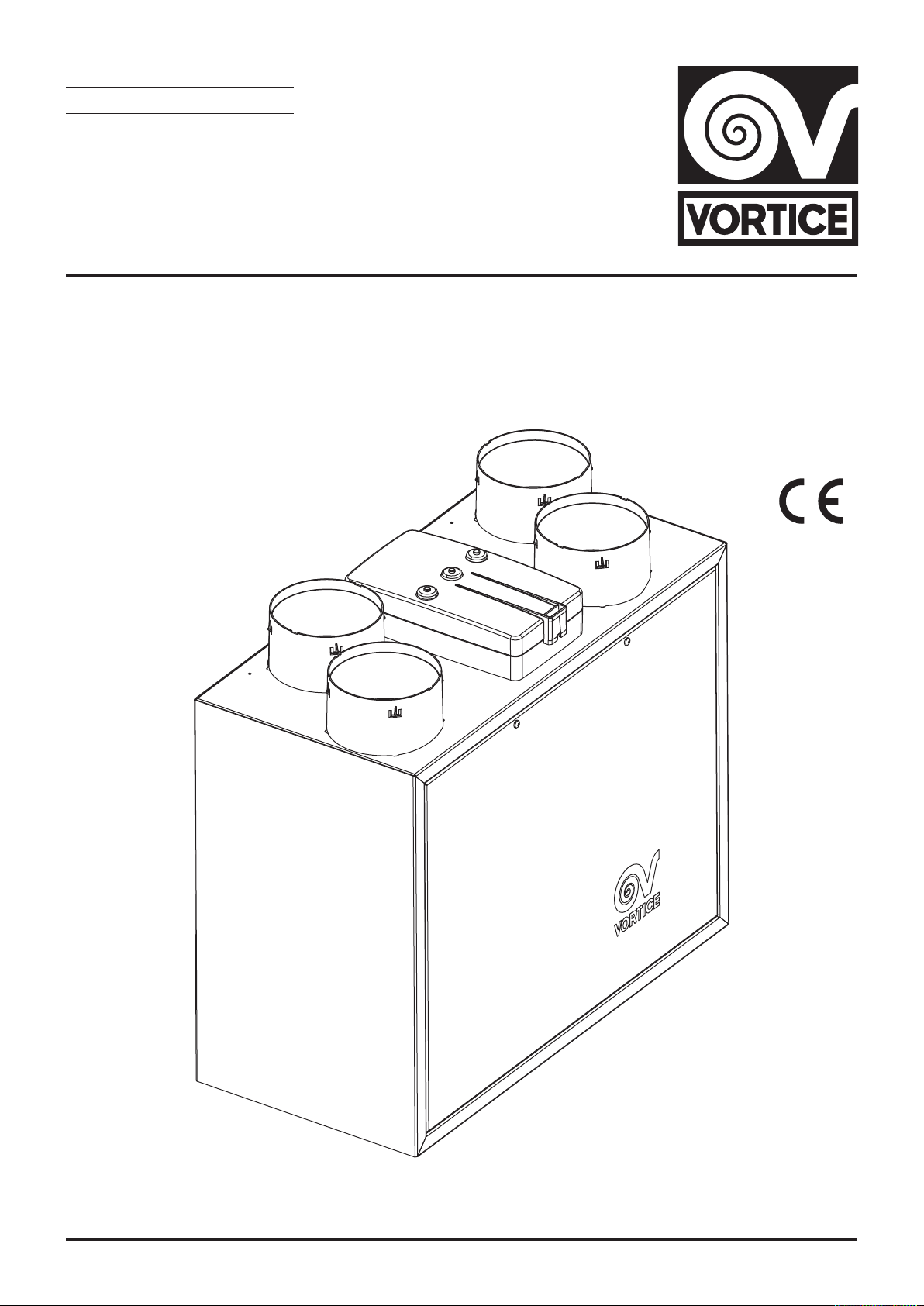
Descrizione ed Impiego
ORT HR 200 BP (nel seguito “l’apparecchio”), è un
V
sistema di ventilazione centralizzato a recupero di calore
ad elevatissima efficienza, installabile in posizione
verticale tramite i ganci in dotazione oppure in posizione
orizzontale per mezzo di apposito kit opzionale.
el normale funzionamento l’aria viziata viene estratta
N
dai locali di servizio quali la cucina, le stanze da bagno,
le stanze di servizio e le dispense;
contemporaneamente, aria fresca esterna viene
immessa nelle stanze normalmente abitate, come le
camere da letto, gli studi ed i soggiorni. Le portate d’aria
necessarie sono quelle espresse dai vigenti regolamenti
nazionali; nel Regno Unito valgono le UK “Building
Regulations Document F1”.
Nel funzionamento normale i volumi totali dell’aria
estratta e dell’aria reimmessa sono sostanzialmente
equivalenti. I flussi d’aria in ingresso ed uscita sono tra
loro perfettamente separati ed adeguatamente filtrati.
Nella stagione fredda il calore dell’aria espulsa viene
trasferito all’aria in ingresso. La condensa creata dal
processo, e che si raccoglie all’interno del prodotto,
deve essere poi convogliata all’esterno.
L’apparecchio garantisce una silenziosa e continua
ventilazione dalla casa, rimuovendo l’aria viziata e
reintegrandola con aria fresca opportunamente filtrata,
prelevata dall’esterno. All’interno dello scambiatore di
calore, che costituisce il cuore dell’apparecchio, si
realizza lo scambio termico tra i 2 flussi, che assicura il
risparmio energetico garantito dall’impiego
dell’apparecchio stesso.
Garanzia e Responsabilità
aranzia
G
La garanzia dell’apparecchio ha validità 2 anni a partire
dalla data di acquisto.
La garanzia non si applica a:
• costi di montaggio/smontaggio;
danni dovuti ad un utilizzo improprio o negligente
•
dell’apparecchio;
• danni causati da riparazioni, o tentativi di riparazioni,
da parte di terze parti non autorizzate da Vortice.
Responsabilità
L’apparecchio è progettato per “sistemi di ventilazione
bilanciata” . Ogni altro utilizzo che non sia stato
preventivamente discusso con un esperto Vortice può
essere considerato come utilizzo improprio. In questo
caso Vortice non potrà essere ritenuta responsabile per
eventuali malfunzionamenti o guasti.
Vortice non si ritiene responsabile per guasti dovuti a:
• utilizzo improprio dell’apparecchio;
• normale usura dell’apparecchio;
• mancato rispetto da parte dell’utilizzatore di quanto
riportato nel presente libretto.
3
Page 4
1 1
A
ITALIANO
Sicurezza
Attenzione:
questo simbolo indica che è necessario
!
prendere precauzioni per evitare danni all’utente
• Seguire le istruzioni di sicurezza per evitare danni
ll’utente.
a
• Non utilizzare l’apparecchio per una funzione
differente da quella esposta in questo libretto.
• Dopo aver tolto il prodotto dal suo imballo assicurarsi
della sua integrità: nel dubbio rivolgersi a persona
professionalmente qualificata o ad un Centro
Assistenza Tecnica autorizzato Vortice.
• Non lasciare parti dell’imballo alla portata di bambini o
persone diversamente abili.
• L’uso di qualsiasi apparecchio elettrico comporta
l’osservanza di alcune regole fondamentali, tra le
quali:
- non toccarlo con mani bagnate o umide;
- non toccarlo a piedi nudi.
• Questo apparecchio non è da intendersi adatto all’uso
da parte di persone (inclusi i bambini) in possesso di
ridotte capacità fisiche, sensoriali o mentali, o prive di
esperienza e conoscenza, a meno che siano
supervisionate o preventivamente istruite riguardo al
suo impiego da persona responsabile della loro
sicurezza. I bambini dovrebbero essere controllati per
assicurarsi che non giochino con l’apparecchio.
• Non utilizzare l’apparecchio in presenza di sostanze o
vapori infiammabili come alcool, insetticidi, benzina,
ecc.
• Riporre l’apparecchio lontano da bambini e persone
diversamente abili, nel momento in cui si decide di
scollegarlo dalla rete elettrica e di non utilizzarlo più.
Avvertenza:
questo simbolo indica che è necessario
!
prendere precauzioni per evitare danni al prodotto
•Non apportare modifiche di alcun genere
all’apparecchio.
• Le istruzioni per la manutenzione devono essere
seguite per prevenire danni e/o usura eccessiva
dell’apparecchio;.
• Non lasciare l’apparecchio esposto ad agenti
atmosferici (pioggia, sole, ecc.).
•Non appoggiare oggetti sull’apparecchio.
• La pulizia interna del prodotto deve essere eseguita
soltanto da personale qualificato.
• Verificare periodicamente l’integrità dell’apparecchio.
In caso di imperfezioni, non utilizzarlo ma contattare
subito un Centro di Assistenza Tecnica autorizzato
Vortice.
• In caso di cattivo funzionamento e/o guasto
dell’apparecchio rivolgersi subito ad un Centro
Assistenza Tecnica autorizzato Vortice e richiedere, per
l’eventuale riparazione, l’uso di ricambi originali
Vortice.
• Se il prodotto cade o riceve forti colpi farlo verificare
subito presso un Centro di Assistenza Tecnica
autorizzato Vortice.
• L’installazione dell’apparecchio deve essere effettuato
a parte di personale professionalmente qualificato.
d
• L’apparecchio deve essere montato in modo da
garantire che, in condizioni normali di funzionamento,
nessuno possa venirsi a trovare in prossimità di parti in
movimento o sotto tensione.
Nel caso di interventi di manutenzione (es. estrazione
•
dello scambiatore di calore), l’apparecchio dovrà
essere preventivamente spento e disconnesso dalla
rete di alimentazione elettrica.
• L’impianto elettrico a cui è collegato il prodotto deve
essere conforme alle norme vigenti.
• Per l’installazione occorre prevedere un interruttore
bipolare con distanza di apertura dei contatti uguale o
superiore a mm 3.
• Collegare l’apparecchio alla rete di
alimentazione/presa elettrica solo se la portata
dell’impianto/presa, è adeguata alla sua potenza
massima. In caso contrario rivolgersi subito a
personale professionalmente qualificato.
• Spegnere l’interruttore generale dell’impianto quando:
- si rileva un’anomalia di funzionamento;
- si decide di eseguire una manutenzione di pulizia
esterna;
- si decide di non utilizzare per brevi o lunghi periodi
l’apparecchio.
• L’apparecchio non può essere utilizzato come
attivatore di scaldabagni, stufe, ecc., nè deve scaricare
nei condotti d’acqua calda di tali apparecchi.
• L’apparecchio deve scaricare direttamente all’esterno,
in un condotto singolo dedicato.
• Il flusso d’aria estratto deve essere pulito, (cioè privo di
elementi grassi, fuliggine, agenti chimici e corrosivi o
miscele esplosive ed infiammabili).
• Non coprire e non ostruire l’aspirazione e la mandata
dell’apparecchio, in modo da assicurare l’ottimale
passaggio dell’aria.
• I dati elettrici della rete devono corrispondere a quelli
riportati in targa A (fig. 1).
4
Page 5
ITALIANO
2 2
3 3
Struttura e Dotazione
e principali parti componenti l’apparecchio sono così
L
riassumibili:
• involucro esterno e coperchio frontale, in lamiera
d’acciaio verniciata; nell’involucro sono integrati i
dispositivi di connessione alle tubazioni di
spirazione/mandata e la scatola dei collegamenti
a
elettrici; l’involucro racchiude inoltre a tenuta i
componenti interni e lo scambiatore di calore;
• convogliatori interni in PPE (polipropilene espanso),
che realizzano la distribuzione dei flussi d’aria
massimizzando l’isolamento termico e minimizzando
le perdite;
• scambiatore di calore, in resina plastica e del tipo a
flussi in controcorrente, la cui particolare morfologia
garantisce un’ elevatissima efficienza di scambio
termico (fino al 93%);
• filtri (2) con grado di ritenzione G3;
• motori brushless (2) abbinati a giranti centrifughe;
• scheda elettronica, che sovraintende
all’alimentazione, al comando ed al controllo
dell’apparecchio;
• 3 sensori di temperatura:
-aria interna;
-aria esterna;
-aria espulsa;
• timer per avviso sostituzione filtri;
• uscita per eventuale collegamento di un preheater
(funzionamento Nofrost).
• collegamento opzionale ad interruttore per velocità
massima (boost).
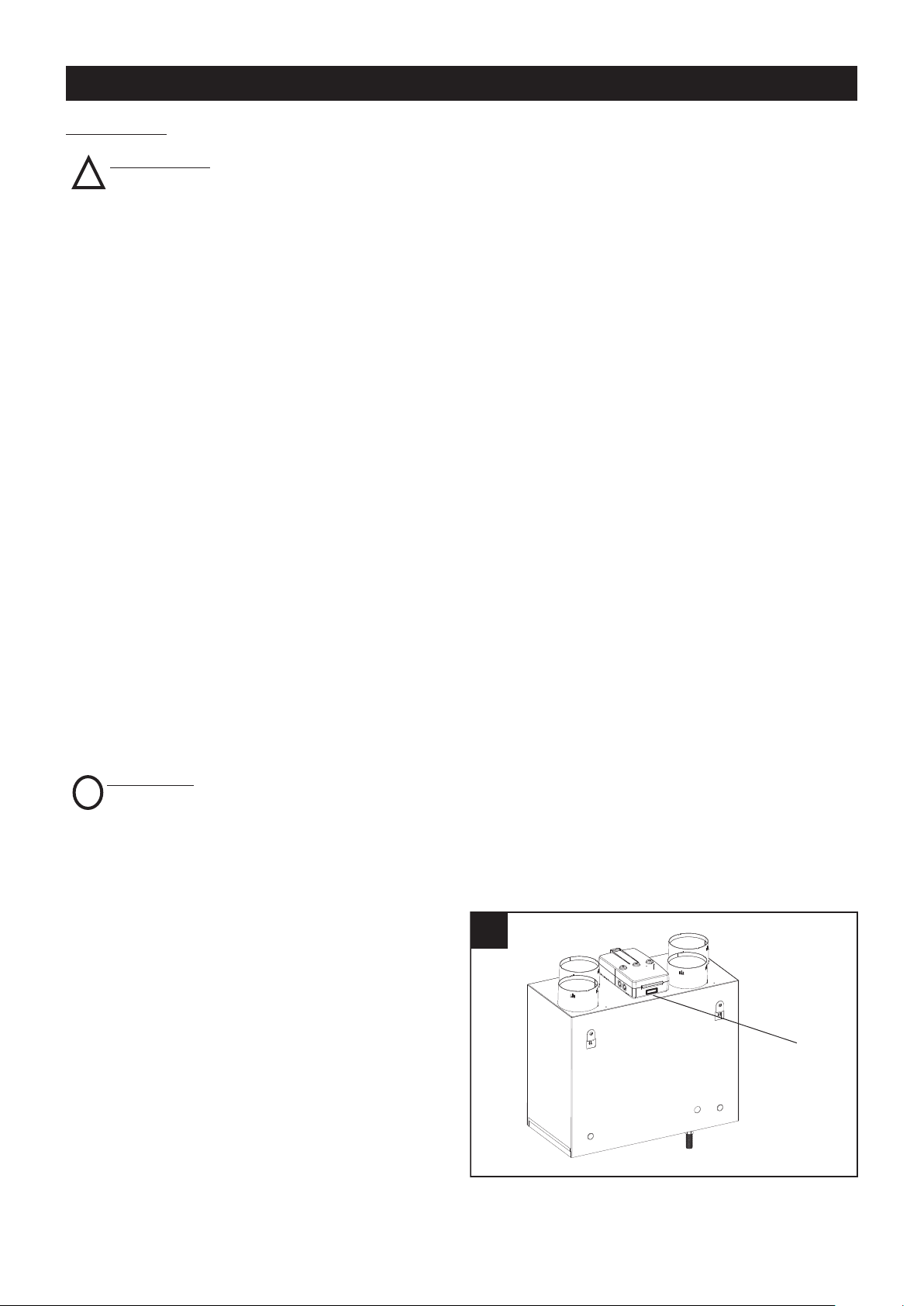
nominale pari a 125 mm, devono essere fissate alle
corrispondenti bocche dell’apparecchio mediante
fascette o altri adeguati sistemi di tenuta.
el corso del normale funzionamento, sul fondo
N
dell’apparecchio si raccoglie condensa per il cui
smaltimento è necessario applicare, in corrispondenza
dell’apposito attacco (fig. 2) , il tubo in dotazione che
consente di far confluire l’acqua in uno scarico (per le
modalità vedere Montaggio).
L’apparecchio deve essere facilmente accessibile nel
caso di interventi di servizio/manutenzione. In
particolare assicurarsi della presenza di uno spazio
libero di almeno 50 cm in corrispondenza del pannello
frontale, per agevolare la pulizia e la sostituzione dello
scambiatore di calore e dei filtri. (fig. 3)
Accessori in Dotazione
La dotazione di serie dell’apparecchio comprende:
• n°1 raccordo per scarico condensa
• n°1 tubo flessibile per scarico condensa;
• n°2 tasselli con gancio per il montaggio a parete
• controllo remoto cablato, con display LCD, tramite il
quale è possibile eseguire il set-up iniziale in fase di
installazione (a cura dell’installatore) e controllare il
funzionamento dell’apparecchio;
Installazione
L’apparecchio deve essere installato seguendo le norme
di sicurezza in vigore nel paese di destinazione e le
istruzioni del presente libretto.
Prerequisiti
L’apparecchio deve essere installato su una superficie o
parete interna all’abitazione e strutturalmente adatta a
reggerne il peso.
I condotti utilizzati per le canalizzazioni devono essere
delle corrette dimensioni.
I condotti da e verso l’esterno devono essere isolati
termicamente e non soggetti a vibrazioni.
Le tubazioni di aspirazione e mandata, di diametro
5
Controlli alla consegna
Controllare l’apparecchio alla consegna per individuare
eventuali difetti prima di procedere alla sua installazione.
Nel dettaglio:
• prima di procedere alla sua estrazione dall’imballo,
controllare che il nome e la descrizione riportati sulla
scatola siano corretti;
• estratto l’apparecchio dall’imballo, verificare che non
siano presenti danni visibili, quindi accertarsi della
presenza del tubetto per lo scarico della condensa e
del libretto istruzioni.
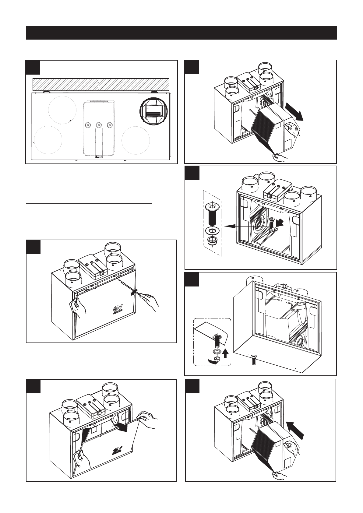
Page 6
ITALIANO
7 7
8 8
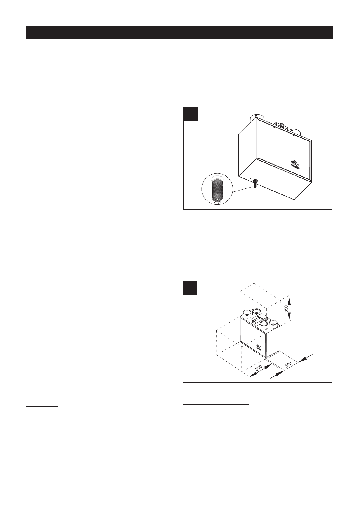
Montaggio
L’apparecchio è equipaggiato con 2 tasselli con gancio
per il montaggio verticale a parete.
Determinare l’esatta posizione di destinazione
ell’apparecchio, tenendo presenti i requisiti per
d
l’installazione.
Montaggio in verticale
Fissare a muro i ganci, seguendo le figure successive.
(fig. 4,5,6,7,8).
4
6
5
6
Page 7
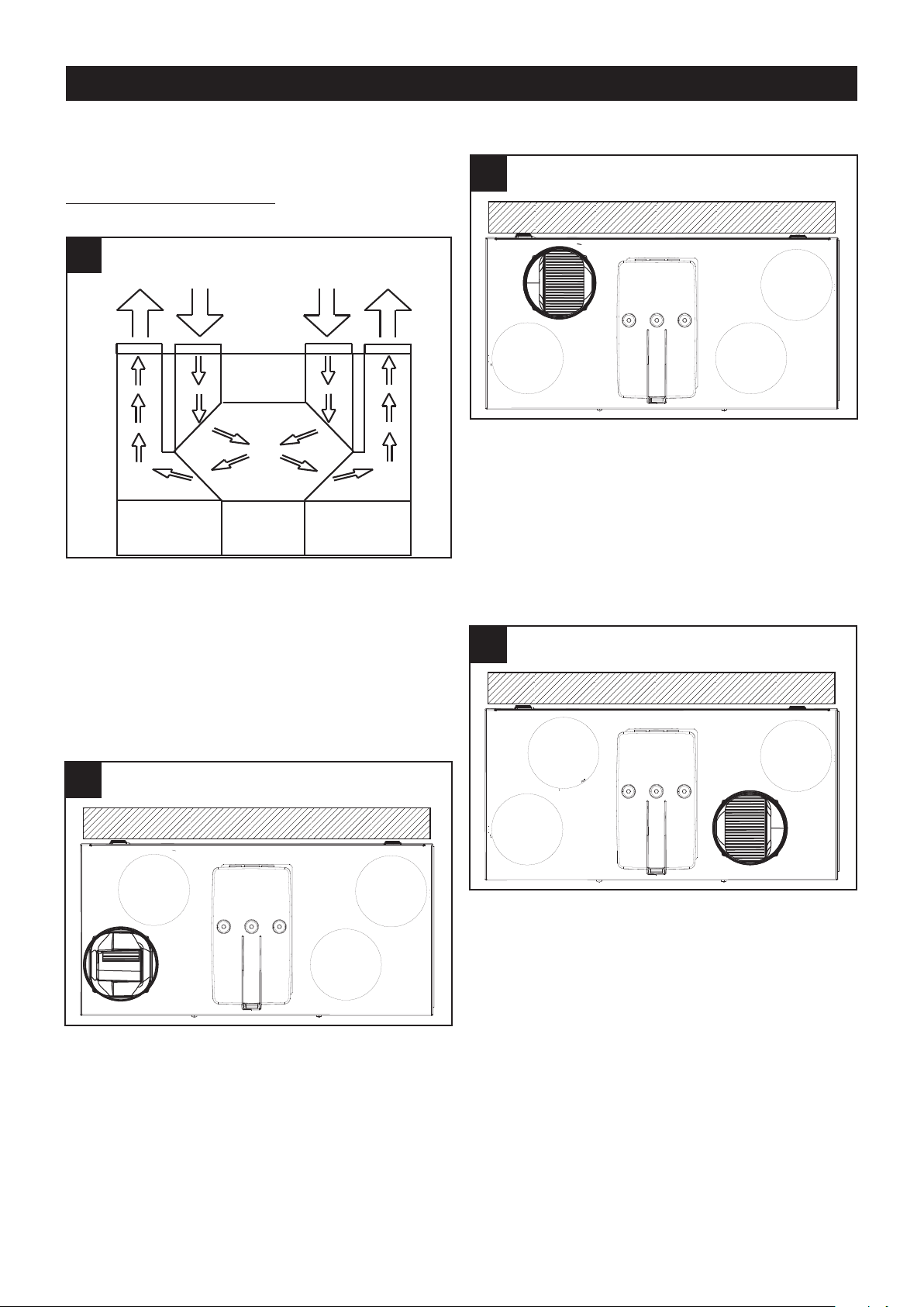
ITALIANO
M
ANDATA
ARIA VIZIATA
V
ERSO
L’ESTERNO
A
SPIRAZIONE
ARIA FRESCA
D
ALL’
ESTERNO
A
SPIRAZIONE
ARIA VIZIATA
D
A
CASA
M
ANDATA
ARIA FRESCA
I
N
CASA
10 10
11 11
12 12
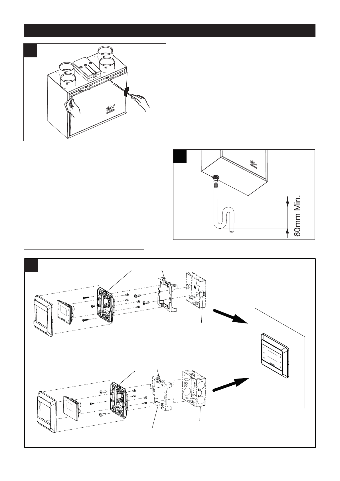
Montaggio in orizzontale (kit opzionale)
L’apparecchio può essere montato in orizzontale tramite
apposito kit opzionale.
onnessione delle tubazioni
C
(fig. 9).
9
Aspirazione aria fresca dall’esterno
(fig. 11)
Questa bocca è utilizzata per l’ingresso dell’aria fresca
dall’esterno; il relativo condotto deve essere isolato
termicamente e provvisto di dispositivi in grado di
smorzare eventuali vibrazioni. Se l’ingresso dell’aria
avviene dal tetto è obbligatorio l’utilizzo di un opportuno
dispositivo inteso ad evitare la formazione di condensa
e l’entrata di acqua piovana.
I raccordi dell’apparecchio hanno diametro nominale
pari a 125 mm. Alle bocche dell’apparecchio possono
essere collegati tubi rigidi o flessibili. Nel seguito ogni
connessione è illustrata da una figura che specifica
anche le direzioni di provenienza e mandata del relativo
flusso d’aria.
Mandata aria viziata verso l’esterno
(fig. 10).
Aspirazione aria viziata da casa
(fig. 12)
Questa bocca è utilizzata per convogliare
nell’apparecchio l’aria viziata estratta dall’interno della
casa. Il condotto richiede isolamento termico.
Questa bocca è utilizzata per espellere all’esterno l’aria
viziata già trattata nello scambiatore di calore. Il
condotto a cui lo scarico va connesso deve essere
termicamente isolato (per evitare la formazione di
condensa sulle sue parti interne ed esterne), e provvisto
di dispositivi per smorzare le eventuali vibrazioni. Se lo
scarico avviene dal tetto è obbligatorio l’utilizzo di un
opportuno dispositivo inteso ad evitare la formazione di
condensa e l’entrata di acqua piovana.
7
Page 8
19 19
ITALIANO
13 13
14 14
15 15
17 17
Mandata aria fresca in casa
(fig. 13)
Questa bocca è utilizzata per immettere all’interno della
casa l’aria fresca esterna, preventivamente trattata nello
scambiatore di calore.
Connessione del tubo di scarico condensa.
Il punto di connessione è posto sul fondo
dell’apparecchio; esso deve essere predisposto
secondo la sequenza qui sotto descritta.(fig.
14,15,16,17,18,19,20)
8
Page 9
ITALIANO
$/72
$/72
121,1'27$=,21(
22 22
83
&2148(67202'(//2',6&$72/$
48(672(/(0(172121'(9((66(5(,167$//$72
121,1'27$=,21(
83
2020
2121
Lo scarico della condensa deve essere realizzato
connettendo il tubo flessibile in dotazione al raccordo
scarico condensa. Per impedire la formazione di bolle
d’aria occorre realizzare con il tubetto un sifone, come
indicato in fig. 21
Montaggio scatola controllo remoto cablato
9
Page 10
ITALIANO
2323
N
L
230V ~ 50Hz
1
PE
G
NYE
BU
BN
B
N
B
U
2
230V ~50Hz
M
AINS
MAINS
PREH
L
N
N
P
REH
1
Mains 2 poles switch
2
P
reheater (remote 230Vac relay coil )
2424
3
4
V
CC
A
B
G
ND
VCC
A
B
GND
GND
BOOST
H
MI
BOOST
3
Dry contact (remote switch / relay )
4
Remote H MI
Schemi di collegamento
10
Page 11
ITALIANO
Funzionamento
otori
M
L’apparecchio è equipaggiato di due motori brushless
studiati per garantire bassissimi consumi, grazie alla
loro elevata efficienza, azionanti due ventole centrifughe
che estraggono l’aria viziata ed umida dai locali di
ervizio (cucine, bagni, lavanderie, ecc.) ed immettono
s
aria fresca esterna nei locali abitativi (soggiorni, sale da
pranzo, camere da letto, ecc.);
Scambiatore di calore
I due flussi d’aria, in ingresso ed uscita, si incontrano
nell’apparecchio (senza peraltro mai venire a contatto
diretto, per non pregiudicare la qualità dell’aria in
entrata), internamente allo scambiatore di calore,
laddove l’aria calda in uscita/ingresso cede calore
all’aria fredda in ingresso/uscita, minimizzando così le
variazioni di temperatura negli ambienti asserviti.
Filtri
Due filtri G3, alloggiati all’interno dei canali di mandata
ed estrazione in prossimità dello scambiatore di calore
ed accessibili rimuovendo il pannello frontale,
salvaguardano l’apparecchio dalle impurità contenute
nell’aria viziata espulsa e prevengono l’immissione di
aria inquinata nei locali asserviti.
Lo stato di occlusione dei filtri può essere monitorato
rimuovendo il pannello frontale ed estraendo i
componenti in questione dalle sedi.
La sostituzione del filtro standard G3 alloggiato nel
canale di immissione dell’aria fresca con un filtro
opzionale F5, assicura superiori capacità filtranti.
Protezione antigelo
Con l’approssimarsi delle condizioni ambientali che
potrebbero favorire la fomazione di brina sulle pareti
dello scambiatore, la scheda elettronica provvede
automaticamente all’adeguamento della velocità dei
ventilatori e delle relative portate d’aria.
Nel corso della procedura di sbrinamento automatico
non sarà possibile all’utente modificare la velocità di
funzionamento dell’apparecchio.
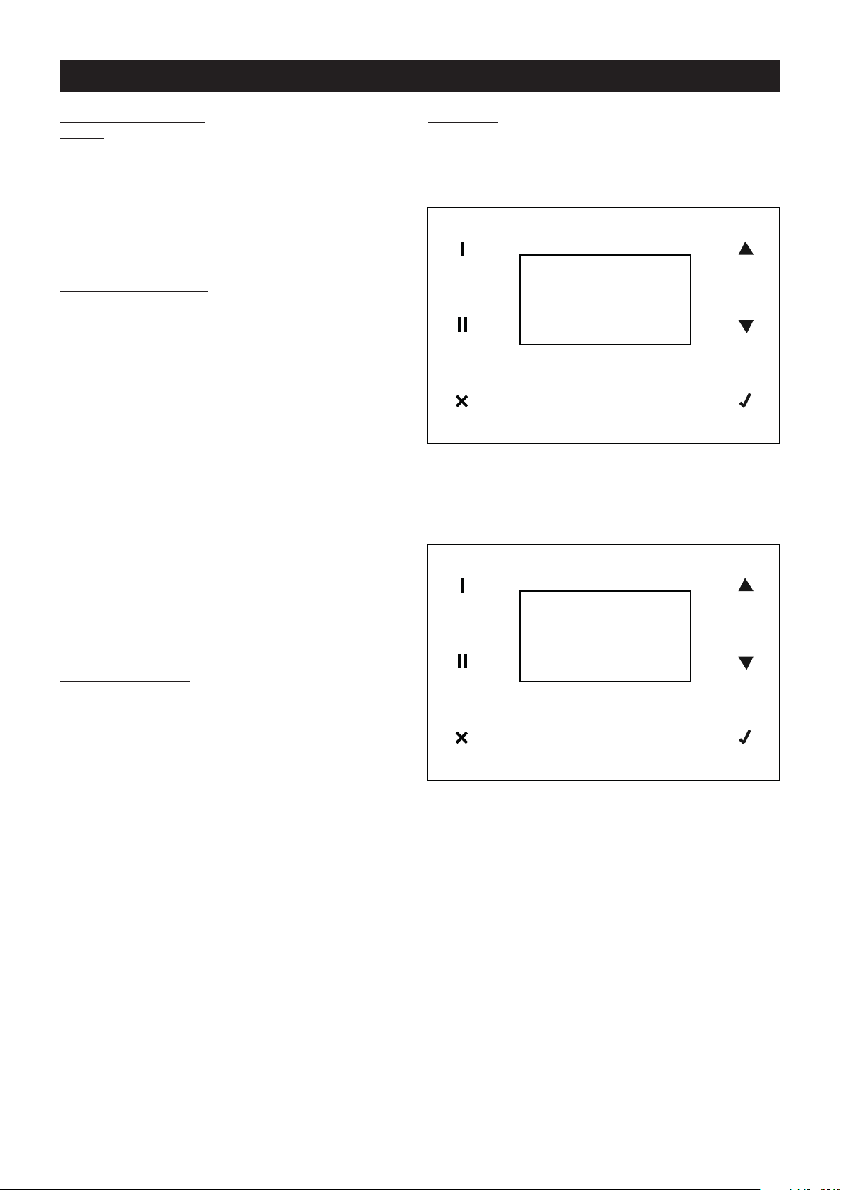
Utilizzo
ENERALITA’
G
L’apparecchio ha un funzionamento in continuo. Tutte le
funzioni sono controllabili tramite un pannello comandi
cablato, dotato di schermo touch:
B
A
A: area touch
B: display
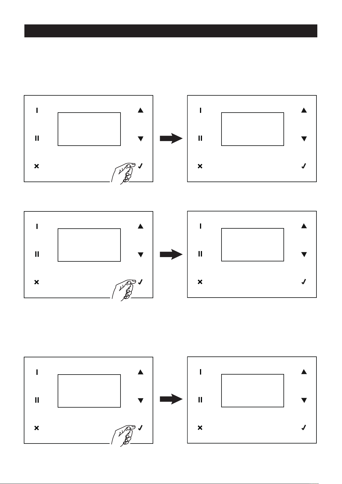
SIGNIFICATO DELLE ICONE/TASTI DELL’AREA TOUCH
1
2
3
1: visualizzazione data/ora (ultima riga display);
2: visualizzazione T int, T ext, T espulsa (ultime due
righe display);
3: uscire senza salvare e tornare alla pagina precedente
4: aumentare la velocità (da Normal a Boost), o spostare
il cursore sulla riga soprastante, o incrementare il
valore;
5: diminuire la velocità (da Boost a Normal), o spostare
il cursore sulla riga sottostante, o decrementare il
valore;
6: confermare la scelta corrente e passare alla pagina
successiva con salvataggio dei dati correnti.
4
5
6
11
Page 12
ITALIANO
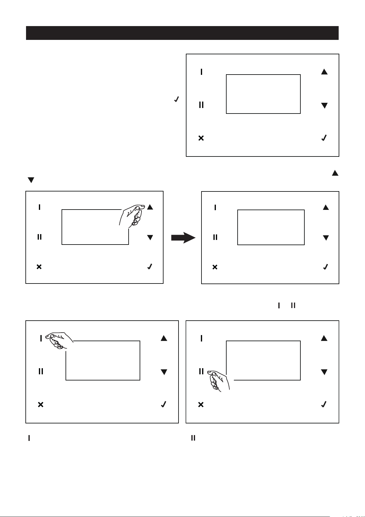
FUNZIONI PANNELLO COMANDI
Alla prima attivazione, a cura dell’installatore, il display
visualizza il logo Vortice e dopo 10 secondi la velocità di
funzionamento preimpostata: NORMAL
N.B. In generale, in mancanza di input utente, dopo due
minuti il display torna alla schermata del logo, senza
salvare eventuali cambiamenti. In tal caso premere
per riattivare la schermata iniziale.
In questa fase è possibile incrementare immediatamente la velocità al valora massimo BOOST, agendo sul tasto
( per diminuire da BOOST a NORMAL).
NORMAL
13 / 01 / 18 08:07
NORMAL
13 / 01 / 18 08:07
E’ possibile variare il tipo di dati visualizzati nella parte bassa del display, utilizzando i tasti e
NORMAL
13 / 01 / 18 08:07
BOOST
13 / 01 / 18 08:07
NORMAL
Ext+19° Int+21°
Exh+21°
: data e ora : temperature: Esterna, Interna, Espulsa
Page 13
ITALIANO
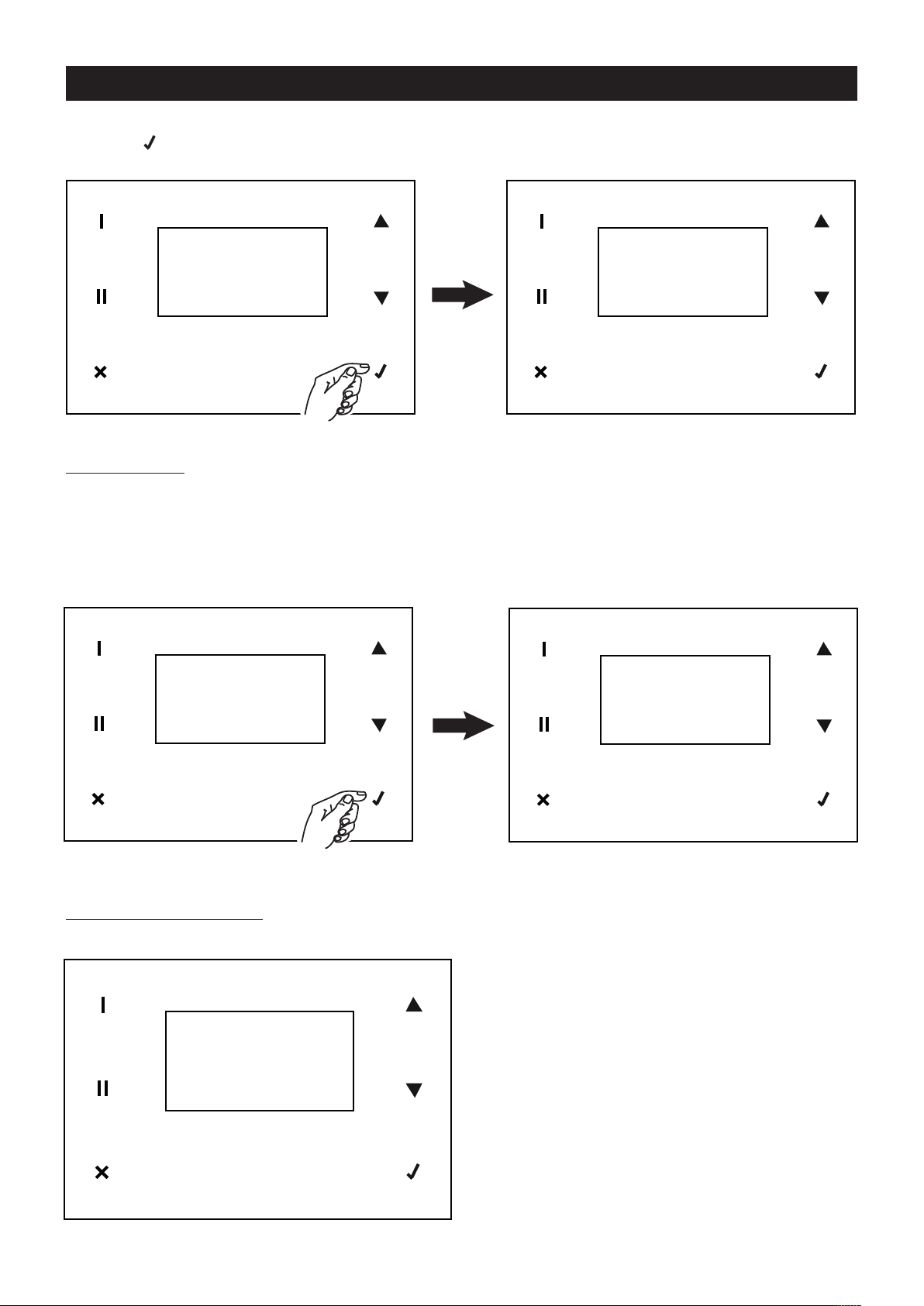
Tutte le altre funzioni sono raggiungibili a partire da un menu principale. Il menu principale si può visualizzare
remendo nella schermata iniziale.
p
MAIN MENU
NORMAL
13 / 01 / 18 08:07
Menu principale
Use menu
Con questa opzione e tramite l’immissione di password nella schermata successiva si può accedere alle
impostazioni di competenza dell’installatore e della fabbrica.
Impostazioni dell’installatore: password: 023
Impostazioni della fabbrica: password non disponibile
USE MENU
ALARM
SETUP
INFO
MAIN MENU
USE MENU
ALARM
SETUP
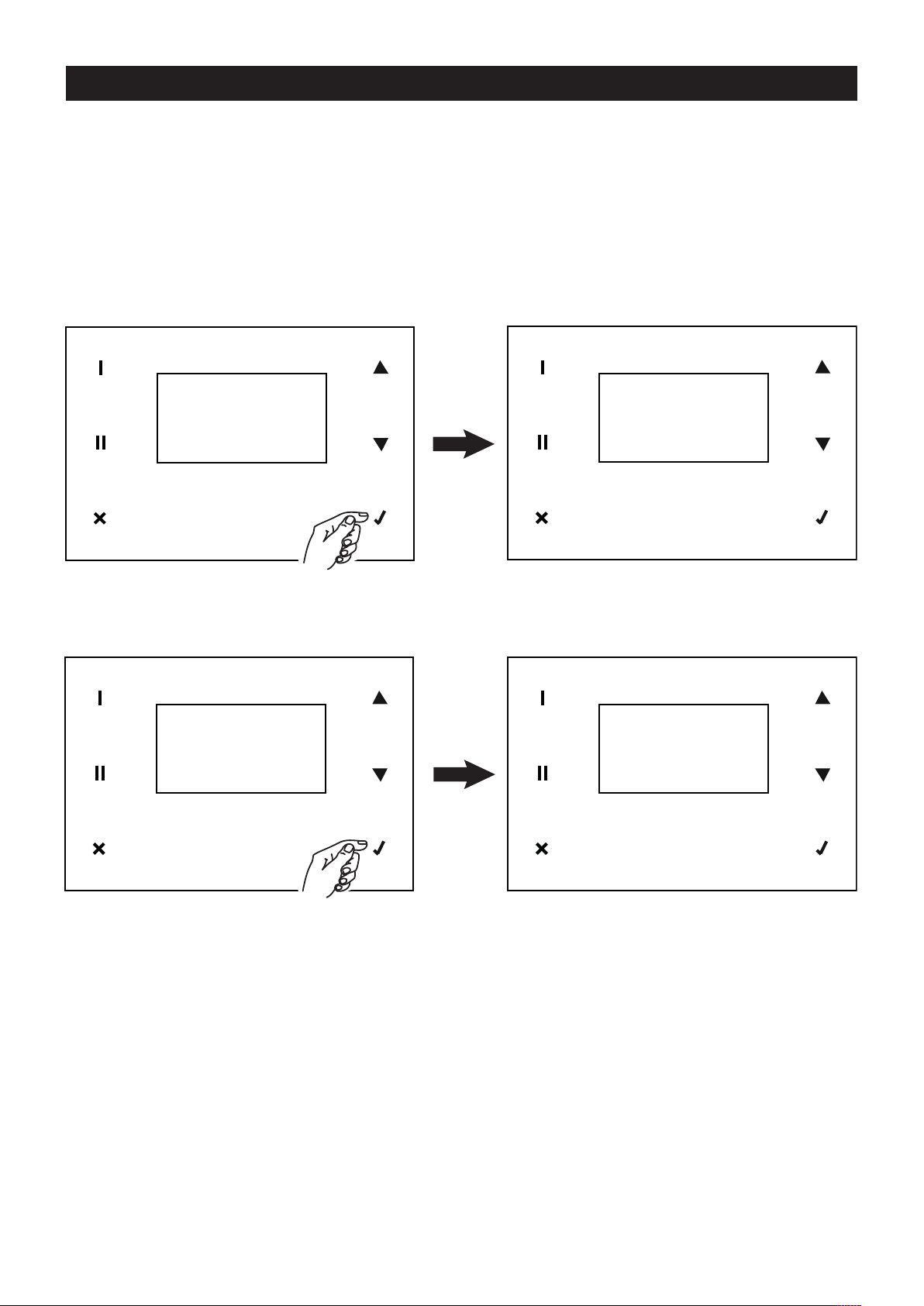
Impostazioni dell’installatore
Il menu dell’installatore presenta le seguenti opzioni:
INSTALL
SETUP BYP
RESET FIL
MBUS ID
PASSWORD
000
SPEED
LANGUAGE
NO FROST
13
Page 14
ITALIANO
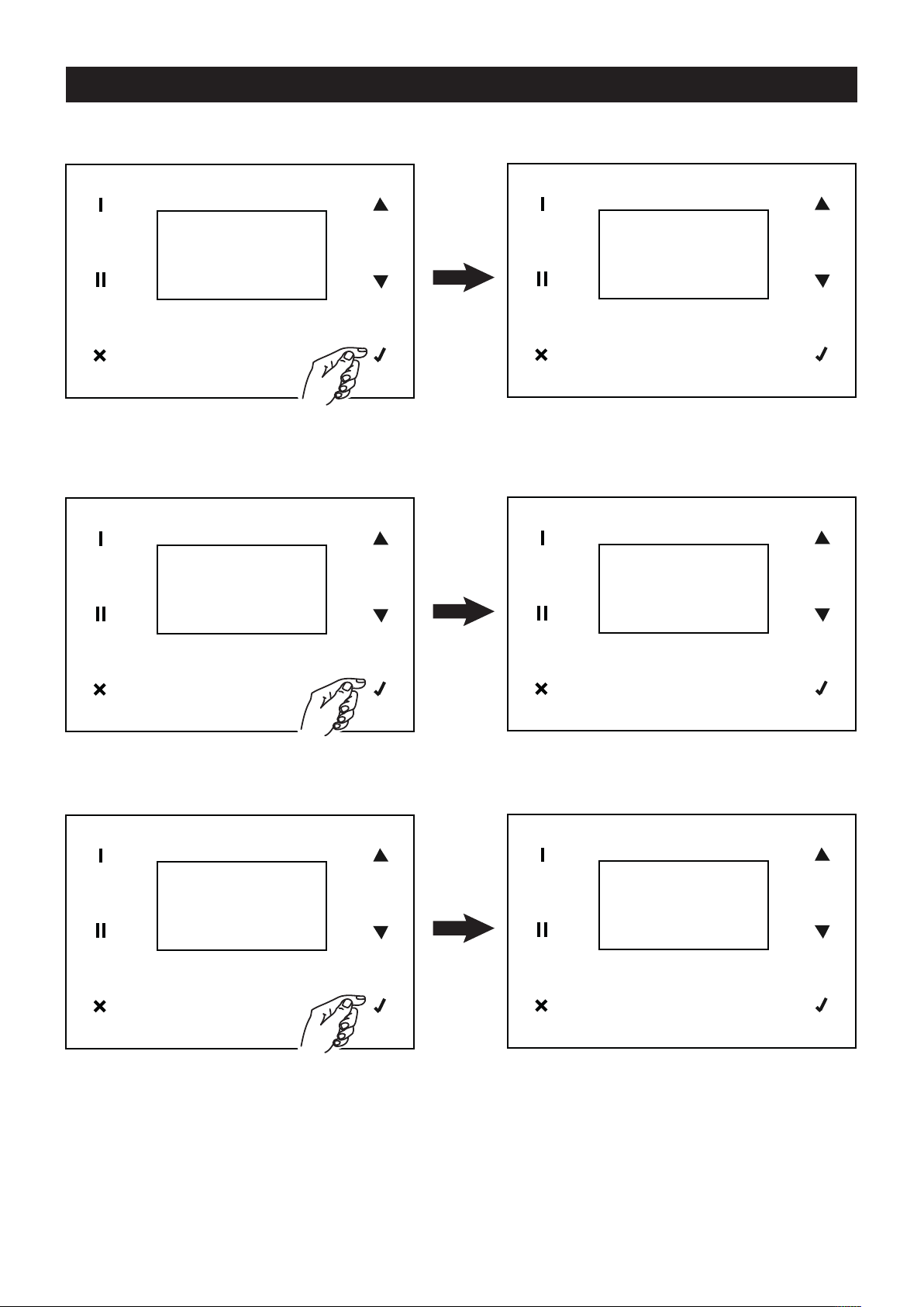
SET UP BYPASS
E’ la temperatura di setpoint per il bypass. Il valore di default, modificabile, è 18°C.
ETP BYP
INSTALL
SETUP BYP
RESET FIL
BUS ID
M
RESET FIL
E’ la variabile per il reset del contatore filtri sporchi. Il valore di default è NO. Può essere impostato a SI nel caso di
sostituzione dei filtri (o comunque quando si desidera)
S
018
NSTALL
I
SETUP BYP
RESET FIL
MBUS ID
MBUS ID
E’ l’indirizzo MODBUS del pannello comandi
INSTALL
SETUP BYP
RESET FIL
MBUS ID
RESET FIL
YES
MBUS ID
160
14
Page 15
ITALIANO
SPEED
E’ la variabile che definisce la velocità impostata per i motori di Supply (IN) e di exhaust (OUT), con i due valori
NORMAL e BOOST. I valori di default, modificabili in percentuale, sono:
VNORMAL_I 73%
NORNAL_O 73%
V
VBOOST_I 100%
VBOOST_O 100%
INSTALL
SPEED
LANGUAGE
O FROST
N
VNORMAL I
VNORMAL O
VBOOST I
VBOOST O
SPEED
LANGUAGE
E’ la variabile che definisce la lingua dei testi del pannello. Il valore di default, modificabile, è: ENG.
INSTALL
SPEED
LANGUAGE
NO FROST
LANGUAGE
ENG
NO FROST
E’ la variabile che definisce le possibili strategie per la funzione NO FROST. I valori possibili sono:
UN-BALAN.: sbilanciamento dei flussi;
HEATER: preheater;
HEAT FORC.: nel caso di strategia preheater attivata, permette all’installatore di controllare il funzionamento del
preheater, accendendolo per 15 s.
INSTALL
SPEED
LANGUAGE
NO FROST
UN-BALAN.
HEATER
HEAT FORC.
NOFROST
Page 16
ITALIANO
Alarm
Con questa opzione è possibile gestire tutte le possibili voci di allarme. In caso di più errori questi dovranno essere
gestiti uno per uno, a partire dal primo verificatosi. In queste situazioni viene emessa una segnalazione intermittente
“Alarm!” sulla schermata iniziale. Solo nel caso di allarme “No Frost” vengono visualizzati i messaggi intermittenti
Alarm!”, “Block!” , “OFF”.
“
E’ possibile in tutti i casi accedere al menu ALARM per visualizzare le azioni necessarie e procedere al reset degli
errori. Nel seguito vengono descritte le varie situazioni che generano segnalazioni di allarme.
Filtri
uando è trascorso il periodo di tempo preimpostato viene visualizzato un preallarme e viene richiesta un’attività
Q
di controllo/pulizia dei filtri.
LARM
MAIN MENU
USE MENU
ALARM
SETUP
HECK OR
C
CLEAR
FILTER
A
Quando è trascorso il periodo di tempo preimpostato viene visualizzato un allarme e viene richiesta un’attività di
sostituzione filtri. Dopo avere sostituito i filtri (vedi “Manutenzione e Pulizia’) è possibile resettare l’errore e il
contatore.
MAIN MENU
USE MENU
ALARM
SETUP
REPLACE
FILTER.
RESET? YES
ALARM
N.B. il contatore può anche essere resettato in qualunque momento, accedendo all’apposita funzione del Menu
Installatore.
16
Page 17

ITALIANO
Sonda T ext
Un guasto del sensore della temperatura esterna genera questa segnalazione. Dopo aver risolto il problema (tramite
intervento dell’Assistenza Tecnica) è possibile resettare l’errore (risposta “YES” su “CALL SERVICE”).
AIN MENU
M
USE MENU
ALARM
SETUP
EXT PROBE
CALL
SERVICE YES
ALARM
N.B. Il sistema non effettua automaticamente la chiamata al servizio Assistenza Tecnica.
Sonda T int
Un guasto del sensore della temperatura interna genera questa segnalazione. Dopo aver risolto il problema (tramite
intervento dell’Assistenza Tecnica) è possibile resettare l’errore (risposta “YES” su “CALL SERVICE”).
MAIN MENU
USE MENU
ALARM
SETUP
INT PROBE
CALL
SERVICE YES
ALARM
N.B. Il sistema non effettua automaticamente la chiamata al servizio Assistenza Tecnica.
Sonda T exh
Un guasto del sensore della temperatura dell’aria espulsa genera questa segnalazione. Dopo aver risolto il
problema (tramite intervento dell’Assistenza Tecnica) è possibile resettare l’errore (risposta “YES” su “CALL
SERVICE”).
MAIN MENU
USE MENU
ALARM
SETUP
EXH PROBE
CALL
SERVICE YES
ALARM
N.B. Il sistema non effettua automaticamente la chiamata al servizio Assistenza Tecnica.
17
Page 18

ITALIANO
No Frost
La procedura di anti congelamento viene eseguita automaticamente dall’apparecchio quando necessaria. In caso
di procedura non riuscita (Preheater con temperature troppo basse) viene generata una segnalazione bloccante. Il
sistema rimane inattivo per un’ora, dopo di che l’apparecchio resetta automaticamente l’errore, si riattiva e ripete
l ciclo dall’inizio.
i
MAIN MENU
USE MENU
ALARM
SETUP
Setup
Con questa opzione è possibile accedere all’impostazione di Data e Ora
MAIN MENU
USE MENU
ALARM
SETUP
ALARM
NO FROST
WAIT
1 HOUR
SETUP
DATE&HOUR
Procedere all’impostazione di Data e Ora nel modo seguente:
1. ricercare la variabile interessata alla modifica, premendo o ;
2. selezionare la variabile, premendo ;
3. ricercare il valore desiderato, premendo o ;
4. memorizzare il valore scelto, premendo ;
5. tornare al punto 1. e così via.
SETUP
DATE&HOUR
18
DATE&HOUR
FRIDAY
dd: 14
yy: 18
hh: 08
mm: 23
Page 19

ITALIANO
Info
Con questa opzione è possibile visualizzare le seguenti informazioni informazioni di sistema:
hmi;
firmware scheda;
le di configurazione.
fi
NFO
I
ALARM
SETUP
INFO
AIN MENU
M
S:0.9 6.0
M:0.9 6.0
CFG:6.0
Page 20

ITALIANO
2525
26 26
27 27
28 28
29 29
Manutenzione/Pulizia
Filtri
Tempi consigliati per la manutenzione: in generale, il
livello di inquinamento dell’aria è variabile in funzione
dell’area geografica di installazione; quindi, è variabile la
urata dei filtri; se ne consiglia in ogni caso la
d
sostituzione una volta all’anno. Tenendo presenti
queste considerazioni, gli allarmi per la manutenzione
dei filtri sono i seguenti (vedi anche paragrafo “Utilizzo”):
• pre-allarme: attiva l’ avviso di controllo e pulizia filtri
• allarme: attiva l’ avviso di filtri saturi
Con il reset dell’errore filtri viene resettato anche il
contatore.
NOTA La mancata pulizia o sostituzione dei filtri
comporta gravi inconvenienti per l’efficienza
dell’impianto, con:
- aumento delle perdite di carico nel circuito aria e
riduzione di portata aria;
- conseguente diminuzione della resa della macchina e
peggioramento del confort in ambiente.
Per accedere ai filtri eseguire le istruzioni seguenti:
• disconnettere l’apparecchio dalla rete elettrica.
• estrarre i filtri dall’apparecchio (fig. 25,26,27)
• pulire i filtri utilizzando un’aspirapolvere; è preferibile
sostituire i filtri dopo alcune puliture, e comunque
almeno 1 volta all’anno.
• rimontare i filtri (fig. 28,29,30)
20
Page 21

3030
3131
32 32
33 33
ITALIANO
34 34
In caso di prolungato arresto dell’apparecchio si
consiglia di rimuovere i filtri per prevenire i rischi di un
loro danneggiamento indotto dalla possibile formazione
di condensa.
Scambiatore di calore
Di norma lo scambiatore di calore non necessita di
frequenti interventi di pulizia. La loro esigenza può
essere determinata da un elevato livello di inquinamento
dell’aria (in ingresso ed uscita dall’abitazione) e dallo
scadente stato dei filtri.
Lo scambiatore di calore dovrebbe comunque essere
sostituito ogni 6 anni, anche in presenza di regolare
manutenzione dei filtri.
Per accedere allo scambiatore rispettare le istruzioni
seguenti:
• disconnettere l’apparecchio dalla rete elettrica;
• estrarre lo scambiatore (fig. 31,32,33);
• pulire lo scambiatore;
• rimontare lo scambiatore (fig. 34,35,36)
21
Page 22

ITALIANO
3636
3737
3838
• non impiegare prodotti abrasivi e/o corrosivi. (fig. 38)
• non utilizzare un panno ruvido e/o troppo imbevuto
d’acqua; l’acqua che penetrasse all’interno del
prodotto potrebbe determinare gravi danni.
Pulizia esterna
Per pulire le parti esterne dell’apparecchio rispettare le
istruzioni seguenti:
• disconnettere l’apparecchio dalla rete elettrica;
• utilizzare solamente un panno morbido leggermente
umido. (fig. 37)
22
Page 23

ITALIANO
Informazioni importanti per lo
smaltimento ambientalmente
compatibile
N ALCUNI PAESI DELL’UNIONE EUROPEA QUESTO
I
PRODOTTO NON RICADE NEL CAMPO DI
APPLICAZIONE DELLA LEGGE NAZIONALE DI
RECEPIMENTO DELLA DIRETTIVA RAEE E QUINDI
NON È IN ESSI VIGENTE ALCUN OBBLIGO DI
RACCOLTA DIFFERENZIATA A FINE VITA.
Questo prodotto è conforme alla Direttiva
EU2002/96/EC.
Il simbolo del bidone barrato riportato
sull’apparecchio indica che il prodotto, alla
fine della propria vita utile, dovendo essere
trattato separatamente dai rifiuti domestici,
deve essere conferito in un centro di
raccolta differenziata per apparecchiature
elettriche ed elettroniche oppure
riconsegnato al rivenditore al momento dell’acquisto di
una nuova apparecchiatura equivalente.
L’utente è responsabile del conferimento
dell’apparecchio a fine vita alle appropriate strutture di
raccolta, pena le sanzioni previste dalla vigente
legislazione sui rifiuti.
L’adeguata raccolta differenziata per l’avvio successivo
dell’apparecchio dismesso al riciclaggio, al trattamento
e allo smaltimento ambientalmente compatibile
contribuisce ad evitare possibili effetti negativi
sull’ambiente e sulla salute e favorisce il riciclo dei
materiali di cui è composto il prodotto.
Per informazioni più dettagliate inerenti i sistemi di
raccolta disponibili, rivolgersi al servizio locale di
smaltimento rifiuti o al negozio in cui è stato effettuato
l’acquisto.
I produttori e gli importatori ottemperano alla loro
responsabilità per il riciclaggio, il trattamento e lo
smaltimento ambientalmente compatibile sia
direttamente sia partecipando ad un sistema collettivo.
23
Page 24

ENGLISH
Compliance with Building Codes
he most recent laws introduced to reduce energy
T
consumption require compliance with a series of
constraints which concern the performance provided
and the energy consumption of ventilation equipment.
In particular, the 2006 Edition of the U.K “Building
egulations Document F1”: Means of Ventilation (ADF
R
applicable in England and Wales) details 4 clearly
defined systems of ventilation to dwellings. System 4 Continuous mechanical extract with heat recovery
(MVHR) is complied with by the new VORT HR 200 ultrahigh efficiency whole house heat recovery ventilation
system.
In addition the unit fully complies with the requirements
of the “Code for Sustainable Homes” which details 6
levels of C02emission improvement over 2006 Building
Requirements. In order to operate in accordance with
ADF, the unit must be set by the installer to deliver air
volumes a stated in the Approved Document and as per
the extract of ADF on page 38 of this brochure.
Description and operation
VORT HR 200 (henceforth “the appliance”) is an
extremely high efficiency centralised heat recovery
ventilation system that can be floor mounted using the
special optional kit or wall mounted using the special
hooks provided.
Normally, stale air is extracted from “service” rooms
such as kitchens, bathrooms and laundries; at the same
time, fresh air from outdoors is ducted into rooms that
are normally lived in such as bedrooms, studies and
sitting rooms. The air flows required are detailed in
current national regulations; in the UK, the UK “Building
Regulations Document F1” apply.
During normal operation the total volumes of air
extracted and air fed back in are essentially the same.
The incoming and outgoing air flow are perfectly
separate and suitably filtered. During the cold season,
heat from expelled air is transferred to incoming air. The
condensation created in the process, which is collected
inside the product, must then be piped to the outside.
The appliance silently and continuously ventilates the
house removing stale air and replacing it with filtered
fresh air from the outside. Inside the heat exchanger,
which is the key element in the appliance, heat is
exchanged between the two flows of air and this
guarantees the energy savings that the VORT HR 200
offers.
Guarantee and responsibility
uarantee
G
The appliance is guaranteed for 2 years from the date of
purchase.
The guarantee does not apply to:
• installation/removal costs;
damage caused by improper or negligent use of the
•
appliance;
• damage caused by repairs or attempted repairs or by
third parties not authorised by Vortice.
Responsibility
The appliance is designed for “balanced ventilation
systems”. Any other use that has not been previously
discussed with a Vortice expert shall be considered
improper. In this case, Vortice shall not be held
responsible for any malfunction or failure.
Vortice shall not be held responsible for breakdowns
due to:
• improper use of the appliance;
• normal wear and tear of the appliance;
• the user’s failure to comply with the instructions
provided in this manual.
24
Page 25

ENGLISH
1 1
A
Safety
Warning:
!
This symbol indicates precautions that must
• Follow the safety instructions to prevent any harm to
he user.
t
• Do not use this appliance for functions other than
those described in this booklet.
• After removing the appliance from its packaging,
ensure that it is complete and undamaged: if in any
doubt, contact a professionally qualified electrician or
a Vortice Service Centre.
• Do not leave packaging within the reach of children or
less able persons.
• Certain fundamental rules must be observed when
using any electrical appliance:
- never touch appliances with wet or damp hands;
- never touch appliances while barefoot.
• This appliance is not suitable for use by individuals
(including children) with reduced physical, sensorial or
mental capacities, or by inexperienced or untrained
individuals, unless they are supervised or instructed in
its use by a person responsible for their safety.
Children must always be supervised to ensure that
they do not play with the appliance.
• Do not us the appliance near inflammable substances
and vapours (alcohol, insecticides, petrol, etc.).
• Store the appliance out of the reach of children and
less able persons if you decide to disconnect it from
the power supply and use it no more.
Caution:
This symbol indicates precautions that must
!
be taken to avoid damaging the appliance
•Do not make modifications of any kind to this
appliance.
• The maintenance instructions must be followed to
prevent any damage to and/or excessive wear and tear
of the appliance.
• Do not expose the appliance to the elements (rain, sun,
etc.).
•Do not leave objects standing on the appliance.
• The interior of the appliance must only be cleaned by
qualified personnel.
• Regularly inspect the appliance for visible defects. If
the appliance does not function correctly, do not use it
and contact a Vortice Service Centre immediately
• If the appliance does not function correctly or develops
a fault, contact a Vortice Service Centre immediately
and ensure that only genuine original Vortice spares
are used for any repairs.
• Should the appliance be dropped or suffer a heavy
blow, have it checked immediately by a Vortice Service
Centre.
• The appliance must be installed by a professionally
ualified electrician.
q
• The appliance must be mounted in such a way as to
ensure that under normal operating conditions, no one
can come into contact with any of the moving parts or
live electrical components.
For maintenance work (e.g. removing the heat
•
exchanger), the appliance should first be turned OFF
then disconnected from the mains.
• The electrical system to which the appliance is
connected must conform to applicable standards.
• A multi-pole switch must be used to install the
appliance. The gap between the switch contacts must
be no less than 3 mm.
• The electrical power supply/socket to which the
appliance is to be connected must be able to provide
the maximum electrical power required by the
appliance. If it cannot do so, arrange for a qualified
electrician to make the necessary modifications.
• Switch OFF the system’s main switch:
- if the appliance does not function correctly;
- before cleaning the outside of the appliance;
- if you decide not to use the appliance for any length
of time.
• The appliance cannot be used in combination with
water heaters, room heaters, etc., nor must it be used
to drain hot water away from such appliances.
• The appliance must expel air directly to the outside
through a dedicated outlet.
• The flow of extracted air must be clean (that is free of
grease, soot, chemical and corrosive agents and
explosive or flammable mixtures).
• Keep the appliance intake and outlet grilles free to
ensure optimum air flow.
• Specifications for the power supply must correspond
to the electrical data on ID plate A (fig. 1).
25
Page 26

ENGLISH
2 2
33
Items supplied
he main appliance components are as follows:
T
• an outer casing and front cover in painted sheet metal;
the casing houses the intake/outlet hose connections
and the electrical connection box; the casing also
houses the internal components and heat exchanger
n an air tight housing;
i
• internal ducts in EPP (expanded polypropylene) that
distribute flow of air while maximising heat insulation
and minimising losses.
• the plastic resin, counterflow, heat exchanger whose
particular shape guarantees the highest possible
efficiency in terms of heat exchange (up to 93%);
• 2 filters with G3 level particle retention;
• 2 brushless motors connected to centrifugal fans;
• the electronic circuit board that processes power
supply, appliance commands and controls;
• 3 temperature sensors:
-internal air;
-external air;
-exhaust air;
• filter replacement warning timer;
• output for connection to a pre-heater (No frost
operation)
• optional connection to a switch for maximum speed
(boost).
Accessories supplied
The accessories supplied as standard include:
• 1 x condensation drainage hose coupling
•1x condensation drainage hose;
• 2 x rawlplugs with hooks for wall-mounting the
appliance
• Wired remote control with LCD display, through which
initial set-up can be performed during installation
(carried out by the installer) as well as device operation
managemant.
Under normal operating conditions, condensation
gathers at the bottom of the appliance. In order to
dispose of it, the small hose (fig.2) provided must be
attached to the coupling on the underside of the
ppliance and connected to a drainage hose (see
a
Assembly).
The appliance must be easily accessible for
servicing/maintenance purposes. It is important to leave
a space of at least 50 cm in front of the front panel to
facilitate the cleaning and replacement of the heat
exchanger and filters (fig. 3).
Installation
The appliance must be installed according to the safety
regulations currently in force in the country of
destination, and the instructions provided by this
booklet.
Prerequisites
The appliance must be fitted to an internal surface or
wall of the home that is structurally sound enough to
bear its weight.
The ducts used for carrying ducting must be of the
correct size.
Ducts to and from the exterior must be thermally
insulated and not subject to vibration.
The 125 mm standard diameter inlet and outlet pipes
must be fixed to the corresponding spigots on the
appliance by means of clips or some other suitable
fastening system.
26
Checks on delivery
On delivery, check the appliance for any faults before
proceeding with the installation. More specifically:
• firstly remove it from the packaging ensuring that the
name and description shown on the box correspond;
• when the appliance has been removed from the
packaging, check that there is no visible damage then
make sure that the small condensation drainage hose
is present along with the instruction manual.
Page 27

ENGLISH
7 7
8 8
Assembly
The appliance comes with 2 rawlplugs with hooks for
wall-mounting.
Establish exactly where the appliance is to be
ositioned, bearing in mind the installation
p
requirements.
Vertical mounting
Fix the hooks to the wall as shown in the diagrams that
follow (figs. 4,5,6,7,8).
4
6
5
27
Page 28

ENGLISH
E
XTRACT
T
O
EXTERNAL
S
UPPLY
F
ROM
EXTERNAL
E
XTRACT
F
ROM
INTERNAL
S
UPPLY
T
O
INTERNAL
10 10
11 11
12 12
Floor mounting (optional kit)
The appliance can be horizontally floor mounted using
the special optional kit.
ipework connections
P
(fig. 9).
9
The spigots on the appliance measure 125 mm in
diameter. Ducts may be connected to the appliance inlet
and outlets. Each connection is illustrated below with a
diagram that shows the direction of the air flow (in and
out).
Fresh air inlet
(fig. 11)
This inlet is used for carrying fresh air from the exterior;
the duct must be thermally insulated and have devices
fitted to absorb vibration. If air intake system is on the
roof, it must be designed so as to prevent the formation
of condensation and the entry of rain water.
Stale air extraction inlet
Stale air outlet
(fig. 10).
This outlet is used to expel stale air once it has been
treated by the heat exchanger. The ducting for this stale
air must be thermally insulated (to prevent the formation
have condensation on internal and external
components) and devices fitted to absorb vibration. If
the drainage system is on the roof, it must be designed
so as to prevent the formation of condensation and the
entry of rain water.
(fig. 12)
This inlet carries extracted stale air from the house. The
duct needs to be thermally insulated.
28
Page 29

19 19
ENGLISH
13 13
14 14
15 15
17 17
18 18
Air outlet
(fig. 13)
This outlet delivers fresh air into the house once it has
been treated in the heat exchanger.
Connecting the condensation drainage hose.
The connection point for this hose is located on the
underside of the appliance; it is to be connected
following the description below (figs.14,15,16,
17,18,19,20).
29
Page 30

ENGLISH
2020
2121
83
83
1276833/,('
22 22
83
,1$662&,$7,21:,7+7+,6%2;
7+()5$0(,612772%(,167$//('
1276833/,('
83
Condensation is drained away by connecting the hose
provided to the condensation drainage coupling.
To prevent formation of air locks a U-bend must be
created with the hose as shown in fig. 21.
Mounting the wired remote control
30
Page 31

2323
N
L
230V ~ 50Hz
1
PE
GNYE
B
U
BN
B
N
B
U
2
230V ~50Hz
MAINS
M
AINS
PREH
L
N
N
P
REH
1
Mains 2 poles switch
2
Preheater (remote 230Vac relay coil )
2424
3
4
V
CC
A
B
G
ND
VCC
A
B
G
ND
GND
BOOST
HMI
B
OOST
3
Dry contact (remote switch / relay )
4
Remote H MI
ENGLISH
Electrical connections
31
Page 32

ENGLISH
Function
otors
M
The appliance is equipped with:
• two brushless motors specifically designed to
guarantee very low energy consumption thanks to
their high efficiency. These motors drive two
entrifugal fans which extract the stale damp air from
c
service rooms (kitchens, bathrooms, washrooms, etc)
and introduce fresh external air into living areas (sitting
rooms, dining rooms, bedrooms, etc.);
Heat exchanger
The two air flows, intake and extract, meet in the
appliance, (without ever actually coming into direct
contact so as not to jeopardise the quality of incoming
air) inside the heat exchanger where the warm
outgoing/extracted air passes its heat to the cold
incoming air, thus minimising the temperature variation
in the areas served.
Filters
Two G3 filters housed in the inlet and extraction ducts
close to the heat exchanger and accessible by removing
the front panel, protect the appliance from impurities in
the extracted stale air and prevent the introduction of
polluted air into the areas served by the system.
The condition of the filters can be checked by removing
the front panel and extracting them from their holders.
Replacing a standard G3 filter in the air intake system
with an optional G5 filter enhances the degree of
filtering.
Use
NFORMATIONS
I
The device operates continuously. All functions can be
controlled via the wired control panel equipped with
touch screen:
B
A
A: touch area
B: display
MEANING OF ICONS/BUTTONS IN THE TOUCH/AREA
1
4
Anti-frost protection
When weather conditions deteriorate and the formation
of frost on the heat exchanger walls become more likely,
the electronic circuit board automatically adjusts fan
speeds and air flow parameters.
While the automatic de-frosting cycle is in operation, the
user cannot change the appliance operating speed.
2
3
1: date/time display (last line of the display);
2: T
, T
, T
int
3: exit without saving and return to the previous page;
4: speed increase (from Normal to Boost) either moving
5: speed decrease (from Boost to Normal) either moving
6: confirmation of the current choice and go to the next
ext
the cursor to the line above or increasing the value;
the cursor to the line below or decreasing the value;
page with saving of current data.
display (last two lines of the display);
exh
5
6
32
Page 33

ENGLISH
CONTROL PANEL FUNCTIONS
Upon first activation, carried out by the installer, the
display will show the Vortice logo and, after 10 seconds,
the pre-set operating speed: NORMAL
NOTE: in general, in the absence of user input, after two
minutes the display will return to the logo screen without
saving any changes. In this case press to reactivate
thr main menu.
In this phase, you can immediately increase the speed to the maximum value BOOST via the button
( to decrease from BOOST to NORMAL).
NORMAL
13 / 01 / 18 08:07
NORMAL
13 / 01 / 18 08:07
BOOST
13 / 01 / 18 08:07
You can change the type of data shown on the bottom of the display by using the buttons: and
NORMAL
13 / 01 / 18 08:07
: date and time : temperatures: External, Internal, Exhaust
NORMAL
Ext+19° Int+21°
Exh+21°
33
Page 34

ENGLISH
All other functions can be reached from the main menu.The main menu can be displayed by pressing on the home
screen.
AIN MENU
M
NORMAL
13 / 01 / 18 08:07
Main menu
Use menu
With this option and by entering the password on the next screen, you can access installer and factory settings.
Installer settings: password: 023
Factory settings: password not available
USE MENU
ALARM
SETUP
INFO
MAIN MENU
USE MENU
ALARM
SETUP
Installer settings:
The installer menu offers the following options:
INSTALL
SETUP BYP
RESET FIL
MBUS ID
PASSWORD
000
34
SPEED
LANGUAGE
NO FROST
Page 35

ENGLISH
SET UP BYPASS
This is the setpoint temperature for bypass. The editable default value is 18°C.
NSTALL
I
SETUP BYP
RESET FIL
MBUS ID
SETP BYP
018
RESET FIL
This is the variable for dirty filter counter reset. The default value is NO. It can be set to YES in the case of filter
replacement (or however when desired)
ESET FIL
INSTALL
SETUP BYP
RESET FIL
MBUS ID
R
YES
MBUS ID
This is the control panel MODBUS address
INSTALL
SETUP BYP
RESET FIL
MBUS ID
MBUS ID
160
35
Page 36

ENGLISH
SPEED
This is the variable that defines the speed set for Supply (IN) and exhaust (OUT) motors, with two values NORMAL
and BOOST. The default values, which are editable as a percentage, are:
VNORMAL_I 73%
NORNAL_O 73%
V
VBOOST_I 100%
VBOOST_O 100%
NSTALL
I
SPEED
LANGUAGE
NO FROST
VNORMAL I
VNORMAL O
VBOOST I
VBOOST O
LANGUAGE
This is the variable that defines the panel text language. The editable default value is: ENG.
PEED
S
INSTALL
SPEED
LANGUAGE
NO FROST
LANGUAGE
ENG
NO FROST
This is the variable that defines the possible strategies for NO FROST operation. The possible values are:
UN-BALAN.: flow unbalance
HEATER: pre-heater
HEAT FORC.: in the case that the pre-heater strategy is activated, this permits the installer to control pre-heater
operation, switching it on for 15 s.
INSTALL
SPEED
LANGUAGE
NO FROST
UN-BALAN.
HEATER
HEAT FORC.
NOFROST
36
Page 37

ENGLISH
Alarm
This option allows you to manage all possible alarm messages. Multiple errors must be managed one by one,
starting from the first one that occurred. In these situations, an intermittent "Alarm!" signal will be emitted on the
home screen. The intermittent messages "Alarm!", "Block!" and “OFF” will be displayed only in the event of a "No
rost" alarm.
F
In all cases, you can switch on the ALARM menu to view the necessary actions and reset errors. The various
situations that generate alarm signals are described below.
Filters
hen the preset time period has elapsed, a pre-alarm is displayed and a filter check/cleaning is required.
W
MAIN MENU
USE MENU
ALARM
SETUP
CHECK OR
CLEAR
FILTER
ALARM
When the preset time period has elapsed, an alarm is displayed and filter replacement is required. The error and
counter can be reset after filter replacement (see "Maintenance and Cleaning").
MAIN MENU
USE MENU
ALARM
SETUP
REPLACE
FILTER.
RESET? YES
ALARM
NOTE: the counter can also be reset at any time by accessing the corresponding function in the Installer Menu.
37
Page 38

ENGLISH
T ext probe
A fault on the external temperature sensor generates this signal. After having resolved the problem (through
Technical Service intervention), you can reset the error (answer "YES" for "CALL SERVICE").
LARM
MAIN MENU
USE MENU
ALARM
SETUP
EXT PROBE
CALL
SERVICE YES
Note: The system does not automatically call Technical Service.
T int probe
A fault on the internal temperature sensor generates this signal. After having resolved the problem (through
Technical Service intervention), you can reset the error (answer "YES" for "CALL SERVICE").
A
MAIN MENU
USE MENU
ALARM
SETUP
INT PROBE
CALL
SERVICE YES
ALARM
Note: The system does not automatically call Technical Service.
T exh probe
A fault on the exhaust air temperature sensor generates this signal. After having resolved the problem (through
Technical Service intervention), you can reset the error (answer "YES" for "CALL SERVICE”.
MAIN MENU
USE MENU
ALARM
SETUP
EXH PROBE
CALL
SERVICE YES
ALARM
NOTE: The system does not automatically call Technical Service.
38
Page 39

ENGLISH
No Frost
The frost protection procedure is carried out automatically by the device when necessary. A blocking signal will be
generated if the procedure does not work (pre-heater with temperature too low). The system will remain inactive for
an hour; after which, the device will automatically reset the error, and the cycle will reactivate and repeat from the
beginning.
AIN MENU
M
USE MENU
LARM
A
SETUP
Setup
You can access the Date and Time setting with this option
MAIN MENU
USE MENU
ALARM
SETUP
ALARM
NO FROST
WAIT
1 HOUR
SETUP
DATE&HOUR
Set the Date and Time as follows:
1. search for the variable you wish to change, pressing or ;
2. select the variable, pressing ;
3. search for the desired value, pressing or ;
4. store the selected value, pressing ;
5. return to point 1 and so on.
SETUP
DATE&HOUR
DATE&HOUR
FRIDAY
dd: 14
yy: 18
hh: 08
mm: 23
39
Page 40

ENGLISH
Info
You can view the following system information with this option:
hmi;
board firmware;
onfiguration file.
c
ALARM
SETUP
NFO
I
AIN MENU
M
INFO
S:0.9 6.0
M:0.9 6.0
CFG:6.0
40
Page 41

ENGLISH
2525
26 26
27 27
28 28
29 29
Maintenance/Cleaning
ilters
F
Recommended maintenance intervals: because levels
of air pollution depend typically on geographical
location and are variable, the life of the filters will be
similarly variable. With this general consideration in
ind, check following alarms for filter maintenance (see
m
also “Use”):
Pre-alarm: actives the notice about filters checking and
-
cleaning
- Alarm: actives the notice about clogged filters
Resetting filters timer (See: Operation and Use: “User
operation menu”, “Resetting filters timer”) is resetted
also the counter.
NOTE Failure to clean or replace filters can seriously
affect system efficiency, causing:
- increased pressure losses in the air circulation system
and reduced airflow;
- drop in system performance and comfort levels
caused by pressure losses.
To access the filters, follow the instructions below:
• disconnect the appliance from the mains.
• remove the filters from the appliance (figs. 25,26,27)
• clean the filters using a vacuum cleaner; you are
advised to replace the filters after cleaning them a few
times but least once a year.
• refit the filters (figs. 28,29,30)
41
Page 42

ENGLISH
3030
3131
33 33
34 34
If the appliance remains out of use for extended periods,
we advise removing the filters to prevent any possible
damage from the build-up of condensation.
Heat exchanger
Heat exchangers do not usually need frequent cleaning.
Any need for cleaning can be determined by a high
degree of air pollution (both entering and leaving the
house) and by the filters being in poor condition.
The heat exchanger should however be replaced every
six years even if the filters have been regularly serviced.
To access the heat exchanger, follow the instructions
below:
• disconnect the appliance from the mains;
• remove the heat exchanger (figs. 31,32,33);
• clean the heat exchanger;
• refit the heat exchanger (figs. 34,35,36)
42
Page 43

ENGLISH
35 35
3636
3737
3838
• do not use abrasive and/or corrosive products (fig. 38);
• do not use a rough and/or soaking cloth; any water
that gets inside the appliance could cause serious
damage.
Cleaning the outside
To clean the outside of the appliance, follow the
instructions below:
• disconnect the appliance from the mains;
• only use a soft slightly damp cloth (fig. 37);
43
Page 44

Table 1.1 A
Room Minimum intermittent extract rate Continuous rate
Minimum high rate Minimum low rate
Kitchen 30 l/s (adjacent to hob); Total extract rate
or 60 l/s elsewhere 13 l/smust be at least
Utility room 30 l/s 8 l/s
the whole building
Bathroom 15 l/s 8 l/s
ventilation rate in
Sanitary Accomodation 6 l/s
Ta ble 1.1B
Table 1.1 B
Number of bedrooms in dwelling
12345
Whole building ventilation rate (l/s) 1317212529
Minimum value in any dwelling of 0,3 l/s per m
2
oor area
BUILDING REGULATIONS DOCUMENT F1 2006
CONTINUOUS MECHANICAL SUPPLY & EXTRACT
VENTILATION WITH HEAT RECOVERY
A continuous balanced mechanical central supply and extract system to
be positioned in loft or cupboard space. An integral heat exchanger
recovers a large percentage of heat energy that would have otherwise
been lost. In employing this type of system, there is no need to install
background ventilators in the dwelling.
CONTINUOUS SUPPLY AND EXTRACT
1 Determine the whole building ventilation rate from Table 1.1B
Allow for inltration by subtracting
- for multi storey dwellings: 0.04 x gross internal volume of dwelling
heated space (m3)
- for single storey dwellings: 0.06 x gross internal volume of dwelling
heated space (m
3
)
2 Calculate the whole dwelling extract rate at maximum operation by
adding the individual room rates for ‘minimum high rate’ from Table 1.1A
3 The required air flow rates as as follows:
Maximum Extract Rate (boost) is the greater step of 1 and 2 above.
The Minimum individual room extract rates sholuld be at least those
given in Table 1.1A for minimum high rate
Minimum air supply rate should be at least the whole building
ventilation rate in 1 above.
4 No Background ventilators are required with System 4
In addition, the minimum ventilation rate should not be less than 0.3 l/s per m2internal oor area (this includes each oor, e.g.
for a two-storey building, add the ground and rst oor areas).
This is based on two occupants in the main bedroom and a single occupant in all other bedrooms. This should be used as the
default value. If a greater level of occupance is expected, then add 4 l/s per occupant.
SYSTEM 4
Table 1.1 A
etar suounitnoC etar tcartxe tnettimretni muminiMmooR
Minimum high rate Minimum low rate
etar tcartxe latoT;)boh ot tnecajda( s/l 03nehctiK
tsael ta eb tsums/l 31 erehwesle s/l 06 ro
s/l 8 s/l 03 moor ytilitU
the whole building
s/l 8 s/l 51 moorhtaB
ventilation rate in
s/l 6 noitadomoccA yratinaS
Ta ble 1.1B
Table 1.1 B
Number of bedrooms in dwelling
12345
9252127131 )s/l( etar noitalitnev gnidliub elohW
Minimum value in any dwelling of 0,3 l/s per m
2
BUILDING REGULATIONS DOCUMENT F1 2006
CONTINUOUS MECHANICAL SUPPLY & EXTRACT
VE N T I L AT I O N W ITH HEAT RECOVERY
A continuous balanced mechanical central supply and extract system to
be positioned in loft or cupboard space. An integral heat exchanger
recovers a large percentage of heat energy that would have otherwise
been lost. In employing this type of system, there is no need to install
background ventilators in the dwelling.
CONTINUOUS SUPPLY AND EXTRACT
1 Determine the whole building ventilation rate from Table 1.1B
-for multi storey dwellings: 0.04 x gross internal volume of dwelling
heated space (m3)
-for single storey dwellings: 0.06 x gross internal volume of dwelling
heated space (m3)
2 Calculate the whole dwelling extract rate at maximum operation by
adding the individual room rates for ‘minimum high rate’ from Table 1.1A
3 The required air ow rates as as follows:
Maximum Extract Rate (boost) is the greater step of 1 and 2 above.
The Minimum individual room extract rates sholuld be at least those
given in Table 1.1A for minimum high rate
Minimum air supply rate should be at least the whole building
ventilation rate in 1 above.
4 No Background ventilators are required with System 4
In addition, the minimum ventilation rate should not be less than 0.3 l/s per m
2
This is based on two occupants in the main bedroom and a single occupant in all other bedrooms. This should be used as the
default value. If a greater level of occupance is expected, then add 4 l/s per occupant.
SYSTEM 4
BATHROOM
B
EDROOM
H
EAT RECOVERY
U
NIT
KITCHEN
LIVING
ROOM
ENGLISH
Page 45

ENGLISH
Important information on eco-compatible
disposal
N CERTAIN EUROPEAN UNION COUNTRIES, THIS
I
PRODUCT DOES NOT FALL WITHIN THE
REQUIREMENTS OF THE NATIONAL LAWS
IMPLEMENTING DIRECTIVE RAEE, AND, IN THESE
COUNTRIES THE PRODUCT IS NOT SUBJECT TO
EPARATE DISPOSAL OPERATIONS AT THE END OF
S
ITS WORKING LIFE.
This product complies with European Directive
2002/96/EC.
At the end of its useful life, the product
marked with the crossed out wheeled bin
must be disposed of separately from urban
waste. It must be taken to a differentiated
disposal centre for electrical and electronic
appliances or be returned to the retailer
when a new equivalent appliance is bought.
Subject to current legislation on waste disposal, the
user is legally responsible for taking the appliance at the
end of its useful life to a suitable disposal centre.
Appropriate differentiated waste collection for
subsequent recycling, treatment and environmentfriendly disposal of the discarded equipment helps to
prevent possible negative environmental and health
effects and encourages recycling of the component
materials of the equipment.
For further information about available waste disposal
systems, contact your local waste disposal service or
the shop where you bought the product.
The manufacturers and importers comply with their
responsibility for recycling, treating, and environmentally
compatible disposal of waste both directly and
collectively.
45
Page 46

Vortice Elettrosociali S.p.A. si riserva il diritto di apportare tutte le varianti migliorative ai prodotti in corso di vendita.
Vortice Elettrosociali S.p.A. reserves the right to make improvements to products at any time and without prior notice.
La société Vortice Elettrosociali S.p.A. se réserve le droit d'apporter toutes les variations afin d'améliorer ses produits en cours de commercialisation.
Die Firma Vortice Elettrosociali S.p.A. behält sich vor, alle eventuellen Verbesserungsänderungen an den Produkten des Verkaufsangebots vorzunehmen.
Vortice Elettrosociali S.p.A. se reserva el derecho de incorporar todas las mejoras necesarias a los productos en fase de venta.
Vortice Elettrosociali S.p.A.
VORTICE ELETTROSOCIALI S.p.A. VORTICE LIMITED
Strada Cerca, 2- frazione di Zoate Beeches House-Eastern Avenue
20067 TRIBIANO (MI) Burton on Trent
Tel. +39 02-90.69.91 DE 13 0BB
ITALIA Tel. +44 1283-49.29.49
vortice-italy.it UNITED KINGDOM
postvendita@vortice-italy.com vortice.ltd.uk
sales@vortice.ltd.uk
VORTICE LATAM S.A. VORTICE VENTILATION SYSTEM (CHANGZHOU) CO.LTD
3er Piso, O
cina 9-B, Edi cio Building 19, No.388 West Huanghe Road, Xinbei District,
Meridiano Changzhou, Jiangsu Province CAP:213000
Guachipelin, Escazú, San José CHINA
PO Box 10-1251 vortice-china.com
Tel +506 2201 6242; vortice@vortice-china.com
COSTA RICA
vortice-latam.com
info@vortice-latam.com
46
Page 47

474849
Page 48

Page 49

Page 50

A
TAGLIA N D O I NTERV E N T O I N GARAN Z I A
CERTIFICATE OF WORK PERFORMED UNDER GUARANTEE
COUPON INTERVENTION SOUS GARANTIE
DATA INTERVENTO
DATE OF WORK - DATE INTERVENTION
TIMBRO CENTRO ASSISTENZA
STAMP OF TECHNICAL ASSISTANCE CENTRE - CACHET SERVICE APRES-VENTE
TAGLIA N D O I NTERV E N T O I N G ARANZ I A
CERTIFICATE OF WORK PERFORMED UNDER GUARANTEE
COUPON INTERVENTION SOUS GARANTIE
DATA INTERVENTO
DATE OF WORK - DATE INTERVENTION
TIMBRO CENTRO ASSISTENZA
STAMP OF TECHNICAL ASSISTANCE CENTRE - CACHET SERVICE APRES-VENTE
TAGLIA N D O I NTERV E N T O I N G ARANZ I A
CERTIFICATE OF WORK PERFORMED UNDER GUARANTEE
COUPON INTERVENTION SOUS GARANTIE
DATA INTERVENTO
DATE OF WORK - DATE INTERVENTION
TIMBRO CENTRO ASSISTENZA
STAMP OF TECHNICAL ASSISTANCE CENTRE - CACHET SERVICE APRES-VENTE
TAGLIA N D O I NTERV E N T O I N G ARANZ I A
CERTIFICATE OF WORK PERFORMED UNDER GUARANTEE
COUPON INTERVENTION SOUS GARANTIE
DATA INTERVENTO
DATE OF WORK - DATE INTERVENTION
TIMBRO CENTRO ASSISTENZA
STAMP OF TECHNICAL ASSISTANCE CENTRE - CACHET SERVICE APRES-VENTE
B
C
D
50
Page 51

ITALIA
C
O
NDIZIONI DI GARANZIA
VORTICE ELETTROSOCIALI SPA garantisce i suoi prodotti per 2
anni dalla data dell’acquisto, che deve essere comprovata da
idoneo documento fiscale (scontrino o fattura), rilasciato dal venditore.
Nel suddetto periodo di garanzia VORTICE ELETTROSOCIALI SPA
si impegna, dopo aver effettuato le opportune valutazioni tecniche,
a riparare o a sostituire gratuitamente le parti dell’apparecchio che
risultassero affette da difetti di fabbricazione. La presente garanzia,
da attivare nei modi e nei termini di seguito indicati, lascia
impregiudicati i diritti derivanti al consumatore dalla applicazione del
D. lgs. 24/2002.Tali diritti, conformemente alla legge, potranno
essere fatti valere esclusivamente nei confronti del proprio
venditore.
La presente garanzia è valida su tutto il territorio italiano.
Modalità e condizioni di attivazione della garanzia
Gli interventi in garanzia (riparazioni o sostituzioni del prodotto
ovvero delle parti difettose) saranno eseguiti presso uno dei Centri di
Assistenza Tecnica autorizzati da VORTICE ELETTROSOCIALI SPA,
il cui indirizzo è disponibile sull’elenco telefonico alfabetico o
contattando il numero verde 800.555.777.
La prestazione eseguita in garanzia non prolunga il periodo della
garanzia. Pertanto, incaso di sostituzione del prodotto o di un suo
componente, sul bene o sul singolo componente fornito in
sostituzione non decorre un nuovo periodo di garanzia ma si deve
tener conto della data di acquisto del prodotto originario.
UK AND IRELAND
C
ONDITIONS OF WARRANTY
This guarantee is offered as an extra benefit and does not
affect your legal rights. All electrical appliances produced by
VORTICE ELETTROSOCIALI SPA are guaranteed by the Company
for 2 years against faulty material or workmanship. If any part is
found to be defective in this way within the first twentyfour months
from the date of purchase or hire purchase agreement, we, or our
authorised service agents, will replace or at our option repair that
part without any charge for materials or labour or transportation,
provided that the appliance has been used only in accordance with
the instructions provided with each appliance and has been not
connected to an unsuitable electricity supply, or subjected to
misuse, neglect or damage or modified or repaired by any person
not authorised by us. The correct electricity supply voltage is shown
on the rating plate attached to the appliance. This guarantee is
normally available only to the original purchaser of theappliance, but
the Company will consider written applications for transfer. Should
any defect arise in any Vortice product and a claim under guarantee
become necessary, the appliance should be carefully packed and
returned to your approved Vortice stockist. This portion of the
guarantee should be attached to the appliance.
ITALIA
Spedire la garanzia in busta
chiusa a:
Vortice Elettrosociali S.p.A.
Strada Cerca 2
Frazione di Zoate
20067 Tribiano Milano.
UK-IRELAND
Send the guarantee
in sealed envelope to:
Vortice Limited
Beeches House
Eastern Avenue
Burton on Trent
DE13 0BB United Kingdom
OTHER COUNTRIES
Please send the guarantee to
the retailer’s address in the
country where the appliance
has been purchased.
Autorizzo
VORTICE ELETTROSOCIALI SPA
ad inserire i miei dati nelle sue liste
e a comunicarli a terzi per l’invio di
materiale pubblicitario ed
informativo. In ogni momento, a
norma dell’art. 13 legge 675/96,
potrò avere accesso ai miei dati,
chiederne la modifica o la
cancellazione oppure oppormi al
loro utilizzo scrivendo a:
Vortice Elettrosociali S.p.A.
Responsabile
trattamento dati
- Strada Cerca, 2
- Frazione di Zoate 20067 Tribiano (MI).
I authorize
VORTICE LTD.
to include my personal
details within their
database, which they use,
via a third party for the
despatch of advertising
material, at any time, in
accordance with the
regulations in force within
my country. I can have
access to my details and
can request changes, or
prohibit the usage of my
details.This will be done
by addressing my request
directly to:
Vortice Limited
Beeches House
Eastern Avenue
Burton on Trent
DE13 0BB United
Kingdom.
I authorize
VORTICE ELETTROSOCIALI SPA
and its local distributors to include
my personal details within their
database and they can use it
through a third party for the
despatch of advertising material. At
any time, in accordance with the
regulations in force within my
country. I can have access to
details and can ask to make
changes, or prohibit the usage of
my details.This will be done by
addressing my request directly to
the headquarters of the local
distributor where the appliance has
been bought.
I do not authorize
(please tick if required)
Non autorizzo
(barrare se interessa)
I do not authorize
(please tick if required)
Page 52

ANNI
Y
EARS
2
1
GARANZIA - GUARANTEE - GARANTIE
DA CONSERVARE
TO BE RETAINED
A CONSERVER
Per poter usufruire della garanzia il cliente deve compilare e rispedire a
VORTICE ELETTROSOCIALI SPA, entro 8 giorni dall’acquisto, la “Parte 2” del
tagliando di garanzia, all’indirizzo e con le modalità in tale parte riportate.
La “Parte 1” del tagliando di garanzia deve essere conservata e presentata,
unitamente al documento fiscale (scontrino o fattura) rilasciato dal venditore al
momento dell’acquisto, al Centro di Assistenza autorizzato di
VORTICE ELETTROSOCIALI SPA, che dovrà eseguire l’intervento in garanzia.
This warranty must be attached to the appliance should it need to be returned for
servicing.
N.B. Guarantee is only valid if all details are completed correctly.
ATTENTION: pour béné cier de la garantie, le présent certificat doit obligatoirement
accompagner l’appareil présumé défectueux. Le certificat doit porter le cachet du
revendeur et la date d’achat.
A defaut, la garantie sera comptée à partir de la date de sortie d’usine.
DATA ACQUISTO
P
urchase date - Date d’achat
Esclusioni
La presente garanzia non copre:
• Le rotture provocate dal trasporto.
• I difetti o guasti derivanti da uso non corretto o improprio da parte del cliente.
• I difetti derivanti dal mancato rispetto delle avvertenze e condizioni d’uso indicate nel libretto di istruzioni ed uso
allegato al prodotto.
• I difetti derivanti da non corretta installazione ovvero da una installazione effettuata senza rispettare quanto previsto
nel relativo capitolo del libretto di istruzioni ed uso.
• I guasti derivanti da un errato allacciamento alla rete di alimentazione elettrica o per tensione di alimentazione diversa
da quella prevista per l’apparecchio, ovvero diversa dal limite stabilito dalle norme CEI (+/- 10% del valore nominale).
La presente garanzia non copre, inoltre, gli eventuali difetti derivanti da una cattiva manutenzione ovvero da
interventi effettuati da personale non qualificato o da terzi non autorizzati.
TIMBRO RIVENDITORE
stamp of supplier
cacher du vendeur
DATA SPEDIZIONE
Mailing date - Date d’expédition
2
GARANZIA - GUARANTEE - GARANTIE
DA SPEDIRE (entro 8 giorni dall’acquisto)
TO SEND (within 8 days from date of purchese)
A RETOURNER (dans les 8 jours après l’achat)
TIMBRO RIVENDITORE
stamp of supplier
cacher du vendeur
ANNI
YEARS
2
DATA ACQUISTO
Purchase date - Date d’achat
DATI UTENTE / CUSTOMER DATA / COORDONNÉES DE L’UTILISATEUR
nome / name / nom _____________________________________________________
cognome / surname / prenom _____________________________________________
via / street / rue ________________________________________________________
cap / post code / code postal ______________________________________________
città / town ____________________________________________________________
Dichiaro di aver preso atto delle condizioni di garanzia specificate sul certificato in mio possesso e autorizzo la gestione dei miei dati personali (v. retro).
I have read and understood the terms and conditions of this guarantee and I authorize the processing of my personal details (see overleaf).
Suivant les conditions de garantie définies par le certificat en ma possession j’autorise l’utilisation de mes coordonnées (voir au verso).
Firma / Signature / Signature ______________________________________________
DATA SPEDIZIONE
Mailing date - Date d’expédition
CONF.
COLL.
52
 Loading...