

Page 1
VORT HR 200
VORTICE LIMITED
Beeches House - Eastern Avenue
Burton on Trent
DE13 0BB
Tel. (+44) 1283-492949
Fax (+44) 1283-544121
UNITED KINGDOM
VORTICE FRANCE
72 Rue Baratte-Cholet
94106 Saint Maur Cedex
Tel. (+33) 1- 55.12.50.00
Fax (+33) 1-55.12.50.01
FRANCE
VORTICE ELETTROSOCIALI S.p.A.
Strada Cerca, 2 - frazione di Zoate
20067 TRIBIANO (MI)
Tel. (+39) 02-90.69.91
Fax (+39) 02-90.64.625
ITALIA
COD. 5.371.084.820 28/02/2011
Libretto istruzioni
Instruction booklet
Notice de pose et d’entretien
Gebrauchsanleitung
Manual de instrucciones
Page 2

Prima di installare ed utilizzare il prodotto, leggere
attentamente le istruzioni contenute nel presente
libretto. Vortice non potrà essere ritenuta
responsabile per eventuali danni a persone o cose
causati dal mancato rispetto delle indicazioni di
seguito elencate, la cui osservanza assicurerà
invece la durata e l’affidabilità, elettrica e
meccanica, dell’apparecchio. Conservare perciò
sempre questo libretto d’istruzioni.
Indice IT
Descrizione ed impiego . . . . . . . . . . . . . . . . . . . . . . . . . . . . . 4
Garanzia e responsabilità . . . . . . . . . . . . . . . . . . . . . . . . . . . 4
Attenzione . . . . . . . . . . . . . . . . . . . . . . . . . . . . . . . . . . . . . . . 5
Avvertenza . . . . . . . . . . . . . . . . . . . . . . . . . . . . . . . . . . . . . . . 5
Struttura e dotazione . . . . . . . . . . . . . . . . . . . . . . . . . . . . . . . 6
Accessori in dotazione . . . . . . . . . . . . . . . . . . . . . . . . . . . . . 6
Installazione . . . . . . . . . . . . . . . . . . . . . . . . . . . . . . . . . . . . . 6
Collegamenti elettrici . . . . . . . . . . . . . . . . . . . . . . . . . . . . . . 11
Funzionamento . . . . . . . . . . . . . . . . . . . . . . . . . . . . . . . . . . 12
Manutenzione/pulizia. . . . . . . . . . . . . . . . . . . . . . . . . . . . . . 13
Impostazioni iniziali . . . . . . . . . . . . . . . . . . . . . . . . . . . . . . . 16
Informazione importante per lo smaltimento . . . . . . . . . . . . .
ambientalmente compatibile . . . . . . . . . . . . . . . . . . . . . . . . 19
Before installing and using your product, read
these instructions carefully. Vortice will not accept
any responsibility for damage to property or
personal harm resulting from failure to abide by
the conditions listed below.
Following these instructions will ensure long
service life and overall electrical and mechanical
reliability. Keep this instruction booklet in a safe
place for reference purposes.
Table of Contents EN
Compliance with Building Codes . . . . . . . . . . . . . . . . . . . . 20
Description and operation . . . . . . . . . . . . . . . . . . . . . . . . . . 20
Guarantee and responsibility. . . . . . . . . . . . . . . . . . . . . . . . 20
Warning . . . . . . . . . . . . . . . . . . . . . . . . . . . . . . . . . . . . . . . . 21
Caution . . . . . . . . . . . . . . . . . . . . . . . . . . . . . . . . . . . . . . . . 21
Items supplied . . . . . . . . . . . . . . . . . . . . . . . . . . . . . . . . . . . 22
Accessories supplied. . . . . . . . . . . . . . . . . . . . . . . . . . . . . . 22
Installation . . . . . . . . . . . . . . . . . . . . . . . . . . . . . . . . . . . . . . 22
Electrical connections . . . . . . . . . . . . . . . . . . . . . . . . . . . . . 27
Function. . . . . . . . . . . . . . . . . . . . . . . . . . . . . . . . . . . . . . . . 28
Maintenance/cleaning . . . . . . . . . . . . . . . . . . . . . . . . . . . . . 29
Initial settings . . . . . . . . . . . . . . . . . . . . . . . . . . . . . . . . . . . 32
Important information regarding
eco-compatible disposal . . . . . . . . . . . . . . . . . . . . . . . . . . . 35
Building Regulations Document F1 2006 . . . . . . . . . . . . . . 36
Avant d’installer et d’utiliser l’appareil, lire
attentivement les instructions contenues dans
cette notice. Vortice décline toute responsabilité
concernant les dommages causés aux personnes
et aux biens si les instructions ci-dessous ne sont
pas respectées. Les indications données dans ce
livret garantissent la durée de vie et la fiabilité
électrique et mécanique de l’appareil.
Conserver cette notice.
Vor der Installation und der Benutzung des
Gerätes muss die vorliegende
Gebrauchsanweisung aufmerksam durchgelesen
werden. Vortice haftet nicht für auf die
Nichtbeachtung der in diesem Handbuch
enthaltenen, für einen korrekten Betrieb, die
mechanische und elektrische Sicherheit und eine
lange Lebensdauer des Gerätes wichtigen
Hinweise bzw. Anleitungen zurückzuführende
Personen- und/oder Sachschäden. Diese
Betriebsanleitung ist gut aufzubewahren.
Sommaire FR
Description et mode d’emploi . . . . . . . . . . . . . . . . . . . . . . . 37
Garantie et responsabilité . . . . . . . . . . . . . . . . . . . . . . . . . . 37
Attention . . . . . . . . . . . . . . . . . . . . . . . . . . . . . . . . . . . . . . . 38
Avertissement . . . . . . . . . . . . . . . . . . . . . . . . . . . . . . . . . . . 38
Structure de l’appareil et accessoires de série . . . . . . . . . . 39
Accessoires de série . . . . . . . . . . . . . . . . . . . . . . . . . . . . . . 39
Installation . . . . . . . . . . . . . . . . . . . . . . . . . . . . . . . . . . . . . . 39
Branchements électriques. . . . . . . . . . . . . . . . . . . . . . . . . . 44
Fonctionnement. . . . . . . . . . . . . . . . . . . . . . . . . . . . . . . . . . 45
Entretien / Nettoyage. . . . . . . . . . . . . . . . . . . . . . . . . . . . . . 46
Paramétrage initial . . . . . . . . . . . . . . . . . . . . . . . . . . . . . . . 49
Information importante pour éliminer
l’appareil en respectant l’environnement. . . . . . . . . . . . . . . 52
Inhaltsverzeichnis DE
Beschreibung und Gebrauch. . . . . . . . . . . . . . . . . . . . . . . . 53
Garantie und Haftung . . . . . . . . . . . . . . . . . . . . . . . . . . . . . 53
Achtung . . . . . . . . . . . . . . . . . . . . . . . . . . . . . . . . . . . . . . . . 54
Hinweis . . . . . . . . . . . . . . . . . . . . . . . . . . . . . . . . . . . . . . . . 54
Aufbau und Ausstattung . . . . . . . . . . . . . . . . . . . . . . . . . . . 55
Standard-Zubehör . . . . . . . . . . . . . . . . . . . . . . . . . . . . . . . . 55
Installation . . . . . . . . . . . . . . . . . . . . . . . . . . . . . . . . . . . . . . 55
Stromanschlüsse . . . . . . . . . . . . . . . . . . . . . . . . . . . . . . . . . 60
Funktionsbeschreibung . . . . . . . . . . . . . . . . . . . . . . . . . . . . 61
Wartung/Reinigung . . . . . . . . . . . . . . . . . . . . . . . . . . . . . . . 62
Erste Einstellung . . . . . . . . . . . . . . . . . . . . . . . . . . . . . . . . . 65
Wichtige Information für die
Umweltgerechte Entsorgung. . . . . . . . . . . . . . . . . . . . . . . . 68
2
Page 3

20
Compliance with Building Codes
The most recent laws introduced to reduce energy
consumption require compliance with a series of
constraints which concern the performance provided
and the energy consumption of ventilation equipment.
In particular, the 2006 Edition of the U.K “Building
Regulations Document F1”: Means of Ventilation (ADF
applicable in England and Wales) details 4 clearly
dened systems of ventilation to dwellings. System 4 Continuous mechanical extract with heat recovery
(MVHR) is complied with by the new VORT HR 200 ultrahigh efciency whole house heat recovery ventilation
system.
In addition the unit fully complies with the requirements
of the “Code for Sustainable Homes” which details 6
levels of C02emission improvement over 2006 Building
Requirements. In order to operate in accordance with
ADF, the unit must be set by the installer to deliver air
volumes a stated in the Approved Document and as per
the extract of ADF on page 38 of this brochure.
Description and operation
VORT HR 200 (henceforth “the appliance”) is an
extremely high efciency centralised heat recovery
ventilation system that can be oor mounted using the
special optional kit or wall mounted using the special
hooks provided.
Normally, stale air is extracted from “service” rooms
such as kitchens, bathrooms and laundries; at the same
time, fresh air from outdoors is ducted into rooms that
are normally lived in such as bedrooms, studies and
sitting rooms. The air ows required are detailed in
current national regulations; in the UK, the UK “Building
Regulations Document F1” apply.
During normal operation the total volumes of air
extracted and air fed back in are essentially the same.
The incoming and outgoing air ow are perfectly
separate and suitably ltered. During the cold season,
heat from expelled air is transferred to incoming air. The
condensation created in the process, which is collected
inside the product, must then be piped to the outside.
The appliance silently and continuously ventilates the
house removing stale air and replacing it with ltered
fresh air from the outside. Inside the heat exchanger,
which is the key element in the appliance, heat is
exchanged between the two ows of air and this
guarantees the energy savings that the VORT HR 200
offers.
Guarantee and responsibility
Guarantee
The appliance is guaranteed for 2 years from the date of
purchase.
The guarantee does not apply to:
• installation/removal costs;
• damage caused by improper or negligent use of the
appliance;
• damage caused by repairs or attempted repairs or by
third parties not authorised by Vortice.
Responsibility
The appliance is designed for “balanced ventilation
systems”. Any other use that has not been previously
discussed with a Vortice expert shall be considered
improper. In this case, Vortice shall not be held
responsible for any malfunction or failure.
Vortice shall not be held responsible for breakdowns
due to:
• improper use of the appliance;
• normal wear and tear of the appliance;
• the user’s failure to comply with the instructions
provided in this manual.
ENGLISH
Page 4
21
• Follow the safety instructions to prevent any harm to
the user.
• Do not use this appliance for functions other than
those described in this booklet.
• After removing the appliance from its packaging,
ensure that it is complete and undamaged: if in any
doubt, contact a professionally qualified electrician or
a Vortice Service Centre.
• Do not leave packaging within the reach of children or
less able persons.
• Certain fundamental rules must be observed when
using any electrical appliance:
• never touch appliances with wet or damp
hands;
• never touch appliances while barefoot.
• This appliance is not suitable for use by individuals
(including children) with reduced physical, sensorial or
mental capacities, or by inexperienced or untrained
individuals, unless they are supervised or instructed in
its use by a person responsible for their safety.
Children must always be supervised to ensure that
they do not play with the appliance.
• Do not us the appliance near inflammable substances
and vapours (alcohol, insecticides, petrol, etc.).
• Store the appliance out of the reach of children and
less able persons if you decide to disconnect it from
the power supply and use it no more.
• Do not make modifications of any kind to this
appliance.
• The maintenance instructions must be followed to
prevent any damage to and/or excessive wear and tear
of the appliance.
• Do not expose the appliance to the elements (rain, sun,
etc.).
• Do not leave objects standing on the appliance.
• The interior of the appliance must only be cleaned by
qualified personnel.
• Regularly inspect the appliance for visible defects. If
the appliance does not function correctly, do not use it
and contact a Vortice Service Centre immediately
• If the appliance does not function correctly or develops
a fault, contact a Vortice Service Centre immediately
and ensure that only genuine original Vortice spares
are used for any repairs.
• Should the appliance be dropped or suffer a heavy
blow, have it checked immediately by a Vortice Service
Centre.
• The appliance must be installed by a professionally
qualified electrician.
• The appliance must be mounted in such a way as to
ensure that under normal operating conditions, no one
can come into contact with any of the moving parts or
live electrical components.
• For maintenance work (e.g. removing the heat
exchanger), the appliance should first be turned OFF
then disconnected from the mains.
• The electrical system to which the appliance is
connected must conform to applicable standards.
• A multi-pole switch must be used to install the
appliance. The gap between the switch contacts must
be no less than 3 mm.
• The electrical power supply/socket to which the
appliance is to be connected must be able to provide
the maximum electrical power required by the
appliance. If it cannot do so, arrange for a qualified
electrician to make the necessary modifications.
• Switch OFF the system’s main switch:
• if the appliance does not function correctly;
• before cleaning the outside of the appliance;
• if you decide not to use the appliance for any
length of time.
• The appliance cannot be used in combination with
water heaters, room heaters, etc., nor must it be used
to drain hot water away from such appliances.
• The appliance must expel air directly to the outside
through a dedicated outlet.
• The flow of extracted air must be clean (that is free of
grease, soot, chemical and corrosive agents and
explosive or flammable mixtures).
• Keep the appliance intake and outlet grilles free to
ensure optimum air flow.
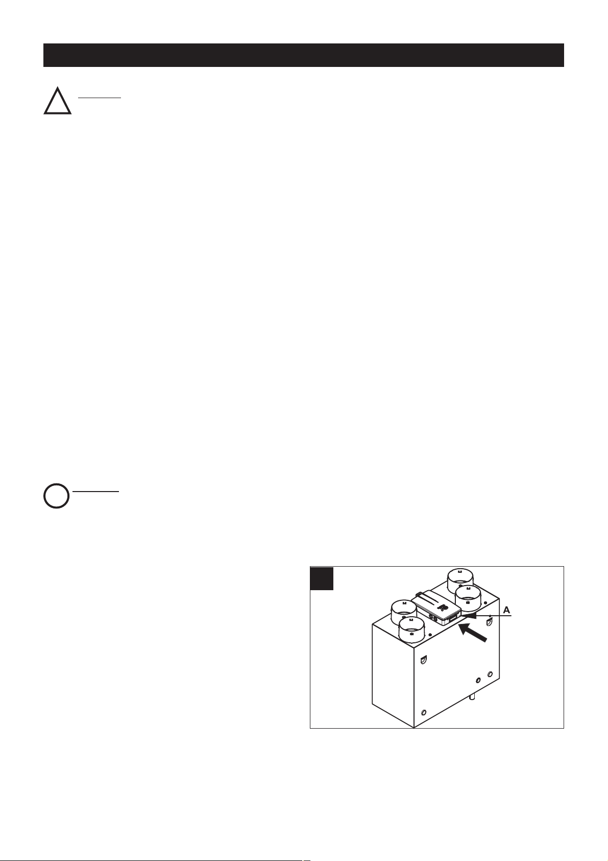
• Specifications for the power supply must correspond
to the electrical data on ID plate A (fig. 1).
ENGLISH
1
Caution:
This symbol indicates precautions that must
be taken to avoid damaging the appliance
!
Warning:
This symbol indicates precautions that must
be taken to avoid personal injury
!
Page 5
22
Items supplied
The main appliance components are as follows:
• an outer casing and front cover in painted sheet metal;
the casing houses the intake/outlet hose connections
and the electrical connection box; the casing also
houses the internal components and heat exchanger
in an air tight housing;
• internal ducts in EPP (expanded polypropylene) that
distribute ow of air while maximising heat insulation
and minimising losses.
• the plastic resin, counterow, heat exchanger whose
particular shape guarantees the highest possible
efciency in terms of heat exchange (up to 93%);
• 2 lters with G3 level particle retention;
• 2 brushless motors connected to centrifugal fans;
• the electronic circuit board that processes power
supply, appliance commands and controls;
• a temperature sensor that is essential to stop the
formation of frost on the heat exchanger;
Accessories supplied
The accessories supplied as standard include:
• 1 x condensation drainage hose coupling
• 1 x condensation drainage hose;
• 2 x rawlplugs with hooks for wall-mounting the
appliance
Installation
The appliance must be installed according to the safety
regulations currently in force in the country of
destination, and the instructions provided by this
booklet.
Prerequisites
The appliance must be tted to an internal surface or
wall of the home that is structurally sound enough to
bear its weight.
The ducts used for carrying ducting must be of the
correct size.
Ducts to and from the exterior must be thermally
insulated and not subject to vibration.
The 125 mm standard diameter inlet and outlet pipes
must be xed to the corresponding spigots on the
appliance by means of clips or some other suitable
fastening system.
Under normal operating conditions, condensation
gathers at the bottom of the appliance. In order to
dispose of it, the small hose provided must be attached
to the coupling on the underside of the appliance and
connected to a drainage hose (see Assembly).
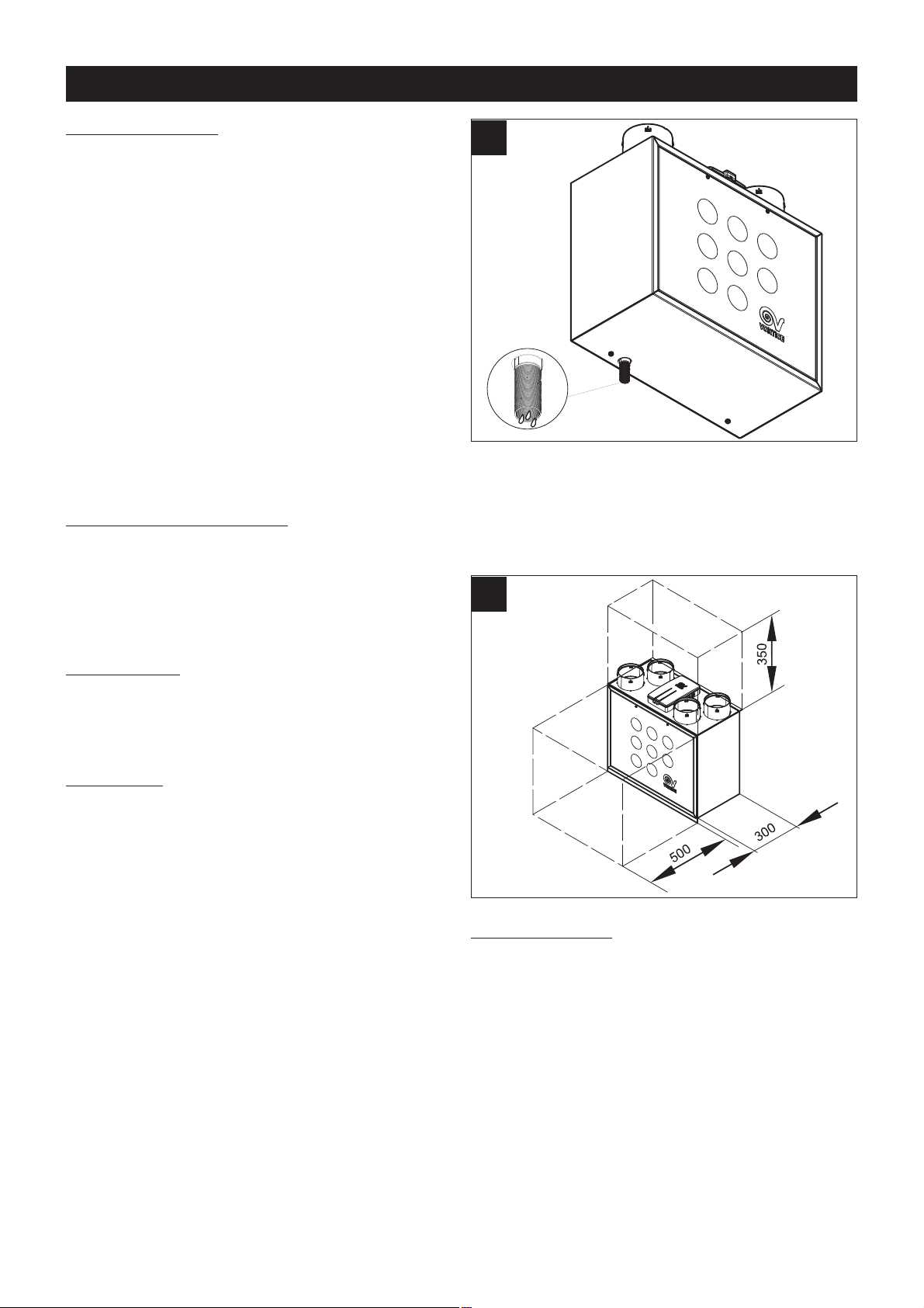
The appliance must be easily accessible for
servicing/maintenance purposes. It is important to leave
a space of at least 50 cm in front of the front panel to
facilitate the cleaning and replacement of the heat
exchanger and lters (g. 3).
Checks on delivery
On delivery, check the appliance for any faults before
proceeding with the installation. More specically:
• rstly remove it from the packaging ensuring that the
name and description shown on the box correspond;
• when the appliance has been removed from the
packaging, check that there is no visible damage then
make sure that the small condensation drainage hose
is present along with the instruction manual.
ENGLISH
2
3
Page 6
23
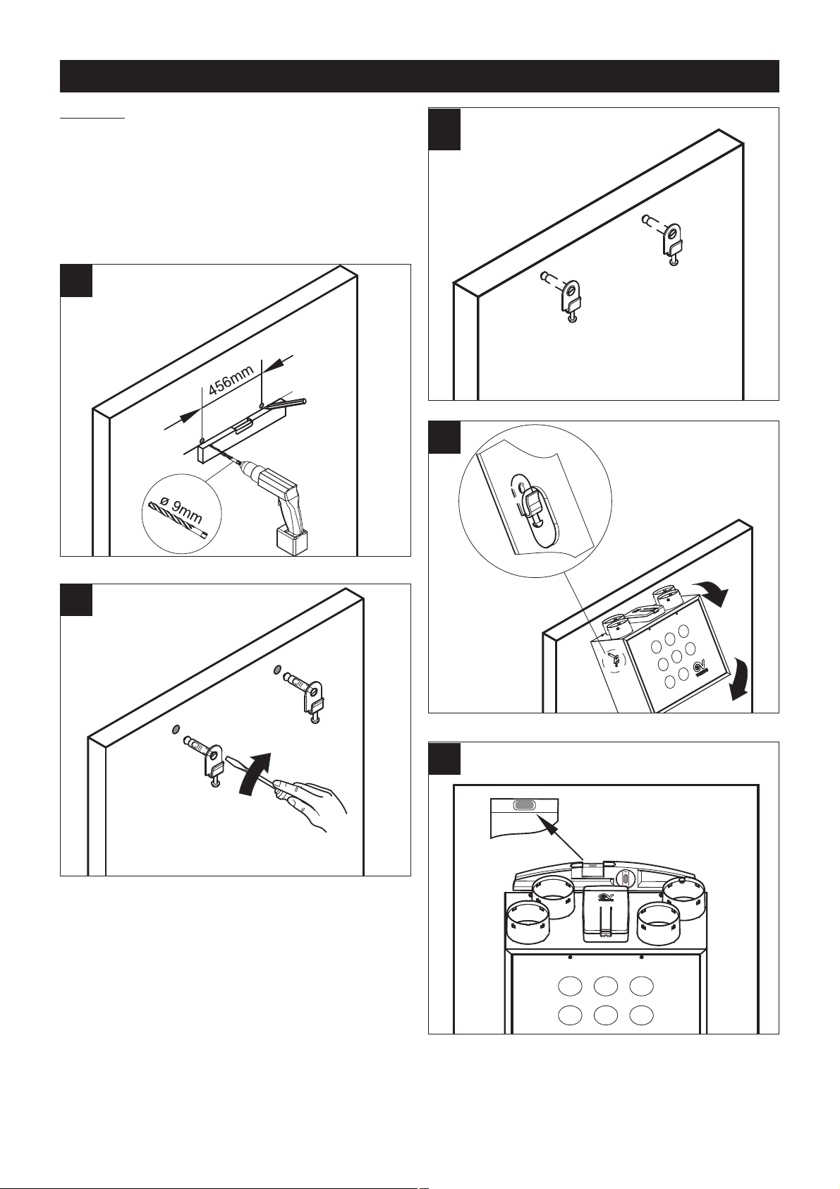
Assembly
The appliance comes with 2 rawlplugs with hooks for
wall-mounting.
Establish exactly where the appliance is to be
positioned, bearing in mind the installation
requirements.
Vertical mounting
Fix the hooks to the wall as shown in the diagrams that
follow (gs. 4,5,6,7,8).
ENGLISH
4
5
6
7
8
Page 7

24
Floor mounting (optional kit)
The appliance can be horizontally oor mounted using
the special optional kit.
Pipework connections
(g. 9).
The spigots on the appliance measure 125 mm in
diameter. Ducts may be connected to the appliance inlet
and outlets. Each connection is illustrated below with a
diagram that shows the direction of the air ow (in and
out).
Stale air outlet
(g. 10).
This outlet is used to expel stale air once it has been
treated by the heat exchanger. The ducting for this stale
air must be thermally insulated (to prevent the formation
have condensation on internal and external
components) and devices tted to absorb vibration. If
the drainage system is on the roof, it must be designed
so as to prevent the formation of condensation and the
entry of rain water.
Fresh air inlet
(g. 11)
This inlet is used for carrying fresh air from the exterior;
the duct must be thermally insulated and have devices
tted to absorb vibration. If air intake system is on the
roof, it must be designed so as to prevent the formation
of condensation and the entry of rain water.
Stale air extraction inlet
(g. 12)
This inlet carries extracted stale air from the house. The
duct needs to be thermally insulated.
ENGLISH
EXTRACT
TO
EXTERNAL
SUPPLY
FROM
EXTERNAL
EXTRACT
FROM
INTERNAL
SUPPLY
TO
INTERNAL
9
10
11
12
Page 8

25
Air outlet
(g. 13)
This outlet delivers fresh air into the house once it has
been treated in the heat exchanger.
Connecting the condensation drainage hose.
The connection point for this hose is located on the
underside of the appliance; it is to be connected
following the description below (gs.14,15,16,
17,18,19,20).
ENGLISH
13
14
15
16
17
18
Page 9

26
Condensation is drained away by connecting the hose
provided to the condensation drainage coupling.
To prevent formation of air locks a U-bend must be
created with the hose as shown in g. 21.
ENGLISH
19
20
21
Page 10

27
Electrical connections
Power supply wiring: you will need a cable with
5 X 1.5mm2 cores [4 plus earth] (g. 22)
Connecting the power supply (N1, L1 and earth) and maximum speed terminals (g. 23).
Wiring diagram with switch (g. 24)
Wiring diagram with timer (g. 25)
ENGLISH
22
24
25
23
Page 11

28
Function
Motors
The appliance is equipped with:
• two brushless motors specically designed to
guarantee very low energy consumption thanks to
their high efciency. These motors drive two
centrifugal fans which extract the stale damp air from
service rooms (kitchens, bathrooms, washrooms, etc)
and introduce fresh external air into living areas (sitting
rooms, dining rooms, bedrooms, etc.);
Heat exchanger
The two air ows, intake and extract, meet in the
appliance, (without ever actually coming into direct
contact so as not to jeopardise the quality of incoming
air) inside the heat exchanger where the warm
outgoing/extracted air passes its heat to the cold
incoming air, thus minimising the temperature variation
in the areas served.
Filters
Two G3 lters housed in the inlet and extraction ducts
close to the heat exchanger and accessible by removing
the front panel, protect the appliance from impurities in
the extracted stale air and prevent the introduction of
polluted air into the areas served by the system.
The condition of the lters can be checked by removing
the front panel and extracting them from their holders.
Replacing a standard G3 lter in the air intake system
with an optional G5 lter enhances the degree of
ltering.
Anti-frost protection
When weather conditions deteriorate and the formation
of frost on the heat exchanger walls become more likely,
the electronic circuit board automatically adjusts fan
speeds and air ow parameters.
While the automatic de-frosting cycle is in operation, the
user cannot change the appliance operating speed.
Setting fan speed
Using the switch to set fan speed (g. 26).
The appliance usually operates at minimum speed
(V
min
); the user can switch to the maximum speed
(V
max
) with the switch.
Setting fan speed using the timer (g. 27).
The fan speed can also be set using timer mode.
The keypad can be used to change the operating speed
to V
max
for 30 mins.; after this period is up, the
appliance returns to V
min.
ENGLISH
26
27
Page 12

29
Maintenance/Cleaning
Filters
The user is responsible for the periodical maintenance
of lters. The lters have to be periodically cleaned to
ensure that the appliance continues operating efciently.
They should be replaced at least once a year.
To access the lters, follow the instructions below:
• disconnect the appliance from the mains.
• remove the lters from the appliance (gs. 28,29,30)
• clean the lters using a vacuum cleaner; you are
advised to replace the lters after cleaning them a few
times but least once a year.
• ret the lters (gs. 31,32,33)
ENGLISH
28
29
30
31
Page 13

30
If the appliance remains out of use for extended periods,
we advise removing the lters to prevent any possible
damage from the build-up of condensation.
Heat exchanger
Heat exchangers do not usually need frequent cleaning.
Any need for cleaning can be determined by a high
degree of air pollution (both entering and leaving the
house) and by the lters being in poor condition.
The heat exchanger should however be replaced every
six years even if the lters have been regularly serviced.
To access the heat exchanger, follow the instructions
below:
• disconnect the appliance from the mains;
• remove the heat exchanger (gs. 34,35,36);
• clean the heat exchanger;
• ret the heat exchanger (gs. 37,38,39)
ENGLISH
32
33
34
35
36
Page 14

31
Cleaning the outside
To clean the outside of the appliance, follow the
instructions below:
• disconnect the appliance from the mains;
• only use a soft slightly damp cloth (fig. 40);
• do not use abrasive and/or corrosive products (fig. 41);
• do not use a rough and/or soaking cloth; any water
that gets inside the appliance could cause serious
damage.
ENGLISH
37
38
39
40
41
Page 15

32
Initial settings
(for installer only)
There are two ways for the installer to make the initial appliance settings:
• Remote mode using the (RF) remote control unit and
radio module.
• Appliance mode using the trimmer and dip-switch.
In addition to altering the speed settings, the initial
conguration will also include the adjustment of the air
inlet and outlet openings to and from the rooms served.
Appliance/remote control coupling
Each remote control must be initialised before use. This
activity is entrusted to the installer (for remote controls sold
separately from the product), or factory set (for remote
controls sold with the product).
The activity comprises the following steps:
a. turn the power off for at least 30 sec.;
b. turn the power back on;
c. within 60 sec. perform the procedure described below.
In detail, holding down the ENTER key for at least 3
seconds, the appliance will couple with the remote control.
Completion of coupling will be conrmed by an acoustic
signal (constant 3 second BEEP) from the remote control
itself.
Using the remote control/radio mode
(g. 42)
The initial appliance settings can be made by means of
the (RF) remote control unit and external radio module
that do not come as standard with the appliance.
N.B. Some of the functions included on the remote
control unit do not apply to this appliance.
1) Before connecting the appliance to the mains,
connect the external radio module to the electronic
circuit board and congure the dip-switch as shown
(gure 43).
In this way, the system will be able to recognise the
settings made using the remote control unit even when
it is no longer connected to the external radio module (in
effect, in this case ignoring the trimmer reading).
2) When the appliance is connected to the power supply,
the system recognises the external radio module and
keeps the motors in the OFF state.
3) Turn ON the (RF) remote control unit (fig. 44) and
check the system status (brushless motor
diagnostics, assessment of temperature sensor
reading). Subsequently, the system - unless a fault is
indicated - will start the motors at V
min
and V
max
by
default. Below are details of the settings made using
the remote control:
V
min
: set 30 (about 1100 rpm);
V
max
: set 43 (about 1360 rpm);
ENGLISH
88:88
SUMMER
MAN
AUTO
T(°C) CO2(ppm) RH(%) O
Mo Tu We Th Fr Sa Su
DISPLAY
TIMER
MODE
SET NEXT ENTER
42
43
Page 16

33
ON/OFF key (g. 44)
To turn the appliance ON and OFF. The command is only
carried out if the key is kept pressed for at least half a
second.
4) Setting the required motor speed using the remote
control unit (fig. 45).
SET key (g. 45)
For setting the minimum (V
min
) and maximum (V
max
)
speeds. To move from one parameter to the next, use
the NEXT key.
V
min
setting (g. 46):
• to display the setting, press SET, NEXT (starting from
the main menu);
• to set the value of the ashing eld with the + and keys (from 0 to 60); press ENTER or NEXT to conrm.
The display will switch to the V
max setting.
V
max
setting (g. 47):
• to display the setting, press: SET, NEXT (starting from
the main menu);
• to set the value of the ashing eld with the + and keys (from V
max
+10 to 99); press ENTER or NEXT to
conrm. The display will switch to the main screen.
5) When you have finished making the settings, turn the
remote control unit OFF (the motors will also stop) and
remove the connection with the external radio
module.
6) Disconnect the power supply to the appliance. When
restarted, the system will operate using the configured
settings. the trimmer reading will be ignored.
N.B.
After a certain period of inactivity (about 5 secs) the
remote control unit goes into “stand-by” mode; pressing
any key for a few seconds will reactivate the unit.
ENGLISH
14:38
SUMMER
Fr
DISPLAY
TIMER
MODE
SET NEXT ENTER
MAN
44
14:38
AUTO
Fr
SET
NEXT ENTER
DISPLAY
TIMER
MODE
45
SL03
46
SH50
47
Page 17

34
Manually making settings using the dip-switch
1) Before connecting the appliance to the mains,
congure the dip-switch using the following method:
(g. 48).
2) Position both the trimmers fully to the left so that they
can be turned clockwise (g. 49).
ATTENTION: do not apply excessive force to the
trimmers
3) Connect the appliance to the mains and the
appliance will start at 500 Rpm speed.
4) Set the switch for selecting speed in the position
matching the lowest setting V
min
The pre-selected conguration has to match the type of
installation (number of rooms served, length of
pipework, etc.) to be carried out.
The system is now enabled for setting with the
trimmer/dip-switch.
5) If you need to change this speed, use trimmer R1
turning it clockwise until you reach the desired setting
(g. 50).
6) Turn the switch to the position matching the selection
of the maximum operating speed (V
max
).
7) The appliance will start operating at the speed
matching the conguration of the dip-switch
selected. Select the dip-switch conguration that
presents the most suitable range of speed variations.
Turn trimmer R9 until you reach the desired value.
8) When you have nished making the settings, turn the
appliance OFF and disconnect the power supply.
N.B.
This procedure must only be carried out within one
hour of turning the appliance ON. Once this period
has elapsed, all other attempts at applying a new
speed will be ignored and the parameter set before
the appliance was turned on will be used. To apply a
new speed setting, turn the appliance OFF and turn
the trimmers anti-clockwise then reconnect the
appliance and repeat the procedure described above.
.
50
49
ENGLISH
48
Page 18

35
Activating the timer
.
In timer mode, the appliance will operate for 30 minutes
at V
max
and then return automatically to V
min
; to permit
new settings, connect the appliance to a keypad (not to
a switch).
Timer mode can be set by turning switch 1 on the dipswitch to the ON position (g. 51) .
The details above apply for other dip-switch
congurations.
N.B.
To ensure that the appliance operates properly, you are
advised to carry out the initial setting procedure using all
the steps described in the relative preselected setting
mode.
Important information on eco-compatible
disposal
IN CERTAIN EUROPEAN UNION COUNTRIES, THIS
PRODUCT DOES NOT FALL WITHIN THE
REQUIREMENTS OF THE NATIONAL LAWS
IMPLEMENTING DIRECTIVE RAEE, AND, IN THESE
COUNTRIES THE PRODUCT IS NOT SUBJECT TO
SEPARATE DISPOSAL OPERATIONS AT THE END OF
ITS WORKING LIFE.
This product complies with European Directive
2002/96/EC.
At the end of its useful life, the product
marked with the crossed out wheeled bin
must be disposed of separately from
urban waste. It must be taken to a
differentiated disposal centre for
electrical and electronic appliances or be returned to the
retailer when a new equivalent appliance is bought.
Subject to current legislation on waste disposal, the
user is legally responsible for taking the appliance at the
end of its useful life to a suitable disposal centre.
Appropriate differentiated waste collection for
subsequent recycling, treatment and environmentfriendly disposal of the discarded equipment helps to
prevent possible negative environmental and health
effects and encourages recycling of the component
materials of the equipment.
For further information about available waste disposal
systems, contact your local waste disposal service or
the shop where you bought the product.
The manufacturers and importers comply with their
responsibility for recycling, treating, and environmentally
compatible disposal of waste both directly and
collectively.
51
ENGLISH
Page 19

Table 1.1 A
Room Minimum intermittent extract rate Continuous rate
Minimum high rate Minimum low rate
Kitchen 30 l/s (adjacent to hob); Total extract rate
or 60 l/s elsewhere 13 l/s must be at least
Utility room 30 l/s 8 l/s
the whole building
Bathroom 15 l/s 8 l/s
ventilation rate in
Sanitary Accomodation 6 l/s
Table 1.1B
Table 1.1 B
Number of bedrooms in dwelling
1 2 3 4 5
Whole building ventilation rate (l/s) 13 17 21 25 29
Minimum value in any dwelling of 0,3 l/s per m
2
oor area
BUILDING REGULATIONS DOCUMENT F1 2006
CONTINUOUS MECHANICAL SUPPLY & EXTRACT
VENTILATION WITH HEAT RECOVERY
A continuous balanced mechanical central supply and extract system to
be positioned in loft or cupboard space. An integral heat exchanger
recovers a large percentage of heat energy that would have otherwise
been lost. In employing this type of system, there is no need to install
background ventilators in the dwelling.
CONTINUOUS SUPPLY AND EXTRACT
1 Determine the whole building ventilation rate from Table 1.1B
Allow for inltration by subtracting
- for multi storey dwellings: 0.04 x gross internal volume of dwelling
heated space (m3)
- for single storey dwellings: 0.06 x gross internal volume of dwelling
heated space (m3)
2 Calculate the whole dwelling extract rate at maximum operation by
adding the individual room rates for ‘minimum high rate’ from Table 1.1A
3 The required air flow rates as as follows:
Maximum Extract Rate (boost) is the greater step of 1 and 2 above.
The Minimum individual room extract rates sholuld be at least those
given in Table 1.1A for minimum high rate
Minimum air supply rate should be at least the whole building
ventilation rate in 1 above.
4 No Background ventilators are required with System 4
In addition, the minimum ventilation rate should not be less than 0.3 l/s per m2internal oor area (this includes each oor, e.g.
for a two-storey building, add the ground and rst oor areas).
This is based on two occupants in the main bedroom and a single occupant in all other bedrooms. This should be used as the
default value. If a greater level of occupance is expected, then add 4 l/s per occupant.
SYSTEM 4
36
Table 1.1 A
etar suounitnoC etar tcartxe tnettimretni muminiMmooR
Minimum high rate Minimum low rate
etar tcartxe latoT;)boh ot tnecajda( s/l 03nehctiK
tsael ta eb tsums/l 31 erehwesle s/l 06 ro
s/l 8 s/l 03 moor ytilitU
the whole building
s/l 8 s/l 51 moorhtaB
ventilation rate in
s/l 6 noitadomoccA yratinaS
Table 1.1B
Table 1.1 B
Number of bedrooms in dwelling
1 2 3 4 5
9252127131 )s/l( etar noitalitnev gnidliub elohW
Minimum value in any dwelling of 0,3 l/s per m
2
BUILDING REGULATIONS DOCUMENT F1 2006
CONTINUOUS MECHANICAL SUPPLY & EXTRACT
VENTILATION WITH HEAT RECOVERY
A continuous balanced mechanical central supply and extract system to
be positioned in loft or cupboard space. An integral heat exchanger
recovers a large percentage of heat energy that would have otherwise
been lost. In employing this type of system, there is no need to install
background ventilators in the dwelling.
CONTINUOUS SUPPLY AND EXTRACT
1 Determine the whole building ventilation rate from Table 1.1B
- for multi storey dwellings: 0.04 x gross internal volume of dwelling
heated space (m3)
- for single storey dwellings: 0.06 x gross internal volume of dwelling
heated space (m3)
2 Calculate the whole dwelling extract rate at maximum operation by
adding the individual room rates for ‘minimum high rate’ from Table 1.1A
3 The required air ow rates as as follows:
Maximum Extract Rate (boost) is the greater step of 1 and 2 above.
The Minimum individual room extract rates sholuld be at least those
given in Table 1.1A for minimum high rate
Minimum air supply rate should be at least the whole building
ventilation rate in 1 above.
4 No Background ventilators are required with System 4
In addition, the minimum ventilation rate should not be less than 0.3 l/s per m
2
This is based on two occupants in the main bedroom and a single occupant in all other bedrooms. This should be used as the
default value. If a greater level of occupance is expected, then add 4 l/s per occupant.
SYSTEM 4
BATHR OO M
BED ROO M
HEAT RE COV ERY
UNI T
KIT CHE N
LIV ING
ROO M
 Loading...