

Page 1
Libretto d’istruzioni
Instruction booklet
Notice de pose et d’entretien
Betriebsanleitung
Folleto de instrucciones
Gebruiksaanwijzing
Instruktionshäfte
TELENORDIK 5T
VORTICE ELETTROSOCIALI S.p.A.
Strada Cerca, 2 - frazione di Zoate
20067 TRIBIANO (MI)
Tel. (+39) 02-90.69.91
Fax (+39) 02-90.64.625
ITALIA
VORTICE FRANCE
72 Rue Baratte-Cholet
94106 Saint Maur Cedex
Tel. (+33) 1-55.12.50.00
Fax (+33) 1-55.12.50.01
FRANCE
VORTICE LIMITED
Beeches House - Eastern Avenue
Burton on Trent
DE13 0BB
Tel. (+44) 1283-492949
Fax (+44) 1283-544121
UNITED KINGDOM
COD. 5.371.084.755 25/05/2010
Page 2
Indice IT
Descrizione ed impiego
di Telenordik 5T . . . . . . . . . . . . . . . . 4
Attenzione . . . . . . . . . . . . . . . . . . . . 6
Avvertenza. . . . . . . . . . . . . . . . . . . . 6
Modalità d’installazione . . . . . . . . 7/30
Funzionamento e uso valido
per tutti i modelli. . . . . . . . . . . . . . . . 8
Funzione timer . . . . . . . . . . . . . . . . . 8
Manutenzione . . . . . . . . . . . . . . . . . 8
Table of Contents EN
Description and operation
of the Telenordik 5T . . . . . . . . . . . . . 4
Warning . . . . . . . . . . . . . . . . . . . . . . 9
Caution . . . . . . . . . . . . . . . . . . . . . . 9
Installation. . . . . . . . . . . . . . . . . 10/30
Functioning and instructions
for all models . . . . . . . . . . . . . . . . 11
The timer function . . . . . . . . . . . . . 11
Maintenance . . . . . . . . . . . . . . . . . 11
Index FR
Description et mode d'emploi
de Telenordik 5T. . . . . . . . . . . . . . . . 4
Attention . . . . . . . . . . . . . . . . . . . . 12
Avertissement . . . . . . . . . . . . . . . . 12
Modalités d’installation. . . . . . . . 13/30
Fonctionnement et emploi
valables pour tous les modèles. . . . 14
Fonction minuterie . . . . . . . . . . . . . 14
Entretien . . . . . . . . . . . . . . . . . . . . 14
Inhalt DE
Beschreibung und Verwendung
des Telenordik 5T. . . . . . . . . . . . . . . 4
Achtung . . . . . . . . . . . . . . . . . . . . . 15
Wichtige Hinweise . . . . . . . . . . . . . 15
Installationsarten . . . . . . . . . . . . 16/30
Funktionsweise und Bedienung
(alle Modelle) . . . . . . . . . . . . . . . . . 17
Funktion des timer . . . . . . . . . . . . . 17
Wartung . . . . . . . . . . . . . . . . . . . . . 17
Avant d’installer et raccorder le produit, lire
attentivement ces instructions. La société Vortice ne
pourra pas être tenue pour responsable des
dommages éventuels causés aux personnes ou aux
cchoses en cas d'une application incorrecte des
consignes mentionnées dans ce livret. Le respect
de toutes les indications reportées dans ce livret
garantira une longue durée de vie ainsi que la
fiabilité électrique et mécanique de cet appareil.
Conserver toujours ce livret d'instructions
Prima di installare e collegare il prodotto,
leggere attentamente queste istruzioni.
Vortice non può essere considerata
responsabile per eventuali danni a persone o
cose causate dalla non applicazione di
quanto contenuto nel libretto. Seguire tutte
le istruzioni per assicurare la sua durata e la
sua affidabilità elettrica e meccanica.
Conservare sempre questo libretto istruzioni.
Read these instructions carefully before installing
and connecting this appliance. Vortice cannot
assume any responsibility for damage to property
or personal injury resulting from failure to abide by
the instructions given in this booklet. Following
these instructions will ensure a long service life
and overall electrical and mechanical reliability.
Keep this instruction booklet in a safe place.
Antes de instalar y conectar el aparato, lea
atentamente estas instrucciones. Vortice no se hace
responsable de los posibles daños ocasionados a
personas o cosas como resultado de la
inobservancia de las indicaciones de este manual.
Siga estas instrucciones para asegurar el correcto
mantenimiento del aparato y de su fiabilidad
eléctrica y mecánica. Conservar este manual de
instrucciones.
2
Page 3
Índice ES
Descripción y uso
de Telenordik 5T. . . . . . . . . . . . . . . . 4
Atención. . . . . . . . . . . . . . . . . . . . . 18
Advertencia . . . . . . . . . . . . . . . . . . 18
Modalidades de instalación . . . . 19/30
Funcionamiento y uso válido
para todos los modelos . . . . . . . . . 20
Temporizador . . . . . . . . . . . . . . . . . 20
Mantenimiento . . . . . . . . . . . . . . . . 20
Inhoudsopgave NL
Beschrijving en gebruik
Telenordik 5T 4
Let op . . . . . . . . . . . . . . . . . . . . . . 21
Waarschuwing . . . . . . . . . . . . . . . . 21
Installatie. . . . . . . . . . . . . . . . . . 22/30
Voor alle modellen geldende
werking en gebruik . . . . . . . . . . . . . 23
Werking timer. . . . . . . . . . . . . . . . . 23
Onderhoud. . . . . . . . . . . . . . . . . . . 23
Innehållsföreckning SV
Beskrivning och bruk
av Telenordik 5T. . . . . . . . . . . . . . . . 4
Varning . . . . . . . . . . . . . . . . . . . . . 24
Observera . . . . . . . . . . . . . . . . . . . 24
Installation. . . . . . . . . . . . . . . . . 25/30
Funktion och användning som
gäller för alla modeller . . . . . . . . . . 26
Timens funktion . . . . . . . . . . . . . . . 26
Underhåll . . . . . . . . . . . . . . . . . . . . 26
Antes de instalar y conectar el aparato, lea
atentamente estas instrucciones. Vortice no se hace
responsable de los posibles daños ocasionados a
personas o cosas como resultado de la
inobservancia de las indicaciones de este manual.
Siga estas instrucciones para asegurar el correcto
mantenimiento del aparato y de su fiabilidad
eléctrica y mecánica. Conservar este manual de
instrucciones.
Lees deze handleiding aandachtig door alvorens
het product te plaatsen en aan te sluiten. Vortice
kan niet aansprakelijk worden gesteld voor
eventuele schade aan personen of zaken, ontstaan
als gevolg van het niet in acht nemen van de
aanwijzingen in dit boekje. Volg alle instructies op,
om de levensduur en de elektrische en
mechanische betrouwbaarheid te garanderen.
Bewaar deze handleiding goed.
Läs dessa anvisningar noggrant innan produkten
installeras och ansluts. Vortice åtar sig inget ansvar
för personskador eller skador på föremål som
orsakats av att anvisningarna i denna
bruksanvisning inte har beaktats. Följ alla
instruktioner så att produkten får lång hållbarhet
och elektrisk och mekanisk tillförlitlighet. Spar detta
häfte på en säker plats.
4
27
27
28/30
28
29
29
3
AR
Page 4
4
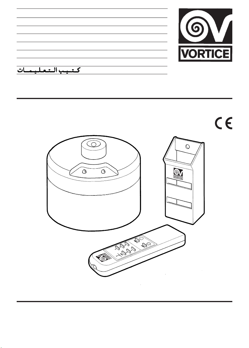
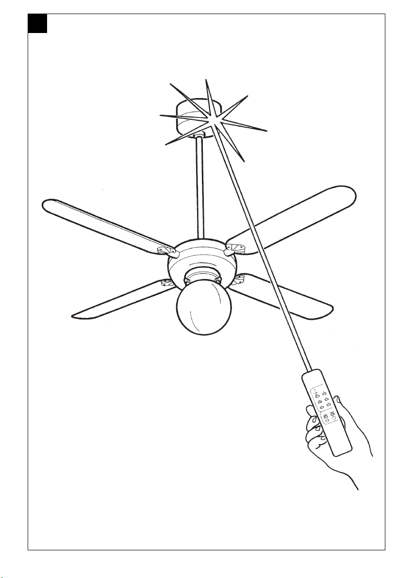
Telenordik 5T è un telecomando a raggi
infrarossi con timer per azionare a
distanza tutti i ventilatori a soffitto Vortice
con e senza luce.
Il prodotto è composto da due parti, una
ricevente e una trasmittente.Il Telenordik
5T permette di azionare il ventilatore a 5
velocità e l’accensione/spegnimento
della luce per i modelli provvisti di luce.
Inoltre il timer del Telenordik 5T può far
funzionare il ventilatore per una durata di
un’ora alla velocità prescelta.
Description and operation
of the Telenordik 5T
The Telenordik 5T is an infrared remote
control with timer, for the remote operation of all Vortice ceiling fans, with or
without light.
The product comprises two parts, a
receiver and a transmitter. The
Telenordik 5T is capable of selecting 5
different fan speeds as well as switching
the light on and off in fan models equipped with a light. The Telenordik’s timer
function can also operate ceiling fans at
a selected speed for one hour.
Description et mode d’emploi
de Telenordik 5T
Telenordik 5T est une télécommande à
rayons infrarouges avec minuterie pour
actionner à distance tous les ventilateurs
de plafond Vortice avec et sans lumière.
L’appareil comprend deux parties : une
de réception et une d’émission. La télé-
commande Telenordik 5 T permet d'actionner le ventilateur à 5 vitesses et l'allumage / extinction de la lumière pour
les modèles qui en sont pourvus. En
outre, la minuterie de la télécommande
Telenordik 5 T peut faire fonctionner le
ventilateur pendant une heure à la vitesse choisie.
Beschreibung und Verwendung
des Telenordik 5T
Telenordik 5T ist eine InfrarotFernbedienung mit Timer, um aus der
Entfernung alle Vortice-Deckenlüfter mit
und ohne Licht steuern zu können.
Das Produkt besteht aus zwei Teilen,
d.h. einem Empfangsgerät und einem
Übertragungs-gerät. Mit Hilfe der
Telenordik 5T kann man den Lüfter auf 5
Geschwindigkeiten einstellen. Bei den
Modellen mit Licht kann man das Licht
an- und ausmachen. Außerdem kann
man mit dem Timer der Telenordik 5T
den Lüfter eine Stunde lang mit der
ausgewählten Geschwindigkeit laufen
lassen.
Descripción y uso de Telenordik 5T
Telenordik 5T es un mando a distancia
por infrarrojos con temporizador para
accionar a distancia todos los ventiladores de techo Vortice con y sin luz.
El producto está compuesto por dos partes, una receptora y otra trasmisora.
Telenordik 5T permite accionar el ventilador de 5 velocidades y encender y
apagar la luz de los modelos que disponen de ella. Además, el temporizador de
Telenordik 5T puede hacer funcionar el
ventilador durante una hora a la velocidad seleccionada.
Beschrijving en gebruik van
Telenordik 5T
Telenordik 5T is een infrarode afstandsbediening met timer waarmee het
mogelijk is alle Vortice-plafondventilatoren met en zonder licht op een afstand in
werking te stellen.
Het product bestaat uit twee delen, een
ontvanger en een zender. Met Telenordik
5T is het mogelijk de ventilator op vijf
verschillende snelheden in te stellen en,
indien het model van licht is voorzien,
het licht aan en uit te doen.
Beskrivning och bruk av Telenordik 5T
Telenordik 5T är en fjärrkontroll med
infraröda strålar och med timer för att på
avstånd sätta igång alla Vortice takfläk-
tar med eller utan ljus.
Produkten består av två delar, en mottagare och en sändare. Telenordik 5T tillå-
ter igångsättning av fläkten med 5 hastigheter och tändning / släckning av ljuset
för de modeller som är försedda med
ljus. Dessutom är det möjligt att med
timern för Telenordik 5T låta fläkten fungera i en timme med förvald hastighet.
DESCRIZIONE ED IMPIEGO DI TELENORDIK 5T
EN
IT
AR
FR
DE
ES
NL
SV
Page 5
5
A
Page 6
ITALIANO
Attenzione: questo simbolo indica precauzioni per evitare danni all’utente
!
• Non usare questo prodotto per una funzione
differente da quella esposta in questo libretto.
• Dopo aver tolto il prodotto dal suo imballo, assicurarsi
della sua integrità: nel dubbio rivolgersi subito a
persona professionalmente qualificata o ad un Centro
Assistenza Tecnica autorizzato Vortice. Non lasciare
le parti dell'imballo alla portata di bambini o di
persona diversamente abile.
• L'uso di qualsiasi apparecchio elettrico comporta
l'osservanza di alcune regole fondamentali, tra le
quali: a) non deve essere toccato con mani bagnate o
umide; b) non deve essere toccato a piedi nudi;
c) non deve essere permesso ai bambini di toccare e
giocare con l'apparecchio; d) controllare la persona
diversamente abile durante l'uso dell'apparecchio.
• Riporre l’apparecchio, lontano da bambini e da
persona diversamente abile, nel momento in cui si
decide di scollegarlo dalla rete elettrica e di non
utilizzarlo più.
• Non utilizzare l'apparecchio in presenza di sostanze o
vapori infiammabili come alcool, insetticidi, benzina,
ecc.
• Questo apparecchio non è da intendersi adatto
• Non apportare modifiche di alcun genere al prodotto.
• Non lasciare l'apparecchio esposto ad agenti
atmosferici (pioggia, sole, ecc.).
• Non immergere l’apparecchio o sue parti in acqua od
in altri liquidi.
• Verificare periodicamente l'integrità dell'apparecchio.
In caso d'imperfezioni, non utilizzare l'apparecchio e
contattare subito un Centro di Assistenza Tecnica
autorizzato Vortice.
• In caso di cattivo funzionamento e/o guasto
dell'apparecchio, rivolgersi subito ad un Centro di
Assistenza Tecnica autorizzato Vortice e richiedere,
per l’eventuale riparazione, l'uso di ricambi originali
Vortice.
• Se l’apparecchio cade o riceve forti colpi farlo
verificare subito presso un Centro di Assistenza
Tecnica autorizzato Vor tice.
• L’installazione deve essere effettuata da parte di
personale professionalmente qualificato.
• L'impianto elettrico a cui è collegato il prodotto deve
essere conforme alle norme vigenti.
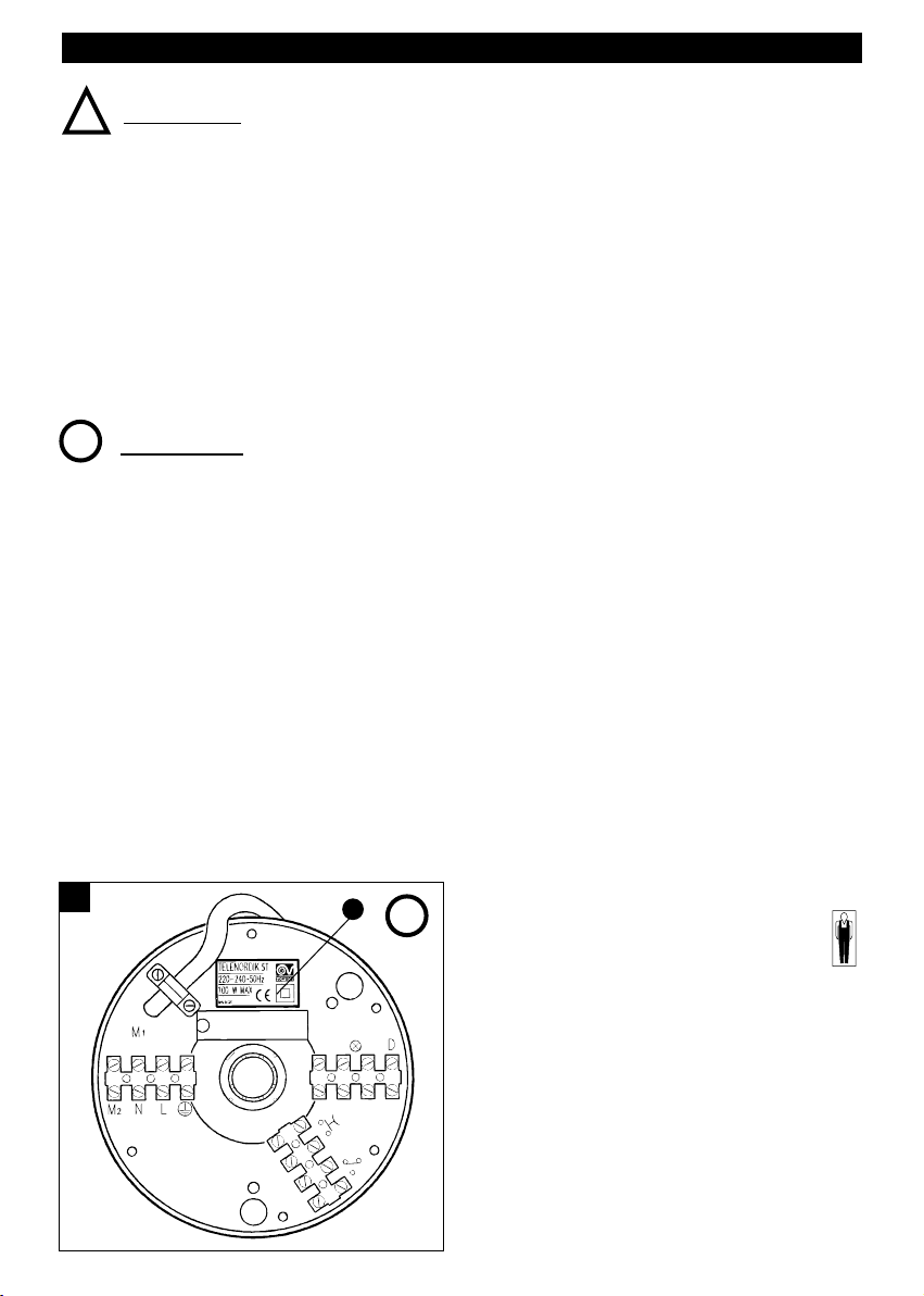
• Collegare il prodotto alla rete di alimentazione/presa
elettrica solo se:
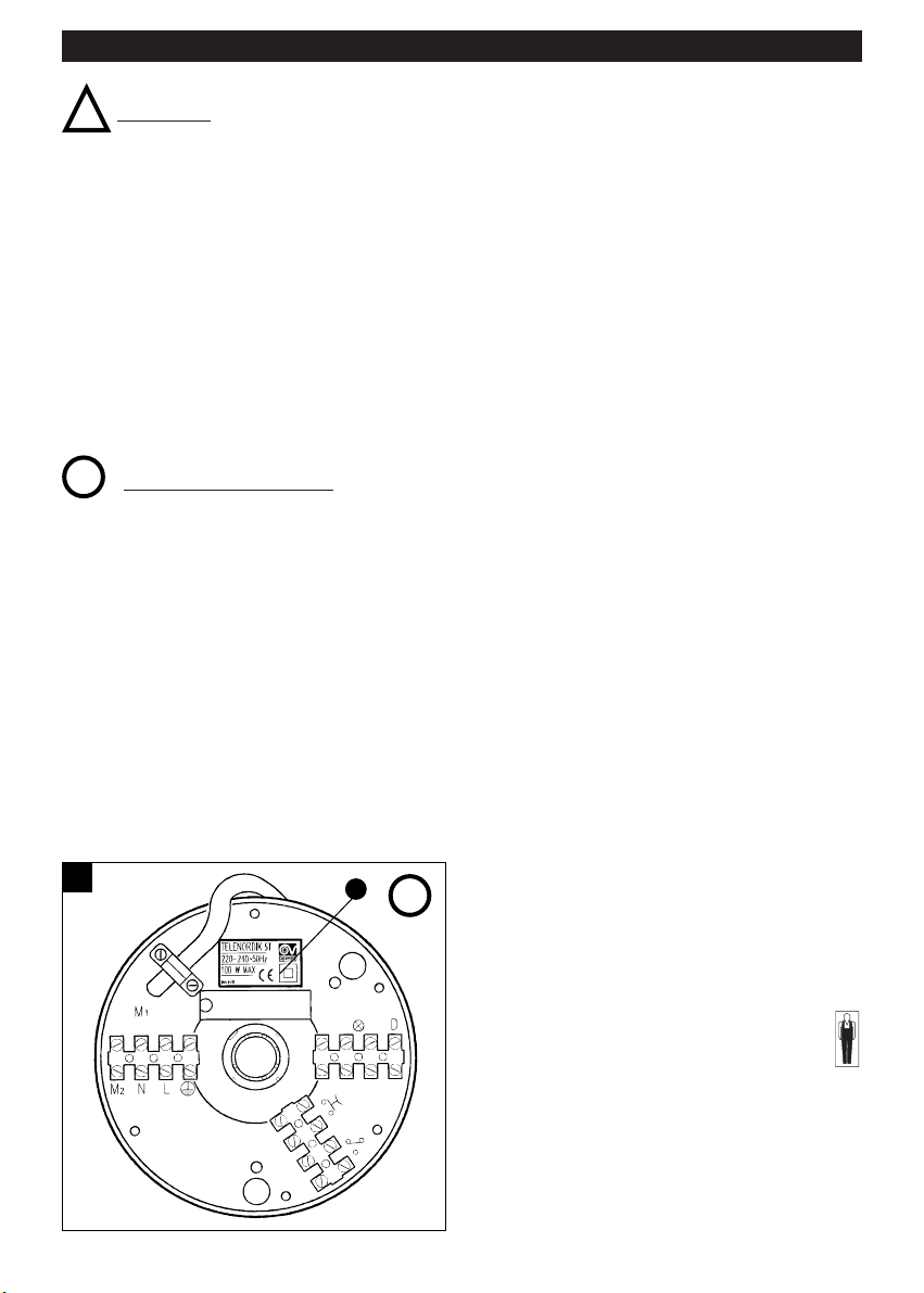
- i dati elettrici della rete corrispondono a quelli
riportati in targa (Fig. 1 - A);
- la portata dell’impianto/presa è adeguata alla sua
potenza massima.
In caso contrario rivolgersi subito a persona
professionalmente qualificata.
• Per l'installazione occorre prevedere un interruttore
onnipolare con distanza di apertura dei contatti
uguale o superiore a mm 3.
• Il cavo di collegamento interno di questo apparecchio
non deve essere sostituito dall’utente.
• Le batterie devono essere tolte dall’apparecchio
trasmettitore prima dello smaltimento ed eliminate
negli appositi contenitori di sicurezza.
• Spegnere l’interruttore generale dell’impianto quando:
a) si rileva un’anomalia di funzionamento; b) quando
si decide di eseguire una manutenzione di pulizia
esterna; c) quando si decide di non utilizzare per
brevi o lunghi periodi l'apparecchio.
• Questo simbolo significa che l’operazione
deve essere eseguita da personale
professionalmente qualificato.
Avvertenza: questo simbolo indica precauzioni per evitare inconvenienti al prodotto
!
!
1
A
all’uso da parte di persone (incluso bambini) con
ridotte capacità fisiche, sensoriali o mentali, o prive
di esperienza e conoscenza, a meno che siano state
supervisionate o istruite riguardo all’uso
dell’apparecchio da una persona responsabile della
loro sicurezza. I bambini dovrebbero essere
supervisionati per assicurarsi che non giochino con
l’apparecchio.
6
Page 7
7
ITALIANO
Modalità d’installazione (Fig. a pag. 30)
Il ricevitore è predisposto per essere montato su
tutti i ventilatori da soffitto Vortice con asta di
lunghezza massima 50 cm.
APPLICAZIONE SU NUOVI VENTILATORI
A SOFFITTO SENZA LUCE DA INSTALLARE
1) Applicare il telecomando ricevitore A sull’asta del
prodotto in sostituzione della calotta per soffitto in
dotazione (Fig. 2)
2) Inserire il cavo di collegamento C, già collegato al
ricevitore, nel tubo fino a farlo fuoriuscire dal foroB.
Nel caso di installazione del TELENORDIK 5T su un
ventilatore a soffitto nuovo non montare il passacavo
che, secondo il libretto istruzioni del ventilatore, deve
essere montato nel foro B (Fig. 2); nel caso di
installazione del TELENORDIK 5T su un ventilatore a
soffitto già installato togliere il passacavo montato nel
foro B (Fig. 2).
3) Collegare il cavo di collegamento C alla morsettiera
del ventilatore rispettando queste indicazioni: 1=
marrone, 2= blu, = giallo-verde.
APPLICAZIONE SU NUOVI VENTILATORI
A SOFFITTO CON LUCE DA INSTALLARE
1) Applicare il telecomando ricevitore A sull’asta del
prodotto in sostituzione della calotta per soffitto in
dotazione (Fig. 2).
2) Inserire il cavo di collegamento C, già collegato al
ricevitore, nel tubo fino a farlo fuoriuscire dal foro B.
Nel caso di installazione del TELENORDIK 5T su un
ventilatore a soffitto nuovo non montare il passacavo
che, secondo il libretto istruzioni del ventilatore, deve
essere montato nel foro B (Fig. 2); nel caso di
installazione del TELENORDIK 5T su un ventilatore a
soffitto già installato togliere il passacavo montato nel
foro B (Fig. 2).
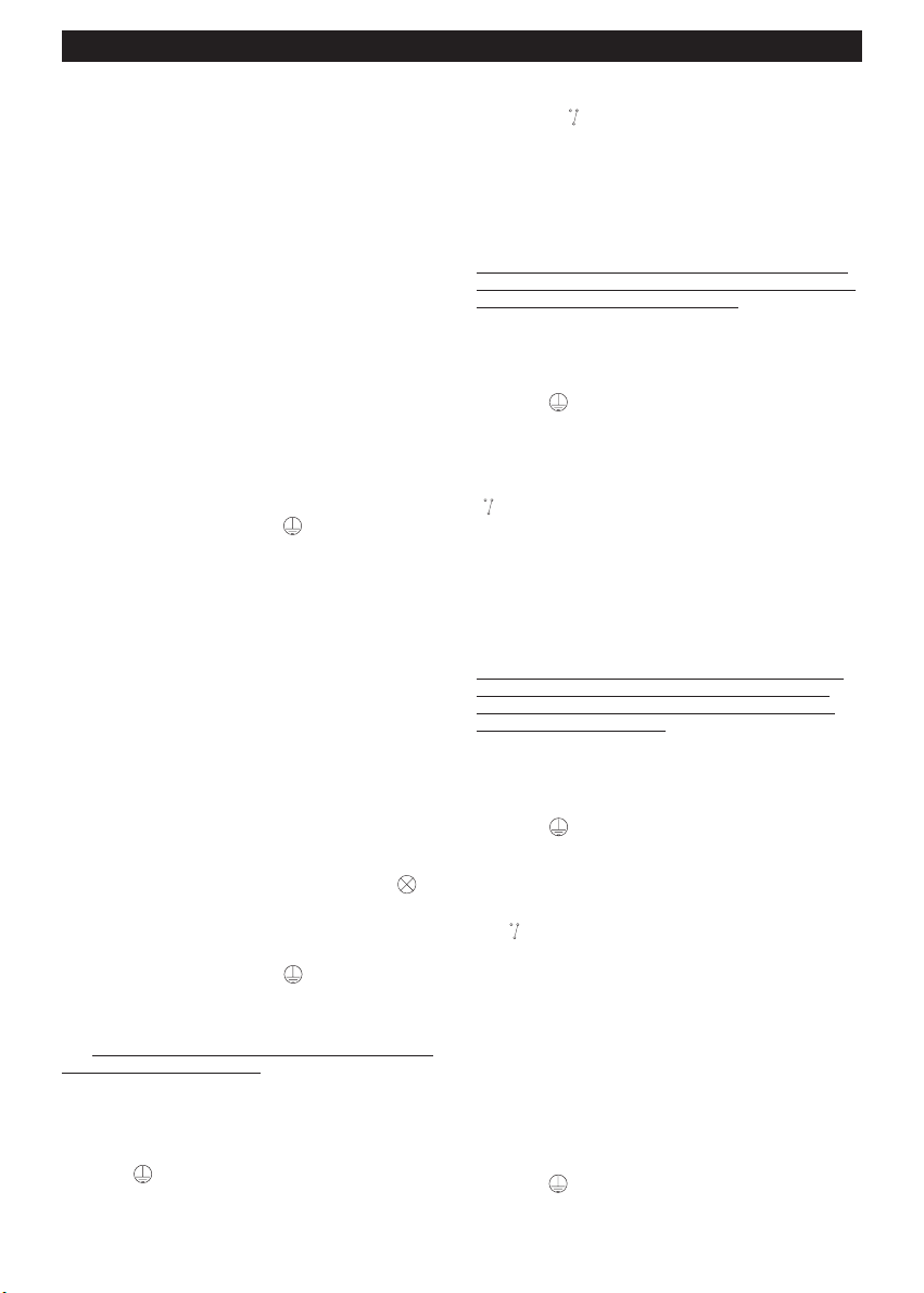
3) Scollegare i cavetti rosso e nero dalla morsettiera H
(schema 1 - Fig. 6) e collegarli ai morsetti
contrassegnati dal simbolo (schema generale Fig. 7).
4) Collegare il cavo di collegamento C alla morsettiera
del ventilatore rispettando le seguenti indicazioni: 1=
marrone, 2= blu, = giallo-verde, 3= rosso e 4=
nero.
5) Proseguire con il collegamento elettrico,
scegliendo uno degli schemi sotto riportati, seguendo
scrupolosamente le seguenti istruzioni:
Schema A: accensione e spegnimento luce
solamente per mezzo del telecomando
trasmettitore
A) Collegare i conduttori della linea di alimentazione
alla morsettiera E rispettando i simboli L, N,
riportati sul fondo del ricevitore in prossimità della
morsettiera stessa (schema A - Fig. 8).
B) Collegare il cavetto in dotazione nel sacchetto
accessori tra il morsetto contrassegnato con la
lettera D della morsettiera H ed il morsetto
contrassegnato con il simbolo della morsettiera F
(riferimento morsetto terminale cavetto grigio schema A - Fig. 8).
Schema B: accensione e spegnimento luce per
mezzo del telecomando trasmettitore e di un
deviatore sulla parete del locale (impianto
esistente con due deviatori)
Il telecomando r
icevitore deve essere collegato in
sostituzione al deviatore al cui morsetto centrale è
collegato uno dei due conduttori della lampada
esistente.
A) Scollegare la lampada o lampadario W esistente
nel locale nei punti 4 e 5 (schema B - Fig. 9).
B) Collegare i conduttori della linea di alimentazione
alla morsettiera E rispettando i simboli L, N,
riportati sul fondo del ricevitore in prossimità della morsettiera stessa (schema B1 - Fig. 10).
C) Scollegare dal deviatore V i cavetti collegati ai
punti 1 e 3 e collegarli, prolungandoli, ai morsetti
contrassegnati col simbolo della morsettiera F
(schema B1 - Fig. 10).
Schema C: accensione e spegnimento luce per
mezzo del telecomando trasmettitore e di un
deviatore ed uno o più invertitori sulla parete del
locale (impianto esistente con due deviatori ed
uno o più invertitori)
Il telecomando r
icevitore deve essere collegato in
sostituzione al deviatore al cui morsetto centrale è
collegato uno dei due conduttori della lampada
esistente.
A) Scollegare la lampada o lampadario W esistente
nel locale nei punti 4 e 5 (schema C - Fig. 11).
B) Collegare i conduttori della linea di alimentazione
alla morsettiera E rispettando i simboli L, N,
riportati sul fondo del ricevitore in prossimità della morsettiera stessa (schema C1 - Fig. 12).
C) Scollegare dal deviatore V i cavetti collegati ai
punti 1 e 3 e collegarli, prolungandoli, ai morsetti
contrassegnati col simbolo della morsettiera F
(schema C1 - Fig. 12).
Schema D: accensione e spegnimento luce per
mezzo del telecomando trasmettitore e di uno o
più pulsanti (impianto esistente)
A) Scollegare la lampada o lampadario W esistente
nel locale nei punti 4 e 5 (schema D - Fig. 13).
B) Scollegare dalla rete di alimentazione tutti i
pulsanti ed i relè dell’impianto nei punti 6, 7 e 8
(schema D - Fig. 13).
C) Collegare i conduttori della linea di alimentazione
alla morsettiera E rispettando i simboli L, N, riportati
sul fondo del ricevitore in prossimità della
morsettiera stessa (schema D1 - Fig. 14).
D) Collegare il cavetto in dotazione nel sacchetto
accessori tra il morsetto contrassegnato con la lettera
D della morsettiera H ed il morsetto contrassegnato
con il simbolo della morsettiera F (riferimento
morsetto terminale grigio - schema D1 - Fig. 14).
E) Collegare tutti i pulsanti dell’impianto in parallelo ai
morsetti contrassegnati col simbolo della
morsettiera F ( schema D1 - Fig. 14).
Schema E: accensione e spegnimento luce per
mezzo del telecomando trasmettitore e di uno o
più pulsanti (impianto nuovo)
A) Collegare i conduttori della linea di alimentazione
alla morsettiera E rispettando i simboli L, N,
Page 8
8
riportati sul fondo del ricevitore in prossimità della
morsettiera stessa (schema D1 - Fig. 14).
B) Collegare il cavetto in dotazione nel sacchetto
accessori tra il morsetto contrassegnato con la lettera
D della morsettiera H ed il morsetto contrassegnato
con il simbolo della morsettiera F (riferimento
morsetto terminale cavetto grigio - schema D1 Fig. 14).
C) Collegare tutti i pulsanti dell’impianto in parallelo ai
morsetti contrassegnati col
simbolo (schema D1 -
Fig. 14).
6) Posizionare il telecomando ricevitore A contro il
soffitto od in prossimità dello stesso e serrare la
vite M senza eccedere (Fig. 2).
7) Il contenitore del telecomando trasmettitore si può
applicare a parete eseguendo un foro ∅ 6 mm ed
inserendo il tassello in dotazione (Fig. 4).
Attenzione
Installando il telecomando la scatola comandi deve
essere eliminata; pertanto bisogna ripristinare il
collegamento della linea.
Si consiglia di fissare il ricevitore con i due led
luminosi orientati a vista verso la zona dell’ambiente
da dove più frequentemente si userà il trasmettitore.
Funzionamento ed uso valido
per tutti i modelli
1) Eseguito il collegamento elettrico e montato il ven-
tilatore a soffitto, chiudere l’interruttore onnipolare: un
primo segnalatore luminoso a led si accende per
indicare che il telecomando è sotto tensione.
2) Inserire nel vano sul retro del trasmettitore (Fig. 5)
due batterie AAA 1,5 V di tipo alcalino, rispettando le
polarità indicate.
3) Provare il funzionamento del ventilatore a soffitto,
premendo uno dei bottoni (1 - 2 - 3 - 4 - 5) del
telecomando, a seconda della velocità.
4) Provare l’accensione e spegnimento della luce del
ventilatore (se provvisto), premendo il tasto del
trasmettitore indicato con .
5) Premere il tasto “OFF” del trasmettitore per
arrestare il ventilatore; eventualmente premere
nuovamente il tasto indicato con per spegnere la
luce del ventilatore.
Controllare anche gli eventuali deviatori, invertitori e
pulsanti, assicurandosi che tutto l’impianto funzioni
regolarmente.
Funzione timer
Il prodotto è dotato di una funzione timer che ne
permette il funzionamento alla velocità prescelta per
la durata di 1 ora.
Per far partire il timer si deve premere il tasto timer.
L’accensione del led verde sul ricevitore indica
l’avvenuto inserimento. Il led verde rimane acceso per
l’intera durata della funzione timer (1 ora).
Quindi si spegne.
Per una nuova timerizzazione selezionare
nuovamente la funzione premendo il tasto del timer.
Se dopo aver azionato la funzione timer su una
velocità si volesse cambiare velocità questo è
possibile e non comporta nessuna variazione del
tempo di timerizzazione, che rimane comunque
di 1 ora.
Se si desidera interrompere prima il tempo
selezionato con la funzione timer è sufficiente
premere il tasto off.
Con lo spegnimento, mediante il tasto off, si
disattivano tutte le funzioni.
Manutenzione
Prima di ogni intervento di manutenzione disinserire
l’apparecchio dalla rete.
Il telecomando non richiede particolare manutenzione.
Non usare polveri, sostanze abrasive o solventi per
pulire le superfici in vista.
Consigli utili
La portata del segnale del telecomando (con batteria
del trasmettitore perfettamente carica) è di c.a. 13 mt.
Nel caso d’installazioni multiple di ventilatori si
consiglia di montare gli apparecchi ad una distanza di
almeno 3 mt. l’uno dall’altro.
Qualora il trasmettitore non riuscisse ad azionare il
ventilatore, controllare lo stato d’efficienza delle
batterie dello stesso e, se necessario, provvedere alla
loro sostituzione (per smaltimento batterie vedere il
paragrafo avvertenze particolari).
ITALIANO
Page 9

9
ENGLISH
• Do not use this appliance for purposes other than
those described in this booklet.
• After removing the appliance from its packaging,
ensure that it is complete and undamaged.
If in doubt contact a professionally qualified electrician
or Vortice*. Do not leave packaging within the reach
of children or the infirm.
• Certain fundamental rules must be observed when
using any electrical appliance, including: a) never
touch appliances with wet or damp hands; b) never
touch appliances while barefoot; c) do not allow
young children or infirm persons to use the appliance
without supervision; d) supervise young children to
ensure that they do not play with the appliance.
• Store the appliance out of the reach of children and
infirm persons if you decide to disconnect it from the
power supply and no longer use it.
• Do not operate the appliance in the presence of
inflammable substances or vapours (alcohol,
insecticides, petrol, etc.).
Warning! this symbol indicates precautions that must be taken to avoid injury
!
• Do not make modifications of any kind to this
appliance.
• Do not expose this appliance to the weather (rain,
sun, etc.).
• Do not immerse the appliance or any of its parts in
water or other liquids.
• Regularly inspect the appliance for visible defects.
If any faults are found, do not operate the appliance;
contact Vortice* immediately.
• If the appliance malfunctions or develops a fault,
contact Vortice* immediately. Ensure that only
genuine original Vortice spares are used for any
repairs.
• Should the appliance be dropped or suffer a heavy
blow, have it checked immediately by Vortice*.
• The appliance must be installed and the fuse
changed if necessary by a professionally qualified
electrician only.
• Ensure that the electrical system to which the
appliance is connected complies with applicable
standards.
• Only connect the appliance to the power
supply/socket if:
- the mains power specifications correspond to those
on the data plate (fig. 1-A);
- the electrical power supply/socket provides the
maximum electrical power required by the appliance.
If this is not the case, arrange for a qualified
electrician to make the necessary modifications.
• Use a multi-polar switch with minimum contact gaps
of 3 mm to install the appliance.
• The internal connection cable in this appliance must
never be replaced by the user.
• Remove the batteries and dispose of them at a
designated battery collection point before scrapping
the transmitter.
• Switch off the appliance at the main switch: a) if the
appliance does not function correctly; b) before
cleaning the outside of the appliance, c) if the
appliance is not to be used for any length of time.
• This symbol indicates that the operation
must be carried out by a suitably qualified
person.
* (or an authorised Service Centre if you are outside
the UK-Ireland territory)
Caution! this symbol indicates precautions that must be taken to avoid damaging the appliance
!
!
1
A
Page 10
10
ENGLISH
Installation (See the figure on page 30)
The receiver is designed for fitting on all Vortice
ceiling fans with rods not exceeding 50 cm in
length.
FITTING TO A NEW CEILING FAN WHEN NO
LIGHT IS TO BE INSTALLED.
1) Fit the remote control receiver A to the ceiling fan
rod in place of the ceiling cover provided (fig. 2).
2) Push the connection cable C (already connected to
the receiver) through the tube until it comes out of
hole B. If installing TELENORDIK 5T on a new ceiling
fan, do not fit the cable guide that the fan’s own
instruction booklet tells you to fit in hole B (fig. 2). If
fitting TELENORDIK 5T on an existing ceiling fan,
remove the cable guide from the hole B (fig. 2).
3) Connect the connection cable C to the fan
terminals. Respect the colour scheme: 1 = brown;
2 = blue;
= yellow-green.
FITTING TO A NEW CEILING FAN WHEN A LIGHT
IS TO BE INSTALLED.
1) Fit the remote control receiver A to the ceiling fan
rod in place of the ceiling cover provided (fig. 2).
2) Push the connection cable C (already connected to
the receiver) through the tube until it comes out of
hole B. If installing TELENORDIK 5T on a new ceiling
fan, do not fit the cable guide that the fan’s own
instruction booklet tells you to fit in hole B (fig. 2). If
fitting TELENORDIK 5T on an existing ceiling fan,
remove the cable guide from the hole B (fig. 2).
3) Disconnect the red and black wires from the
terminal board H, (diagram 1, fig. 6), and connect
them to the terminals marked with the symbol
(overall diagram, fig. 7).
4) Connect the connection cable C to the fan
terminals. Respect the colour scheme: 1 = brown; 2 =
blue; = yellow-green; 3 = red; 4 = black.
5) Continue the electrical connections according to
one of the diagrams given below. Follow these
instructions very carefully.
Diagram A: to turn the light ON and OFF using
just the remote control.
A) Connect the mains power cable to the terminal
board E, respecting the symbols L, N and at the
bottom of the receiver near the terminal
board (diagram A, fig. 8).
B) Connect the cable provided in the accessory bag
between terminal D of terminal board H and the
terminal marked with symbol on terminal board F
(see the grey wire terminal in diagram A, fig. 8).
Diagram B: to turn the light ON and OFF using the
remote control and a wall switch (where two
switches are already installed).
Connect up the remote control receiv
er in place of the
switch whose centre terminal is connected to one of
the two wires to the light.
A) Disconnect the room’s lamp or light fixture W at
points 4 and 5 (diagram B, fig. 9).
B) Connect the mains power cable to the terminal
block E, respecting the symbols L, N and at the
bottom of the receiver near the terminal board
(diagram B1, fig. 10).
C) Disconnect the wires connected to points 1 and 3
from the switch V, extend and connect them to the
terminals marked with the symbol
on terminal
board F (diagram B1, fig. 10).
Diagram C: to turn the light ON and OFF using the
remote control, one standard wall switch and one
or more changeover wall switches (where two
switches and one or more changeover switches
are already installed).
Connect up the remote control receiv
er in place of the
switch whose centre terminal is connected to one of
the two wires to the light.
A) Disconnect the room’s lamp or light fixture W at
points 4 and 5 (diagram C, fig. 11).
B) Connect the mains power cable to the terminal
block E, respecting the symbols L, N and at the
bottom of the receiver near the terminal board
(diagram C1, fig. 12).
C) Disconnect the wires connected to points 1 and 3
from the switch V, extend and connect them to the
terminals marked with the symbol on terminal
board F (diagram C1, fig.12).
Diagram D: to turn the light ON and OFF using the
remote control and one or more push-buttons
(already installed).
A) Disconnect the room’s lamp or light fixture W at
points 4 and 5 (diagram D, fig. 13).
B) Disconnect all the push-buttons and relays from the
mains power at points 6, 7 and 8 (diagram D, fig. 13).
C) Connect the mains power cable to the terminal
block E, respecting the symbols L, N and at the
bottom of the receiver near the terminal board
(Diagram D1, fig. 14).
D) Connect the cable provided in the accessory bag
between terminal D of terminal board H and the
terminal marked with the symbol on terminal board
F (see the grey wire terminal in diagram D1, fig. 14).
E) Connect all the push-buttons in parallel to the
terminals marked with the symbol on terminal
board F (diagram D1, fig. 14).
Diagram E: to turn the light ON and OFF using the
remote control and one or more push-buttons
(new system).
A) Connect the mains power cable to the terminal
block E, respecting the symbols L, N and at the
bottom of the receiver near the terminal board
(diagram D1, fig.14).
B) Connect the cable provided in the accessory bag
between terminal D of terminal board H and the
terminal marked with the symbol on terminal board
F (see the grey wire terminal in diagram D1, fig. 14).
C) Connect all the push-buttons in parallel to the
terminals marked with the symbol (diagram D1,
fig. 14).
6) Locate the remote control receiver A on or near the
ceiling and tighten screw M (fig. 2). Do not overtighten.
Page 11
11
7) The remote control receiver box can also be wall
mounted. To do so, drill an 8 mm hole in the wall and
insert the plug provided (fig. 4).
Important
When the remote control is installed, the control box
must be eliminated and the relevant connections
restored.
Install the receiver with the two LEDs facing the part
of the room from which the transmitter will be most
frequently used.
Functioning and instructions for all
models
1) Once you have made all the necessary
connections and fitted the ceiling fan, turn on the
multi-polar switch. The remote control function LED
will come on.
2) Insert two 1.5 V AAA batteries in the battery
compartment in the rear of the transmitter. Respect
the battery polarity as shown.
3) Press the buttons (1 – 2 – 3 – 4 – 5) on the remote
control to test the functioning of the ceiling fan at the
various speeds.
4) Press the light button (marked with the symbol)
on the remote control to test turning the light (if fitted)
ON and OFF.
5) Press the “OFF” button on the remote control to
turn the fan OFF. Press the light button (marked with
the symbol) on the remote control to turn the light
OFF again.
Also test all the switches, changeover switches and
push-buttons in the system to ensure that they are
functioning properly.
The timer function
The Telenordik T5 features a timer function that
permits fan operation at the selected speed for one
hour.
To start the timer, simply press the timer button.
The green LED on the receiver lights to show that the
timer has been activated. This LED remains lit for the
duration of the timer function (1 hour) then goes out.
To repeat timed fan operation, press the timer button
again.
You can change fan speed even with the timer active
without affecting fan operation time (which is always 1
hour).
To stop the fan before the end of the timed period,
simply press the OFF button.
Pressing the OFF button deactivates all functions.
Maintenance
Disconnect the appliance from the mains supply
before performing any maintenance operations.
The remote control does not require any particular
maintenance.
Do not use abrasive powders or solvents to clean
visible surfaces.
Useful hints
The range of the remote control signal (with fully
charged batteries in the transmitter) is about 13
metres.
If you are installing more than one ceiling fan, leave a
gap of at least 3 metres between one fan and the
next.
If the remote control transmitter fails to operate the
fan, check the transmitter batteries and change them
as necessary. See the note on disposal of batteries in
the Caution section.
ENGLISH
Page 12

12
FRANÇAIS
• Ne pas utiliser cet appareil pour un usage autre que
celui décrit dans ce livret.
• Contrôler l'intégrité de l'appareil après l'avoir sorti de
son emballage : dans le doute, s'adresser
immédiatement à une personne professionnellement
qualifiée ou à un Service après-vente agréé Vortice.
Placer les éléments de l'emballage hors de la portée
des enfants ou des personnes handicapées.
• L’utilisation de tout appareil électrique implique le
respect de quelques règles fondamentales dont,
entre autres : a) ne pas toucher l'appareil avec les
mains mouillées ou humides ; b) ne pas le toucher
pieds nus ; c) interdire aux enfants de le toucher et de
jouer avec l'appareil ; d) contrôler la personne
handicapée durant l'utilisation de l'appareil.
• Ranger l'appareil hors de portée des enfants et des
personnes handicapées après l'avoir débranché du
réseau électrique pour ne plus l'utiliser.
• Ne pas utiliser l'appareil en présence de substances
ou de vapeurs inflammables telles que l'alcool, les
insecticides, l'essence, etc.
Attention : ce symbole indique la nécessité de prendre quelques précautions
pour la sécurité de l'utilisateur
!
• Ne modifier l'appareil en aucune façon.
• Ne pas exposer l'appareil aux agents atmosphériques
(pluie, soleil, etc.).
• Ne pas immerger l'appareil ou ses parties dans l'eau
ou dans d'autres liquides.
• Vérifier périodiquement si l'appareil est en bon état.
En cas de défectuosité, ne pas utiliser l'appareil et
contacter immédiatement un Service après-vente
agréé Vortice.
• En cas de dysfonctionnement et/ou de panne,
s'adresser immédiatement à un Service aprèsvente
agréé Vortice et exiger, en cas de réparation, l'emploi
de pièces détachées originales Vortice.
• Si l'appareil tombe ou reçoit des coups violents, le
faire vérifier immédiatement auprès d'un Service
après-vente agréé Vortice.
• L'installation et l'éventuel remplacement du fusible de
l'appareil doivent être effectués par du personnel
professionnellement qualifié.
• L'installation électrique à laquelle l'appareil est
branché doit être conforme aux normes en vigueur.
• Relier l’appareil au réseau d’alimentation/à la prise
électrique uniquement si :
- les données électriques du réseau correspondent à
celles qui sont reportées sur la plaque d’identification
(Fig. 1 - A) ;
- la tension du secteur/de la prise est adaptée à sa
puissance maximum. Dans le cas contraire,
s’adresser immédiatement à du personnel
professionnellement qualifié.
• Pour son installation, prévoir un interrupteur
omnipolaire dont la distance d'ouverture des contacts
est supérieure ou égale à 3 mm.
• Le câble de branchement interne de cet appareil ne
doit pas être remplacé par l'utilisateur.
• Les piles doivent être enlevées et éliminées dans les
conteneurs spéciaux de sécurité avant l'élimination
de l'appareil émetteur.
• Couper l'interrupteur général de l'installation dans les
cas suivants : a) dysfonctionnement ; b) pour
procéder à un nettoyage extérieur ; c) lorsque
l'appareil n'est pas utilisé pendant une longue
période.
• Ce symbole signifie que l'opération doit
être exécutée par du personnel
professionnellement qualifié.
Avertissement : ce symbole indique de prendre quelques précautions pour la sécurité
du produit
!
!
1
A
Page 13

13
FRANÇAIS
Modalités d’installation (Fig. page 30)
Le récepteur est prédisposé pour être monté sur
tous les ventilateurs de plafond Vortice avec tige
de 500 cm de long maximum.
APPLICATION SUR LES NOUVEAUX
VENTILATEURS DE PLAFOND SANS LUMIERE A
INSTALLER
1) Appliquer la télécommande réceptrice A sur la tige
du produit à la place de la calotte pour plafond fournie
(Fig. 2).
2) Introduire le câble de branchement C, déjà relié au
récepteur, dans le tube jusqu’à ce qu’il sorte par
l’orifice B. En cas d’installation de la TELENORDIK 5T
sur un ventilateur neuf de plafond, ne pas monter la
bague qui, selon la notice du ventilateur, doit être
montée dans l’orifice B (Fig.2) ; en cas
d’installation de la TELENORDIK 5T sur un ventilateur
de plafond existant, enlever la bague montée dans
l’orifice B (Fig.2).
3) Relier le câble C au bornier du ventilateur en
respectant les indications suivantes : 1 = marron, 2 =
bleu, = jaune-vert.
APPLICATION SUR DE NOUVEAUX
VENTILATEURS DE PLAFOND AVEC LUMIERE A
INSTALLER
1) Appliquer la télécommande réceptrice A sur la tige
du produit à la place de la calotte pour plafond
fournie.
2) Insérer le câble C, déjà relié au récepteur, dans le
tube jusqu’à ce qu’il sorte par l’orifice B. En cas
d’installation de la TELENORDIK 5T sur un ventilateur
neuf de plafond, ne pas monter la bague qui, selon la
notice du ventilateur, doit être montée dans l’orifice B
(Fig. 2) ; en cas d’installation de la TELENORDIK 5T
sur un ventilateur de plafond existant, enlever la
bague montée dans l’orifice B (Fig. 2).
3) Déconnecter les fils rouge et noir du bornier H
(Schéma 1 - Fig. 6) et les relier aux bornes portant le
symbole (Schéma général - Fig. 7).
4) Relier le câble C au bornier du ventilateur en
respectant les indications suivantes : 1= marron,
2= bleu, = jaune-vert, 3 = rouge et 4 = noir.
5) Réaliser le branchement électrique en choisissant
l’un des schémas ci-dessous, en suiv
ant
scrupuleusement les instructions fournies :
Schéma A Fig. 10 : allumage et extinction lumière
seulement au moyen de la télécommande
émettrice
A) Relier les conducteurs de la ligne d’alimentation au
bornier E en respectant les symboles L, N,
indiqués sur le fond du récepteur à proximité dudit
bornier (schéma A - Fig. 8).
B) Relier le fil fourni dans le sachet d’accessoires
entre la borne portant la lettre D du bornier H et la
borne portant le symbole du bornier F (référence
borne terminale fil gris - schéma A - Fig. B).
Schéma B : allumage et extinction lumière au
moyen de la télécommande émettrice et d’un
déviateur sur le mur de la pièce (installation
existante avec deux déviateurs)
La télécommande réceptr
ice doit être reliée à la place
du déviateur dont la borne centrale est reliée à l’un
des deux conducteurs de la lampe existante.
A) Déconnecter le lampe ou le lampadaire W présent
dans la pièce aux points 4 et 5 (Schéma B - Fig.9).
B) Relier les conducteurs de la ligne d’alimentation au
bornier E en respectant les symboles L, N, indiqués
sur le fond du récepteur à proximité dudit bornier
(Schéma B1 - Fig.10).
C) Déconnecter du déviateur V les fils reliés aux
points 1 et 3 et les relier, en les rallongeant, aux
bornes portant le symbole du bornier F (Schéma B1 Fig.10).
Schéma C : allumage et extinction lumière au
moyen de la télécommande émettrice, d’un
déviateur et d’un ou plusieurs inverseurs sur le
mur de la pièce (installation existante avec deux
déviateurs et un ou plusieurs inverseurs)
La télécommande réceptr
ice doit être reliée à la place
du déviateur dont la borne centrale est reliée à l’un
des deux conducteurs de la lampe existante.
A) Déconnecter la lampe ou le lampadaire W existant
dans la pièce aux points 4 et 5 (Schéma C - Fig.11).
B) Relier les conducteurs de la ligne d’alimentation au
bornier E en respectant les symboles L, N,
indiqués sur le fond du récepteur à proximité dudit
bornier (Schéma C1 - Fig.12).
C) Déconnecter du déviateur V les fils reliés aux
points 1 et 3 et les relier, en les rallongeant, aux
bornes portant le symbole du bornier F (Schéma
C1 - Fig.12).
Schéma D : allumage et extinction lumière au
moyen de la télécommande émettrice et d’un ou
plusieurs boutons (installation existante)
A) Déconnecter la lampe ou le lampadaire W existant
dans la pièce aux points 4 et 5 (Schéma D - Fig.13).
B) Déconnecter du réseau d’alimentation tous les
boutons et les relais de l’installation aux points 6, 7 et
8 (Schéma D - Fig.13).
C) Relier les conducteurs de la ligne d’alimentation au
bornier E en respectant les symboles L, N,
indiqués sur le fond du récepteur à proximité dudit
bornier (Schéma D1 - Fig.14).
D) Relier le fil fourni dans le sachet d’accessoires
entre la borne portant la lettre D du bornier H et la
borne portant le symbole du bornier F (référence
borne terminale grise - Schéma D1 - Fig.14).
E) Relier tous les boutons de l’installation en parallèle
aux bornes portant le symbole du bornier F
(Schéma D1 - Fig.14).
Schéma E : allumage et extinction lumière au
moyen de la télécommande émettrice et d’un ou
plusieurs boutons (nouvelle installation)
A) Relier les conducteurs de la ligne d’alimentation au
bornier E en respectant les symboles L, N, indiqués
sur le fond du récepteur à proximité dudit bornier
(Schéma D1 - Fig. 14).
B) Relier le fil fourni dans le sachet d’accessoires
entre la borne portant la lettre D du bornier H et la
Page 14
14
FRANÇAIS
borne portant le symbole du bornier F (référence
borne terminale fil gris - Schéma D1 - Fig. 14).
C) Relier tous les boutons de l’installation en
parallèle aux bornes portant le symbole (Schéma
D1 - Fig. 14).
6) Positionner le récepteur A contre le plafond ou à
proximité de ce dernier et serrer la vis M sans forcer
(Fig.2).
7) Le support de la télécommande émettrice peut être
appliqué au mur en réalisant un trou de 6 mm et en
introduisant la cheville fournie (Fig.4).
Attention
Lors de l’installation de la télécommande, le boîtier de
commandes doit être éliminé ; par conséquent, il faut
rétablir le branchement de la ligne.
Il est conseillé de fixer le récepteur avec les deux leds
lumineuses orientées bien en vue vers la zone de la
pièce depuis laquelle on utilisera le plus fréquemment
l’émetteur.
Fonctionnement et Emploi valables
pour tous les modèles
1) Après avoir effectué le branchement électrique et
avoir monté le ventilateur au plafond, fermer
l’interrupteur omnipolaire : une première signalisation
lumineuse à led rouge s’allumera pour indiquer que le
récepteur de la télécommande est sous tension.
2) Insérer dans le logement au dos de l’émetteur
(Fig.5) deux piles AA 1,5 V alcalines en respectant les
polarités indiquées.
3) Essayer le ventilateur de plafond en appuyant sur
les touches (1 - 2 - 3 - 4 - 5) de la télécommande,
selon la vitesse.
4) Allumer et éteindre la lumière du ventilateur (s’il
possède cette fonction), en appuyant sur la touche de
l’émetteur indiquée avec .
5) Appuyer sur la touche “OFF” de l’émetteur pour
arrêter le ventilateur ; éventuellement, appuyer à
nouveau sur la touche indiquée avec pour
éteindre la lumière du ventilateur.
Contrôler également les éventuels déviateurs,
inverseurs et boutons, en vérifiant que toute
l’installation fonctionne correctement.
Fonction minuterie
La télécommande est munie d'une fonction minuterie
qui permet le fonctionnement du ventilateur à la
vitesse choisie pendant 1 heure environ.
Pour activer la fonction minuterie, appuyer sur la
touche correspondante.
L’allumage de la led verte sur le récepteur indique
l'activation de la fonction. La led verte reste allumée
pendant toute la durée de la fonction minuterie (1
heure). Puis elle s’éteint.
Pour un nouveau minutage, sélectionner à nouveau la
fonction en appuyant sur la touche de la minuterie.
Si, après avoir défini la fonction minuterie sur une
vitesse, on désire changer cette vitesse, cela est
possible et ne comporte aucune variation du temps
de minutage qui reste de 1 heure.
Si l’on désire interrompre la fonction minuterie avant
la fin du temps sélectionné, il suffit d’appuyer sur la
touche “OFF”.
Avec l’extinction, au moyen de la touche “OFF”, toutes
les fonctions sont désactivées.
Entretien
Avant d’effectuer toute opération d’entretien, éteindre
l’appareil.
La télécommande ne nécessite aucun entretien
particulier.
Ne pas utiliser de poudres, substances abrasives ou
solvants pour nettoyer les surfaces en vue.
Conseils utiles
La distance de réception du signal de la
télécommande (avec pile de l'émetteur parfaitement
chargée) est de 13 m environ.
En cas d’installations multiples de ventilateurs, il est
conseillé de monter les appareils à une distance d’au
moins 3 m les uns des autres.
Si l’émetteur n’arrive pas à actionner le ventilateur,
contrôler l’état des piles et les remplacer, si
nécessaire (pour l’élimination, voir le paragraphe
“Avertissements”).
Page 15
15
DEUTSCH
• Dieses Gerät darf nur für den Verwendungszweck
eingesetzt werden, der in der vorliegenden Anleitung
angegeben ist.
• Untersuchen Sie das Gerät nach dem Auspacken auf
Transportschäden oder andere Mängel:Verständigen
Sie im Zweifelsfall sofort einen Fachmann oder einen
Vortice-Vertragshändler. Entsorgen Sie die
Verpackung und lassen Sie sie nicht in Reichweite
von Kindern oder anderen Personen, die sich damit
schaden könnten.
• Beim Einsatz von Elektrogeräten jeder Art müssen
einige Grundregeln stets beachtet werden, darunter
im einzelnen: a) das Gerät darf nicht mit nassen oder
feuchten Händen berührt werden, b) berühren Sie
keine Geräte, wenn Sie barfuß sind, c) Kinder sollten
das Gerät nicht berühren oder damit spielen,
d) überwachen Sie Personen, die die Geräte nicht
zuverlässig bedienen können, beim Gebrauch des
Gerätes.
• Wird das Gerät vom elektrischen Stromnetz getrennt
und nicht mehr benutzt, muss es an einem Ort
aufbewahrt werden, der für Kinder und nicht
befähigte Personen unzugänglich ist.
• Verwenden Sie das Gerät nicht in der Nähe
entflammbarer Substanzen oder Dämpfe wie Alkohol,
Insektizide, Benzin usw.
Achtung:
dieses Symbol zeigt Vorsichtsmaßnahmen zum Schutz des Benutzers an
!
• Keine Änderungen am Gerät anbringen.
• Das Gerät keinen Witterungseinflüssen (Regen,
Sonneneinstrahlung usw.) aussetzen.
• Das Gerät oder Teile davon nicht in Wasser oder
andere Flüssigkeiten tauchen.
• Den einwandfreien Zustand des Gerätes regelmäßig
überprüfen. Bei festgestellten Mängeln das Gerät
nicht benutzen und sofort einen VorticeVertragshändler aufsuchen.
• Bei Betriebsstörungen und/oder defektem Gerät
sofort einen Vortice-Vertragshändler aufsuchen und
für eine eventuelle Reparatur die Verwendung von
Vortice-Originalersatzteilen verlangen.
• Fällt das Gerät hin oder wurde es starken Stößen
ausgesetzt, muss es sofort von einem VorticeVertragshändler überprüft werden.
• Die Installation des Gerätes sowie der eventuelle
Austausch von Sicherungen darf nur durch
qualifiziertes Fachpersonal erfolgen.
• Die Elektroanlage, an die das Produkt angeschlossen
ist, muss den geltenden Vorschriften entsprechen.
• Das Gerät nur ans Stromnetz anschließen, wenn
folgende Bedingungen gegeben sind:
- die Angaben auf dem Typenschild (Abb. 1 - A)
müssen den Lieferwerten des Stromnetzes
entsprechen;
- die Leistung der Elektroanlage bzw. der Steckdose
muss der Höchstleistung des Geräts angemessen
sein.
Wenden Sie sich anderenfalls unverzüglich an
qualifiziertes Fachpersonal.
• Bei der Installation ist ein allpoliger Schalter mit einer
Kontaktöffnungsweite von mindestens 3 mm
vorzusehen.
• Das Verbindungskabel im Geräteinneren darf nicht
vom Benutzer ersetzt werden.
• Vor der Entsorgung des Senders die Batterien
entnehmen und in einen dafür vorgesehenen
Sammelbehälter geben.
• Den Hauptschalter der Anlage in folgenden Fällen
ausschalten: a) Auftreten einer Betriebsstörung; b) vor
der Durchführung der Außenreinigung des Gerätes;
c) wenn das Gerät über einen kurzen oder längeren
Zeitraum nicht benutzt wird.
• Dieses Symbol zeigt an, dass dieser
Vorgang nur durch qualifiziertes
Fachpersonal ausgeführt werden darf.
Wichtiger Hinweis:
dieses Symbol zeigt Vorsichtsmaßnahmen zum Schutz
des Gerätes an
!
!
1
A
Page 16
16
DEUTSCH
Installationsarten (Abb. Seite 30)
Das Empfangsteil ist zur Montage auf allen
Vortice-Deckenventilatoren mit max. 50 cm langer
Achse geeignet.
EINBAU AUF NOCH ANZUSCHLIESSENDEN
DECKENVENTILATOREN OHNE LICHT
1) Montieren Sie das Empfangsteil der Fernbedienung
A anstelle der mit dem Ventilator mitgelieferten
Deckenhaube auf die Ventilatorachse (siehe Abb. 2).
2) Führen Sie das Anschlusskabel C des
Empfangsteils in das Rohr ein, bis es aus dem Loch
B heraustritt. Bei einer Installation des Modells
TELENORDIK 5T auf einem noch zu befestigenden
Deckenventilator darf die Kabeldurchführung nicht
montiert werden (die nach der Bedienungsanleitung
aus dem Loch B heraustreten soll (Abb. 2); bei
Installation des Modells TELENORDIK 5T auf einem
bereits befestigtem Deckenventilator muss die durch
das Loch B (Abb. 2) geführte Kabeldurchführung
abmontiert werden.
3) Schließen Sie das Kabel C an die Klemmenleiste
des Ventilators an; beachten Sie dabei folgende
Hinweise: 1 = braun, 2 = blau, = gelb/grün.
EINBAU AUF NOCH ANZUSCHLIESSENDEN
DECKENVENTILATOREN MIT LICHT
1) Montieren Sie das Empfangsteil der Fernbedienung
A anstelle der mit dem Ventilator mitgelieferten
Deckenhaube auf die Ventilatorachse (siehe Abb. 2).
2) Führen Sie das Anschlusskabel C des
Empfangsteils in das Rohr ein, bis es aus dem Loch
B heraustritt. Bei einer Installation des Modells
TELENORDIK 5T auf einem noch zu befestigenden
Deckenventilator darf die Kabeldurchführung nicht
montiert werden (die nach der Bedienungsanleitung
aus dem Loch B heraustreten soll (Abb. 2); bei
Installation des Modells TELENORDIK 5T auf einem
bereits befestigtem Deckenventilator muss die durch
das Loch B (Abb. 2) geführte Kabeldurchführung
abmontiert werden.
3) Ziehen Sie das rote und das schwarze Kabel von
der Klemmenleiste H ab (Anschlussplan 1 - Abb. 6),
und schließen Sie die beiden Kabel an die mit
gekennzeichneten Klemmen an (siehe
allgemeiner Anschlussplan - Abb. 7).
4) Schließen Sie das Kabel C an die Klemmenleiste
des Ventilators an; beachten Sie dabei folgende
Hinweise: 1 = braun, 2 = blau, = gelb/grün, 3 =
rot, 4 = schwarz.
5) Gehen Sie zum weiteren elektrischen Anschluss
nach einem der unten abgebildeten Anschlusspläne
vor; halten Sie sich dabei genau an die nachf
olgend
aufgeführten Anweisungen:
Anschlussplan A: Ein-und Ausschaltung des
Lichts ausschließlich über Fernbedienung:
A) Schließen Sie die Leiter des Netzkabels an die
Klemmenleiste E an, beachten Sie dabei die Symbole
L, N und , die auf dem Boden des Empfangsteils
in unmittelbarer Nähe der Klemmenleiste angebracht
sind (Anschlussplan A - Abb. 8).
B) Schließen Sie das mit dem Zubehör mitgelieferte
Kabel zwischen der Klemme D der Klemmenleiste H
und der mit gekennzeichneten Klemme der
Klemmenleiste F an (Bezugnahme: Klemme grauer
Kabelschuh - Anschlussplan A - Abb. 8).
Anschlussplan B: Ein-und Ausschaltung des
Lichts über Fernbedienung und auf der Wand
installierte Abzweigungsdose (vorhandene Anlage
mit zwei Abzweigungsdosen):
m
uss anstelle der Abzweigungsdose angeschlossen
werden, an deren zentralen Klemme einer der beiden
Leiter der Lampe angeschlossen ist.
A) Nehmen Sie die Lampe bzw. die im Raum
monierte Leuchte Modell W von den Punkten 4 und 5
ab (Anschlussplan B - Abb. 9).
B) Schließen Sie die Leiter des Netzkabels an die
Klemmenleiste E an; beachten Sie dabei die Symbole
L, N und , die auf dem Boden des Empfangsteils
in unmittelbarer Nähe der Klemmenleiste angebracht
sind (Anschlussplan B1 - Abb. 10).
C) Ziehen Sie die an den Punkten 1 und 3
angeschlossenen Leiter von der Abzweigdose V ab,
verlängern Sie sie und schließen Sie sie an die mit
gekennzeichneten Klemmen der Klemmenleiste F
an (Anschlussplan B1 - Abb. 10).
Anschlussplan C: Ein-und Ausschaltung des
Lichts über Fernbedienung und
Abzweigungsdose und einen auf der Wand
installierten Umschalter (vorhandene Anlage mit
zwei Abzweigungsdosen und einem oder zwei
Umschaltern):
Das Empf
angsteil der Fernbedienung muss anstelle
der Abzweigungsdose angeschlossen werden, an
deren zentr
ale Klemme einer der beiden Leiter der
Lampe angeschlossen ist.
A) Nehmen Sie die Lampe bzw. die im Raum
monierte Leuchte Modell W von den Punkten 4 und 5
ab (Anschlussplan C - Abb. 11).
B) Schließen Sie die Leiter des Netzkabels an die
Klemmenleiste E an; beachten Sie dabei die Symbole
L, N und , die auf dem Boden des Empfangsteils
in unmittelbarer Nähe der Klemmenleiste angebracht
sind (Anschlussplan C1 - Abb. 12).
C) Ziehen Sie die an den Punkten 1 und 3
angeschlossenen Leiter von der Abzweigdose V ab,
verlängern Sie die Leiter, und schließen Sie sie an die
mit gekennzeichneten Klemmen der
Klemmenleiste F an (Anschlussplan C1 - Abb. 12).
Anschlussplan D: Ein-und Ausschaltung des
Lichts über Fernbedienung und einen oder zwei
Schalter (vorhandene Anlage):
A) Nehmen Sie die Lampe bzw. die im Raum
monierte Leuchte Modell W von den Punkten 4 und 5
ab (Anschlussplan D - Abb. 13).
B) Trennen Sie alle Schalter und Relais der Anlage an
den Stellen 6, 7 und 8 vom Netz (Anschlussplan D Abb. 13).
C) Schließen Sie die Leiter des Netzkabels an die
Klemmenleiste E an; beachten Sie dabei die Symbole
L, N und , die auf dem Boden des Empfangsteils
in unmittelbarer Nähe der Klemmenleiste angebracht
sind (Anschlussplan D1 - Abb. 14).
Page 17

17
DEUTSCH
D) Schließen Sie das mit dem Zubehör mitgelieferte
Kabel zwischen der Klemme D der Klemmenleiste H
und der mit gekennzeichneten Klemme der
Klemmenleiste F an (Bezugnahme: Klemme grauer
Kabelschuh - Anschlussplan D1 - Abb. 14).
E) Schließen Sie alle Schalter der Anlage in
Parallelschaltung an die mit gekennzeichneten
Klemmen der Klemmenleiste F an (Anschlussplan D1
- Abb. 14).
Anschlussplan E: Ein-und Ausschaltung des
Lichts über Fernbedienung und einen oder zwei
Schalter (neue Anlage):
A) Schließen Sie die Leiter des Netzkabels an die
Klemmenleiste E an; beachten Sie dabei die Symbole
L, N und , die auf dem Boden des Empfangsteils
in unmittelbarer Nähe der Klemmenleiste angebracht
sind (Anschlussplan D1 - Abb. 14).
B) Schließen Sie das mit dem Zubehör mitgelieferte
Kabel zwischen der Klemme D der Klemmenleiste H
und der mit gekennzeichneten Klemme der
Klemmenleiste F an (Bezugnahme: Klemme grauer
Kabelschuh - Anschlussplan D1 - Abb. 14).
C) Schließen Sie alle Schalter der Anlage in
Parallelschaltung an die mit gekennzeichneten
Klemmen der Klemmenleiste F an (Anschlussplan D1
- Abb. 14).
6) Montieren Sie das Empfangsteil der Fernbedienung
A an der Decke oder aber in der Nähe der Decke und
ziehen Sie die Schraube M fest, ohne sie allzu fest
anzuziehen (Abb. 2).
7) Das Gehäuse des Empfangsteils der
Fernbedienung kann in ein Loch mit Durchmesser 6
mm mit Hilfe des mitgelieferten Dübels an der Wand
angebracht werden (Abb. 4).
Achtung
Für die Installation der Fernbedienung muss der
Reglerkasten entfernt werden; dementsprechend ist
die Stromzufuhr wiederherzustellen.
Es empfiehlt sich, das Empfangsteil so anzubringen,
dass die beiden LED-Anzeigen dorthin im Raum
zeigen, von wo aus der Benutzer die Fernbedienung
am häufigsten verwenden wird.
Funktionsweise und Bedienung
(alle Modelle)
1) Nach Erstellung des Stromanschlusses und
Anbringung des Ventilators an der Decke ist der
allpolige Schalter zu schließen: durch das Aufleuchten
einer der LED-Anzeigen wird die vorhandene
Stromzufuhr zur Fernbedienung gemeldet.
2) In das Fach auf der Rükseite des Sendeteils
(Abb.5) eine 9V-Batterie des Alkalintyps (PP3 oder
gleichwertig) einlegen. Dabei auf die Polarität achten.
3) Die Funktionstüchtigkeit des Deckenventilators
erproben, indem man eine der drei Tasten (1 - 2 - 3)
der Fernbedienung für die verschiedenen
Laufdrehzahlen drückt.
4) Ausprobieren, ob sich die Leuchte (sofern
vorhanden) des Ventilators ein- und ausschaltet,
indem man die mit gekennzeichnete Taste drückt.
5) “OFF”-Taste des Sendeteils drücken, um den
Ventilator anzuhalten; gegebenenfalls die mit
gekennzeichnete Taste erneut drücken, um auch die
Leuchte auszuschalten.
Auch die gegebenenfalls vorhandenen
Wechselschalter, Umschalter und Drucktasten
überprüfen, um sicherzustellen, dass die ganze
Anlage einwandfrei funktioniert.
Funktion des timer
Das Produkt ist mit einer Zeitschaltuhr (Timer)
ausgestattet, über die ein eine Stunde langer Betrieb
bei einer vorgewählten Geschwindigkeit eingestellt
werden kann.
Der Timer wird über die Taste timer aktiviert. Das auf
dem Empfangsteil der Fernbedienung installierte
grüne LED zeigt die Zuschaltung des Timers an; das
grüne LED leuchtet während der gesamten über den
Timer eingestellten Funktionszeit auf (1 Std.) und
erlischt nach Ablauf dieser Zeitspanne.
Zur neuen Zeiteinstellung muss erneut die Taste des
Timers gedrückt werden.
Die Geschwindigkeit kann auch nach erfolgter
Zuschaltung des Timers geändert werden, ohne dass
dies die Zeiteinstellung beeinflussen würde (immer 1
Std.).
Sollte die über den Timer eingestellte Zeit
unterbrochen werden, so muss die Taste OFF
gedrückt werden.
Bei Abschaltung des Timers über die Taste OFF
werden alle Funktionen abgeschaltet.
Wartung
Vor jeder Wartungs ist die Stromzufuhr zum Gerät zu
unterbrechen.
Die Fernbedienung bedarf keiner speziellen
Wartungsarbeiten.
Zur Reinigung der außen sichtbaren Flächen kein
Scheuerpulver, Scheuermittel oder Lösungsmittel
verwenden.
Nützliche Hinweise
Die Reichweite der Fernbedienung beträgt bei voller
Batterie ca. 13 m.
Wenn mehrere Ventilatoren verwendet werden sollen,
empfiehlt es sich, sie mit einem Abstand von
mindestens 3 m voneinander zu installieren.
Wenn der Senderteil den Ventilator nicht aktivieren
kann, kontrollieren Sie die Batterien und, wenn nöig,
ersetzen Sie sie (für die Beseitigung der Batterien,
sehen sie den Abschnitt “Hinweise”).
Page 18

18
ESPAÑOL
• No emplear este producto con fines distintos a los
previstos por este folleto.
• Una vez extraído el producto de su embalaje,
comprobar su integridad: en caso de duda, contactar
inmediatamente con personal cualificado o con un
proveedor autorizado de Vortice. No dejar los
componentes del embalaje al alcance de los niños o
las personas con discapacidad.
• Cuando se utiliza un aparato eléctrico es necesario
tener en cuenta algunas normas básicas: a) no tocar
el aparato con las manos mojadas o húmedas;
b) no tocar el aparato con los pies descalzos; c) no
permitir que los niños toquen el aparato ni jueguen
con él; d) vigilar a las personas con discapacidad
mientras el aparato está funcionando.
• Para eliminar el aparato hay que desconectarlo de la
red eléctrica y colocarlo lejos del alcance de los niños
o de las personas con discapacidad.
• No emplear el aparato en presencia de sustancias o
vapores inflamables, como alcohol, insecticidas,
gasolina, etc.
Atención: este símbolo indica precaución para evitar daños al usuario
!
• No modificar el producto.
• No exponer el aparato a los agentes atmosféricos
(lluvia, sol, etc.).
• No sumergir el aparato en agua ni en otros líquidos.
• Inspeccionar el aparato para controlar que esté en
perfecto estado. Si no lo está, no utilizarlo y ponerse
en contacto inmediatamente con un Proveedor
autorizado de Vortice.
• Si el aparato no funciona correctamente o en caso de
avería, contactar con un Proveedor autorizado de
Vortice y solicitar recambios originales Vortice para la
reparación.
• Si el aparato se cae o recibe fuertes golpes, llevarlo
inmediatamente a un Proveedor autorizado Vortice
para que comprueben su funcionamiento.
• La instalación del aparato y la eventual sustitución del
fusible han de ser efectuadas por personal
profesional cualificado
• La instalación eléctrica a la cual está conectado el
producto debe ser conforme con las normas
vigentes.
• Conectar el producto a la red de alimentación
eléctrica sólo si:
- los datos eléctricos de la red corresponden con los
de la placa de características eléctricas (Fig. 1 - A);
- la capacidad de la instalación es adecuada a su
potencia máxima.
En caso contrario dirigirse a profesionales.
• En el momento de la instalación hay que prever un
interruptor omnipolar con distancia de abertura entre
los contactos igual o superior a 3 mm.
• El usuario no debe sustituir el cable de conexión
interno de este aparato.
• Extraer las pilas y depositarlas en los contenedores
especiales para pilas antes de eliminar el aparato
transmisor.
• Apagar el interruptor general de la instalación: a) en
caso de funcionamiento anómalo; b) antes de limpiar
el aparato por fuera; c) si el aparato no va a ser
utilizado durante algún tiempo.
• Este símbolo indica que la operación
ha de ser realizada por personal profesional
cualificado.
Advertencia: este símbolo indica precaución para evitar daños en el producto
!
!
1
A
Page 19

19
ESPAÑOL
Modalidades de instalación
(Fig. pág. 30)
El receptor está preparado para ser montado en
todos los ventiladores de techo Vortice con una
varilla de 50 cm de longitud máxima.
APLICACIÓN EN NUEVOS VENTILADORES DE
TECHO SIN LUZ A INSTALAR
1) Aplicar el receptor del mando a distancia A en la
varilla del producto, reemplazando la tapa para techo
del equipamiento de serie (Fig. 2);
2) introducir el cable de conexión C, ya conectado al
receptor, en el tubo hasta hacerlo salir por
al orificio B. En el caso de instalación del
TELENORDIK 5T en un ventilador de techo nuevo no
montar el pasacable que, según el folleto de
instrucciones del ventilador, debe ser montado en el
orificio B (Fig. 2); en el caso de instalación del
TELENORDIK 5T en un ventilador de techo ya
instalado quitar el pasacable montado en el orificio B
(Fig. 2);
3) conectar el cable de conexión C a la regleta del
ventilador respetando estas indicaciones: 1=marrón,
2=azul, = amarillo-verde.
APLICACIÓN VENTILADORES DE TECHO
NUEVOS CON LUZ A INSTALAR
1) Aplicar el receptor del mando a distancia A en la
varilla del producto reemplazando la tapa para techo
del equipamiento de serie (Fig. 2).
2) Introducir el cable de conexión C, ya conectado al
receptor, en el tubo, hasta hacerlo salir por el orificio
B. En caso de instalación del TELENORDIK 5T en un
ventilador de techo nuevo no montar el aislador
pasacable que, según el folleto de instrucciones del
ventilador, debe ser montado en el orificio B (Fig. 2);
en caso de instalación del TELENORDIK 5T en un
ventilador de techo ya instalado, quitar el pasacable
montado en el orificio B (Fig. 2).
3) Desconectar los cables rojo y negro de la regleta H
(esquema 1 - Fig. 6) y conectarlos con los bornes
marcados con el símbolo (esquema general Fig. 7).
4) Conectar el cable de conexión C a la regleta del
ventilador respetando las siguientes indicaciones:
1=marrón, 2=azul, =amarillo-verde, 3=rojo y
4=negro.
5) Elegir uno de los esquemas abajo indicados y
proseguir con la instalación eléctrica respetando las
instrucciones que se describen en ellos.
Esquema A: encender y apagar la luz sólo con el
mando a distancia
A) Conectar los conductores de la línea de
alimentación con la regleta E respetando los símbolos
L, N, que se encuentran en el fondo del receptor
cerca de la regleta (esquema A - Fig. 8);
B) conectar el cable de la bolsa de accesorios del
equipamiento de serie entre el borne de la regleta H
marcado con la letra D y el borne de la regleta F
marcado con el símbolo (referencia borne
terminal cable gris - esquema A - Fig. 8).
Esquema B: encender y apagar la luz con el
mando a distancia y el desviador de pared del
local (instalación existente con dos desviadores)
El receptor del mando a distancia ha de reemplazar el
desviador en cuyo borne central está conectado uno
de los dos conductores de la lámpara existente.
A) Desconectar la lámpara W existente en el local en
los puntos 4 y 5 (esquema B - Fig. 9);
B) conectar los conductores de la línea de
alimentación en la caja de bornes E respetando los
símbolos L, N que se encuentran en el fondo del
receptor cerca de la regleta (esquema B1 - Fig. 10);
C) desconectar del desviador V los cables
conectados en los puntos 1 y 3 y conectarlos,
prolongándolos, a los bornes de la regleta F
marcados con el símbolo (esquema B1 - Fig. 10).
Esquema C: encender y apagar la luz con el
mando a distancia, el desviador y uno o más
inversores de pared del local (instalación
existente con dos desviadores y uno o varios
inversores)
El receptor del mando a distancia debe reemplazar el
desviador en cuyo borne central está conectado uno
de los dos conductores de la lámpara e
xistente.
A) Desconectar la lámpara W existente en el local en
los puntos 4 y 5 (esquema C - Fig. 11);
B) conectar los conductores de la línea de
alimentación con la regleta E respetando los símbolos
L, N, que se encuentran en el fondo del receptor
cerca de la regleta (esquema C1 - Fig. 12);
C) desconectar del desviador V los cables
conectados en los puntos 1 y 3 y conectarlos,
prolongándolos, con los bornes de la regleta F
marcados con el símbolo (esquema C1 - Fig. 12).
Esquema D: encender y apagar la luz con el
mando a distancia y uno o más interruptores
(instalación existente)
A) Desconectar la lámpara W existente en el local en
los puntos 4 y 5 (esquema D - Fig. 13);
B) desconectar de la red de alimentación todos los
interruptores y los relés de la instalación de los
puntos 6, 7 y 8 (esquema D - Fig. 13);
C) conectar los conductores de la línea de
alimentación con la regleta E, respetando los
símbolos L, N, que se encuentran en el fondo del
receptor cerca de la regleta (esquema D1 - Fig. 14);
D) conectar el cable de la bolsa de accesorios del
equipamiento de serie entre el borne de la regleta H
marcado con la letra D y el borne de la regleta F
marcado con el símbolo (referencia borne
terminal gris esquema D1 - Fig. 14);
E) conectar todos los interruptores de la instalación
paralela con los bornes de la regleta F marcados con
el símbolo (esquema D1 - Fig. 14).
Esquema E: encender y apagar la luz con el
mando a distancia y uno o más interruptores
(instalación nueva)
A) Conectar los conductores de la línea de
alimentación con la regleta E respetando los símbolos
L, N, que se encuentran en el fondo del receptor
cerca de la regleta (esquema D1 - Fig. 14);
Page 20

20
B) conectar el cable de la bolsa de accesorios del
equipamiento de serie entre el borne de la regleta H
marcado con la letra D y el borne de la regleta F
marcado con el símbolo (referencia borne
terminal cable gris esquema D1 - Fig. 14);
C) conectar todos los interruptores de la instalación
paralela con los bornes de la regleta F marcados con
el símbolo (esquema D1 - Fig. 14).
6) Posicionar el receptor del mando a distancia A
contra el techo o cerca del mismo y apretar el tornillo
M sin exagerar (Fig. 2).
7) El contenedor del mando a distancia se puede
aplicar en la pared realizando un orificio de 6 mm de
diámetro e introduciendo el tornillo de expansión del
equipamiento de serie (Fig. 4).
Atención
Si se instala el mando a distancia, la caja de mandos
debe ser eliminada y, por lo tanto, es necesario
restablecer la conexión de la línea.
Se aconseja fijar el receptor con los dos indicadores
luminosos orientados hacia la zona del ambiente
desde donde se usará con mayor frecuencia el
transmisor.
Funcionamiento y uso válido
para todos los modelos
1) Una vez efectuada la conexión eléctrica y montado
el ventilador en el techo, cerrar el interruptor
omnipolar; un primer indicador se enciende para
indicar que el mando a distancia recibe tensión.
2) Introducir en el espacio de la parte de atrás del
transmisor (Fig. 5) una batería de 9V de tipo alcalino
(PP3 o una similar), respetando las polaridades
indicadas.
3) Probar el funcionamiento del ventilador de techo,
apretando uno de los botones (1 - 2 - 3 ) del mando a
distacia, según la velocidad.
4) Probar el encendido y apagado de la luz del
ventilador (si existe), apretando la tecla del transmisor
indicador .
5) Apretar la tecla ‘’OFF’’ del transmisor para detener el
ventilador; eventualmente volver a apretar la tecla
indicador para apagar la luz del ventilador.
Controlar también los eventuales desviadores,
inversores e interruptores y verificar el funcionamiento
de la instalación.
Temporizador
El producto posee un temporizador que permite su
funcionamiento en la velocidad seleccionada durante
1 hora.
Para activar el temporizador se debe apretar la tecla:
temporizador.
El indicador verde se enciende al activar el
temporizador y permanece encendido mientras éste
funciona (1 hora). Luego se apaga.
Para volver a activar el temporizador hay que volver a
apretar la tecla del temporizador.
La velocidad del ventilador también se puede
modificar después de haber activado el temporizador
sin que cambie el tiempo de funcionamiento, que
seguirá siendo 1 hora.
Si se desea desactivar el temporizador antes de que
se cumpla el tiempo programado, hay que pulsar la
tecla off.
Al pulsarla, se desactivan todas las funciones.
Mantenimiento
Antes de cualquier operación de mantenimiento, se
ha de desconectar el aparato de la red. El mando a
distancia no requiere mantenimiento especial.
No usar polvos, sustancias abrasivas o ni disolventes
para limpiar las superficies externas.
Consejos útiles
El alcance de la señal del mando a distancia (con
batería del transmisor completamente cargada) es de
13 m. aproximadamente.
En el caso de instalaciones múltiples de ventiladores
se aconseja montar los aparatos a una distancia de
por lo menos 3 m entre sí.
Si no es posible accionar el ventilador con el mando a
distancia, controlar la eficiencia de las baterías y del
transmisor y, si es necesario, sustituirlas (para la eliminación de las baterías consultar el apartado de
advertencias especiales).
ESPAÑOL
Page 21

21
NEDERLANDS
• Gebruik dit product niet voor andere doeleinden dan
de in deze handleiding aangegeven toepassingen.
• Controleer na het verpakkingsmateriaal te hebben
verwijderd of het product intact is: wend u in geval
van twijfel onmiddellijk tot een gekwalificeerd vakman
of tot een erkende Vortice Dealer. Houd het
verpakkingsmateriaal buiten het bereik van kinderen
of geestelijk gehandicapten.
• Bij het gebruik van elektrische apparaten moeten
enige basisregels in acht genomen worden en wel:
a) raak het apparaat niet aan met vochtige of natte
handen; b) raak het apparaat nooit aan als u op
blote voeten loopt; c) laat kinderen niet aan het
apparaat komen en ermee spelen; d) houd toezicht
op geestelijk gehandicapten wanneer zij het apparaat
gebruiken.
• Berg het apparaat op buiten bereik van kinderen en
geestelijk gehandicapten, wanneer u besluit om het
apparaat niet meer te gebruiken, trek de stekker uit
het stopcontact.
• Gebruik het apparaat niet in aanwezigheid van
ontvlambare stoffen of dampen zoals alcohol,
insecticiden, benzine, enz.
Let op: dit symbool markeert voorzorgsmaatregelen om schade aan de gebruiker
te voorkomen
!
• Breng geen veranderingen, van welke aard ook, aan
het product aan.
• Stel het apparaat niet bloot aan atmosferische
invloeden (regen, zon, enz.).
• Dompel het apparaat of onderdelen ervan niet onder
in water of andere vloeistoffen.
• Controleer periodiek of het apparaat onbeschadigd
is. Ingeval van een defect, het apparaat niet
gebruiken en onmiddellijk contact opnemen met een
erkende Vortice Dealer.
• Neem in geval van een gebrekkige werking en/of
defect onmiddellijk contact op met een erkende
Vortice dealer en vraag altijd om gebruik van originele
Vortice onderdelen in geval van reparatie.
• Als het apparaat valt of harde klappen krijgt laat het
dan meteen nakijken door een erkende Vortice
Dealer.
• De installatie en de eventuele vervanging van de
zekering van het apparaat dient uitgevoerd te worden
door een gekwalificeerd vakman.
• Het elektriciteitsnet waarop het apparaat wordt
aangesloten, moet voldoen aan de geldende
regelgeving.
• Voordat u het apparaat aansluit, dient u te controleren
of
- de gegevens vermeld op het elektriciteitsplaatje van
dit apparaat overeenkomen met die van het lichtnet
(Fig. 1 - A);
- de stroomsterkte van het lichtnet/stopcontact
overeenkomt met het maximum vermogen van het
apparaat.
Bij twijfel dient u een deskundige in te schakelen.
uitsluitend vervangen door originele
Vorticeonderdelen.
• Bij de installatie dient u gebruik te maken van een
meerpolige schakelaar met een afstand tussen de
contactpunten van minstens 3 mm.
• De aansluitingskabel binnen in het apparaat mag niet
door de gebruiker vervangen worden.
• Verwijder bij het afdanken van de zender eerst de
batterijen en gooi ze in de speciaal daarvoor
bestemde afvalcontainers.
• Schakel de hoofdschakelaar uit indien: a) zich een
storing voordoet; b) wanneer u besluit de buitenkant
van het apparaat schoon te maken; c) wanneer u
besluit om het apparaat gedurende korte of langere
periodes niet te gebruiken.
• Dit symbool geeft aan dat deze handeling
verricht moet worden door vakkundig
gekwalificeerd personeel.
Waarschuwing: dit symbool markeert voorzorgsmaatregelen ter voorkoming
van risico’s voor de gebruiker
!
!
1
A
Page 22

22
NEDERLANDS
Installatie (Fig. blz. 30)
De ontvanger kan gemonteerd worden op alle
Vortice-plafondventilatoren voorzien van een
stang met een maximum lengte van 50 cm.
TOEPASSING OP NIEUWE
PLAFONDVENTILATOREN ZONDER TE
INSTALLEREN VERLICHTING
1) Breng ontvanger A voor de afstandsbediening op
de stang van het product aan, ter vervanging van de
bijgeleverde plafondkap (Fig. 2).
2) Voer het reeds op de ontvanger aangesloten
verbindingssnoer (C) in de buis in totdat het via
opening B naar buiten komt. Indien u
TELENORDIK 5T op een nieuwe plafondventilator
installeert, hoeft u de kabelklem die volgens de
handleiding van de ventilator op opening B (Fig. 2)
gemonteerd moet worden, niet te monteren. Indien u
TELENORDIK 5T daarentegen op een reeds
geïnstalleerde plafondventilator installeert, verwijdert u
de in opening B (Fig. 2) gemonteerde kabelklem.
3) Sluit verbindingssnoer C op de aansluitklem van de
ventilator aan; let daarbij op de volgende
aanwijzingen: 1 = bruin, 2 = blauw, = geel-groen.
TOEPASSING OP NIEUWE
PLAFONDVENTILATOREN MET TE INSTALLEREN
VERLICHTING
1) Breng ontvanger A voor de afstandsbediening op
de stang van het product aan, ter vervanging van de
bijgeleverde plafondkap (Fig. 2).
2) Voer het reeds op de ontvanger aangesloten
verbindingssnoer C in de buis in totdat het via
opening B naar buiten komt. Als u TELENORDIK 5T
op een nieuwe plafondventilator installeert, hoeft u de
kabelklem die volgens de handleiding van de
ventilator op opening B (Fig. 2) gemonteerd moet
worden, niet te monteren. Indien u TELENORDIK 5T
daarentegen op een reeds geïnstalleerde
plafondventilator installeert, verwijdert u de in opening
B (Fig. 2) gemonteerde kabelklem.
3) Koppel de rode en zwarte kabeltjes los van
aansluitklem H (schema 1 - Fig. 6) en sluit ze aan op
de kroonsteentjes die zijn voorzien van het teken .
4) Sluit verbindingssnoer C op de aansluitklem van de
ventilator aan; let daarbij op de volgende
aanwijzingen: 1 = bruin, 2 = blauw, = geel-groen,
3 = rood, 4 = zwart (algemeen schema - Fig. 7).
5) Voltooi vervolgens de elektrische aansluiting; maak
daarbij een keuze uit een van onderstaande schema’s;
v
olg zorgvuldig de desbetreffende aanwijzingen.
Schema A: licht aan- en uitdoen uitsluitend met
behulp van de zender
A) Sluit de draden van de elektriciteitstoevoer op
aansluitklem E aan en volg daarbij de tekens L, N,
die op de onderkant van de ontvanger dichtbij de
aansluitklem zijn aangebracht (schema A) - Fig.8)
B) Breng het kabeltje uit het zakje met de accessoires
aan tussen het van de letter D voorziene
kroonsteentje van aansluitklem H en het van het
teken voorziene kroonsteentje van de
aansluitklem F (referentiepunt terminaal kroonsteentje
grijze draad schema A -
Fig. 8).
Schema B: het licht aan en uitdoen met behulp
van de zender van de afstandsbediening en van
een omleider op de wand van de ruimte
(bestaande installatie met twee omleiders).
De ontv
anger van de afstandsbediening moet worden
aangesloten ter vervanging van de omleider, op het
centrale kroonsteentje waarvan een van de tw
ee
draden van de aanwezige lamp was aangesloten.
A) Verbreek de verbinding van de in de ruimte
aanwezige lamp W bij de punten 4 en 5 (schema B Fig. 9).
B) Sluit de draden van de elektriciteitstoevoer op
aansluitklem E aan en volg daarbij de tekens L, N,
die op de onderkant van de ontvanger dichtbij de
aansluitklem zijn aangebracht (schema B1 - Fig. 10).
C) Verbreek de verbinding tussen omleider V en de
aan de punten 1 en 3 aangesloten kabeltjes, verleng
deze en sluit ze aan op de van het teken
voorziene kroonsteentjes van de aansluitklem F
(schema B1 - Fig. 10).
Schema C: licht aan- en uitdoen met behulp van
de zender van de afstandsbediening, een omleider
en een of meer inverters op de wand van de
ruimte (bestaande installatie met twee omleiders
en één of meer inverters)
De ontv
anger v
an de afstandsbediening moet worden
aangesloten ter vervanging van de omleider, op het
centrale kroonsteentje waarvan een van de twee
draden v
an de aanwezige lamp was aangesloten.
A) Verbreek de verbinding van de in de ruimte
aanwezige lamp W bij de punten 4 en 5 (schema C Fig. 11).
B) Sluit de draden van de elektriciteitstoevoer op
aansluitklem E aan en volg daarbij de tekens L, N,
die op de onderkant van de ontvanger dichtbij de
aansluitklem zijn aangebracht (schema C1 - Fig. 12).
C) Verbreek de verbinding tussen de omleider V en
de aan de punten 1 en 3 aangesloten kabeltjes;
verleng deze en sluit ze aan op de van het teken
voorziene kroonsteentjes van de aansluitklem F
(schema C1 - Fig. 12).
Schema D: licht aan- en uitdoen met behulp van
de zender van de afstandsbediening en van één of
meer knoppen (bestaande installatie)
A) Verbreek de verbinding van de in de ruimte
aanwezige lamp W bij de punten 4 en 5 (schema D Fig. 13).
B) Verbreek de verbinding van alle knoppen en het
relais van de installatie met de elektriciteitstoevoer bij
de punten 6, 7 en 8 (schema D - Fig. 13).
C) Sluit de draden van de elektriciteitstoevoer aan
op aansluitklem E en volg daarbij de tekens L, N,
die op de onderkant van de ontvanger dichtbij
de aansluitklem zijn aangebracht (schema D1 - Fig. 14).
D) Breng het kabeltje uit het zakje met accessoires
aan tussen het van letter D voorziene kroonsteentje
van aansluitklem H en het van het teken
voorziene kroonsteentje van aanluitklem F
(referentiepunt terminaal kroonsteentje grijs kabeltje (schema D1 - Fig. 14).
E) Sluit alle knoppen van de installatie parallel aan op
de van het teken voorziene kroonsteentjes van de
Page 23

23
NEDERLANDS
aansluitklem F (schema D1 - Fig. 14).
Schema E: licht aan- en uitdoen met behulp van
de zender van de afstandsbediening en van één of
twee knoppen (nieuwe installatie)
A) Sluit de draden van de elektriciteitstoevoer aan op
aansluitklem E en volg daarbij de tekens L, N, die
op de onderkant van de ontvanger dichtbij de
aansluitklem zijn aangebracht (schema D1 - Fig. 14).
B) Breng het kabeltje uit het zakje met accessoires
aan tussen het van de letter D voorziene
kroonsteentje van aansluitklem H en het van het
teken voorziene kroonsteentje van aanluitklem F
(referentiepunt terminaal kroonsteentje grijs kabeltje (schema D1 - Fig. 14).
C) Sluit alle knoppen van de installatie parallel aan op
de van het teken voorziene kroonsteentjes van de
aansluitklem F (schema D1 - Fig. 14).
6) Plaats de ontvanger (A) van de afstandsbediening
tegen het plafond of dicht daarbij en draai schroef M
aan, forceer hem echter niet (Fig. 2).
7) Het huis van de ontvanger van de
afstandsbediening kan op de wand worden
aangebracht; maak daarvoor een gat van 6 mm ∅ en
stop er de bijgeleverde plug in (Fig. 6).
Let op
Bij het installeren van de afstandsbediening moet het
stuurhuis verwijderd worden, hetgeen betekent dat de
aansluiting met de lijn opnieuw bewerkstelligd moet
worden.
Het verdient aanbeveling de ontvanger met de beide
LEDS zodanig te richten dat ze goed zichtbaar zijn
vanaf de plaats waar men de afstandsbediening
gewoonlijk gebruikt.
Voor alle modellen geldende
werking en gebruik
1) Breng de elektrische aansluiting tot stand en
monteer uw palfondventilator, sluit de meerpolige
schakelaar. Het eerste LED gaat nu branden om aan
te geven dat de afstandsbediening zich onder
spanning bevindt.
2) Zet een batterij van 9V alkalisch type (PP3 of
gelijksoortige) in de holte op de achterkant van de
zender (Fig. 5); let op het plus-en minteken.
3) Test de werking van de plafondventilator; druk
daartoe op één van de knoppen (1 - 2 - 3) van de
afstandsbediening, afhankelijk van de snelheid.
4) Test of het licht van de ventilator (indien voorzien)
aan- en uitgaat, druk daartoe op de van een
voorziene knop van de zender.
5) Druk op de knop ‘OFF’ van de zender om de
ventilator tot stilstand te brengen; druk eventueel een
tweede maal op de van een voorziene knop om
het licht van de ventilator uit te doen.
Controleer ook de eventuele omleiders, inverters of
knoppen en verifieer of de gehele installatie goed
functioneert.
Werking timer
Het product is voorzien van een timer waardoor het
gedurende 1 uur kan blijven werken op de ingestelde
snelheid.
Om de timer in werking te zetten, moet u de knop
timer drukken
De groene led op de ontvanger gaat branden hetgeen
betekent dat het signaal is ontvangen. De groene led
blijft branden zolang de timer werkt (1 uur), daarna
gaat hij uit.
Om de timer opnieuw in werking te zetten, moet u
weer op bovengenoemde knop drukken.
Indien u de snelheid wilt veranderen, nadat u de timer
hebt ingesteld, kunt u dat doen zonder dat daardoor
de ingestelde tijd (van 1 uur) verandert.
Indien u voor het uur voorbij is, de werking van de
ventilator wilt onderbreken, drukt u op de knop off.
Door op de knop off te drukken, stelt u alle functies
buiten werking.
Onderhoud
Schakel de stroomtoevoer naar het apparaat uit,
alvorens het een onderhoudsbeurt te geven.
De afstandsbediening vereist geen speciaal
onderhoud.
Gebruik voor het reinigen van externe oppervlakken
geen reinigingsmiddelen in poedervorm, noch schuurof oplosmiddelen.
Nuttige tips
Het bereik van het signaal van uw afstandsbediening
met goed geladen batterij bedraagt ongeveer 13 meter.
Ingeval u meerdere ventilatoren plaatst, is het aan te
bevelen deze op een afstand van minsters 3 meter
van elkaar aan te brengen.
Controleer, indien de zender niet in staat mocht zijn
de ventilator in werking te stellen, of de batterijen nog
goed zijn en vervang deze zonodig (zie voor
verwerking van batterijen de paragraaf
“Waarschuwingen bijzondere”).
Page 24

24
SVENSKA
• Använd aldrig apparaten för annat bruk än det som
anges i detta häfte.
• Ta ur apparaten ur emballaget och kontrollera att den
är i fullgott skick.Vid tveksamhet, kontakta genast en
behörig fackman eller en återförsäljare som
auktoriserats av Vortice. Lämna aldrig delar av
emballaget inom räckhåll för barn eller annan
annorlunda kapabel person.
• Vid användning av elektriska apparater måste vissa
grundläggande regler följas, bland annat: a) Vidrör
inte apparaten med våta eller fuktiga händer.
b) Använd inte apparaten om du är barfota.
c) Låt inte barn vidröra eller leka med apparaten;
d) Kontrollera den annorlunda kapabla personen
under användningen av apparaten.
• Skilj apparaten från elnätet och placera den på en
plats där den är oåtkomlig för barn och annorlunda
kapabel person, när den inte ska användas längre.
• Använd inte apparaten i närheten av brandfarliga
ämnen eller ångor, t.ex. alkohol, insektsmedel och
bensin, etc.
Varning: Denna symbol anger att försiktighet krävs för att förhindra personskador
!
• Utför inte någon typ av ändringar på produkten.
• Utsätt inte apparaten för vädrets inverkan, exempelvis
för regn, sol eller dylikt.
• Doppa inte ned apparaten eller dess delar i vatten
eller andra vätskor.
• Inspektera apparaten regelbundet och kontrollera att
den är i fullgott skick. Om fel av någon typ upptäcks
får apparaten inte användas. Kontakta genast en
återförsäljare som auktoriserats av Vortice.
• Om apparaten inte fungerar som den ska eller går
sönder, kontakta omgående en återförsäljare som
auktoriserats av Vortice och begär att
originalreservdelar från Vortice används om det blir
aktuellt med en reparation.
• Om apparaten faller eller utsätts för slag eller stötar
måste den genast kontrolleras av en återförsäljare
som auktoriserats av Vortice.
• Installation och eventuellt byte av säkring på
apparaten måste göras av en behörig fackman.
• Det elektriska systemet som produkten är ansluten till
skall vara i överensstämmelse med gällande
• Anslut apparaten till elnätet/vägguttaget endast om:
- den aktuella nätspänningen motsvarar dem på
apparatens märkskylt (Fig: 1 - A);
- elinstallationens/vägguttagets kapacitet klarar
apparatens maximala effekt.
Om så inte är fallet bör hänvändelse göras till behörig
fackman.
Vortice originalreservdelar används.
• För installationen behövs en allpolig strömbrytare
med ett öppningsavstånd av kontakterna lika med
eller mer än 3 mm.
• Den invändiga anslutningskabeln för den här
apparaten får inte bytas av användaren.
• Batterierna måste tas ur sändarapparaten innan den
skrotas och läggas i de speciella
säkerhetsbehållarna.
• Stäng av strömmen med huvudströmbrytaren i
följande fall: a) när en funktionsstörning konstaterats;
b) i samband med underhåll, när apparatens utsida
skall rengöras; c) när apparaten inte skall användas
under kortare eller längre perioder.
• Denna symbol anger att momentet ska
utföras av professionellt kvalificerad personal.
Obs: Denna symbol anger att försiktighet krävs för att förhindra skador på produkten.
!
!
1
A
Page 25

25
SVENSKA
Installation (Fig. på sidan 30)
Mottagaren är förberedd för montering på alla
Vortice takfläktar med en maximal stånglängd på
50 cm.
MONTERING PÅ NYA TAKFLÄKTAR UTAN
INSTALLATION AV BELYSNING
1) montera fjärrkontrollmottagaren A på produktens
stång i stället för den medlevererade takbrickan
(Fig. 2).
2) för in anslutningskabeln C, som redan är ansluten
till mottagaren, i röret tills den kommer ut från hålet B.
Om TELENORDIK 5T installeras på en ny takfläkt
monteras inte kabelgenomföringen som, enligt
brukanvisningen för fläkten, skall monteras i hål B
(Fig. 2); om TELENORDIK 5T installeras på en redan
monterad takfläkt skall kabelgenomföringen som
monterats i hål B avlägsnas (Fig. 2).
3) anslut anslutningskabeln C till fläktens
anslutningsplint och var härvid noga med följande
anvisningar: 1 = brun, 2 = blå, = gul-grön.
MONTERING PÅ NYA TAKFLÄKTAR MED
INSTALLATION AV BELYSNING
1) montera fjärrkontrollmottagaren A på produktens
stång i stället för den medlevererade takbrickan (Fig. 2).
2) för in anslutningskabeln C, som redan är ansluten
till mottagaren, i röret tills den kommer ut från hålet B.
Om TELENORDIK 5T installeras på en ny takfläkt
monteras inte kabelgenomföringen som, enligt
brukanvisningen för fläkten, skall monteras i hål B
(Fig. 2). Om TELENORDIK 5T installeras på en redan
monterad takfläkt skall kabelgenomföringen som
monterats i hål B avlägsnas (Fig. 2).
3) koppla bort de röda och de svarta ledningstrådarna
från anslutningsplinten H (kopplingsschema 1 - Fig. 6)
och anslut dem till klämmorna som är märkta med
symbolen (allmänt kopplingsschema - Fig. 7).
4) anslut anslutningskabeln C till fläktens
anslutningsplint och var härvid noga med följande
anvisningar: 1 = brun, 2 = blå, = gul-grön, 3 = röd
och 4 = svart.
5) fortsätt med den elektriska anslutningen genom att
välja ett av de kopplingsscheman som återges
härunder och följ här
vid noga följande instruktioner:
Kopplingsschema A: tändning och släckning av
ljuset endast med hjälp av sändaren
A) Anslut nätets ledningar till anslutningsplinten E och
var härvid noga med symbolerna L, N, som
återges på mottagarens botten i närheten av själva
anslutningsplinten (kopplingsschema A - Fig. 8).
B) anslut den medlevererade ledningen i
tillbehörspåsen mellan klämman som märkts med
bokstaven D på anslutningsplinten H och klämman
som märkts med symbolen på anslutningsplinten
F (ref. grå tråd anslutningsplint - kopplingsschema A -
Fig. 8).
Kopplinsschema B: tändning och släckning av
ljuset med hjälp av fjärrkontrollsändaren och en
omkopplare på lokalens vägg (befintlig installation
med två omkopplare)
Fjärr
kontrollmottagaren skall anslutas i stället för
omkopplaren, vars mittklämma är ansluten till en av
den befintliga lampans två ledningar.
A) koppla bort den i lokalen redan befintliga lampan
W i punkterna 4 och 5 (kopplingsschema B - Fig. 9).
B) Anslut nätets ledningar till anslutningsplinten E och
var härvid noga med symbolerna L, N som
återges på mottagarens botten i närheten av själva
anslutningsplinten (kopplingsschema B1 - Fig. 10).
C) Koppla bort ledningstrådarna som är anslutna i
punkterna 1 och 3 från omkopplaren V och anslut
dem, genom att förlänga dem, till klämmorna som är
märkta med symbolen på anslutningsplinten F
(kopplingsschema B1 - Fig. 10).
Kopplingsschema C: tändning och släckning av
ljuset med hjälp av fjärrkontrollsändaren och en
omkopplare och en eller flera växelriktare på
lokalens vägg (befintlig installation med två
omkopplare och en eller flera växelriktare)
Fjärr
kontrollmottagaren skall anslutas i stället för
omkopplaren, vars mittklämma är ansluten till en av
den befintliga lampans två ledningar.
A) koppla bort den befintliga lampan i lokalen W i
punkterna 4 och 5 (kopplingsschema C - Fig. 11).
B) Anslut nätets ledningar till anslutningsplinten E och
var härvid noga med symbolerna L, N, som
återges på mottagarens botten i
närheten av själva anslutningsplinten
(kopplingsschema C1 - Fig. 12).
C) koppla bort ledningstrådarna som är anslutna i
punkterna 1 och 3 från omkopplaren V och anslut
dem, genom att förlänga dem, till klämmorna som är
märkta med symbolen på anslutningsplinten F
(kopplingsschema C1 - Fig. 12).
Kopplingsschema D: tändning och släckning av
ljuset med hjälp av fjärrkontrollsändaren och en
eller flera tryckknappar (befintlig installation)
A) koppla bort den i lokalen redan befintliga lampan
W i punkterna 4 och 5 (kopplingsschema D - Fig. 13).
B) koppla bort alla installationens tryckknappar och
reläer från nätet i punkterna 6, 7 och 8
(kopplingsschema D - Fig.13).
C) anslut nätets ledningar till anslutningsplinten E och
var härvid noga med symbolerna L, N, som
återges på mottagarens botten i närheten av själva
anslutningsplinten (kopplingsschema D1 - Fig. 14).
D) anslut ledningstråden som medföljer i
tillbehörspåsen mellan klämman som märkts med
bokstaven D på anslutningsplinten H och klämman
som märkts med symbolen på anslutningsplinten
F (ref. grå tråd anslutningsplint kopplingsschema D1 -
Fig. 14).
E) anslut installationens alla tryckknappar parallellt till
klämmorna som är märkta med symbolen på
anslutningsplinten F (kopplingsschema D1 - Fig. 14).
Kopplingsschema E: tändning och släckning av
ljuset med hjälp av fjärrkontrollsändaren och en
eller flera tryckknappar (ny installation)
A) anslut nätets ledningar till anslutningsplinten E och
var härvid noga med symbolerna L, N, som
återges på mottagarens botten i närheten av själva
anslutningsplinten (kopplingsschema D1 - Fig. 14).
B) anslut ledningstråden som medföljer i
tillbehörspåsen mellan klämman som märkts med
Page 26

26
bokstaven D på anslutningsplinten H och klämman
som märkts med symbolen på anslutningsplinten
F (Ref. grå tråd anslutningsplint kopplingsschema D1 -
Fig. 14).
C) anslut installationens alla tryckknappar parallellt till
klämmorna som är märkta med symbolen på
anslutningsplinten F (kopplingsschema D1 - Fig. 14).
6) Placera fjärrkontrollmottagaren A mot taket eller i
närheten av detta och skruva till skruven M utan att
dra åt för hårt (Fig. 2).
7) fjärrkontrollsändarens låda kan monteras på
väggen genom att göra ett hål med ∅ 6 mm och sätta
in pluggen som medföljer (Fig. 4).
Varning
Vid installation av fjärrkontrollen skall styrdosan
avlägsnas och sålunda måste nätanslutningen
återställas.
Vi rekommenrderar Er att montera mottagaren med
de två lysdioderna riktade på så sätt att de är synliga
från det område i lokalen där sändaren skall
användas mest.
Funktion och användning som
gäller för alla modeller
1) När den elektriska anslutningen har utförts och
fläkten monterats i taket stänger man den allpoliga
strömbrytaren: en första lysdiod tänds och anger att
fjärrkontrollen är spänningsförande.
2) Sätt i två alkaliska AAA 1,5 V batterier i utrymmet
på sändarens baksida (Fig. 5) och var härvid noga
med de angivna polariteterna.
3) Prova takfläktens funktion genom att trycka en av
knapparna (1 - 2 - 3 - 4 - 5) på fjärrkontrollen, i
enlighet med hastigheten.
4) Prova att fläktens belysning (vid förekomst) tänder
och släcker genom att trycka sändarens knapp som
anges med .
5) Tryck "OFF"-knappen på sändaren för att stanna
fläkten; tryck eventuellt på knappen med symbolen
för att släcka fläktens belysning.
Kontrollera även eventuella omkopplare, växelriktare
och tryckknappar samt försäkra Er om att hela
anläggningen fungerar korrekt.
Timerns funktion
Produkten är försedd med en timer som gör att den kan
fungera med den förvalda hastigheten under 1 timme.
För att starta timern trycker man på knappen: timer.
Den gröna lysdioden på mottagaren anger, när den
tänds, att timern har kopplats in. Den gröna lysdioden
förblir tänd under hela den tid som timern är i funktion
(1 timma). Därefter släcks den.
För en ny inställning av timern väljer man på nytt
funktionen genom att trycka på timerns knapp.
Om man, efter att man har satt timern i funktion på en
hastighet, skulle vilja byta hastighet är detta möjligt
och medför ingen ändring av tiden för timerns
inställning, som i vilket fall som helst förblir 1 timma.
Om man på förhand önskar avbryta den tid som valts
med timerfunktionen, skall man trycka på knappen off.
Vid avstängning, med knappen off, sätts alla
funktioner ur funktion.
Underhåll
Innan något underhållsarbete utförs skall apparaten
kopplas bort från nätet.
Fjärrkontrollen kräver inget speciellt underhåll.
Använd inte pulver eller andra ämnen och lösningar
som kan skrapa de synliga ytorna.
Nyttiga råd
Fjärrkontrollens signalkapacitet (med sändarbatterier
helt laddade) är på cirka 13 meter.
I händelse av flerinstallation av fläktar råder vi Er att
montera apparaterna med ett avstånd på minst 3
meter från varandra.
Om sändarenheten inte klarar av att aktivera fläkten
ska effektiviteten hos dessa batterier kontrolleras och,
vid behov, eventuellt ersättas (för batteriinsamlingen
se paragrafen för särskilda anvisningar).
SVENSKA
Page 27

27
!
1
A
Page 28

282930
Page 29
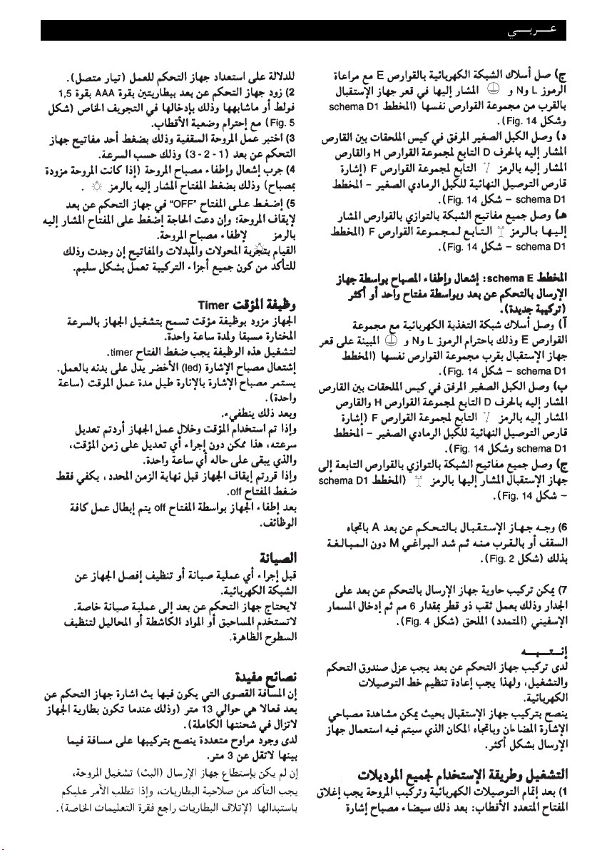
Page 30

INSTALLATION
MODALITES D’INSTALLATION
INSTALLATIONSARTEN
MODALIDADES DE INSTALACIÓN
INSTALLATIE
INSTALLATION
MODALITÀ D’INSTALLAZIONE
2 3
A
C
8 mm. max.
M
B
4 5
Page 31
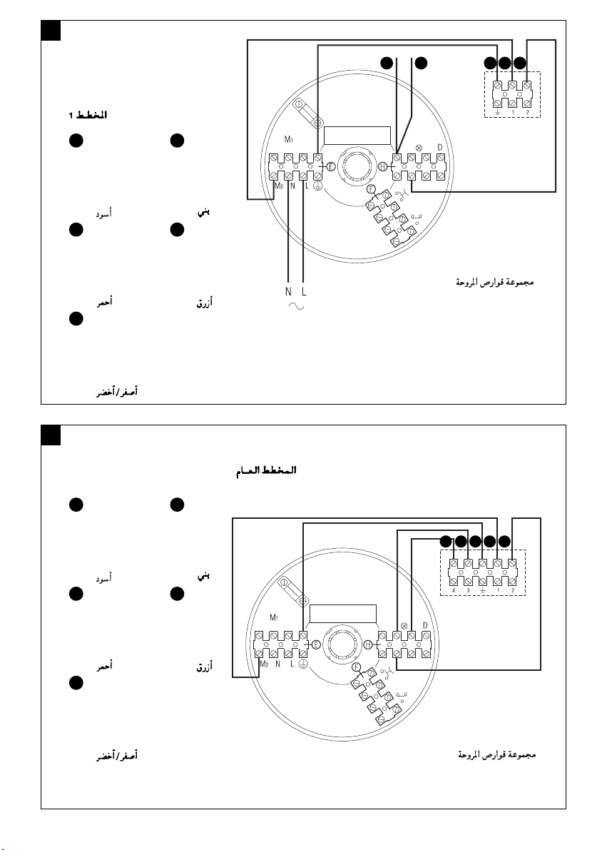
31
Morsetteria ventilatore
Ventilator terminal strip
Bornier ventilateur
Ventilatorklemmenbrett
Regleta del ventilador
Klemmenbord ventilator
Fläktens anslutningsplint
6
SCHEMA 1
DIAGRAM 1
SCHÉMA 1
SCHEMA 1
ESQUEMA 1
SCHEMA 1
KOPPLINGSSCHEMA 1
B
C
A
D
E
A
B
C
D
E
= Nero
Black
Noir
Schwarz
Negro
Zwart
Svart
= Rosso
Red
Rouge
Rot
Rojo
Rood
Röd
= Giallo/Verde
Yellow/Green
Jaune/Vert
Gelb/Grün
Amarillo/Verde
Geel/Groen
Gul/Grön
= Marrone
Brown
Marron
Braun
Marrón
Bruin
Brun
= Blu
Blue
Bleu
Blau
Azul
Blauw
Blå
7
B
C
A
D
E
SCHEMA GENERALE
GENERAL DIAGRAM
SCHÉMA GÉNÉRAL
ALLGEMEINES SCHEMA
Morsetteria ventilatore
Ventilator terminal strip
Bornier ventilateur
Ventilatorklemmenbrett
Regleta del ventilador
Klemmenbord ventilator
Fläktens anslutningsplint
ESQUEMA GENERAL
ALGEMEEN SCHEMA
ALLMÄNT KOPPLINGSSCHEMA
A
B
C
D
E
= Nero
Black
Noir
Schwarz
Negro
Zwart
Svart
= Rosso
Red
Rouge
Rot
Rojo
Rood
Röd
= Giallo/Verde
Yellow/Green
Jaune/Vert
Gelb/Grün
Amarillo/Verde
Geel/Groen
Gul/Grön
= Marrone
Brown
Marron
Braun
Marrón
Bruin
Brun
= Blu
Blue
Bleu
Blau
Azul
Blauw
Blå
Page 32

32
8
SCHEMA A
DIAGRAM A
SCHÉMA A
SCHEMA A
B
CAD
E
ESQUEMA A
SCHEMA A
KOPPLINGSSCHEMA A
Morsetteria ventilatore
Ventilator terminal strip
Bornier ventilateur
Ventilatorklemmenbrett
Regleta del ventilador
Klemmenbord ventilator
Fläktens anslutningsplint
9
SCHEMA B
DIAGRAM B
SCHÉMA B
SCHEMA B
ESQUEMA B
SCHEMA B
KOPPLINGSSCHEMA B
T = Deviatore
Switch
Déviateur
Wechselschalter
Desviador
Omleider
Omkopplare
V= Deviatore
Switch
Déviateur
Wechselschalter
Desviador
Omleider
Omkopplare
W = Lampada esistente nel locale
Lamp existing in the room
Lampe présente dans le local
Im raum vorhandene leuchte
Lámpara ya existente en el local
In de ruimte aanwezige lamp
I lokalen redan befintlig lampa
A
B
C
D
E
= Nero
Black
Noir
Schwarz
Negro
Zwart
Svart
= Rosso
Red
Rouge
Rot
Rojo
Rood
Röd
= Giallo/Verde
Yellow/Green
Jaune/Vert
Gelb/Grün
Amarillo/Verde
Geel/Groen
Gul/Grön
= Marrone
Brown
Marron
Braun
Marrón
Bruin
Brun
= Blu
Blue
Bleu
Blau
Azul
Blauw
Blå
N L
4 W 5
T V
1
2
3
Page 33
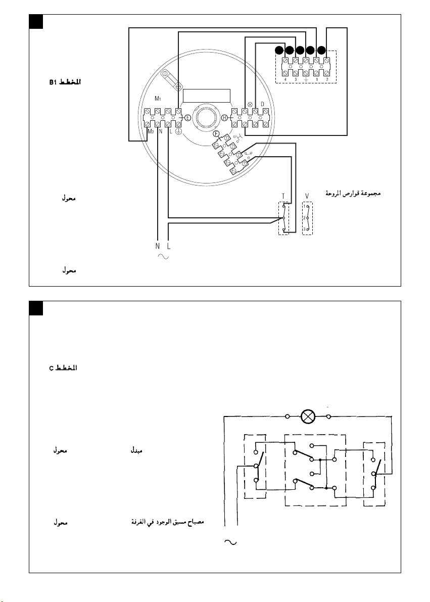
33
10
SCHEMA B1
DIAGRAM B1
SCHÉMA B1
SCHEMA B1
ESQUEMA B1
SCHEMA B1
KOPPLINGSSCHEMA B1
Morsetteria ventilatore
Ventilator terminal strip
Bornier ventilateur
Ventilatorklemmenbrett
Regleta del ventilador
Klemmenbord ventilator
Fläktens anslutningsplint
T = Deviatore
Switch
Déviateur
Wechselschalter
Desviador
Omleider
Omkopplare
V= Deviatore
Switch
Déviateur
Wechselschalter
Desviador
Omleider
Omkopplare
11
SCHEMA C
DIAGRAM C
SCHÉMA C
SCHEMA C
ESQUEMA C
SCHEMA C
KOPPLINGSSCHEMA C
Z = Invertitore
Inverter
Inverseur
Umschalter
Inversor
Inverter
Växelriktare
T = Deviatore
Switch
Déviateur
Wechselschalter
Desviador
Omleider
Omkopplare
V= Deviatore
Switch
Déviateur
Wechselschalter
Desviador
Omleider
Omkopplare
W = Lampada esistente nel locale
Lamp existing in the room
Lampe présente dans le local
Im raum vorhandene leuchte
Lámpara ya existente en el local
In de ruimte aanwezige lamp
I lokalen redan befintlig lampa
B
CAD
E
4 W 5
N L
T
V
Z
1
2
3
Page 34

34
12
SCHEMA C1
DIAGRAM C1
SCHÉMA C1
SCHEMA C1
ESQUEMA C1
SCHEMA C1
KOPPLINGSSCHEMA C1
Morsetteria ventilatore
Ventilator terminal strip
Bornier ventilateur
Ventilatorklemmenbrett
Regleta del ventilador
Klemmenbord ventilator
Fläktens anslutningsplint
T = Deviatore
Switch
Déviateur
Wechselschalter
Desviador
Omleider
Omkopplare
V= Deviatore
Switch
Déviateur
Wechselschalter
Desviador
Omleider
Omkopplare
Z = Invertitore
Inverter
Inverseur
Umschalter
Inversor
Inverter
Växelriktare
13
SCHEMA D
DIAGRAM D
SCHÉMA D
SCHEMA D
ESQUEMA D
SCHEMA D
KOPPLINGSSCHEMA D
P = Pulsante
Button
Bouton
Drucktaste
Interruptor
Drukknop
Tryckknapp
R = Relè
Relay
Relais
Relais
Relé
Relais
Relä
W = Lampada esistente nel locale
Lamp existing in the room
Lampe présente dans le local
Im raum vorhandene leuchte
Lámpara ya existente en el local
In de ruimte aanwezige lamp
I lokalen redan befintlig lampa
B
CAD
E
N L
4 W 5
R
P P P
6
7
8
Page 35

35
14
SCHEMA D1
DIAGRAM D1
SCHÉMA D1
SCHEMA D1
ESQUEMA D1
SCHEMA D1
KOPPLINGSSCHEMA D1
P = Pulsante
Button
Bouton
Drucktaste
Interruptor
Drukknop
Tryckknapp
Morsetteria ventilatore
Ventilator terminal strip
Bornier ventilateur
Ventilatorklemmenbrett
Regleta del ventilador
Klemmenbord ventilator
Fläktens anslutningsplint
A
B
C
D
E
= Nero
Black
Noir
Schwarz
Negro
Zwart
Svart
= Rosso
Red
Rouge
Rot
Rojo
Rood
Röd
= Giallo/Verde
Yellow/Green
Jaune/Vert
Gelb/Grün
Amarillo/Verde
Geel/Groen
Gul/Grön
= Marrone
Brown
Marron
Braun
Marrón
Bruin
Brun
= Blu
Blue
Bleu
Blau
Azul
Blauw
Blå
A
B
C
D
E
B
CAD
E
Page 36

Informazione importante per lo smaltimento ambientalmente compatibile
N
E
Important information concerning the environmentally compatible disposal of the appliance
R
F
Information importante pour l'élimination compatible avec l'environnement
E
D
Wichtige Information für den Benutzer zur umweltfreundlichen Entsorgung des Gerätes
ES
Información importante sobre eliminación respetuosa con el medio ambiente
NL
Belangrijke informatie over milieuvriendelijke afvalverwerking
SV
Viktig information för en miljömässigt förenlig kassering
IT
IN ALCUNI PAESI DELL'UNIONE EUROPEA
QUESTO PRODOTTO NON RICADE NEL CAMPO
DI APPLICAZIONE DELLA LEGGE NAZIONALE DI
RECEPIMENTO DELLA DIRETTIVA RAEE E QUINDI
NON È IN ESSI VIGENTE ALCUN OBBLIGO DI
RACCOLTA DIFFERENZIATA A FINE VITA.
Attenzione
Questo prodotto è conforme alla Direttiva
EU 2002/96/EC.
Il simbolo del cestino barrato riportato
sull’apparecchio indica che il prodotto,
alla fine della propria vita utile, dovendo essere
trattato separatamente dai rifiuti domestici, deve
essere conferito in un centro di raccolta differenziata
per apparecchiature elettriche ed elettroniche oppure
riconsegnato al rivenditore al momento dell’acquisto
di una nuova apparecchiatura equivalente.
L’utente è responsabile del conferimento
dell’apparecchio a fine vita alle appropriate strutture di
raccolta, pena le sanzioni previste dalla vigente
legislazione sui rifiuti.
L’adeguata raccolta differenziata per l’avvio
successivo dell’apparecchio dismesso al riciclaggio, al
trattamento e allo smaltimento ambientalmente
compatibile contribuisce ad evitare possibili effetti
negativi sull’ambiente e sulla salute e favorisce il
riciclo dei materiali di cui è composto il prodotto.
Per informazioni più dettagliate inerenti i sistemi di
raccolta disponibili, rivolgersi al servizio locale di
smaltimento rifiuti, o al negozio in cui è stato
effettuato l’acquisto.
I produttori e gli importatori ottemperano alla loro
responsabilità per il riciclaggio, il trattamento e lo
smaltimento ambientalmente compatibile sia
direttamente sia partecipando ad un sistema collettivo.
EN
IN CERTAIN EUROPEAN UNION COUNTRIESTHIS
PRODUCT DOES NOT FALL WITHIN THE
REQUIREMENTS OF THE NATIONAL LAWS
IMPLEMENTING THE WEEE DIRECTIVE, AND IN
THESE COUNTRIESTHE PRODUCT IS NOT
SUBJECTTO SEPARATE DISPOSAL OPERATIONS
AT THE END OF ITS WORKING LIFE.
36
Important
This product conforms to EU Directive
2002/96/EC.
This appliance bears the symbol of the
barred waste bin.This indicates that, at
the end of its useful life, it must not be disposed of as
domestic waste, but must be taken to a collection
centre for waste electrical and electronic equipment,
or returned to a retailer on purchase of a
replacement.
It is the user's responsibility to dispose of this
appliance through the appropriate channels at the end
of its useful life. Failure to do so may incur the
penalties established by laws governing waste
disposal.
Proper differential collection, and the subsequent
recycling, processing and environmentally compatible
disposal of waste equipment avoids unnecessary
damage to the environment and possible related
health risks, and also promotes recycling of the
materials used in the appliance.
For further information on waste collection and
disposal, contact your local waste disposal service, or
the shop from which you purchased the appliance.
Manufacturers and importers fulfil their responsibilities
for recycling, processing and environmentally
compatible disposal either directly or by participating
in collective systems.
FR
DANS CERTAINS PAYS DE L'UNION
EUROPÉENNE, CE PRODUIT NE FAIT PAS PARTIE
DU DOMAINE D'APPLICATION DE LA LOI
NATIONALE D'ASSIMILATION DE LA DIRECTIVE
DEEE ET PAR CONSÉQUENT, IL N'Y EXISTE
AUCUNE OBLIGATION DE COLLECTE
DIFFÉRENCIÉE À LA FIN DE SA DURÉE DE VIE.
Attention
Ce produit est conforme à la directive EU
2002/96/EC.
Le symbole représentant une poubelle
barrée présent sur l'appareil indique qu'à
la fin de son cycle de vie, il devra être traité séparément
des déchets domestiques.
Il devra donc être confié à un centre de collecte
Page 37

élective pour appareils électriques et électroniques ou
s
apporté au revendeur lors de l'achat d'un nouvel
r
ppareil.
a
L'utilisateur est responsable de la remise de l'appareil
usagé aux structures de collecte compétentes sous
peine des sanctions prévues par la législation sur
l'élimination des déchets.
a collecte sélective réalisée avant le recyclage, le
L
raitement et l'élimination compatible avec l'environnement
t
e l'appareil usagé contribue à éviter les nuisances pour
d
l'environnement et pour la santé et favorise le recyclage
des matériaux qui composent le produit.
Pour de plus amples informations concernant les
systèmes de collecte existants, adressez-vous au
service local d'élimination des déchets ou au magasin
qui vous a vendu l'appareil.
Les fabricants et les importateurs optempèrent à leur
responsabilité en matière de recyclage, de traitement et
d'élimination des déchets compatible avec
l'environnement directement ou par l'intermédiaire d'un
système collectif.
DE
IN EINIGEN EU-LÄNDERN GELTEN FÜR DIESES
PRODUKT NICHT DIE VORGABEN DER
EUROPÄISCHEN RICHTLINIE ÜBER ELEKTROUND ELEKTRONIK-ALTGERÄTE (WEEERICHTLINIE) UND DEMNACH BESTEHT IN
DIESEN LÄNDERN AUCH KEINE PFLICHT FÜR
DIE MÜLLTRENNUNG BEI DER ENTSORGUNG
DES GERÄTES.
Achtung
Dieses Gerät entspricht der EG-Richtlinie
2002/96/EG.
Das Symbol mit der durchgestrichenen
Abfalltonne am Gerät bedeutet, dass das
Gerät nach seiner Aussonderung nicht im
Haushaltsmüll entsorgt werden darf, sondern an einer
Sammelstelle für Elektro- und Elektronikgeräte oder
beim Kauf eines gleichwertigen Neugerätes beim
Händler abzugeben ist.
Der Benutzer hat Sorge zu tragen, dass das Gerät
nach seiner Aussonderung an einer geeigneten
Sammelstelle abgegeben wird. Ein Nichtbeachten
dieser Vorschrift ist gemäß der geltenden
Abfallordnung strafbar.
Das geeignete Sortieren von Abfall und nachfolgende
Recyceln des aussortierten Gerätes zur
umweltverträglichen Entsorgung trägt zum Schutz von
Umwelt und Gesundheit bei und dient der
Wiederverwendung der recyclingfähigen Materialien,
aus denen das Gerät besteht.
Für detailliertere Informationen bezüglich der
verfügbaren Sammelsysteme wenden Sie sich an Ihre
örtliche Behörde oder an den Händler, bei dem Sie
das Gerät gekauft haben.
Die Hersteller und Importeure kommen ihrer
Verpflichtung zum umweltfreundlichen Recycling,
Verarbeiten und Entsorgen sowohl direkt als auch
durch Teilnahme an einem Kollektivsystem nach.
ES
N ALGUNOS PAÍSES DE LA UNIÓN EUROPEA
E
STE PRODUCTO NO ESTÁ INCLUIDO EN EL
E
MBITO DE APLICACIÓN DE LA LEY NACIONAL
Á
QUE TRASPONE LA DIRECTIVA RAEEY, POR LO
TANTO, NO EXISTE OBLIGACIÓN ALGUNA DE
RECOGIDA SELECTIVA AL FINALIZAR SU VIDA
ÚTIL.
Atención
Este producto cumple los requisitos de la
Directiva EU 2002/96/EC.
El símbolo del contenedor de basura
tachado, que hay sobre el aparato, indica que no puede
ser eliminado con los desechos domésticos al finalizar su
vida útil.Se ha de llevar a un punto de recogida selectiva
para aparatos eléctricos o electrónicos o entregar al
proveedor durante la compra de un aparato equivalente.
El usuario deberá llevar el aparato a un punto de
recogida selectiva para su eliminación, de lo contrario
se aplicarán las sanciones previstas por las normas
sobre eliminación de desechos.
La recogida selectiva para la reutilización, tratamiento
y eliminación respetuosa con el medio ambiente del
aparato ayuda a evitar los efectos sobre el medio
ambiente y la salud y favorece el reciclaje de los
materiales que componen el producto.
Para más información sobre los sistemas de
eliminación disponibles, contactar con el servicio local
de eliminación de desechos o con la tienda que
vendió el aparato.
Los fabricantes y los importadores cumplen con su
responsabilidad de recuperación, tratamiento y
eliminación respetuosa con el medio ambiente
directamente o participando a un sistema colectivo.
NL
IN ENKELE LANDEN VAN DE EUROPESE UNIE
VALT DIT PRODUCT NIET ONDER HET
TOEPASSINGSGEBIED VAN DE NATIONALE
WETGEVINGVOOR ERKENNING VAN DE AEEARICHTLIJN EN DERHALVE BESTAAT ER GEEN
ENKELE VERPLICHTING TOT GESCHEIDEN
INZAMELING AAN HET EINDE VAN DE
LEVENSDUUR VAN DIT PRODUCT.
Let op
Dit apparaat is conform de EU Richtlijn
2002/96/EC.
Het symbool op het apparaat met de
afvalbak met een kruis erdoor geeft aan
dat het apparaat, aan het einde van de levensduur,
niet bij het huisvuil gezet mag worden maar
ingeleverd moet worden bij een centrum voor
37
Page 38

escheiden afvalinzameling voor elektrische en
g
lektronische apparaten of teruggegeven moet
e
orden aan de winkel op het moment van de
w
aanschaf van een gelijkwaardig nieuw apparaat.
De gebruiker is verantwoordelijk voor het inleveren
van het apparaat bij een daarvoor geschikt
inzamelingspunt, op straffe van sancties op basis
van de heersende wetgeving inzake afvalverwerking.
De adequate gescheiden inzameling ten einde het
ingeleverde apparaat te kunnen recyclen,
behandelen en milieuvriendelijk tot afval te kunnen
verwerken draagt bij aan het voorkomen van
mogelijk negatieve invloeden op het milieu en de
gezondheid en bevordert de recycling van
materialen waaruit het apparaat is samengesteld.
Voor nadere informatie over de beschikbare
afvalverwerkingssystemen kunt u contact opnemen
met de plaatselijke afvalverwerkingsdienst, of bij de
winkel waar u het apparaat heeft aangeschaft.
De fabrikanten en importeurs zijn verantwoordelijk
voor de recycling, de behandeling en de
milieuvriendelijke afvalverwerking zowel direct als
door deelname aan een collectief systeem.
SV
I VISSA LÄNDER I EUROPAUNIONEN FALLER
INTE DENNA PRODUKT UNDER DEN
NATIONELLA LAGSTIFTNINGEN SOM
INTEGRERAR DIREKTIVET OM AVFALL SOM
UTGÖRS AV ELLER INNEHÅLLER ELEKTRISKA
ELLER ELEKTRONISKA PRODUKTER.
SÅLUNDA FINNS DET INTE I DESSA LÄNDER
NÅGOT KRAV PÅ SEPARAT INSAMLING VAD
GÄLLER DENNA PRODUKT.
insamlingssystemen, vänd dig till den lokala
återvinningsstationen, eller till affären där du gjort
inköpet.
illverkarna och importörerna tar sitt ansvar för
T
tervinningen, hanteringen och den miljömässigt
å
förenliga kasseringen såväl direkt som genom att
delta i ett kollektivt system.
Varning
Denna produkt överensstämmer med
EU 2002/96/EC direktivet.
Symbolen med det korsade kärlet
applicerad på produkten anger att produkten, när
den tjänat ut sitt syfte, eftersom den måste hanteras
separat från hushållsavfall, måste lämnas in till en
miljöstation för elektriska och elektroniska apparater
eller återlämnas till återförsäljaren vid inköp av en
likvärdig apparat.
Användaren är ansvarig för inlämningen av
apparaten, när den tjänat ut sitt syfte, till de avsedda
insamlingsstrukturena, i annat fall kan straff enligt
gällande lagstiftning för avfallshantering bli följden.
Den anpassade differentierade insamlingen för den
därpå följande återvinningen, hanteringen och
miljömässigt förenliga kasseringen av den avlagda
apparaten bidrar till att undvika möjliga negativa
effekter på miljön och för hälsan och underlättar
återvinningen av materialen av vilken produkten är
tillverkad.
För mer detaljerad information rörande de tillgängliga
38
Page 39

Warning: this symbol indicates precautions that must be taken to avoid injury
• Certain fundamental rules must be observed when using any electrical appliance, including:
never touch electrical appliances with wet or damp hands;
-
- never touch appliances while barefoot;
- never allow children or infirm persons to operate appliances unattended
This appliance is not suitable for use by children or by individuals with reduced physical, sensorial or mental capacities, or by
•
nexperienced or untrained individuals, unless they are supervised or instructed in its use by a person responsible for their safety
i
Children must always be supervised to ensure that they do not play with the appliance.
Attention : ce symbole indique la nécessité de prendre quelques précautions pour la
sécurité de l’utilisateur
• L'utilisation de tout appareil électrique implique le respect de quelques règles fondamentales dont, entre autres :
- ne pas toucher l'appareil avec des mains mouillées ou humides;
- ne pas toucher l'appareil pieds nus;
- interdire son utilisation aux enfants ou aux personnes inexpertes.
• Cet appareil n'est pas approprié à l'emploi de la part de personnes (y compris les enfants) avec des capacités physiques,
sensorielles ou mentales réduites ou sans expérience ni connaissance, à moins qu'elles ne soient surveillées ou qu'elles n'aient
été instruites au sujet de l'emploi de l'appareil par une personne responsable de leur sécurité. Les enfants doivent être surveillés
pour s'assurer qu'ils ne jouent pas avec l'appareil.
Achtung:dieses Symbol zeigt Vorsichtsmaßnahmen zum Schutz des Benutzers an
• Beim Gebrauch von Elektrogeräten jeder Art müssen stets einige Grundregeln beachtet werden, darunter im Einzelnen:
- die Geräte niemals mit nassen oder feuchten Händen berühren;
- die Geräte niemals barfuß berühren;
- die Geräte dürfen nicht durch Kinder oder unzurechnungsfähige Personen benutzt werden.
• Dieses Gerät darf von Kindern oder Personen mit eingeschränkten körperlichen oder geistigen Fähigkeiten oder mangelnder
Erfahrung bzw. Kenntnis nur unter der Aufsicht oder nach gründlicher Unterweisung und Überprüfung seitens einer für ihre
Sicherheit verantwortlichen Person bedient werden. Kinder sind zu überwachen, damit sie nicht mit dem Gerät spielen.
Atención:este símbolo indica precauciones para evitar daños al usuario.
•
Cuando se utiliza un aparato eléctrico es necesario tener en cuenta algunas normas básicas:
- no tocar el aparato con las manos mojadas o húmedas;
- no tocar el aparato con los pies descalzos;
- no permitir que los niños o las personas con discapacidad lo utilicen
• Este aparato no es apto para ser utilizado por niños ni personas con discapacidad física, sensorial o psíquica, o que carezcan
de la experiencia y los conocimientos necesarios, excepto cuando lo hagan bajo la supervisión de una persona responsable
de su seguridad o que les haya instruido en el manejo.
39
Page 40

Let op: dit symbool markeert voorzorgsmaatregelen ter voorkoming van risico’s voor de
La Vortice S.p.A. si riserva di apportare tutte le varianti migliorative ai prodotti in corso di vendita.
Vortice S.p.A. reserves the right to make improvements to products at any time and without prior notice.
La société Vortice S.p.A. se réserve le droit d'apporter toutes les variations afin d'améliorer ses produits en cours de commercialisation.
Die Firma Vortice S.p.A.behält sich vor, alle eventuellen Verbesserungsänderungen an den Produkten des Verkaufsangebots vorzunehmen
Vortice S.p.A. se reserva el derecho de incorporar todas las mejoras necesarias a los productos en fase de venta.
Vortice S.p.A. behoudt zich het recht voor aan de modellen uit haar catalogi alle verbeteringen aan te brengen die zij wenselijk acht.
Vortice S.p.A. förbehåller sig rätten att göra förbättrande förändringar på produkterna som är till försäljning.
gebruiker
• Bij het gebruik van elektrische apparaten moeten enige basisregels in acht genomen worden en wel:
- raak het apparaat niet aan met vochtige of natte handen;
raak het apparaat nooit aan als u op blote voeten loopt;
-
- zorg ervoor dat het apparaat niet wordt gebruikt door kinderen of ondeskundigen.
• Dit apparaat is niet geschikt voor gebruik door personen (waaronder kinderen) met verminderde fysieke, zintuiglijke of mentale
vermogens, of die geen ervaring en kennis hebben van het apparaat, tenzij ze onder toezicht staan van of geïnstrueerd zijn
m.b.t. het gebruik van het apparaat door een persoon die verantwoordelijk is voor hun veiligheid. Kinderen moeten onder
oezicht blijven om ervoor te zorgen dat ze niet met het apparaat spelen.
t
Varning: denna symbol anger försiktighetsåtgärder som ska vidtas för att undvika att
användaren utsätts för skador
•
Vid användning av elektriska apparater måste vissa grundläggande regler följas, bland annat:
- Vidrör inte apparaten med våta eller fuktiga händer.
- Använd inte apparaten om du är barfota.
- Låt inte barn eller personer utan lämplig kompetens använda apparaten
• Denna apparat får inte användas av personer (inklusive barn) med nedsatta fysiska, sensoriska eller mentala förmågor, eller
av personer utan erfarenhet och kunskap, om inte de är övervakade eller instruerade om användningen av apparaten av
personeransvariga för deras säkerhet. Barn ska övervakas för att säkerställa att de inte leker med apparaten.
 Loading...