

Vortice NRG EC 600, NRG EC 800, NRG EC 2500, NRG EC EH 600, NRG EC 1500 Operating And Commissioning Instructions
...Page 1
Manuale di uso e attivazione
Operating and commissioning instructions
Manuel d’utilisation et de mise en marche
VORT NRG EC / EC EH
600 - 800 - 1500 - 2000 - 2500
COD. 5.471.084.301
VORTICE LIMITED
Beeches House - Eastern Avenue
Burton on Trent
DE13 0BB
Tel. (+44) 1283-492949
Fax (+44) 1283-544121
UNITED KINGDOM
VORTICE FRANCE
15-33, Rue Le Corbusier Europarc
CS 30007
90046 CRETEIL CEDEX
FRANCE
15/02/2016
VORTICE ELETTROSOCIALI S.p.A.
Strada Cerca, 2 - frazione di Zoate
20067 TRIBIANO (MI)
Tel. (+39) 02-90.69.91
Fax (+39) 02-90.64.625
ITALIA
Page 2

Prima di usare il prodotto leggere attentamente
le istruzioni contenute nel presente libretto.
ortice non potrà essere ritenuta responsabile
V
per eventuali danni a persone o cose causati
dal mancato rispetto delle indicazioni di seguito
elencate, la cui osservanza assicurerà invece la
durata e l’affidabilità, elettrica e meccanica,
ell’apparecchio.
d
Conservare sempre questo libretto istruzioni.
Before installing and using your product, read these
instructions carefully. Vortice will not accept any
responsibility for damage to property or personal
harm resulting from failure to abide by conditions
given in this booklet.
Following these instructions will ensure long service
life and overall electrical and mechanical reliability.
Keep this instruction booklet in a safe place for
reference purposes.
Vor der Benutzung des Gerätes muss die vorliegende
Anleitung aufmerksam durchgelesen werden.
Vortice haftet nicht für Personen- und/oder
Sachschäden, die auf die Nichtbeachtung der in
diesem Handbuch enthaltenen und für einen
korrekten Betrieb, die mechanische und
elektrische Sicherheit sowie eine lange Lebensdauer
des Gerätes wichtigen Hinweise bzw. Anleitungen
zurückzuführen sind.
Bewahren Sie diese Betriebsanleitung
gewissenhaft auf.
Avant d’utiliser l’appareil, lire attentivement les
instructions données dans cette notice.
La société Vortice ne pourra être tenue pour
responsable des dommages causés aux personnes
ou aux biens si les consignes ci-dessous ne sont
pas respectées car elles garantissent la durée de vie
et la fiabilité électrique et mécanique de l’appareil.
Toujours conserver ce livret d’instructions.
Prije korištenja proizvoda, pažljivo pročitajte upute koje
sadrži ovaj priručnik.
Tvrtka Vortice se ne može smatrati odgovornom za
eventualnu štetu nanesenu osobama ili stvarima uslijed
nepoštivanja uputa koje se u nastavku navode, a
pridržavanjem kojih se osigurava trajnost te električna i
mehanička pouzdanost uređaja.
Brižljivo čuvajte ove upute za uporabu.
Před použitím výrobku si pozorně přečtěte pokyny
obsažené v této příručce.
Podnik Vortice neodpovídá za případná zranění osob nebo
poškození věcí způsobené nedodržením dále uvedených
pokynů; jejich dodržování naopak zajistí dlouhodobou
životnost výrobku, jak elektrickou, tak i mechanickou.
Tento návod kobsluze si proto uschovejte.
2
Pred používaním spotrebiča si pozorne prečítajte všetky
pokyny v tomto návode.
Vortice nebude zodpovedať za žiadne poranenia osôb ani
škody na majetku spôsobené nedodržaním upozornení
uvedených v nasledujúcom texte, ktorých dodržiavanie,
naopak, zaručí dlhodobú elektrickú a mechanickú
spoľahlivosť, spotrebiča.
Tento návod na používanie si starostlivo odložte.
Page 3

ENGLISH
I RECEIVING THE EQUIPMENT ................................................................................................................52
I.1 Checks on receipt ...................................................................................................................................52
I.2 Unpacking................................................................................................................................................52
I.3 Storage ....................................................................................................................................................52
II INSTALLATION........................................................................................................................................52
II.1 Handling..................................................................................................................................................52
II.2 Space required .......................................................................................................................................53
II.3 Positioning ..............................................................................................................................................54
III GENERAL OPERATION .........................................................................................................................54
III.1 General ..................................................................................................................................................54
III.2 OPERATING SEQUENCE ......................................................................................................................54
III.3 CONTROL MODES................................................................................................................................55
III.3.a. VORT NRG EC .......................................................................................................................................55
III.3.b. ECO:......................................................................................................................................................55
III.3.c. DIVA........................................................................................................................................................55
III.3.d. LOBBY® ................................................................................................................................................55
III.4. COMPOSITION ......................................................................................................................................56
III.5.b. SEASON CONTROL ..............................................................................................................................57
III.5. POSITIONING OF THE CONTROL PANEL ELEMENTS........................................................................57
III.5.a. ECO/DIVA/LOBBY CONTROL ...............................................................................................................57
IV.3. CONNECTION OF TEMPERATURE SENSORS....................................................................................58
IV.2. VORT NRG EC DIAGRAM ....................................................................................................................58
IV. ELECTRICAL WIRING...........................................................................................................................58
IV.1. ELECTRICAL POWER SUPPLY............................................................................................................58
VI.4 CONNECTION TERMINALS - VORT NRG EC FIRST/DIVA/LOBBY.....................................................59
IV.5. Electrical connection and operation of the plate heat exchanger.........................................................60
IV.5.a. VORT NRG EC version ...........................................................................................................................60
IV.5.b. FIRST PREMIUM INFINITE AND SMART version..................................................................................60
IV.6. Auto defrost ...........................................................................................................................................61
IV.6.a. VORT NRG EC version ...........................................................................................................................61
IV.6.b. FIRST PREMIUM INFINITE and VORT NRG EC EH version..................................................................61
IV.7. Connection of the filter pressure switches ............................................................................................61
IV.8. Connection of the fan pressure switches..............................................................................................61
IV.9. Connection of pressure senders for LOBBY® ......................................................................................62
IV.10. Connection of motors ..........................................................................................................................62
IV.11. CO2 sender connection.......................................................................................................................62
IV.12. Night Cooling .......................................................................................................................................63
IV.13. Changeover coil...................................................................................................................................63
IV.14. Direct expansion coil for cooling only or reversible coil......................................................................64
IV.15. Electric heater battery..........................................................................................................................64
IV.16. Defrost heater battery..........................................................................................................................65
IV.17. Fire protection function........................................................................................................................65
IV.18. Dehumidification function ....................................................................................................................65
IV.19. MODBUS/WEB/BACNET connection..................................................................................................66
IV.20. Repeater connection............................................................................................................................66
IV.21. LON ......................................................................................................................................................67
49
Page 4

ENGLISH
V. PARAMETER DEFINITION ......................................................................................................................67
V.1. Control (integral or remote control).........................................................................................................67
V.2. Example parameter settings...................................................................................................................68
V.3. Standard settings (operator menu) .........................................................................................................68
V.3.a. Operation Mode menu ............................................................................................................................69
V.3.c. Ventilation control menu..........................................................................................................................70
V.3.b. Temperature control menu ......................................................................................................................70
V.3.d. Timer setting menu .................................................................................................................................71
V.4. Modification of operator parameters (password 3333 required)............................................................72
V.4.a. Setting different time and date clocks ....................................................................................................72
V.4.a.1. Date and time o the CORRIGO controller[(1) section V.3.d]...................................................................72
V.4.a.2. Programming system operation times [(2) (3) chapter V.3.d]..................................................................72
V.4.a.3. Vacation period [(4) section V.3.d] (password 3333 required).................................................................72
V.4.b. Modifying the speed/pressure for LS and HS operation........................................................................72
V.4.b.1. STANDARD (ECO)/DIVA [(5) section V.3.c]............................................................................................72
V.4.b.2. LOBBY [(5) section V.3.c]........................................................................................................................72
V.4.c. Modifying the temperature setpoint........................................................................................................73
V.4.d. Forced shutdown of control panel or forced LS or HS run of remote control .......................................73
V.4.e. Language selection .................................................................................................................................73
V.5. Intermediate settings (function level) ......................................................................................................73
V.5.a. Configuration menu with function level access ......................................................................................73
V.5.b. Modification of function parameters (password 2222 required).............................................................74
V.5.b.1. System control mode ...............................................................................................................................74
V.5.b.2. Ventilation parameters.............................................................................................................................74
V.5.b.3. CO2 setpoint for DIVA QUATTRO option ................................................................................................74
V.6. Administrator settings.............................................................................................................................74
V.6.a. Configuration menu with admin level access .........................................................................................75
V.7. Modification of function parameters.......................................................................................................75
V.7.a. MODBUS.................................................................................................................................................75
V.7.a.1. Repeaters and EXO communication .......................................................................................................76
V.7.a.2. WEB communication ...............................................................................................................................76
V.8.a.3. BACNET IP communication with BASC type ..........................................................................................76
V.8.a.4. LON communication (if CORRIGO with LON option)..............................................................................77
V.8.a.5. Activation of fire protection function.........................................................................................................77
V.8.a.6. Activation of the dehumidification function ..............................................................................................77
VI. PROBLEM SOLVING.............................................................................................................................78
VI.1. Different types of fault ...........................................................................................................................78
VI.2. Alarms list ..............................................................................................................................................79
VI.3. Cancelling the “Servicing required” alarm ............................................................................................80
VII. MAINTENANCE ....................................................................................................................................81
VII.1. Essential maintenance..........................................................................................................................81
VII.2. Battery replacement .............................................................................................................................81
VIII. APPENDICES .....................................................................................................................................82
VIII.1. Control diagram ...................................................................................................................................82
VIII.2. Connection of motors for VORT NRG EC / EC EH 600 - 800 ............................................................83
VIII.3. Connection of motors for VORT NRG EC / EC EH 1500-2000-2500 .................................................84
VORT NRG EC / EC EH 1500........................................................................................................................85
VORT NRG EC / EC EH 800..........................................................................................................................85
VORT NRG EC / EC EH 600..........................................................................................................................85
50
Page 5

ENGLISH
III.4. Curves..................................................................................................................................................85
V
VORT NRG EC / EC EH 2500........................................................................................................................86
ORT NRG EC / EC EH 1800........................................................................................................................86
V
VIII.5. MODBUS and BACNET table..............................................................................................................87
VIII.5.a. MODBUS information ..........................................................................................................................87
VIII.5.b. BACNET description............................................................................................................................89
VIII.5.c. TABLE...................................................................................................................................................91
INPUT REGISTER................................................................................................................................................91
HOLDING REGISTER ..........................................................................................................................................92
IX. NOTES...................................................................................................................................................94
INPUT STATUT REGISTER .................................................................................................................................94
51
Page 6

ENGLISH
SAFETY INSTRUCTIONS
In compliance with the current standards, the machine should be installed only by technical personnel who are
qualified to work on equipment of this type.
Use the required personal protection equipment to avoid risk of injury from electrical, mechanical (injury from contact
ith steel sheets, sharp edges, etc.) eye protection (UVC hazard; wear goggles to EN170) or noise hazards.
w
Do not use this equipment for any purpose other than that for which it is designed. This machine may be used
exclusively for the distribution of air that is free of hazardous substances.
he machine should be handled in accordance with the indications given in the relative section of this manual.
T
The machine must be connected to earth in accordance with the applicable regulations. Never start a unit that has
not been connected to earth.
Before carrying out any work on a unit, make sure that its is switched off and before opening panels or doors, wait
until all the moving parts have come to a stop (damper, fan and rotary heat exchanger).
During operation, all panels, inspection hatched and doors must always be fitted and closed.
The unit must only be started or stopped using the proximity switch.
Safety and control devices must not be removed, by-passed or deactivated.
When working on the unit, be aware that certain components can reach high temperatures (water coil or electric
heater).
The system must be installed in accordance with fire prevention regulations.
All waste materials must be disposed of in accordance with the applicable regulations.
The manufacturer accepts no liability for damages ensuing from the incorrect use of the equipment, unauthorized
repair or modification, or failure to follow the instructions given in this manual.
I RECEIVING THE EQUIPMENT
Systems are supplied fixed to guides or plates and wrapped in plastic film.
I.1 Checks on receipt
On receipt of the equipment, carefully inspect the packaging and the contents. If damaged, record an accurate
description of the damage on the delivery note.
I.2 Unpacking
When unpacking the equipment, check the following:
- The total number of packages is present.
- All the accessories (dampers, covers, electrical equipment. etc.) ordered are present.
After unpacking the equipment, all packaging materials should be disposed of in accordance with the applicable
regulations.
Dispose of waste materials responsibly.
I.3 Storage
The equipment must be stored in a dry enclosed area, at a temperature between -20 and 40°C; note that the packaging
does not offer sufficient protection against bad weather.
II INSTALLATION
II.1 Handling
The units must only be moved to their installation position.
If the equipment is handled using a fork-lift truck, ensure the forks support the load-bearing structure. Check that the load
capacity of the handling equipment used is suitable for the weight of the equipment received (refer to the weight data in
the manual).
If the equipment is handled using a crane, use 4 lifting ropes of the length indicated. The ropes must be at least as long
as the greatest distance between two attachment points.
_
If the length + width + height > 5 metres
the packing crate must lifted using a sling bar.
52
Page 7
ENGLISH
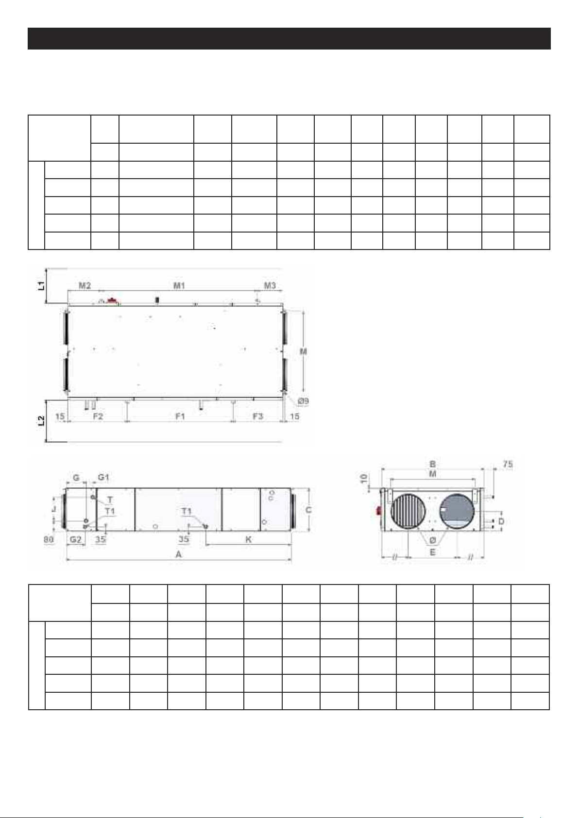
II.2 Space required
Generally there should be a free space of at least half the width of casing at each side to allow access for maintenance.
hese units require a siphon and therefore must be installed at a sufficient height to allow this to be installed.
T
dimensions
600 400 490 225 470 - - - - - - 135
00
8
1500 520 850 380 670 1170 510 510 795 735 660 275
2000 520 430 435 670 1115 580 580 915 725 635 295
NRG EC / EC EH
2500 690 430 435 1020 1235 580 580 840 785 770 405
L1
mm mm mm mm mm mm mm mm mm mm kg
00640
4
L2
Heat exchangerL2Fan
20
3
L2
CO coil
60
5
M1 M2 M3 F1 F2 F3
- - - - - - 2
Weigh
ts
00
dimensions
600 250 1700 780 330 160 370 150 50 145 170 170 645
800 315 2020 965 415 210 460 150 50 145 250 250 780
1500 355 2190 1220 415 190 600 430 50 425 250 250 880
2000 400 2275 1220 495 245 600 430 50 425 330 330 885
NRG EC / EC EH
2500 400 2395 1740 495 235 910 430 50 425 330 330 985
mm mm mm mm mm mm mm mm mm mm mm mm
A B C D E G G1 G2 J K M
53
Page 8

ENGLISH
II.3 Positioning
The system must be suspended above or supported on a sufficiently rigid surface (use a vibration damping mounts if
ecessary). For ductwork connections, select duct sections to suit the dimensions of the flexible hoses, which should be
n
properly tensioned. The ducts should be insulated and the first accessories should be installed at a distance of 2.5 times
the duct diameter from the unit (T junction, etc.). Install the unit in such a way that internal components cannot be
damaged by bad weather or ambient temperature either during the installation or subsequent use of the unit.
Install a siphon on each condensate drain pipe.
condensate drain pipe. Caution: the siphons must be connected in the correct manner in order to
nsure that the condensate can drain freely.
e
The value H must correspond (in mm) to at least the maximum internal negative pressure of the
system x 1.
Example: Dp = 500 Pa = 50 mm CE
_
H > 50 mm 2H > 100 mm
Installation of systems in ceilings: units can be suspended on threaded rods. They can also be supported on a frames
attached to the structure of the building, provided that the frames have sufficient load capacity (frames to supplied by the
installer).
A siphon must not be used for more than one
III GENERAL OPERATION
III.1 GENERAL
The VORT NRG EC EC/EH 600-2500 range consists of a programme of dual-flow systems with self-regulating energy
recovery, with high efficiency and high performance, designed for the service sectors and industrial installations.
Performance exceeds 90%.
VORT NRG EC: Management of fans by potentiometer and bypass. Cannot be used with coils.
VORT NRG EC FIRST: Econological management of fans and the bypass. Allows management of a non-integrated coil
changeover (or a hot water coil and/or a cold water coil non-integrated) or an electrical non-integrated heater battery. On
request, it can be adapted for use with a non-integrated electrical heater battery and a non-integrated cold water coil.
VORT NRG EC PREMIUM BC: Econological management of fans and the bypass. Integral changeover coil.
VORT NRG EC PREMIUM BE: Econological management of fans and the bypass. Integral electrical heater battery and
provision for the addition of an extra non-integrated cold water coil.
VORT NRG EC INFINITE BC: Econological management of fans and the bypass. Integral changeover coil and integral
defrost coil.
VORT NRG EC INFINITE BE: Econological management of fans and the bypass. Integral electrical heater battery and
integral defrost coil and provision for the addition of an extra non-integrated cold water coil.
VORT NRG EC EH: Econological management of fans and the bypass. Integral defrost heater battery and provision for
the addition of one non-integrated changeover coil or (one non-integrated hot water and/or one non-integrated cold water
coil).
III.2 OPERATING SEQUENCE
Except VORT ENERGY EC versions
Start-up sequence:
• The recovery fan or VAR pressure monitoring mode starts at the same moment the fresh air damper is operated.
• The blower fan or VAR pressure monitoring mode starts at the same moment the recovery air damper is operated.
• Temperature control starts in accordance with the configured control mode. Electrical heating (if configured) starts on
the flow controller only (flow reversal). Pumps that have not yet been activated will start up.
• The alarm management function is activated after the pre-set time period. At this point the system is operating in
normal mode.
Conditions for startup:
The system starts up when one of the following conditions is met:
• The programmed schedule (timer) for normal speed or low speed operation is on “Run”.
• The system is started manually from the CORRIGO controller.
• One of the digital inputs for forced run is activated.
54
Page 9

ENGLISH
!
Shutdown sequence:
The system shutdown procedure is as follows:
• Deactivation of the alarm management function.
• Deactivation of electrical heating (if configured).
After a certain time interval (individually pre-set for each fan), the fans are switched off.
•
• The fresh air and return air dampers are closed.
• The signals sent to the actuators are re-set to zero and the pumps are stopped.
Conditions for shutdown:
The system shuts down when one of the following conditions is met:
• The programmed schedule (timer) for normal speed or low speed operation is on “Stop” and the forced run signal is
also on “Stop”.
• Activation of the external shutdown command.
• The system is shut down manually from the CORRIGO controller.
• Intervention of an alarm configured with the supplementary shutdown function. The system will restart automatically
once the alarm has been reset.
III.3 CONTROL MODES
III.3.a. VORT NRG EC
1 speed that can be controlled by potentiometer
Each fan can be controlled individually by a potentiometer integrated in the system.
Possibility to add a remote forced shutdown control connected in series to the contactor (not supplied).
III.3.b. ECO:
1 or 2 speeds that can be controlled via the display/remote control/external control “VENTIL. MODE (%)”
Setting of a minimum speed (LS - 1/2) and a maximum speed (HS - 1/1 as %.
Pa
GV Speed
Equipped with factory-set timer:
• (HS - 1/1) from 06:00 to 22:00
• (LS - 1/2) from 22:00 to 06:00
PV Speed
Possibility to add a remote forced run control (LS - 1/2) or (HS - 1/1)
Possibility to add a remote forced shutdown control
III.3.c. DIVA
Proportional ventilation between two flow rates (HS/LS) with “AUTOMATIC CO2CONTROL MODE”.
Setting of a minimum speed (LS - 1/2) and a maximum speed (HS - 1/1) as %.
The CO2setpoint is factory-set to 1000 ppm (in accordance with RT2012).
The transition between (LS - 1/2) and (HS - 1/1) is controlled in accordance with the CO
level.
Equipped with continuous run factory-set timer (LS - 1/2).
Possibility to add a remote forced run control (LS - 1/2) or (HS - 1/1) (NO volt-free contacts)
Possibility to add a remote forced shutdown control (NO volt-free contacts)
Note: In order for the CO2 control to function correctly, the system must meet the following conditions:
• Timer (HS - 1/1) on 0 (inactive) (Normal speed timer)
• Timer (LS - 1/2) in operation (Low speed timer)
• Forced run (HS - 1/1) and Forced shutdown not activated.
Pa
2
PV flow rate
GV Speed
PV Speed
flow rate
flow rate
III.3.d. LOBBY
®
Constant ventilation pressure. (Pa) “CONSTANT Pa MODE”
Setting a constant pressure (Pa).
Equipped with continuous running factory-set timer (LS - 1/2);
Possibility to add a remote forced run control (LS - 1/2)
Possibility to add a remote forced shutdown control
Pa
Constant pressure
flow rate
55
Page 10
ENGLISH
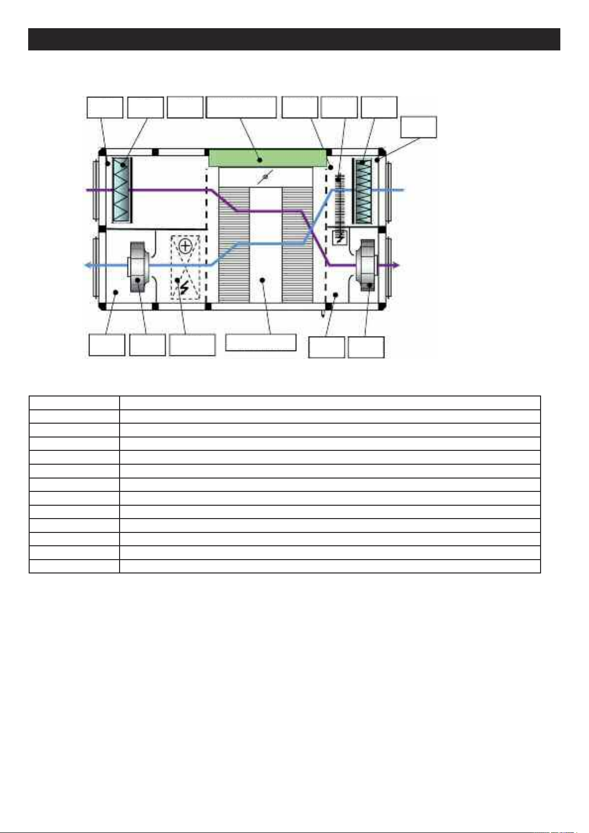
III.4. COMPOSITION
SRG
SSG VS
FR SM
CO/BE
CONTROLS
HEAT EXCHANGER
The sensor group is not integrated in the SEASON version
SBD DBE
SDG
FS
SEG
VR
NAME Description
VS Blower fan
VR Recovery fan
SSG Recovery air pressure switch or recovery air pressure sender for LOBBY version
SDG 230/24 V power transformer
SEG Duct recovery sensor
SRG CO2sensor (DIVA version only)
SDB Lockable proximity switch
FS Supply filter
FR Recovery filter
SM 100% bypass servomotor
CO/BE Changeover heater battery or electric heater battery (depending on version)
DBE Defrost heater battery for INFINITE model only
56
Page 11

ENGLISH
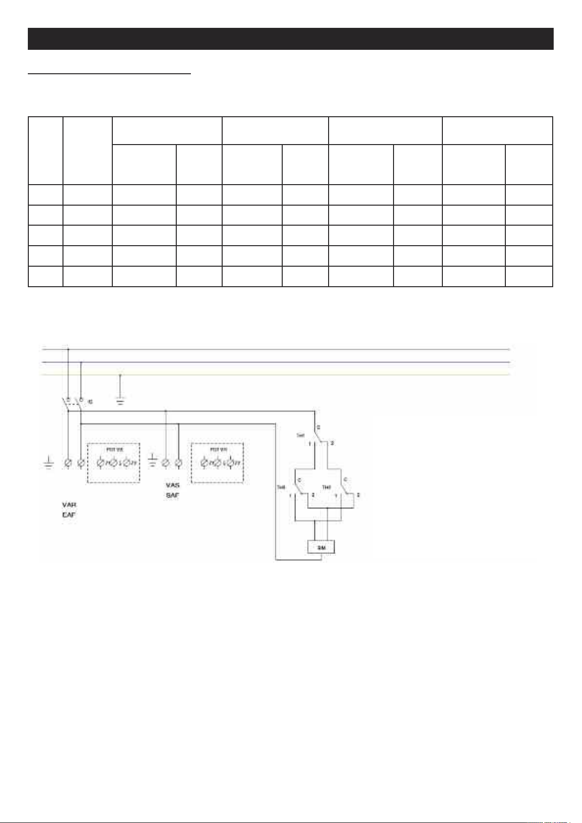
II.5. POSITIONING OF THE CONTROL PANEL ELEMENTS
I
III.5.a. ECO/DIVA/LOBBY CONTROL
N° NAME Description
1 DEPFS Supply filter pressure switch
2 DEPS or TRPS Supply pressure switch or supply pressure sender for LOBBY version
3 DEPR or TRPR Recovery air pressure switch or recovery air pressure sender for LOBBY version
4 TRAFO 230/24 V power transformer
5 SRG Duct recovery sensor
6 CO2 CO2sensor (DIVA version only)
7 IPC Lockable proximity switch
8 K1 Electrical heating coil contactor
9 KD Contactor for the electric defrost heater battery
10 CONTROLLER CORRIGO E283W3 Controller
11 TERMINAL BOARD Control terminal board
12 THA/THS/THSD The overheating and antifreeze thermostats are integrated in the panel
III.5.b. SEASON CONTROL
N° NAME Description
1 DEPFS Supply filter pressure switch
2 DEPS Supply pressure switch
3 DEPR Recovery pressure switch
4 IPC Lockable proximity switch
5 THD Defrost thermostat (+5°C)
6 TERMINAL BOARD Connection terminals
7 TH2 Summer setpoint thermostat for bypass closure
8 TH1 Winter setpoint thermostat for bypass closure
57
Page 12
ENGLISH
IV. ELECTRICAL WIRING
IV.1. ELECTRICAL POWER SUPPLY
Electric
motor
Model
600 2 x 169W 230 / 1 / 50 2.8 230 / 1 / 50 8.2 230 / 1 / 50 8.2 230 / 1 / 50 13.7
800 2 x 220W 230 / 1 / 50 3.4 230 / 1 / 50 14.3 230 / 1 / 50 11.0 230 / 1 / 50 21.9
1500 2 x 400W 230 / 1 / 50 8.6 230 / 1 / 50 23.8 230 / 1 / 50 19.5 230 / 1 / 50 34.7
2000 2 x 400W 230 / 1 / 50 8.6 230 / 1 / 50 24.9 230 / 1 / 50 24.9 400 / 3+N / 50 15.1
2500 2 x 400W 230 / 1 / 50 8.6 230 / 1 / 50 31.4 230 / 1 / 50 31.4 400 / 3+N / 50 19.5
power
rating
(W)
VORT NRG EC
FIRST & PREMIUM BC
ower supply
P
voltage
(V / Ph / Hz)
rotection
P
rating
(A)
INFINITE CO
& VORT NRG EC EH
ower supply
P
voltage
(V/Ph/Hz)
P
rotection
rating
(A)
PREMIUM BE INFINITE BE
ower supply
P
voltage
(V/Ph/Hz)
rotection
P
rating
(A)
ower supply
P
voltage
(V/Ph/Hz)
P
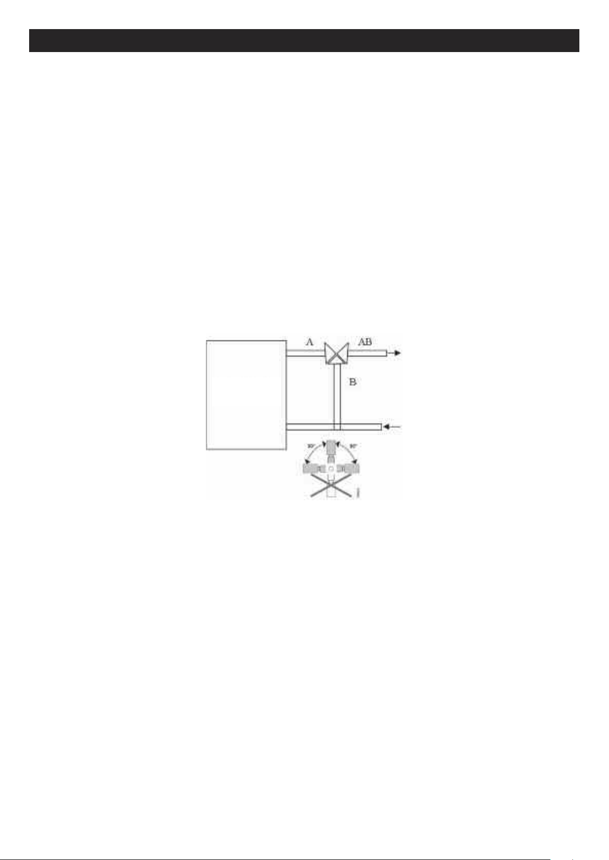
IV.2. VORT NRG EC DIAGRAM
rotection
rating
(A)
TH1= External temperature for heat recovery via
heat exchanger (factory setting: 18°C)
TH2= External temperature for cold recovery via
heat exchanger (factory setting: 24°C)
TH3= Temperature of emission for defrost via
bypass (factory setting: 5°C) -> Do not change this
setting
IV.3. CONNECTION OF TEMPERATURE SENSORS
Except VORT NRG EC version
The temperature sensors are connected directly to the controller
• SSG : Duct supply sensor connected to Agnd(30) and AI1(31)
• SEG : Duct external sensor connected to Agnd(30) and AI1(32)
• SDG : Duct defrost sensor connected to Agnd(33) and AI1(34)
• SRG : Duct recovery sensor connected to Agnd(33) and AI1(35)
• SBD : Defrost heater battery sensor connected to Agnd(36) and AI4(37) on SMART and INFINITE versions (replaced
by 1030 Ohm resistance on other versions)
58
Page 13
ENGLISH
VI.4 CONNECTION TERMINALS - VORT NRG EC FIRST/DIVA/LOBBY
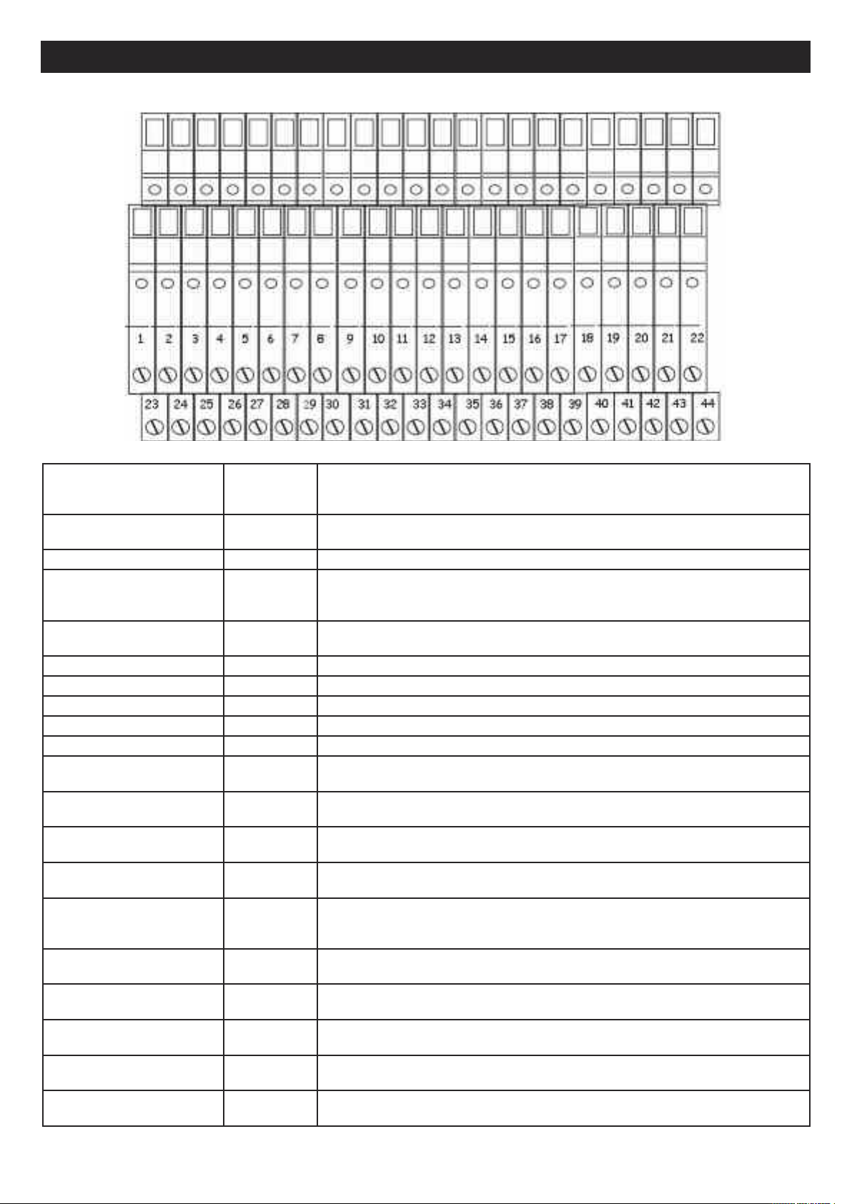
Description Terminals Connection
ADP
(bridge if not used)
DAD (bridge if not used) 3-4 Connect to the DAD fault contact
THA/THS
(bridge if not used)
ED-TOUCH 7-8 + A*-B*
MF PV 9-10 Connect to the NO voltage-free Low Speed Forced Run contact
MF GV 11-12 Connect to the NO voltage-free High Speed Forced Run contact
ARR EST 13-14 Connect to the NO voltage-free External Forced Shutdown contact
BC 15-16-17 BC: Connect to the 3-way valve of the hot water coil (see section IV.12)
BE 18 + DO3** BE: Connect to the static contactor of the electric heater battery (see section IV.14)
Heating pump (PREMIUM
BC)
Cooling pump
(PREMIUM BC)
AL 20 + DO5** 24 V output available if the system is faulty (Caution: max. 24 V 2 A to be connected
DBE 21 + DO6** Connect to the terminals of the contactor for the defrost heater battery (see section
NC (Night cooling)
(LOBBY®)
TRPS (LOBBY®) 23 Agnd* +
DEPS 24 + UI2* Connect to terminals 1 and 3 of the supply DEP (see section IV.8)
1-2 To be connected to the terminals of a firefighter remote shutdown NF contact
5-6 Connect to the NF contact of the THA (PREMIUM CO and INFINITE CO)
Or
Connect to the NF contact of the THA (PREMIUM BE and INFINITE BE)
Connect to the touch screen remote control
(port2)
18 + DO3** Connect to the M/A of the hot water pump (Caution: max. 24 V 2 A to be connected
via relay) (see section IV.12)
19 + DO4** Connect to the M/A of the cold water pump (Caution: max. 24 V 2 A to be
connected via relay)** (see section IV.12)
via relay)
IV.15)
22 + DO7** 24 V output available if the system is configured with the LOBBY EC option for
opening the terminal dampers during Night Cooling operation. (Caution: max. 24 V 2
A to be connected via relay)
Connect to the supply pressure sender (see section IV.9)
UI2*
TRPR (LOBBY®) 25 Agnd* +
UI3*
DEPR 26 + UI3* Connect to terminals 1 and 3 of the return DEP (see section IV.8)
CO2 27 Agnd* UI4* Connect to the CO2 sensor (see section IV.10). For DIVA option.
Connect to the recovery pressure sender (see section IV.9)
59
Page 14
ENGLISH
Description Terminals Connection
BF 28-29-30 BF: Connect to the 3-way valve of the cold water coil (see section IV.12)
DEP FS
DEP FR
RMS 35 + DO1** Connect to terminals 1 and 2 of the motorised supply damper
RMR 36 + DO2** Connect to terminals 1 and 2 of the motorised recovery damper
BIM 37-38-39 Connect to the servo of the motorised bypass (see section IV.5.b)
0-10V S 40-41 Connect to the fan or to the supply variator (see sections VIII.2 and 3)
0-10V R 42-43 Connect to the ventilator or the recovery variator (see sections VIII.2 and 3)
31-32
33-34
Connect to terminals 1 and 3 of the DEP Supply Filter (see section IV.7)
Connect to terminals 1 and 3 of the DEP Recovery Filter (see section IV.7)
* Connect directly to the CORRIGO controller
** Connect directly to the CORRIGO controller and to the DO group (max. 8 A)
IV.5. Electrical connection and operation of the plate heat exchanger
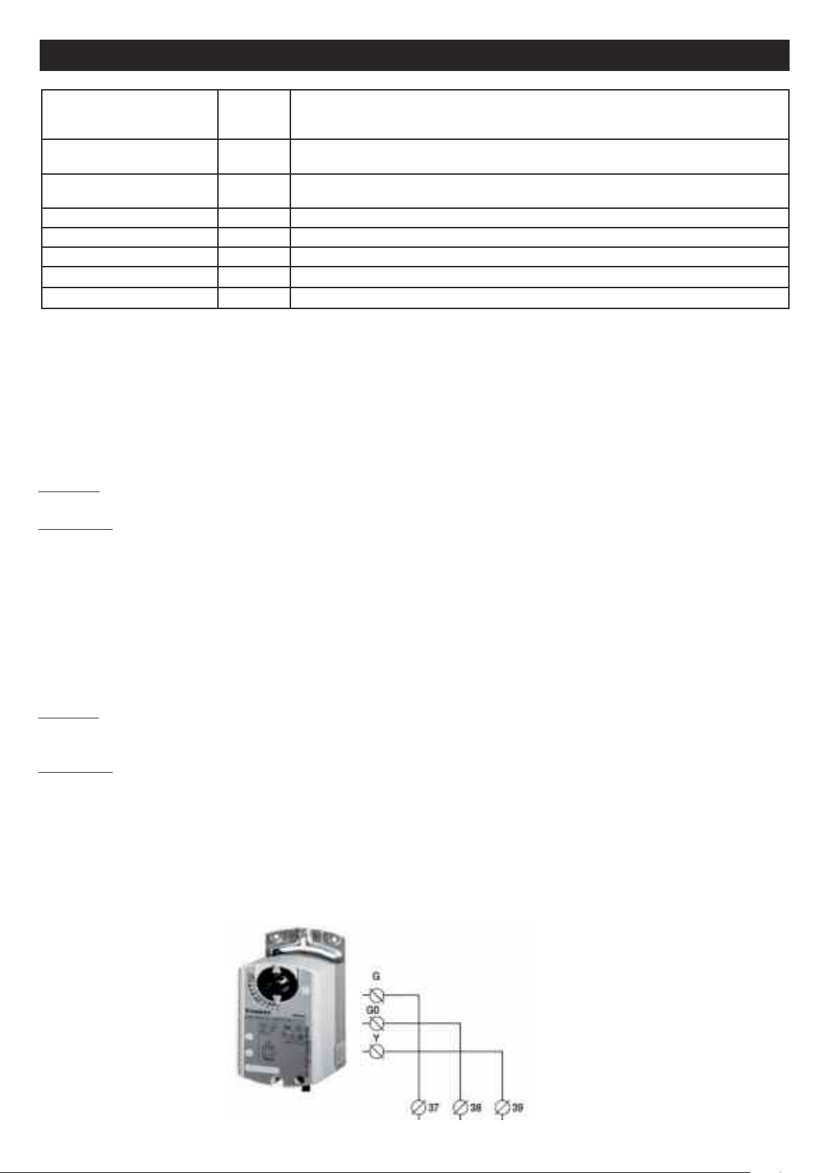
IV.5.a. VORT NRG EC version
The heat exchanger bypass is connected in the factory (see diagram in section IV.2)
The automatic operation of the bypass is controlled by two thermostats:
In winter: If the outside temperature is below 18°C (adjustable), the bypass is closed to recover the maximum amount of
heat.
In summer:
COLD RECOVERY : If the outside temperature is greater than 24°C (adjustable) the bypass is closed to recover the
maximum amount of heat.
FREE COOLING: If the temperature is between 24° and 18° (adjustable), the bypass is opened to allow outside air to flow
in directly
IV.5.b. FIRST PREMIUM INFINITE AND SMART version
The heat exchanger bypass is connected in the factory
Its operation is automatically controlled by the CORRIGO controller and the temperature sensors installed as standard in
our VORT NRG EC systems
In winter: When there is a request for a temperature increase, the bypass closes gradually until fully closed to recover the
maximum amount of heat. In cases where this is not sufficient to reach the set temperature, the heater battery will come
into operation.
In summer:
COLD RECOVERY: If the outside temperature is greater than the inside temperature and there is a request to reduce the
temperature, the bypass closes gradually until fully closed to recover the maximum amount of heat.
In cases where this is not sufficient to reach the set temperature, the cooling coil will come into operation.
FREE COOLING : If the outside temperature is below the inside temperature and there is a request to reduce the
temperature, the bypass opens by a suitable amount (until fully open) so as to allow fresh outside air to enter the building.
In cases where this is not sufficient to reach the set temperature, the cooling coil will come into operation.
60
Page 15
3
1
DEPFR
DEP FS
ENGLISH
DEP
DEP
**
1
3
IV.6. Auto defrost
V.6.a. VORT NRG EC version
I
Defrosting is achieved by opening the bypass the moment the defrost temperature (SDG) falls below 5° C (thermostat
nstalled on exhaust duct). The moment the temperature exceeds the threshold value of +5° C, the bypass re-closes.
i
IV.6.b. FIRST PREMIUM INFINITE and VORT NRG EC EH version
his non-modifiable function is automatically controlled by the CORRIGO controller program and by the sensors fitted as
T
standard in all our dual flow systems. Defrosting is achieved by opening the bypass the moment the defrost temperature
(SDG) falls below 5° C (sensor installed on exhaust duct). If opening the bypass is not sufficient to defrost the heat
exchanger (if the outside temperature is below -10° C), the flow rate of the fresh air fan will be modulated to maintain the
temperature at the defrost sensor at 5° C.
For INFINITE BE and INFINITE BC versions: the defrost heater battery is installed next to the fresh air intake, upstream
of the plate heat exchanger. This maintains the temperature at the heat exchanger at –5°C, thereby reducing the risk of
frost forming while keeping the bypass as closed as possible. This ensures that the system operates at maximum
efficiency. If the action of the defrost heater battery is not in itself sufficient to defrost the heat exchanger, first bypass
modulation and then fan modulation will be implemented, as described above.
IV.7. Connection of the filter pressure switches
The fresh air filter pressure switch is installed and wired in the factory.
IV.8. Connection of the fan pressure switches
The fan pressure switches are wired and aeraulically connected in the factory
*To be
connected if the
DEP does not
detect operation
61
Page 16
TRPS
TRPS
TRPS
ENGLISH
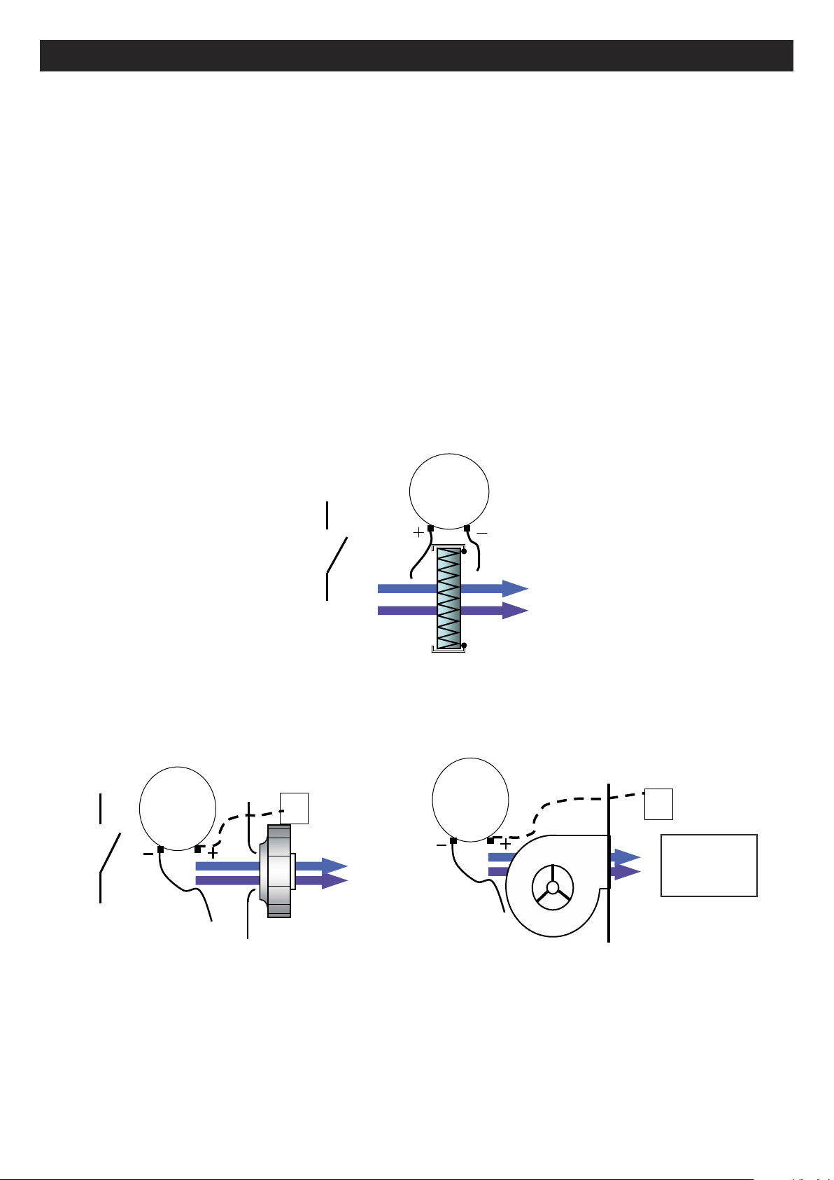
IV.9. Connection of pressure senders for LOBBY®
IV.10. Connection of motors
See sections VIII.2 and VIII.3
WHITE
BROWN
GREEN
BROWN
WHITE
GREEN
LOBBY power supply
Connect to the duct
IV.11. CO2 sender connection
The CO2 sender is factory wired (DIVA option)
White
Brown
Green
62
Page 17
ENGLISH
IV.12. Night Cooling
This function is used in summer to cool building interiors at night using outside air. This helps reduce the quantity of cold
ir required during the daytime. The Night Cooling function only operates from 00:00 to 07:00. During Night Cooling, the
a
hot and cold outputs are locked to 0 V. The heat exchanger delivers exclusively fresh air. On termination of the Night
Cooling stage, the heating is locked to 0V for 60 minutes.
Conditions of operation: definable parameters in section V.5.b.2
• The external temperature exceeds 22° C during daytime
• The timers are set to PV and for shutdown between 00:00 and 07:00.
The external temperature is below 18° C during Night Cooling operation
•
• The external temperature exceeds 10° C during Night Cooling operation
• The ambient room temperature exceeds 18° C
During Night Cooling, the fans run at 85% of full speed. This speed is settable (see section V.5.b.2).
For LOBBY versions, a 24 V output (to be connected by relay) is available across terminals 22 and DO7 to force opening
of the area dampers during Night Cooling.
IV.13. Changeover coil
For PREMIUM BC and INFINITE BC systems. Provision must be made for collection of condensate via a siphon.
Be careful not to impede opening of the access doors (with pipes, cables, etc.)
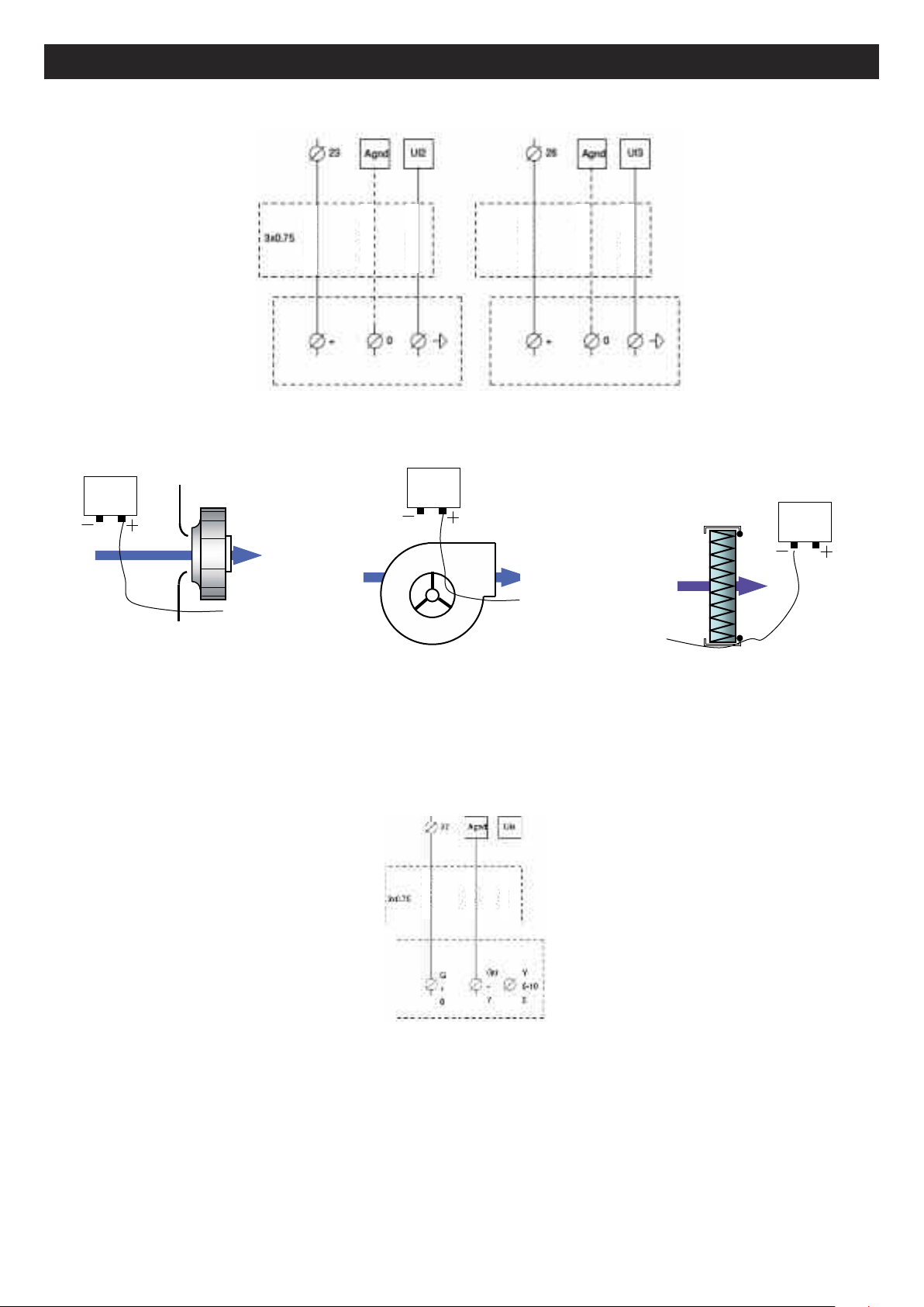
The coil is already installed in the system, the antifreeze thermostat is connected. The 3-way valve must be connected
electrically. If a cooling or changeover battery is used in the duct, move the supply sensor downstream of the coil.
COILS
THE VALVE MUST ONLY BE CONNECTED WHEN THE ELECTRICAL CIRCUIT IS POWERED OFF
Connect the servomotor of the 3-way valve as follows:
Heater battery:
Terminal 15 to +24 V (G) of the valve servomotor
Terminal 16 to 0 V (G0) of the valve servomotor
Terminal 17 to +10 V (Y) of the valve servomotor
Connect the NF contact (C and 2) of the THA (antifreeze thermostat ) to 5 and 6.
Possibility to connect the hot water pump to the system at the terminals DO3 of the controller and connection terminal
18. (Caution: the 24 V output is to be connected via a relay)
Cooling coil:
Terminal 28 to +24 V (G) of the valve servomotor
Terminal 29 to 0 V (G0) of the valve servomotor
Terminal 30 to +10 V (Y) of the valve servomotor
Connect the NF contact (C and 2) of the THA (antifreeze thermostat ) to 5 and 6.
Possibility to connect the cold water pump to the system at the terminals DO4 of the controller and connection
terminal 19. (Caution: the 24 V output is to be connected via a relay)
Changeover coil:
The 3-way plate must be fixed at the water inlet before the bypass.
The 3-way valve and the changeover plate must wired up.
Connect the assembly as follows:
Red wire of the plate (CO) to 10 V (Y) of the valve servomotor
63
Page 18

ENGLISH
Terminal 15 to +24 V (G) of the valve servomotor
Terminal 16 to 0 V (G0) of the valve servomotor
erminal 17 to brown wire of the plate (hot signal)
T
Terminal 30 to black wire of the plate (cold signal)
Connect the NF contact (C and 2) of the THA (antifreeze thermostat ) to 5 and 6.
Possibility to connect the circulator to terminals DO3 of the controller and 18 of the terminal block (higher temperature
required) and to terminals DO4 of the controller and 19 of the terminal block (lower temperature required). (Caution:
the 24 V output is to be connected via a relay)
WARNING: in this case use one relay for each output and wire them in parallel to the M/A of the circulator
IV.14. Direct expansion coil for cooling only or reversible coil
For systems equipped with DX coil, the supplementary module is equipped with a condensate collector. Provision
must be made for collection of condensate via a siphon.
We provide:
• a 24 V output for system heating or cooling requirements
• a 0-10 V hot output and a 0-10 V cold output.
Heating requirement:
• 24 V output: Connect to terminals DO3 of the controller and 18 of the terminal block; allows a startup signal to be
sent to control a DX module (Caution: max. 12 V 2 A to be connected via relay)
• 0-10 V output: Connect to terminals 15 and 16 (15 = 0 V and 16 = 0/10 V)
Cooling requirement:
• 24 V output: Connect to terminals DO4 of the controller and 19 of the terminal block; allows a startup signal to be
sent to control a DX module (Caution: max. 12 V 2 A to be connected via relay)
• 0-10 V output: Connect to terminals 29 and 30 (29 = 0 V and 30 = 0/10 V)
WARNING: If the 24 V outputs are used, use one relay for each output and wire them in parallel to the M/A of the
DX module
WARNING: The 24 V and 0-10 C startup signals do not in any case control the anti-cycle safety function of the
direct expansion coil.
IV.15. Electric heater battery
The electric heater batteries are single-phase units on all the models in the range with the exception of the INFINITE BC
series 2000 and 2500, on which are they are three-phase units.
64
Page 19

ENGLISH
!
!
IV.16. Defrost heater battery
The defrost heater batteries are single-phase units on all the models in the range with the exception of the INFINITE BC
eries 1800 and 2500, on which are they are three-phase units.
s
IV.17. Fire protection function
Refer to parameter settings in section V.6.b.6
There are 2 ways to manage the fire safety function:
• Firefighter shutdown: To be wired between terminals 1 and 2 (volt-free NF contact). Total shutdown of the system
control (plus no selections available).
• Fire alarm: This function allows the supply and recovery fans to be controlled in accordance with the 5 modes
available in the control parameters (this function can be enabled in situ). An alarm appears on the «Fire alarm»
screen
1. “Shutdown”: Total system shutdown
2. “Continuous operation”: Startup or maintenance of the system in HS operation. The fire protection function will
have priority over all other alarms.
3. “Normal operation”: System operation maintained in accordance with parameters defined on site
(Shutdown/PV/GV)
4. “Blower fan only” Startup or maintenance of the blower fan in HS operation (recovery fan stopped)
5. “Recovery fan only” Startup or maintenance of the recovery fan in HS operation (blower fan stopped).
The digital input “Ext shutdown” has priority over the fire protection function.
This function is not suitable for the French market and, in any case, must be approved by an authorised
inspection body.
The digital fire protection input must be connected across terminals DI8 of the controller and 13 of the terminal
block (voltage-free contact mandatory)
IV.18. Dehumidification function
Refer to parameter settings in section V.6.b.7
®
It is possible to associate with the system a COMBIBOX CONCEPT
followed by a heater battery (water, electric or DX heater). In this case the controller will automatically control the heat/cold
ratio required for dehumidification, while maintaining a optimal operating temperature. During a request for cooling,
temperature control has priority over dehumidification.
Function not available in DIVA mode
Connect the coils/batteries as indicated sections IV.12, IV.14
Position the humidity sensor in the ducting at the point of supply or recovery, according to your humidity control mode.
In the case of ambient humidity control for single flow system with recycling, position an ambient humidity sensor in the
building. This must be installed in a neutral position (where it is not affected by external agents)
Connect the humidity sensor as follows:
module: cooling coil (water or cooling-only DX),
65
Page 20

ENGLISH
DEHUMIDIFICATION
HUMIDITY SENDER HR 010
IV.19. MODBUS/WEB/BACNET connection
(refer to parameter settings in section V.6.b)
MODBUS RS485: Use a shielded cable with twin twisted pairs, such as Belden 8723 or equivalent, to connect the BMS
to the controller (connect to port 1 (BANE)/ connect shielding to N and do not connect E)
BACS TCP/IP type BACNET: connect to the TCP/IP port
WEB: connect to the TCP/IP port
BMS: standard
- MODBUS / RS485
- WEB / TCP/IP
- BACNET / TCP/IP
- EXO / TCP/IP
Ext. Disp.
U
O
100 metres
IV.20. Repeater connection
(refer to parameter settings in section V.6.b.2)
A repeater must be used when you connect:
• More than one control panel to the same screen (maximum 6)
• A remote control at a distance of more than 100m
In this case the remote control may be positioned at a maximum distance of 1 km. Connect the repeater and the controller
using a shielded cable with twin twisted pairs, such as Belden 8723 or equivalent. Connect a single-phase 230 V power
supply.
Connect the wires to port 1 as follows:
• B of the repeater to terminal B of the control panel (cable with shielded wire as shown in the diagram below)
• A of the repeater to terminal A of the control panel (cable with shielded wire as shown in the diagram below)
• N of the repeater to terminal N of the control panel (cable with shielded wire as shown in the diagram below)
Single-phase 230 V power supply to provided to the repeater.
66
Page 21

ENGLISH
CONNECTOR
RECOVERY
EARTHEARTH
CONNECTOR
IV.21. LON
(refer to parameter settings in section V.6.b.5). Connect port 2 of the master to port 1 of the LON controller.
BMS: LON
RECOVERY
LON EXTENSION
MASTER
100 metres
Ext. Disp.
V. PARAMETER SETTINGS
V.1. Control (integral or remote control)
The screen has 4 rows of 20 characters. It is backlit. The backlight is not permanently on must it is activated by touch. It
switches off after a period of inactivity.
There are two LEDs on the front of the screen:
Alarm LED with the bell symbol
Write LED with the pencil symbol
- Rapid flashing = the value can be modified
- Slow flashing = a password must be entered in order to modify the value
• The Up, Down, Left and Right arrows keys are used to navigate the menus.
• The Up and Down arrow keys are used to increase or reduce the value of a parameter, while the Right and Left arrow
keys are used to navigate the parameter.
• The OK key is used to enter and confirm a value, while the C key serves to cancel it.
• The alarm key (red) gives access to the predefined list.
• The left arrow is also used to exit the alarms menu and return to the main menu
• The cursors indicate the possible movements and which keys you can press.
%.
!.
67
Page 22

%
!
ENGLISH
Cursor Possibility to scroll up
LARM
A
Arrow
keys for
enu
m
navigation
Possibility to scroll down
V.2. Example parameter settings
• Move the cursor to desired menu
Once you have reached the menu: press OK
and, where required, enter the password.
• Enter the desired value using the arrow keys or the number keypad
• Press OK to confirm and move to the next field.
• Once all the values have been updated, press the left arrow key to return to the initial screen.
V.3. Standard settings (operator menu)
Normal text = read only / Bold text = Can be modified / Bold and underlined text = Can be modified with password
3333 … = not used or not accessible.
WARNING: Do not modify any parameters other than those in bold, otherwise any SAT will not be considered
Analogue input :
Digital input :
Analogue output :
Digital output :
Setting mode
Year:month:day Time
System: function startup or shutdown
SP : T°C Act setpoint : Actual T°C
Operating mode
Temperature
Ventilation control
Humidity control
Schedule setting
Access rights
(10) Language setting (see section V.4.e)
CORRIGO E
Battery/coil type
Control type
PG number
Ventilation
Version :
ID number :
Choose language
Language selection
French (10)
List of main menus that can be accessed
with the password 3333.
The humidity control menu is only available
if the system is configured for humidity
control
68
Page 23

ENGLISH
V.3.a. Operation Mode menu
Operating mode Operating mode
...
Alarm report Alarm log
…
Inputs/Outputs
Operating mode
Auto (7)
Operating period
AS Fan: 00.0 H
Operating period
00.0 H
(Use the down arrow to scroll through the log)
AI
Analogue inputs
AI1: AS T° (supply air)
AI2: Ext T°(external)
AI3: Defrost T°.
AI4: AR T° (recovery air)
DI
Digital inputs
DI1: Al Filter1
DI2: Overheating
or Ext Ant. Prot
DI3: Forced run 1/2
DI4: Forced run 1/1
DI5: Ext stop
(7) Run/Stop setting (see section V.4.d)
UI
Universal inputs
UAI1: Sup. circuit T° (defrost coil)
UAI2: AS press (LOBBY)
UAI3: AR press (LOBBY)
UAI4: CO2 (DIVA)
UDI2: VAS run
UDI3: VAR run
AO
Analogue outputs
AO1: Y1 Heating
AO2: Y2 heat exchanger or M3V
AO3: Y3 Cooling
AO4: VAS Ctrl
AO5: VAR Ctrl
DO1: VAS V freq.
DO2: VAR V. freq
DO3: Electric battery heater or heating
pump
DO4: Cooling pump
DO5: Alarm total
DO6: Sup. control. (DBE)
DO7: Ventilation activated (LOBBY)
69
Page 24

ENGLISH
V.3.b. Temperature control menu
Temperature control
Recovery temperature
Actual :
Sepoint : 21°C (8)
Ext. temp :
Supply temperature
Actual :
Sepoint :
(8) Setting the setpoint temperature (see section V.4.c)
Ref.
Time : 15:54 (1)
Date : 2011-01-25 (1)
Day : Tuesday (1)
Ext. comp. setpoint
-20°C = 25°C (8)
-15°C = 24°C (8)
-10°C = 23°C (8)
Ext. comp. setpoint
-5°C = 23°C (8)
0°C = 22°C (8)
5°C = 20°C (8)
Ext. comp. setpoint
10°C = 18°C (8)
15°C = 18°C (8)
V.3.c. Ventilation control menu
Ventilation control
Frequency control
(ECO or DIVA)
AS manual vent.
Output: 70 (5)
%
or
VAS pressure control
(LOBBY)
Actual : 183Pa (example)
Reference : 180 Pa(5)
Frequency control
(ECO or DIVA)
AS manual vent.
Output: 70 (5)
%
or
VAS pressure control
(LOBBY)
Actual : 183Pa (example)
Reference : 180 Pa(5)
Frequency control
AS manual vent.
Output 1/1 70% (5)
Output 1/2 50% (5)
Frequency control
AS manual vent.
Output 1/1 180Pa (5)
Output 1/2 180Pa (5)
Frequency control
AS manual vent.
Output 1/1 70% (5)
Output 1/2 50% (5)
Frequency control
AS manual vent.
Output 1/1 180Pa (5)
Output 1/2 180Pa (5)
(5) Speed, pressure, flow rate setting (see section V.4.b)
70
Page 25

ENGLISH
V.3.d. Timer setting menu
Schedule setting
Time/Date Time : 15:54 (1)
Normal speed
program
Low speed
program
Date : 2011-01-25 (1)
Day : Tuesday (1)
Normal speed
Monday (2)
Period 1 : 06:00 - 22:00
Period 2 : 00:00 - 00:00
Normal speed
Tuesday (2)
Period 1 : 06:00 - 22:00
Period 2 : 00:00 - 00:00
Etc. to Sunday + vacation
Low speed
Monday (2)
Period 1 : 06:00 - 22:00
Period 2 : 00:00 - 00:00
Normal speed
Monday - Friday (2)
Period 1 : 06:00 - 22:00
Period 2 : 00:00 - 00:00
Low speed
Monday - Friday (2)
Period 1 : 06:00 - 22:00
Period 2 : 00:00 - 00:00
Access rights
Enter
Exit
1. Setting the time and date (see section V.4a)
2. Setting the LS schedule (see section V.4a)
3. Setting the HS schedule (see section V.4a)
4. Setting vacation periods (see section V.4a)
Low speed
Tuesday (2)
Period 1 : 06:00 - 22:00
Period 2 : 00:00 - 00:00
Etc. to Sunday + vacation
Enter password
For the required authorization level :
****
Current lev. :
Leave this access level?
NO or YES
Current lev. :
71
Page 26

ENGLISH
!
V.4. Modification of operator parameters (password 3333 required)
.4.a. Setting different time and date clocks
V
.4.a.1. Date and time o the CORRIGO controller[(1) section V.3.d]
V
Access: Timer/Time Date Setting
he date and time of the controller are pre-set in the CORRIGO. The changeover between the Summer and Winter
T
schedules is managed automatically.
V.4.a.2. Programming system operation times [(2) (3) chapter V.3.d]
ccess:
A
• Normal speed pgr: Times/normal speed program setting
• Low speed pgr: Times/low speed program setting
The system is programmed to operate a normal speed (HS-1/1) 07:00 - 22:00 at low speed (LS-1/2) 22:00 - 06:00 except
for DIVA / LOBBY versions, which permanently operate at low speed (LS-1/2)
As shown in the diagram, it is also possible to modify the periods from Monday to Friday, by pressing the right-hand
button when on the Monday screen
Note: if low speed (LS-1/2) and normal speed (HS1/1) are both active in the same time period, the system will operate in
HS
Operating exceptions:
DIVA: In order for the CO2control function to work, there must be no active time periods in normal speed (HS1/1)
LOBBY: Only the low speed timer (LS-1/2) must be active.
NIGHT COOLING: This function is only active when the system is operating in low speed (LS-1/1)
or stopped between 00:00 and 07:00. (Example: If the system is in low speed (LS-1/2) between 02:00 and 06:00
and in normal speed (HS-1/1) for the rest of the time. In this case, the NIGHT COOLING function will only operate
from 02:00 to 06:00)
V.4.a.3. Vacation period [(4) section V.3.d] (password 3333 required)
Access: Setting Timers/Vacations
The system has no pre-set vacation periods. If you wish to reduce the operating times during vacations, set the operating
periods for vacations as described in section V.3.4), then set the vacation days.
V.4.b. Modifying the speed/pressure for LS and HS operation
V.4.b.1. STANDARD (ECO)/DIVA [(5) section V.3.c]
Access: VAS 1/1 and 1/2 Ventilation control/Frequency control or VAR 1/1 and 1/2 Frequency control
You can change the rotation speed of each fan in the system to LS-1/2 (low speed) and HS-1/1 (high speed) in order to
adjust the air flow rate.
• To adjust the initial flow rate (HS-1/1), set the system to normal speed using the available “Forced HS” terminals
(bridge across terminals 11 and 12).
• To adjust the initial LS flow rate, set the system to low speed using the available “Forced LS” terminals (bridge
across terminals 9 and 10).
V.4.b.2. LOBBY [(5) section V.3.c]
Access: VAS 1/2 ventilation control/pressure control or VAR 1/2 pressure control
You can change the constant system pressure for each fan in order to adjust the flow rate.
To adjust the initial LS flow rate, set the system to normal speed using the available “Forced LS” terminals (bridge across
terminals 9 and 10).
72
Page 27

ENGLISH
!
V.4.c. Modifying the temperature setpoint
[(8) section V.3.b]
Access: Temperature control
The setting is based on the temperature of:
• the supply with external compensation (standard setting). In other words, the setpoint for the temperature changes
ccording to the external temperature. This rule is defined in order to comply with RT 2012
a
• Recovery.
V.4.d. Forced shutdown of control unit or forced LS or HS operation on the remote control
(7)section V.3.a]
[
Access: Operating mode/Operating mode
It is possible to stop (7) (shut down) the system via the CORRIGO command or execute a forced LS (7) (manual speed
1/2) or HS (7) run (manual speed 1/1). As standard, the system operates in Automatic mode controlled by the timers
(7) (Auto)
An alarm will be generated the moment the system is taken out of Auto mode. Note that the manual speed 1/1
and manual speed 1/2 modes are used exclusively for activation and repairs. Any other setting will cause a
system malfunction.
V.4.e. Language selection
[(10) section V.3]
Access: Initial screen/Language selection
V.5. Intermediate settings (function level)
In order to modify the setting type, the Night Cooling parameters and CO2setpoint you need access to the configuration
menu at system level. This requires authorization to access the “Function” level. The procedure is as follows.
Access rights Enter Enter the password 2222
Enter the code 2222 using the arrow keys then press OK to confirm. Press the left arrow key twice to access the menus.
If you make a mistake, press C twice and repeat the operation.
V.5.a. Configuration menu with function level access
Configuration Control function
Ventilation
For the required authorization level :
Current lev. : FUNCTION
Control function
Mode :
Supply + ext. comp (1)
Ventilation active : YES (2)
Ext. temperature activation : 22°C (2)
Night external T°
High 18°C (2)
Low 10°C (2)
Mini ambient temp : 18°C (2)
Speed : 85%
CO2/COV ctrl active :
CO2/VO Ctrl
Run timer yes
Type Fan
Speed 1/2 : 800 ppm (3)
Speed 1/1 : 1000 ppm (3)
Diff : 160 ppm
1. Selection of the setting type (see section V.5.b.1)
2. Modification of Night Cooling parameters (see section V.5.b.2)
3. Modification of CO2setpoints (DIVA and QUATTRO only) (see section V.5.b.3)
73
Page 28

ENGLISH
V.5.b. Modification of function parameters (password 2222 required)
V.5.b.1. System control mode
(1)section V.5.a]
[
Access: Configuration/Control function
The control type is pre-set in the CORRIGO to supply with external compensation It is also possible to switch to recovery
ontrol mode.
c
WARNING: if you wish to set the system according to an ambient temperature, select “Recover Ctrl” mode; any
(
other option will cause a system malfunction)
V.5.b.2. Ventilation parameters
[(2)section V.5.a]
Access: Configuration/Ventilation
The ventilation speed is pre-set to 85%. This value can be modified. It is also possible to modify the temperature for
activation of Night Cooling (daytime external temperature/day, etc.) and deactivate it.
V.5.b.3. CO2 setpoint for DIVA QUATTRO option
[(3)section V.5.a]
Access: Configuration/Ctrl CO2/COV
The CO2 setpoints are pre-set: LS = 800 ppm HS = 1000 ppm. When the CO2level reaches 1000 ppm, the system will
increase the operating speed proportionally up to its maximum speed.
V.6. Administrator settings
Activation of the communication, dehumidification and fire protection functions requires access to the configuration
menu at system level. Authorization for “Admin” level access is required. Proceed as follows:
Access rights Enter Enter the password 1111
Enter the password 1111 using the arrow keys and press OK to confirm. Press the left arrow key twice to access the
menu. In case of error, press C twice and repeat the operation.
For required authorization
Current level: ADMIN
74
Page 29

ENGLISH
V.6.a. Configuration menu with admin level access
Configuration Communication
System
Port 1:
Slave
TCP/IP
Modbus slave
communication
Port 1
Active (1)
Bacnet MSTP
communication Port
1
Active (3)
DHCP: YES (5)
Current Ip:
Bacnet IP
communication
Active (7)
Modbus address: 1 (2)
Speed: 9600 Bps (2)
2 stop bits: Yes (2)
Parity No (2)
Device name: - (4)
Mac: 0 (4)
Low device ID: 2640 (4)
High device ID: 0 (4) (x10000)
Speed: 9,600 Bps (4)
Master max ad.: 127 (4)
IP - (6)
Subnet Mask - (6)
Subnet Mask - (6)
Gateway - (6)
Device name: - (8)
BBMD address: 0 (8)
Low device ID: 2640 (8)
High device ID: 0 (8)
(x10000)
UDP low port N° 7808(8)
UDP high port N° 4(8)
(x10000)
Addresses
PLA: 254 (9)
ELA: 254 (9)
1 and 2 Activation of MODBUS RS485 and settings (see section V.8)
3 and 4 Activation of BACNET MSTP and settings (see section V.8)
5 and 6 ITCP/IP settings (see section V.8)
7 and 8 Activation of BACNET IP and settings (see section V.8)
9 Repeater addressing (see section V.8)
V.7. Modification of function parameters
V.7.a. MODBUS
A simplified MODBUS is presented at the end of the operating and commissioning instruction manual.
Access: Configuration/Communication
MODBUS TCP/IP is activated as standard in DHCP. It is possible to know the DHCP address or set the fixed IP [(5)(6)
section V.6], Modbus port= 502/Device ID = 255
It is necessary to activate the MODBUS RS 485 [(1) section V.6]. Possibility to set speed, parity, stop bits, etc. [(2) section
V.6].
Modbus type
1 = Coil status register (Modbus function 1, 5 and 15)
2 = Input status register (Modbus function 2)
3 = Company register (Modbus function 3, 6 and 16)
4 = Input register (Modbus function 4)
75
Page 30

ENGLISH
Modbus functions supported
Read coils (1)
Read separate input (2)
ead company registers (3)
R
Read input registers (4)
Write single coils (5)
Write single register (6)
Write multiple coils (15)
rite multiple register (16)
W
XOL type
E
R = Real (-3.3E38 – 3.3E38)
I = Integer (-32768 – 32767)
X = Index (0 – 255)
L = Logic (0/1)
Transmission mode
The control unit is set to RTU mode
A maximum of 47 registers can be read in one message.
V.7.a.1. Repeaters and EXO communication
[(3) section V.6]
Access: Configuration/System
The repeater is supplied with an instruction manual for setup and operation If multiple CORRIGO modules are connected
to the same remote control (up to 6 CORRIGO modules), it will be necessary to modify the PLA/ELA on each CORRIGO.
In this case, a different address must be entered in the repeated for each CORRIGO module Follow the instructions given
in the setup and operation instruction manual.
V.7.a.2. WEB communication
It is possible to communicate via TCP/IP WEB in language. In this case, the device is supplied with the Internet page and
the controller set to DHCP.
It is possible to know the DHCP address or set the fixed IP [(5)(6) section V.7], or using the E-tool software
http://www.regin.se
V.8.a.3. BACNET IP communication with BASC type
A simplified BACNET is presented at the end of the operating and commissioning instruction manual.
Access: Configuration/Communication
It is necessary to activate the BACNET IP [(7) section V.6]. It is possible to know the DHCP address or set the fixed IP
[(5)(6) section V.6] It is possible to set the ID / Port N° … [(8) section V.6].
It is necessary to activate the BACNET MSTP (3) section V.6]. Possibility to set speed, ID, address, etc. [(4)section V.6].
Speed = 9600/MAC address = 0/Device ID = 2640/Max master = 127
BACnet type
10XXX = Binary read and write
20XXX = Binary read
10XXX = Analogue read and write
40XXX = Analogue read
30XXX = Multistate read and write
40XXX = Multistate read
(XXX = MODBUS address)
AV = Analogue value
BV = Binary value
MSV = Multistate value
BMMD address: The BBMD address is used to locate devices connected to different BACnet/IP subnetworks and
separated by an IP router. The address is entered as he host; the host can be the host name if DNS is configured. If the
DNS is not configured, it will be necessary to enter the host address in the format xxx.xxx.xxx.xxx followed by the port
number (default setting 47808)
MAC: The MAC address of the device. This must be unique for the sub-network only.
76
Page 31

ENGLISH
Device ID: The ID of a device, used to identify it on the BACnet. This number must not be duplicated anywhere else on
the BACnet and therefore must be unique. To set an ID value of 34600, the low number must be set to 4600 and the high
number to 3
For more information, refer to the CORRIGO images at http://www.regin.se
V.8.a.4. LON communication (if CORRIGO with LON option)
Set the LON function as follows:
In the menu Configuration/Communication/Function port 2 = activate port 2 in the extension unit.
Go to the right and activate the extension unit. 1 in CORRIGO E28 LON
The button for the PIN service is located on the rear of the controller.
The communication table is located at http://www.regincontrols.com
V.8.a.5. Activation of fire protection function
Setting the input parameters
Access: Configuration/Input Output/DI/ DI8
Declare input DI8 as “Fire Al” “NO”
Definition of function parameters
Access: Configuration/Fire protection function
Select the required operating mode to be activated when the fire protection function is activated
“Shutdown”: Total shutdown of the unit
“Continuous operation” Startup or maintenance of unit operation in HS mode.
The fire protection function will have priority over all other alarms.
“Normal operation”: the unit will continue to operate within the parameters selected on site (stop/LS/HS)
“Exhaust fan only”: Start or maintain exhaust fan operation in HS mode (the recovery fan is stopped)
“Recovery fan only”: Start or maintain recovery fan operation in HS mode (the exhaust fan is stopped)
Alarm setting
Access: Configuration/alarm configuration
Enter alarm number “10”, go to the right and enter in priority “C alarm C” “Active”
V.8.a.6. Activation of the dehumidification function
Input settings
Access: Configuration/Input Output/UI/ UI4
Declare input UI4 “Ambient humidity”
Function setting
Access: Configuration/Humidity control
“Select dehumidification”
Reference value setting
Access: Humidity control
Enter the desired setpoint
77
Page 32

ENGLISH
VI. PROBLEM SOLVING
VI.1. Different types of fault
The EASY setting on VORT NRG EC / EC H systems is equipped with alarms. When the red LED flashes, press the alarm
utton (red) to view the fault.
b
he fault will either be class A or class C (see detailed information below)
T
Fault type:
A: The fault causes the ventilation system to shut down. The device will not function until the problem has been resolved
nd the fault eliminated.
a
: The fault does not cause the ventilation system to shut down and the alarm will be reset automatically once the
C
problem has been resolved. To cancel a fault, press the alarm key (red), then “cancel” and “log” the fault using the arrow
keys and press OK. Warning: do not “lock”
Description Cause
The CORRIGO screen does not
switch on
The fan/s does/do not work - The timers are on 0
The remote control does not work
or sends incorrect values
- The system is not receiving sufficient power (P/B LED of the CORRIGO off)
- To illuminate the screen, press a key (backlighting).
- The control fuse is out of service
- No external run command
- External shutdown
- Alarm active
Remote control at distance > 100 m
Repeater not connected correctly.
78
Page 33

ENGLISH
VI.2. Alarms list
N°
Title Description Type Time Cause
1 AS fan fault (UDI2 must be
closed “Fer” if the
fan is in in
operation)
Or
UAI2 should be
over 30 Pa if the
fan is in in
operation)
2 2 AR fan
fault
6 Filter
obstructed
8 External frost
protection
15 High supply
temp.
23 Heater batt.
overheating
27 Ext. temp
sensor error
31 VAS pressure
error
32 VAR
pressure
error
(UDI3 must be
closed (“Fer”) if
the fan is in
operation )
Or
UAI3 should be
over 30 Pa if the
fan is in in
operation)
DI1 should be
open (“Ouv”) in
the absence of
faults
Ext DI3 should be
closed (“Fer”) in
the absence of
faults
Ext AI1 has
exceeded 50° C
Ext DI3 should be
closed (“Fer”) in
the absence of
faults
Check the value
on Ext Al2
Difference of more
than 50 Pa
between the
supply setpoint
and the
temperature
reading on Ext
UAI1
Difference of more
than 50 Pa
between the
supply setpoint
and the
temperature
reading on Ext
UAI2
A 30 s
(120 s
for
LOBBY)
A 30 s
(120 s
for
LOBBY)
C 5 s 1. The filter/s is/are obstructed
C 120 s 1. The THA thermostat is not set to 5° C
A 30 s 1. The supply temperature has exceeded 50° C
A 5 s 1. The THS safety thermostat has tripped. To reset the THS, press the
A 5 s 1. The external temperature sensor is out of service
C 30 min The supply network does not correspond to the selected fan or to the
C 30 min The recovery network does not correspond to the selected fan or to the
1. The pressure switch is connected incorrectly (the pressure switch
must be set to 30 Pa).
2. The pressure detected by the sender is lower
3. then 30 Pa (LOBBY
4. The motor is out of service
5. The thermal protection of the motor has tripped
6. Check the connections of the clear plastic pipes (see IV.8 and IV.9)
7. Water in clear plastic pipe
8. 0-10 V motor inverted
2. The pressure switch/es is/are connected incorrectly (the pressure
switches should be set to 150 Pa for G4 200 Pa for F7).
3. Check the connections of the clear plastic pipes (see section IV.8)
2. The THA thermostat is out of service
3. The circulation pump is out of service
4. The 3-way valve is incorrectly wired or hydraulically connected or out
of service
2. The temperature setpoint is too high
3. The supply fan has stopped (AS fan fault) while the heater battery is
working at full operating speed.
reset button on the electric heater battery.
2. Power supply failure
3. The supply fan has stopped (AS fan fault) while the heater batter is
working at full operating speed.
2. The external temperature sensor SEG is wired incorrectly (see section
IV.3)
pressure setpoint.
The filter is obstructed
pressure setpoint.
The filter is obstructed
®
) (contact technical assistance)
®
) (contact technical assistance)
79
Page 34

ENGLISH
N°
Title Description Type Time Cause
35 Manual Operation in
manual mode
from
...in manual
6
3
to
44
48 Low charge Internal battery
49 AS temp
50 AR temp
55 VAS pressure
56 VAR pressure
59 CO2 sensor
85 ...in manual
86 Carry out the
87 ...in manual
ode
m
sensor error
sensor error
sensor error
sensor error
error
mode
servicing
operation
mode
Some functions
ave switched to
h
manual mode.
error
Check value on
Ext Al1
Check value on
Ext Al3
Check value on
Ext UAI1
Check value on
Ext UAI2
Check value on
Ext AI 4
Some functions
have switched to
manual mode.
Periodic
inspection
Some functions
have switched to
manual mode.
C 5 s Fault for information only (the system has switched to shutdown in PV
or to PG directly on the display (see (7) section V.3.a)
C 5 s In the Manual/Auto menu all options should be set to Auto.
A 5 s The internal battery of the CORRIGO is faulty.
Change the battery so as not lose the program.
See section VII.2
A 5 s The SSG external temperature sensor is out of service
The SSG external temperature sensor is wired
incorrectly (see section V.3.a)
A 5 s The SRG external temperature sensor is out of service
The SRG external temperature sensor is wired
incorrectly (see section V.3.a)
A 5 s The 0-10 V signal is inverted
The fresh air pressure sender is short-circuited
A 5 s The 0-10 V signal is inverted
The recovery air pressure sender is short-circuited
A 5 s The 0-10 V signal is inverted
The CO2 pressure sender is short-circuited
A 5 s In the Manual/Auto menu all options should be set to Auto.
C 5 s See section VI.3
C 5 s In the Manual/Auto menu all options should be set to Auto.
VI.3. Cancelling the “Servicing required” alarm
For these parameter settings, it is necessary to access the setting menu. This requires authorization to access the
“Function” level.
The procedure is as follows.
Access rights Enter Enter the password 2222
Enter the code 2222 using the arrow keys then press OK to confirm. Press the left arrow key twice to access the menus.
If you make a mistake, press C twice and repeat the operation.
Settings RAZ filter counter Filter alarms
A service alarm is generated every 6 months. Enter YES to reset the counter.
80
For the required authorization level :
Current lev. : FUNCTION
Reset the
Timer : YES
Page 35

ENGLISH
VII. MAINTENANCE
VII.1. Essential maintenance
System exterior
Check the ducts, flexible hoses and dampers and renew if necessary. Check that all the components connected to the
ystem are positioned in such a way that vibration is not transmitted to external elements.
s
ystem and controls
S
very year check the electrical connections.
E
Filtration
Do not damage the filter element
Classification
Gravimetric EU4 G4 Limited (from 1 to 4 times) YES
Opacimetric EU7 F7 NO
Components 1 MONTH 3 MONTHS 6 MONTHS 12 MONTHS
Filtration Supply
Filtration efficiency
EUROVENT
(for G4 filters)
Reference
Cleaning
(for G4 filters)
(Water + weak detergent)
Servicing interval
Washing*
Cleaning
(for G4 filters)
Aspiration*
Supply*
Filter replacement
VII.2. Battery replacement
When the low charge alarm appears and the red light illuminates, this indicates that the emergency battery that provides
backup power for the memory and clock is running low. To replace the battery proceed as follows. A condenser protects
the timer and allows it to run for approximately 10 minutes after a power failure. If the battery replacement operation takes
less than 10 minutes, it will not be necessary to reload the programme and the timer will continue to function normally.
The battery type is CR2032
Using a small screwdriver, press in the clips on each side of the battery housing to remove the cover from the base. Hold
the base and remove the cover.
Battery position
Grip the battery and gently pull it upwards to remove it from its housing.
Press the new battery firmly into its support. Note: Be careful to install the battery the right way round to respect the
polarity.
81
Page 36

ENGLISH
VIII. APPENDICES
VIII.1. Control diagram
4P4C
conn.
Modular
Ext. disp.
RS485
PORT 2
RS485
PORT 1
This document is our property and may not be reproduced without prior authorisation.
82
FUSE TERMINAL
Page 37

ENGLISH
VIII.2. Connection of motors for VORT NRG EC / EC EH 600 - 800
CONNECTOR
RECOVERY
ARTH
E
ARTH
E
CONNECTOR
RECOVERY
VORT NRG EC
CONNECTOR
SUPPLY
EARTH
EARTH
CONNECTOR
SUPPLY
83
Page 38

ENGLISH
VIII.3. Connection of motors for VORT NRG EC / EC EH 1500-2000-2500
RECOVERY
RECOVERY
EARTH
ARTH
E
VORT NRG EC
84
SUPPLY
EARTH
EARTH
SUPPLY
Page 39

ENGLISH
N
EOTIME
®
600
0
2
00
4
00
6
00
800
1000
100 200 300400500600
D
ébit (m
3
/
h)
Pression statique (Pa)
100%
9
0%
80%
7
0%
60%
5
0%
40%
NEOTIME® 900
0
200
400
6
00
800
0
09008007006005004003002
Débit (m3/h)
Pression statique (Pa)
100%
90%
8
0%
7
0%
60%
50%
4
0%
NEOTIME® 1300
0
100
200
300
400
500
400 600 800100012001400
Débit (m3/h)
Pression statique (Pa)
MAX = 90 %
80%
70%
60%
60%
40%
VIII.4. Graphs
ORT NRG EC / EC EH 600
V
Static Pressure (Pa)Static Pressure (Pa)
Flow rate m3/h
VORT NRG EC / EC EH 800
Static Pressure (Pa)
VORT NRG EC / EC EH 1500
Flow rate m3/h
Flow rate m3/h
85
Page 40

ENGLISH
NEOTIME® 1800
0
1
00
200
3
00
400
500
0
00200810061004100210001008006
Débit (m3/h)
Pression statique (Pa)
100%
9
0
%
80%
7
0
%
6
0%
5
0%
N
EOTIME
®
2500
0
100
2
00
300
4
00
5
00
0052052200020571005105210001
Débit (m3/h)
Pression statique (Pa)
100%
90%
80%
7
0%
60%
5
0%
Static Pressure (Pa)
ORT NRG EC / EC EH 1800
V
Flow rate m3/h
VORT NRG EC / EC EH 2500
Static Pressure (Pa)
Flow rate m3/h
86
Page 41

ENGLISH
VIII.5. MODBUS and BACNET table
III.5.a. MODBUS information
V
Introduction
Corrigo E ventilation is a pre-programmed application for control of an air handling unit (CTA). The Corrigo E controller
an either be used as a stand-alone unit or integrated in an existing EXO project. In both cases it is configured via the
c
display or using the configuration tool E tool on a PC. This document describes all the signals that can be accessed via
EXOline or Modbus. This document does not describe how to create an EXO system.
Signal types
All signals that are accessible from a SCADA system are described in this document. The signals that have a default value
are parameter settings that can be changed from SCADA. The signals without default values are actual values and cannot
be changed from SCADA.
EXOL type
EXOL type signals:
R = Real number with decimal point (Real) (-3.3E3S -3.3E38)
I = Whole number (Integer) (-32768 -32767)
X = Index (0 - 255)
L = Boolean (Logic) (0/1)
Modbus type
Modbus type signals:
1 = Coil Status Register (Modbus function = 1.5 and 15)
2 = Coil Status Register (Modbus function = 2 and 15)
3 = Holding Register (Modbus function = 3. 6 e 16)
4 = Input Register (Modbus function = 4)
Compatible Modbus functions:
1 = Read Coils
2 = Read Discrete Input
3 = Read Holding Register
4 = Read Input Register
5 = Write Single Coil
6 = Write Single Register
15= Write Multiple Coils
16= Write Multiple Registers
Max. 47 registers
A maximum of 47 registers can be read in one message.
Communication limits
The Modbus master must wait for a minimum of 3.5 charactertimes (4 ms at 9600 bps) between two messages. When
the Modbus master communicates with more than one Corrigo E controller on the same communication line (RS485), the
Modbus master must wait for a minimum of 14 charactertimes (16 ms at 9600 bps) between the answer and the first
question for the next controller.
The Corrigo E controller has a limit of 10 fast communications every 30 seconds, while other communications will have a
answering delay of approximately 1 second.
Scale factor Modbus
All real signals (decimal) have scale factor 10, except the time settings signals that have scale factor 100 and Air flow
signals that have scale factor 1 for Modbus communication. Integer, Index and Logic signals have scale factor 1.
Modbus activation
The Corrigo controller uses the same port for both Modbus communication and EXOline communication. If you try to
communicate with a Modbus-activated unit using E tool or another type of EXOline communication, the input port will will
automatically adapt itself after approx. one second. The port will remain in EXO-mode until 10 seconds of communication
inactivity have passed after which it will revert to Modbus mode.
87
Page 42

ENGLISH
Modbus Connection
The Modbus protocol consists of several layers (OSI model). The bottom layer is the physical layer, and is comprised of
a number of wires and signal levels. The next layer describes the communication digits (number of data bits, stop-bits,
parity, etc). Next are the layers describing the specific functions of the Modbus protocol (number of digits per message,
he meanings of different messages, etc).
t
or Modbus, the physical layer can be RS485, RS422 or RS232.
F
xample
E
The simplified example below illustrates the master-slave relationship. In addition, checksums for message validation are
lso transmitted in both query and answer.
a
Computer running a Modbus master application
Query:
“Read from point
address x on Slave
address 2”
Corrigo E
Slave Address: 1
Modbus/RTU
9600 baud
Parity: none
2 stop bits
Answer:
“Slave address 2 contains
value z on requested point
address”
Corrigo E
Slave Address: 2
Modbus/RTU
9600 baud
Parity: none
2 stop bits
Configuration
The first important things to configure are the communication parameters for the Modbus line. As described earlier, these
parameters must be identical in the master unit and the slave units, since they define the structure of messages and the
transmission speed.
The default configuration values of a Corrigo E controller are shown in the figure below.
Corrigo E is by default set to Slave Address 1. For each other unit added, a new Modbus address can be set using the
Corrigo E display or E tool.
88
Page 43

ENGLISH
Transmission mode
The Corrigo E uses RTU transmission mode (not to be confused with ASCII mode). The parameter settings for the
transmission mode must be the same in the master unit and the slave units, since the Modbus/RTU configuration is not
compatible with Modbus/ASCII settings. The configuration parameter word length is always 8 for the Modbus/RTU
onfiguration.
c
Writing values
To modify the Corrigo E output values, set the output to manual mode using a Modbus signal. Then set the corresponding
..._ManSet signal to the desired level. These signals are described in section 5: Holding Registers Note: only parameters
with default values can be modified. These are indicated in the Coil Status Register and Holding Register sections.
Reading values
An effective way to read values is to read multiple variables simultaneously. For example, to read all analogue outputs,
set the Modbus query to the values shown in the figure below. The first analogue output variable starts at address 54
(QAnaOut.AQ1). To read the addresses 54 to 58, set the length to 5. The Modbus answer will include all 5 values in just
one message, making the communication more effective.
VIII.5.b. BACNET description
BACNET type
BACnet signal types:
10XXX = Binary read and write
20XXX = Binary read
10XXX = Analogue read and write
40XXX = Analogue read
30XXX = Multistate read and write
40XXX = Multistate read
(Where XXX = Modbus address)
NOTE: In the list of variables in this manual the following abbreviations are used:
AV = Analogue value
BV = Binary value
MSV = Multistate value
The names of the BACnet objects are the same for EXOL type objects, but are abbreviated by eliminating the “Cor” prefix
(e.g.: “VentSettings.CorOverHeatFastStop” becomes “VentSettings.OverHeatFastStop”, etc.).
89
Page 44

ENGLISH
Addressing
he figure below illustrates how BACnet addressing is presented E tool.
T
BACnet/IP = Activation status of the BACnet/IP protocol.
Name of the BACnet device = the name of the device.
The ID of the device is divided into two parts: one low and one high. For example: If the high part of the ID is “1”, the
device ID would be “00012640”.
Low ID of the BACnet device = the lower part of the device identification.
High ID of the BACnet device (x 10000) = the higher part of the device identification.
The port number is divided into two parts: on low and one high For example: In the illustration above, the port number is
“47808”.
Low BACnet/IP FIDP port number = port number, low part.
High BACnet/IP FIDP port number (x 10000) = port number, high part. This is the designated port for communication.
BBMD address = Address of the BACnet transmission control device. This is used for internet communication between
devices with BACnet.
90
Page 45

ENGLISH
VIII.5.c. TABLE
INPUT REGISTER
unction
F
System status Modbus:
External temperature R 1 AV,40001
escription
D
0= stop
1= startup
2= low speed startup
3= maximum speed startup
4= normal speed startup
5= in operation
8= o CO2 operation
9= Night cooling
11= shutting down
BACNET:
1= stop
2= startup
3= lo speed startup
4= maximum speed startup
5= normal speed startup
6= in operation
9= CO2 operation
10= Night cooling
12= shutting down
xo typeModbus
E
address
X 3 MSV,40003
acnet
B
address
efault
D
value
Operating temperature of the
blower fan
Operating temperature of the
recovery fan
Supply temperature R 7 AV,40007
Extraction temperature R 9 AV,40009
Fresh air pressure LOBBY EC R 13 AV,40013
Recovery air pressure LOBBY EC R 14 AV,40014
CO2 DIVA R 17 AV,40017
Defrost temperature R 21 AV,40021
Humidity R 23 AV,40023
Defrost heater temperature R 25 AV,40025
Analogue output 0-10 V heating (WATER COIL) R 54
Analogue output 0-10 V Heat exchanger R 55
Analogue output 0-10 V Heat exchanger R 56
Analogue output 0-10 V Supply R 57
R 4 AV,40004
R 5 AV,40005
Analogue output 0-10V Recovery R 58
91
Page 46

ENGLISH
HOLDING REGISTER
Function Description Exo type Modbus
address
Supply setpoint Configured as constant supply R 1 AV,30001 18
Supply setpoint Configured as Ext.comp supply for ext T°C of –20° C R 10 25
Supply setpoint Configured as Ext.comp supply for ext T°C of –15° C R 11 24
Supply setpoint Configured as Ext.comp supply for ext T°C of –10° C R 12 23
Supply setpoint Configured as Ext.comp supply for ext T°C of –5° C R 13 23
Supply setpoint Configured as Ext.comp supply for ext T°C of –0° C R 14 22
Supply setpoint Configured as Ext.comp supply for ext T°C of +5° C R 15 20
Supply setpoint Configured as Ext.comp supply for ext T°C of +10° C R 16 18
Supply setpoint Configured as Ext.comp supply for ext T°C of +15° C R 17 18
Recovery setpoint Configured for recovery control R 18 AV,30018 21
HS supply speed setpoint In % for ECO and DIVA models R 424 70
LS supply speed setpoint In % for ECO and DIVA models R 425 50
HS recovery speed setpoint In % for ECO and DIVA models R 426 70
LS recovery speed setpoint In % for ECO and DIVA models R 427 50
Supply pressure setpoint In Pa for LOBBY model R 25 AV,30025 150
Recovery pressure setpoint In Pa for LOBBY model R 27 AV,30027 150
Normal speed timer Start normal speed period 1 MONDAY (HH.MM) R 40 xx:xx
Normal speed timer Stop normal speed period 1 MONDAY (HH.MM) R 41 xx:xx
Normal speed timer Start normal speed period 2 MONDAY (HH.MM) R 42 xx:xx
Normal speed timer Stop normal speed period 2 MONDAY (HH.MM) R 43 xx:xx
Normal speed timer Start normal speed period 1 TUESDAY (HH.MM) R 44 xx:xx
Normal speed timer Stop normal speed period 1 TUESDAY (HH.MM) R 45 xx:xx
Normal speed timer Start normal speed period 2 TUESDAY (HH.MM) R 46 xx:xx
Normal speed timer Stop normal speed period 2 TUESDAY (HH.MM) R 47 xx:xx
Normal speed timer Start normal speed period 1 WEDNESDAY (HH.MM) R 48 xx:xx
Normal speed timer Stop normal speed period 1 WEDNESDAY (HH.MM) R 49 xx:xx
Normal speed timer Start normal speed period 2 WEDNESDAY (HH.MM) R 50 xx:xx
Normal speed timer Stop normal speed period 2 WEDNESDAY (HH.MM) R 51 xx:xx
Normal speed timer Start normal speed period 1 THURSDAY (HH.MM) R 52 xx:xx
Normal speed timer Stop normal speed period 1 THURSDAY (HH.MM) R 53 xx:xx
Normal speed timer Start normal speed period 2 THURSDAY (HH.MM) R 54 xx:xx
Normal speed timer Stop normal speed period 2 THURSDAY (HH.MM) R 55 xx:xx
Normal speed timer Start normal speed period 1 FRIDAY (HH.MM) R 56 xx:xx
Normal speed timer Stop normal speed period 1 FRIDAY (HH.MM) R 57 xx:xx
Normal speed timer Start normal speed period 2 FRIDAY (HH.MM) R 58 xx:xx
Normal speed timer Stop normal speed period 2 FRIDAY (HH.MM) R 59 xx:xx
Normal speed timer Start normal speed period 1 SATURDAY (HH.MM) R 60 xx:xx
Normal speed timer Stop normal speed period 1 SATURDAY (HH.MM) R 61 xx:xx
Normal speed timer Start normal speed period 1 SATURDAY (HH.MM) R 62 xx:xx
Normal speed timer Stop normal speed period 1 SATURDAY (HH.MM) R 63 xx:xx
Normal speed timer Start normal speed period 1 SUNDAY (HH.MM) R 64 xx:xx
Normal speed timer Start normal speed period 2 SUNDAY (HH.MM) R 66 xx:xx
Normal speed timer Stop normal speed period 2 SUNDAY (HH.MM) R 67 xx:xx
Normal speed timer Start normal speed period 1 VACATION (HH.MM) R 68 xx:xx
Bacnet
address
Default
value
92
Page 47

ENGLISH
Function Description Exo type Modbus
address
Normal speed timer Stop normal speed period 1 VACATION (HH.MM) R 69 xx:xx
Normal speed timer Start normal speed period 2 VACATION (HH.MM) R 70 xx:xx
Normal speed timer Stop normal speed period 2 VACATION (HH.MM) R 71 xx:xx
Slow speed timer Start low speed period 1 MONDAY (HH.MM) R 72 xx:xx
Slow speed timer Stop low speed period 1 MONDAY (HH.MM) R 73 xx:xx
Slow speed timer Start low speed period 2 MONDAY (HH.MM) R 74 xx:xx
Slow speed timer Stop low speed period 2 MONDAY (HH.MM) R 75 xx:xx
Slow speed timer Start low speed period 1 TUESDAY (HH.MM) R 76 xx:xx
Slow speed timer Stop low speed period 1 TUESDAY (HH.MM) R 77 xx:xx
Slow speed timer Start low speed period 2 TUESDAY (HH.MM) R 78 xx:xx
Slow speed timer Stop low speed period 2 TUESDAY (HH.MM) R 79 xx:xx
Slow speed timer Start low speed period 1 WEDNESDAY (HH.MM) R 80 xx:xx
Slow speed timer Stop low speed period 1 WEDNESDAY (HH.MM) R 81 xx:xx
Slow speed timer Start low speed period 2 WEDNESDAY (HH.MM) R 82 xx:xx
Slow speed timer Stop low speed period 2 WEDNESDAY (HH.MM) R 83 xx:xx
Slow speed timer Start low speed period 1 THURSDAY (HH.MM) R 84 xx:xx
Slow speed timer Stop low speed period 1 THURSDAY (HH.MM) R 85 xx:xx
Slow speed timer Start low speed period 2 THURSDAY (HH.MM) R 86 xx:xx
Slow speed timer Stop low speed period 2 THURSDAY (HH.MM) R 87 xx:xx
Slow speed timer Start low speed period 1 FRIDAY (HH.MM) R 88 xx:xx
Slow speed timer Stop low speed period 1 FRIDAY (HH.MM) R 89 xx:xx
Slow speed timer Start low speed period 2 FRIDAY (HH.MM) R 90 xx:xx
Slow speed timer Stop low speed period 2 FRIDAY (HH.MM) R 91 xx:xx
Slow speed timer Start low speed period 1 SATURDAY (HH.MM) R 92 xx:xx
Slow speed timer Stop low speed period 1 SATURDAY (HH.MM) R 93 xx:xx
Slow speed timer Start low speed period 1 SATURDAY (HH.MM) R 94 xx:xx
Slow speed timer Stop low speed period 1 SATURDAY (HH.MM) R 95 xx:xx
Slow speed timer Start low speed period 1 SUNDAY (HH.MM) R 96 xx:xx
Slow speed timer Stop low speed period 1 SUNDAY (HH.MM) R 97 xx:xx
Slow speed timer Start low speed period 2 SUNDAY (HH.MM) R 98 xx:xx
Slow speed timer Stop low speed period 2 SUNDAY (HH.MM) R 99 xx:xx
Slow speed timer Start low speed period 1 VACATION (HH.MM) R 100 xx:xx
Slow speed timer Stop low speed period 1 VACATION (HH.MM) R 101 xx:xx
Slow speed timer Start low speed period 2 VACATION (HH.MM) R 102 xx:xx
Slow speed timer Stop low speed period 2 VACATION (HH.MM) R 103 xx:xx
System operating mode
forcing
MODBUS
0= Manual stop
1= Manual low speed
2= manual normal speed
3= Auto
X 368 MSV,
Bacnet
address
30368
Default
value
xx:xx
BACNET
1= Manual stop
2= Manual low speed
3= Manual normal speed
4= Auto
93
Page 48

ENGLISH
INPUT STATUS REGISTER
Function Description Exo type Modbus
address
Alarm synopsis If 1 = ALARM L 30 BV,20030
AN fan fault If 1 = ALARM L 33 BV,20033
AR fan fault If 1 = ALARM L 34 BV,20034
Predefined filter If 1 = ALARM L 38 BV,20038
Antifreeze fault If 1 = ALARM L 40 BV,20040
Fire fault If 1 = ALARM L 42 BV,20042
Electrical coil overheating If 1 = ALARM L 55 BV,20055
External sensor fault If 1 = ALARM L 59 BV,20059
Battery fault If 1 = ALARM L 80 BV,20080
Supply sensor fault If 1 = ALARM L 90 BV,20090
Recovery sensor fault If 1 = ALARM L 91 BV,20091
Bacnet
address
IX. NOTES
Default
value
94
Page 49

La Vortice S.p.A. si riserva il diritto di apportare tutte le varianti migliorative ai prodotti in corso di vendita.
Vortice S.p.A. reserves the right to make improvements to products at any time and without prior notice.
La société Vortice S.p.A. se réserve le droit d’apporter toutes les variations afin d’améliorer ses produits en cours de commercialisation.
Die Firma Vortice S.p.A. behält sich vor, alle eventuellen Verbesserungsänderungen an den Produkten des Verkaufsangebots vorzunehmen.
Vortice se reserva el derecho de incorporar todas las mejoras necesarias a los productos en fase de venta.
325
Page 50

326
Page 51

Page 52

A
TAGLIANDO INTERVENTO INGARANZIA
CERTIFICATE OF WORK PERFORMED UNDER GUARANTEE
COUPON INTERVENTION SOUS GARANTIE
DATA INTERVENTO
DATE OF WORK - DATE INTERVENTION
TIMBRO CENTRO ASSISTENZA
STAMP OFTECHNICALASSISTANCECENTRE-CACHETSERVICEAPRES-VENTE
TAGLIANDO INTERVENTO INGARANZIA
CERTIFICATE OF WORK PERFORMED UNDER GUARANTEE
COUPON INTERVENTION SOUS GARANTIE
DATA INTERVENTO
DATE OF WORK - DATE INTERVENTION
TIMBRO CENTRO ASSISTENZA
STAMP OFTECHNICALASSISTANCECENTRE-CACHETSERVICEAPRES-VENTE
TAGLIANDO INTERVENTO INGARANZIA
CERTIFICATE OF WORK PERFORMED UNDER GUARANTEE
COUPON INTERVENTION SOUS GARANTIE
DATA INTERVENTO
DATE OF WORK - DATE INTERVENTION
TIMBRO CENTRO ASSISTENZA
STAMP OFTECHNICALASSISTANCECENTRE-CACHETSERVICEAPRES-VENTE
TAGLIANDO INTERVENTO INGARANZIA
CERTIFICATE OF WORK PERFORMED UNDER GUARANTEE
COUPON INTERVENTION SOUS GARANTIE
DATA INTERVENTO
DATE OF WORK - DATE INTERVENTION
TIMBRO CENTRO ASSISTENZA
STAMP OFTECHNICALASSISTANCECENTRE-CACHETSERVICEAPRES-VENTE
B
C
D
Page 53

ITALIA
Spedire la garanzia in busta
chiusa a:
Vortice Elettrosociali S.p.A.
Strada Cerca 2
Frazione di Zoate
20067 Tribiano Milano
OTHER COUNTRIES
Please send the guarantee to
the retailer’s address inthe
country where the appliance
has been purchased.
Autorizzo laVortice
Elettrosociali S.p.A.
adinserire i miei dati
nelle sue liste e a
comunicarli a terzi
per l’invio dimateriale
pubblicitario ed
informativo. In ogni
momento, a norma
dell’art. 13 legge
675/96, potrò avere
accesso aimieidati,
chiederne la modi
ca
olacancellazione
oppure oppormi a l
loro utilizzo scrivendo
aVortice
Elettrosociali S.p.A.
Responsabile
trattamento dati Strada Cerca, 2 Frazione diZoate 20067 Tribiano (MI).
Non autorizzo
(barrare se interessa).
Idonot authorize
(please tick if
required).
IauthorizeVortice
Elettrosociali S.p.A.
and its local
distributors toinclude
my personal details
within their database
and they can use it
through a t hird party
for the despatch of
advertising material.
At any time, in
accordance with the
regulations inforce
within mycountry.I
can have access to
details and can ask to
make changes, or
prohibit the usage of
my details.This will be
done byaddressing
my request di rectly to
the headquarters of
the local distributor
where the app li anc e
has been bought.
UK-IRELAND
Send the guarantee
in sealed envelope to:
Vortice Limited
Beeches House
Eastern Avenue
Burton onTrent
DE13 0BB United Kingdom
IauthorizeVortice
Ltd. toincludemy
personal details
within their database,
which they use, via a
third party for the
despatch of
advertising material,
at any time, in
accordance
with the regulations in
force within my
country.
Icanhaveaccess
to my details and can
request changes, or
prohibit the usage of
my details.This will be
done byaddressing
my request directly to
Vortice Limited
Beeches House
Eastern Avenue
Burton onTrent
DE13 0BB United
Kingdom.
Idonotauthorize
(please tick if
required).
FRANCE
Expédier lagarantiesous
enveloppe cachetée a:
Vortice France
15-33, Rue Le Corbusier Europarc - CS 30007
90046 CRETEIL CEDEX
Conformément à la
loi informatique et
liberté art. 27du
27/01/78, vous
disposez d’un droit
d’accés etde
recti
cation des
donné esvous
concernant auprès de
Vortice France - 72,
Rue Baratte - Cholet94106 Saint Maur
Cedex.
Par notre
intermédiaire,
votre adresse pourra
être transmise à
des tiers.
Sauf opposition de
votre part (auqu el cas
cochez lacaseci
dessus).
I
TALIA
CONDIZIONI DI GARANZIA
VORTICE SPA g aran tisce i suoi prodotti per
24 mesi dalla data dell’acquisto che deve
essere comprovata daidoneodocumento
scale (scontrino o fattura) rilasciato dal
venditore. Nel suddetto periodo digaranzia
VORTICE SPA si
impegna, dopo aver effettuato leopportune
valutazioni tecniche, a riparare o a
sostituire, gratuitamente, leparti
dell’apparecchio che risultassero affette da
difetti difabbricazione.La presente
garanzia, daattivareneimodi e nei termini
di seguito indicati, lascia impregiudicati i
diritti derivanti alconsumatoredalla
applicazione del D.lgs.24/2002.Talidiritti,
conformemente alla legge, potranno essere
f
atti valere esclusivamente nei confronti del
p
roprio venditore. La presente garanzia è
valida sututtoilterritorioitaliano.
Modalità e condizioni diattivazionedella
g
aranzia
G
li interventi ingaranzia(riparazioni o
s
ostituzioni del prodotto ovvero delle parti
d
ifettose) saranno eseguiti presso uno dei
Centri diAssistenza Tecnica autorizzati da
VORTICE ilcuiindirizzoèdisponibile
sull’elenco telefonico alfabetico o
contattando il numero verde 800.555.777.
La prestazione eseguita ingaranzianon
prolunga ilperiododellagaranzia.Pertanto,
incaso disostituzionedelprodotto o di un
suo componente, sul bene o sul singolo
componente fornito insostituzionenon
decorre un nuovo periodo digaranziamasi
deve tener conto della data diacquistodel
prodotto originario.
U
KANDIRELAND
CONDITIONS OF WARRANTY
This guarantee isofferedasanextra
bene
t
and does not affect your legal
r
ights. All electrical appliances produced
by Vortice areguaranteedbythe
Company for two years against faulty
m
aterial orworkmanship.
I
fanypartisfoundtobedefectiveinthis
way within the
r
st twenty months four
f
rom the date of purchase orhire
p
urchase agreement, we orour
a
uthorised service agents, will replace or
a
touroptionrepair that part without any
c
harge for materials orlabouror
t
ransportation, provided that the
a
ppliance hasbeenusedonlyin
accordance with theinstructions
provided with each appliance and has
been not connected to an unsuitable
e
lectricity supply, or subjected tomisuse,
n
eglect ordamageor modi
ed or
r
epaired by any person not authorised by
u
s.The correct electricity supply voltage
is shown ontheratingplateattached to
the appliance.
This guarantee isnormallyavailable only
to the original purchaser ofthe appliance,
but the Company will consider written
applications for transfer.
Should any defect arise inanyVortice
product anda claim under guarantee
become necessary, the appliance should
be carefully packed and returned toyour
approved Vortice stockist.This portion of
the guarantee should beattachedtothe
appliance.
F
RANCE
CONDITIONS DE GARANTIE
V
otre appareil est couvert par notre garantie à
c
ondition qu’il nesoitpasutiliséàdes
ns autres
que celles dé
n
ies dans nosches techniques.
I
lestgarantipendantdeuxanspourl’ensemble
d
es pièces qui lecompose,contretoutvice de
f
abrication oudéfautdematiére,
e
tce,dèsladatedelapremière mise en service
C
ette garantie s’applique au remplacement gratuit
o
uàlaréparationsansfraisdespiècesreconnues
défectueuses par nos services; elle nepeut,en
aucun cas, donner lieu à des dommages et
intèréts.
Les frais detransportrestant à la charge de
l’utilisateur, et le material voyage à ses risques et
p
erils.
L
agarantieserasanseffet si:
•
L’appareil a subi un démontage, un
r
emplacement, depiéceouuneréparation hors
de nos ateliers.
•S’il a été survolté.
•S’ilaétéutilisédans une atmosphére
corrosive.
•S’ilaétédeterioréoubriséparaccident(choc
ou chute....) oumêmependantletransport(le
t
ransporteur est seul responsable).
•Lagarantie nes’appliquepassurlespiecesà
durée de vie limitée, (
ltre charbon, charbon
pour collecteur etc....)
En cas depanne.N’écrivezpas,maisretournez
directement l’appareil soigneusement emballé à
notre service après vente voir coordonnées sur
www.vortice-france.com ouau01.55.1250.00.
Joindre à l’envoi: leprésentcerti
cat degarantie
validé par levendeur,accompagnéd’unenote
explicative succinte.
Page 54

ANNI
YEARS
2
ANNI
YEARS
2
A
NNI
YEARS
2
ANNI
YEARS
2
DATI UTENTE / CUSTOMER DAT A / COORDONNÉES DE L’UTILISATEUR
nome /name/nom______________________________________________
cognome /surname / prenom _________________________________
via /street/rue __________________________________________________
cap /postcode/codepostal _____________________________________
città /town______________________________________________________
TIMBRO RIVENDITORE
stamp of supplier
cacher du vendeur
2
GARANZIA - GUARANTEE - GARANTIE
DA SPEDIRE
(entro 8 giorni dall’acquisto)
TO SEND (within 8 days from date of purchase)
ARETOURNER(dansles8joursaprèsl’achat)
Per poter usufruire della garanzia ilclientedevecompilareerispedireallaVORTICE
SPA, entro 8 giorni dall’acquisto, la“Parte 2”deltagliandodi garanzia, all’indirizzo
e
con lemodalitàintaleparteriportate.
La “Parte 1”deltagliandodi garanzia deve essere conservata e presentata,
u
nitamente aldocumento
s
cale (scontrino o fattura) rilasciato dal venditore al
momento dell’acquisto, alCentrodiAssistenzaautorizzatoVORTICEchedovrà
e
seguire l’intervento ingaranzia.
This warranty must beattachedtotheapplianceshouldit need tobereturned for
servicing.
N
.
B. Guarantee isonlyvalidif all details are completed correctly.
A
TTENTION: pour béné
cier de la garantie, le présent certi cat doit obligatoirement
accompagner l’appareil présumé défectueux. Lecerti
cat doit porter lecachetdu
r
evendeur etlada te d’achat.
Adefaut,lagarantieseracomptéeàpartirdeladatedesortied’usine.
GARANZIA - GUARANTEE - GARANTIE
DA CONSERVARE
TO BE RETAINED
ACONSERVER
Esclusioni
L
apresentegaranzianoncopre:
•Lerotture provocate dal trasporto.
•Idifettioguastiderivantidausononcorrettooimpropriodapartedelcliente.
•Idifettiderivantidalmancatorispettodelle avvertenze e condizioni d’uso
indicate nel libretto diistruzioniedusoallegatoalprodotto.
•Idifettiderivantidanoncorrettainstallazioneovverodaunainstallazione
effettuata senza rispettare quanto previsto nel relativo capitolo del libretto di
i
struzioni eduso.
•Iguastiderivantidaunerratoallacciamentoallarete dialimentazioneelettricaopertensionedi alimentazione diversa daquellaprevista per
l’apparecchio, ovvero diversa dal limite stabilito dalle norme CEI (+/- 10% del valore nominale).
La presente garanzia non copre, inoltre, gli eventuali difetti derivanti daunacattivamanutenzioneovverodainterventieffettuati dapersonalenon
quali
cato o da terzi non autorizzati.
1
Dichiaro di aver preso atto delle condizioni di garanzia speci cate sul certi cato in mio possesso e autorizzo la gestione dei miei dati personali (v. retro).
Ihavereadand understood the terms and conditions of this guarantee and I authorise the processing ofmypersonaldetails(see overleaf).
Suivant les conditions degarantiedé
nies par lecerti cat enmapossessionj’autorise l’utilisation demescoordonnées(voirauverso).
rma / signature / signature _________________________________
DATA
D
ATA - DATE
A
N
NI
Y
EARS
2
ANNI
YEARS
2
SPEDITO IL
MAILING DA TE - ENVOYÉ PAR LA POSTE LE
CONF.
----------------COLL.
TIMBRO RIVENDITORE
stamp of supplier
cacher du vendeur
SPEDITO IL
MAILING DATE - ENVOYÉ PAR LA POSTE LE
ACQUISTATO IL
DA TE OF PURCHESE - DATE DE L ’ACHA T
DATA
DATA - DATE
 Loading...