

Vortice LINEO 100 Q V0 ES, LINEO 100 V0 ES, LINEO 125 V0 ES, LINEO 150 V0 ES, LINEO 160 V0 ES Instruction Booklet
...Page 1
Libretto istruzioni
Instruction booklet
Notice d’emploi et d’entretien
Betriebsanleitung
Manual de instrucciones
LINEO 100 V0 ES, 100 Q V0 ES
125 V0 ES, 150 V0 ES, 160 V0 ES
200 V0 ES, 250 V0 ES, 315 V0 ES
Instructieboekje
Bruksanvisning
Käyttöohjeet
Manual de instrucţiuni
Инструкция по эксплуатации
COD. 5.571.084.104
27/09/2018
Page 2

Prima di usare il prodotto leggere attentamente
le istruzioni contenute nel presente libretto.
Vortice non potrà essere ritenuta responsabile
er eventuali danni a persone o cose causati
p
al mancato rispetto delle indicazioni di seguito
d
lencate, la cui osservanza assicurerà invece la
e
durata e l’affidabilità, elettrica e meccanica,
onservare sempre questo libretto istruzioni.
C
Read the instructions contained in this booklet
carefully before using the appliance.
Vortice cannot assume any responsibility for damage
to property or personal injury resulting from failure to
abide by the instructions given in this booklet.
Following these instructions will ensure a long ser-
vice life and overall electrical and mechanical reliabi-
Keep this instruction booklet in a safe place.
Avant d'utiliser le produit, lire attentivement les
instructions contenues dans cette notice.
La société Vortice ne pourra être tenue pour
responsable des dommages éventuels causés aux
personnes ou aux choses par suite du non-respect
Le respect de toutes les indications reportées dans
ce livret garantira une longue durée de vie ainsi que
la fiabilité électrique et mécanique de l'appareil.
Conserver toujours ce livret d'instructions.
dell’apparecchio.
lity.
desinstructions ci-dessous.
Indice IT
escrizione e impiego . . . . . . . . . . . . . . . . . . . . . . 4
D
icurezza . . . . . . . . . . . . . . . . . . . . . . . . . . . . . . . . 4
S
pplicazioni tipiche . . . . . . . . . . . . . . . . . . . . . . . . 5
A
nstallazione . . . . . . . . . . . . . . . . . . . . . . . . . . . . . . 5
I
onfigurazione iniziale . . . . . . . . . . . . . . . . . . . . . . 6
C
Ripristino valori nominali . . . . . . . . . . . . . . . . . . . . 7
Funzionamento. . . . . . . . . . . . . . . . . . . . . . . . . . . . 7
Manutenzione / Pulizia . . . . . . . . . . . . . . . . . . . . . 7
SMALTIMENTO . . . . . . . . . . . . . . . . . . . . . . . . . . . 7
Figure . . . . . . . . . . . . . . . . . . . . . . . . . . . . . . . . . . 44
Table of Contents EN
Description and operation . . . . . . . . . . . . . . . . . . . 8
Safety . . . . . . . . . . . . . . . . . . . . . . . . . . . . . . . . . . . 8
Typical applications . . . . . . . . . . . . . . . . . . . . . . . . 9
Installation . . . . . . . . . . . . . . . . . . . . . . . . . . . . . . . 9
Initial configuration. . . . . . . . . . . . . . . . . . . . . . . . 10
Restoring nominal values . . . . . . . . . . . . . . . . . . . 11
Operation . . . . . . . . . . . . . . . . . . . . . . . . . . . . . . . 11
Maintenance / Cleaning . . . . . . . . . . . . . . . . . . . . 11
DISPOSAL . . . . . . . . . . . . . . . . . . . . . . . . . . . . . . 11
Figures . . . . . . . . . . . . . . . . . . . . . . . . . . . . . . . . . 44
Index FR
Description et mode d’employ . . . . . . . . . . . . . . 12
Sécurité . . . . . . . . . . . . . . . . . . . . . . . . . . . . . . . . 12
Applications typiques. . . . . . . . . . . . . . . . . . . . . . 13
Installation . . . . . . . . . . . . . . . . . . . . . . . . . . . . . . 14
Configuration initiale. . . . . . . . . . . . . . . . . . . . . . . 14
Rétablissement des valeurs nominales . . . . . . . . 15
Fonctionnement . . . . . . . . . . . . . . . . . . . . . . . . . . 15
Entretien / Nettoyage . . . . . . . . . . . . . . . . . . . . . . 15
ÉLIMINATION . . . . . . . . . . . . . . . . . . . . . . . . . . . . 15
Figures . . . . . . . . . . . . . . . . . . . . . . . . . . . . . . . . . 44
Vor Installation und Anschluss dieses Produkts
müssen die vorliegenden Anleitungen
aufmerksam durchgelesen werden.
Vortice kann nicht für Personen- oder Sachschäden
zur Verantwortung gezogen
werden, die auf eine Nichtbeachtung der Hinweise in
dieser Betriebsanleitung
zurückzuführen sind. Befolgen Sie alle Anweisungen,
um eine lange Lebensdauer sowie die elektrische
und mechanische Zuverlässigkeit des Geräts zu ge-
währleisten.
Diese Betriebsanleitung ist gut aufzubewahren.
Antes de utilizar el producto, hay que leer atenta-
mente las instrucciones de este folleto
Vortice no es responsable de los eventuales daños
ocasionados a personas o cosas como resultado del
incumplimiento de las indicaciones de este manual,
las cuales garantizan la durabilidad y fiabilidad eléc-
trica y mecánica del aparato.
Conservar este manual de instrucciones.
2
Inhaltsverzeichnis DE
Beschreibung und Gebrauch . . . . . . . . . . . . . . . 16
Sicherheit . . . . . . . . . . . . . . . . . . . . . . . . . . . . . . . 16
Typische Anwendungsarten . . . . . . . . . . . . . . . . . 17
Einstellung . . . . . . . . . . . . . . . . . . . . . . . . . . . . . . 17
Anfangskonfiguration . . . . . . . . . . . . . . . . . . . . . . 18
Wiederherstellen der Nennwerte . . . . . . . . . . . . . 19
Betrieb . . . . . . . . . . . . . . . . . . . . . . . . . . . . . . . . . 19
Wartung / Reinigung. . . . . . . . . . . . . . . . . . . . . . . 19
ENTSORGUNG . . . . . . . . . . . . . . . . . . . . . . . . . . 19
Abbildungen . . . . . . . . . . . . . . . . . . . . . . . . . . . . . 44
Índice ES
Descripción y uso . . . . . . . . . . . . . . . . . . . . . . . . 20
Seguridad. . . . . . . . . . . . . . . . . . . . . . . . . . . . . . . 20
Aplicaciones típicas . . . . . . . . . . . . . . . . . . . . . . . 21
Instalación . . . . . . . . . . . . . . . . . . . . . . . . . . . . . . 21
Configuración inicial. . . . . . . . . . . . . . . . . . . . . . . 22
Restablecimiento de los valores nominales. . . . . 23
Funcionamiento . . . . . . . . . . . . . . . . . . . . . . . . . . 23
Mantenimiento / Limpieza . . . . . . . . . . . . . . . . . . 23
ELIMINACIÓN . . . . . . . . . . . . . . . . . . . . . . . . . . . 23
Figuras . . . . . . . . . . . . . . . . . . . . . . . . . . . . . . . . . 44
Page 3

Lees deze handleiding aandachtig door alvorens het
product te plaatsen en aan te sluiten.
ortice kan niet aansprakelijk worden gesteld
V
oor eventuele schade aan personen of zaken,
v
ntstaan als gevolg van het niet in acht nemen van de
o
anwijzingen die hierna vermeld zijn,
a
het opvolgen hiervan zal de elektrische en
mechanische betrouwbaarheid van het
ewaar dit instructieboekje altijd zorgvuldig.
B
apparaat verzekeren.
Inhoud NL
Beschrijving en gebruik . . . . . . . . . . . . . . . . . . . . 24
Veiligheid . . . . . . . . . . . . . . . . . . . . . . . . . . . . . . . 24
Karakteristieke toepassingen. . . . . . . . . . . . . . . . 25
Installatie . . . . . . . . . . . . . . . . . . . . . . . . . . . . . . . 25
Eerste configuratie . . . . . . . . . . . . . . . . . . . . . . . . 26
Nominale waarden resetten . . . . . . . . . . . . . . . . . 27
Werking . . . . . . . . . . . . . . . . . . . . . . . . . . . . . . . . 27
nderhoud / reiniging . . . . . . . . . . . . . . . . . . . . . 27
O
ERWIJDERING . . . . . . . . . . . . . . . . . . . . . . . . . 27
V
fbeelding . . . . . . . . . . . . . . . . . . . . . . . . . . . . . . 44
A
Innehållsförteckning SV
Innan produkten används läs noggrant anvisningarna i
den här bruksanvisningen.
Vortice kan ej hållas ansvarig för eventuella skador på
personer eller föremål som orsakats avatt nedan
listade anvisningar inte har iakttagits, vilka om de
däremot iakttas garanterar apparatens elektriska och
mekaniska pålitlighet. Bevara därför alltid denna
bruksanvisning för framtida bruk.
Lue nämä ohjeet huolellisesti ennen kuin alat käyttää
laitetta.
Vortice ei vastaa mahdollisista henkilö- tai
esinevahingoista, jotka ovat seurausta tämän
käyttöohjekirjan ohjeiden noudattamisen
laiminlyönnistä. Noudata kaikkia tässä mainittuja
ohjeita varmistaaksesi laitteen sähköisen ja
mekaanisen kestävyyden ja luotettavan toiminnan.
Säilytä tämä käyttöohjekirja tallessa tulevaa tarvetta
varten.
Înainte de a utiliza produsul, citiţi cu atenţie
instrucţiunile din acest manual.
Firma Vortice nu poate fi considerată responsabilă
pentru eventualele pagube aduse persoanelor sau
bunurilor, cauzate de nerespectarea indicaţiilor de mai
jos;
în schimb, respectarea acestora va asigura o durată
lungă de viaţă a aparatului şi fiabilitatea sa,electrică
şi mecanică.
Păstraţi cu grijă acest manual de instrucţiuni.
Beskrivning och användning . . . . . . . . . . . . . . . . 28
Säkerhet . . . . . . . . . . . . . . . . . . . . . . . . . . . . . . . . 28
Typiska tillämpningar . . . . . . . . . . . . . . . . . . . . . . 29
Installation . . . . . . . . . . . . . . . . . . . . . . . . . . . . . . 29
Startkonfigurering. . . . . . . . . . . . . . . . . . . . . . . . . 30
Återställning av nominella värden . . . . . . . . . . . . 31
Funktion . . . . . . . . . . . . . . . . . . . . . . . . . . . . . . . . 31
Underhåll/rengöring . . . . . . . . . . . . . . . . . . . . . . . 31
BORTSKAFFANDE . . . . . . . . . . . . . . . . . . . . . . . 31
Figurer . . . . . . . . . . . . . . . . . . . . . . . . . . . . . . . . . 44
Hakemisto FI
Laitteen kuvaus ja käyttö . . . . . . . . . . . . . . . . . . . 32
Turvallisuus. . . . . . . . . . . . . . . . . . . . . . . . . . . . . . 32
Tyypilliset käyttökohteet. . . . . . . . . . . . . . . . . . . . 33
Asennus . . . . . . . . . . . . . . . . . . . . . . . . . . . . . . . . 33
Startkonfigurering. . . . . . . . . . . . . . . . . . . . . . . . . 33
Nimellisarvojen palauttaminen . . . . . . . . . . . . . . . 35
Toiminta . . . . . . . . . . . . . . . . . . . . . . . . . . . . . . . . 35
Huolto / Puhdistus . . . . . . . . . . . . . . . . . . . . . . . . 35
JÄTEHUOLTO. . . . . . . . . . . . . . . . . . . . . . . . . . . . 35
Kuvat . . . . . . . . . . . . . . . . . . . . . . . . . . . . . . . . . . 44
Cuprins RO
Descrierea şi utilizarea . . . . . . . . . . . . . . . . . . . . . 36
Siguranţa . . . . . . . . . . . . . . . . . . . . . . . . . . . . . . . 36
Aplicaţii tipice . . . . . . . . . . . . . . . . . . . . . . . . . . . . 37
Instalarea . . . . . . . . . . . . . . . . . . . . . . . . . . . . . . . 37
Configuraţia iniţială. . . . . . . . . . . . . . . . . . . . . . . . 37
Resetarea valorilor nominale . . . . . . . . . . . . . . . . 39
Funcţionarea . . . . . . . . . . . . . . . . . . . . . . . . . . . . . 39
Întreţinerea / Curăţarea . . . . . . . . . . . . . . . . . . . . 39
ELIMINARE . . . . . . . . . . . . . . . . . . . . . . . . . . . . . 39
Figuri. . . . . . . . . . . . . . . . . . . . . . . . . . . . . . . . . . . 44
Перед началом эксплуатации изделия
внимательно прочитайте указания, приведенные в
настоящей инструкции.
Фирма Vortice не может считаться ответственной
за травмы или материальный ущерб, которые
могут
быть вызваны несоблюдением положений
нижеприведенных указаний, в то время как их
выполнение явится гарантией
длительного срока службы и механической
и электрической надежности устройства.
Сохраняйте настоящую инструкцию.
Оглавление RU
Описание изделия и способ его применения . 40
Правила техники безопасности. . . . . . . . . . . . . 40
Обычные виды применения. . . . . . . . . . . . . . . . 41
Установка . . . . . . . . . . . . . . . . . . . . . . . . . . . . . . 42
Первоначальная настройка . . . . . . . . . . . . . . . . 42
Восстановление номинальных значений . . . . . 43
Функционирование . . . . . . . . . . . . . . . . . . . . . . . 43
Техобслуживание/Чистка . . . . . . . . . . . . . . . . . 43
Иллюстрации . . . . . . . . . . . . . . . . . . . . . . . . . . . 44
3
Page 4
Avvertenza:
questo simbolo indicacheènecessario
prendere precauzioni per evitare danni al prodotto
!
Attenzione:
questo simbolo indicacheènecessario
prendere precauzioni per evitare danni all’utente
!
ITALIANO
Descrizione ed impiego
’apparecchio da lei acquistato è un aspiratore
L
elicocentrifugo per l’espulsione dell’aria in condotto
di ventilazione. L’apparecchio è costruito in resina
termoplastica autoestinguente V0, è protetto contro
gli spruzzi d’acqua ed è dotato di motore a due
elocità brushless a controllo elettronico, con
v
ossibilità di regolazione dei valori di velocità minima
p
massima.
e
Sicurezza
• Non usare questo prodotto per una funzione
differente da quella esposta nel presente libretto.
• Dopo aver tolto il prodotto dall’imballo, assicurarsi
della sua integrità; nel dubbio rivolgersi subito ad un
Centro Assistenza Tecnica autorizzato Vortice. Non
lasciare parti dell’imballo alla portata di bambini o
persone diversamente abili.
• L’uso di qualsiasi apparecchio elettrico comporta
l’osservanza di alcune regole fondamentali, tra le
quali:
- non toccarlo con mani bagnate o umide;
- non toccarlo a piedi nudi;
- non consentirne l’uso a bambini o persone
• Riporre l’apparecchio lontano da bambini e da
persone diversamente abili nel momento in cui si
decide di scollegarlo dalla rete elettrica e di non
utilizzarlo più.
• Non utilizzare l’apparecchio in presenza di sostanze
o vapori infiammabili come alcool, insetticidi,
b) si decide di eseguire una manutenzione di pulizia
esterna; c) quando si decide di non utilizzarlo per
periodi prolungati.
E’ indispensabile assicurare il necessario rientro
•
ell’aria nel locale per garantire il funzionamento del
d
rodotto. Nel caso in cui nello stesso locale sia
p
installato un apparecchio funzionante a
ombustibile (scaldacqua, stufa a metano, ecc.)
c
on del tipo stagno, assicurarsi che il rientro d’aria
n
arantisca anche la perfetta combustione di tale
g
apparecchio.
• L’apparecchio non può essere utilizzato come
attivatore di scaldabagni, stufe, ecc. né deve
scaricare in condotti d’aria calda
• L’apparecchio deve scaricare in condotto singolo
(utilizzato unicamente da questo prodotto).
• Non coprire e non ostruire le due griglie di
aspirazione e mandata dell’apparecchio, in modo
da assicurare l'ottimale passaggio dell'aria.
• Le bocche di mandata e di aspirazione del prodotto
devono essere sempre collegate ad un condotto.
• La temperatura ambiente massima per il
funzionamento dell’apparecchio è di 60°C, ad
eccezione dei modelli 250 e 315 per i quali è di
50°C.
• La protezione dalle sovratemperature e dal
sovraccarico è assicurata dall’elettronica di
comando. I modelli dal 100 al 250 sono dotati di
termofusibile di protezione, mentre il modello 315 è
dotato di protettore termico a ripristino manuale. In
caso di intervento del termofusibile, riparare o
sostituire il prodotto, dopo aver verificato e rimosso
la causa dell’intervento. In caso di intervento del
limitatore a ripristino manuale, togliere la tensione di
alimentazione per mezz’ora e quindi ripristinare
l’alimentazione, dopo aver verificato e rimosso la
causa dell’intervento.
• I dati elettrici della rete devono corrispondere a
quelli riportati in targa A . (Fig.A)
• Non apportare modifiche di alcun genere
all’apparecchio.
• Non lasciare l’apparecchio esposto ad agenti
atmosferici (pioggia, sole, ecc.).
• Non appoggiare oggetti sull’apparecchio.
• Verificare periodicamente l’integrità
dell’apparecchio. In caso di imperfezioni non
utilizzarlo e contattare subito un Centro Assistenza
Tecnica autorizzato Vortice.
• In caso di cattivo funzionamento e/o guasto
dell'apparecchio rivolgersi subito ad un Centro di
Assistenza autorizzato Vortice e richiedere, per
l’eventuale riparazione, l'uso di ricambi originali
Vortice.
• Se l’apparecchio cade o riceve forti colpi farlo
verificare subito presso un Centro di Assistenza
Tecnica autorizzato Vortice.
• Collegare l’apparecchio alla rete di
alimentazione/presa elettrica solo se la portata
dell’impianto/presa è adeguata alla sua potenza
massima. In caso contrario rivolgersi subito a
personale professionalmente qualificato.
• Spegnere l'interruttore generale dell'impianto
quando: a) si rileva un'anomalia di funzionamento;
4
Questo apparecchio può essere
•
utilizzato da bambini di età non
inferiore a 8 anni e da persone
con ridotte capacità fisiche,
sensoriali o mentali, o prive di
esperienza o della necessaria
conoscenza, purché sotto
sorveglianza oppure dopo che
le stesse abbiano ricevuto
istruzioni relative all’uso sicuro
dell’apparecchio e alla
comprensione dei pericoli ad
esso inerenti. I bambini non
devono giocare con
l'apparecchio. La pulizia e la
manutenzione destinata ad
essere effettuata dall’utilizzatore
non deve essere effettuata da
Page 5
ITALIANO
bambini senza sorveglianza.
• Questi apparecchi sono stati
progettati per un uso in
ambiente domestico e
commerciale.
• L’installazione dell’apparecchio
deve essere effettuata da parte
di personale professionalmente
qualificato.
• L’impianto elettrico a cui è
collegato il prodotto deve
essere conforme alle norme
vigenti.
• Per l'installazione occorre
prevedere un interruttore
onnipolare con distanza di
apertura dei contatti uguale o
superiore a mm 3, che consenta
la disconnessione completa
nelle condizioni della categoria
di sovratensione III.
• I prodotti equipaggiati con
motori predisposti al cablaggio
monofase (M) richiedono
SEMPRE la connessione a linee
monofase a 220-240V (o solo
230V quando previsto).
Qualsiasi tipo di modifica si
configura come manomissione
del prodotto e invalida la relativa
Garanzia.
essere montato su finestre o su
muri esterni.
Apparecchi equipaggiati con
dispositivo di interruzione
termica a riarmo manuale
Al fine di evitare ogni pericolo
dovuto al riarmo accidentale del
dispositivo termico di
interruzione, questo apparecchio
non deve essere alimentato con
un dispositivo di manovra
esterno, quale un
temporizzatore, oppure non
deve essere connesso a un
circuito che viene regolarmente
alimentato o disconnesso dal
Applicazioni tipiche
Figg. 1- 2;
Quando l’apparecchio viene installato ad un’altezza
inferiore a 2,3 m dal suolo e la lunghezza delle
tubazioni connesse in aspirazione e mandata lo
richiede, è opportuno montare dispositivi atti a
prevenire il rischio di contatti con la girante.
Installazione
Figg 3 ÷ 26.
Fig.3: E = Targa direzione flusso aria; C=Aspirazione;
D= Mandata;
Apparecchi ventilatori da
condotto e da finestra - muro
E’ necessario prendere
precauzioni per evitare che nella
stanza vi sia riflusso di gas
provenienti dalla canna di
scarico dei gas o da altri
apparecchi a combustione di
carburante.
Apparecchi ventilatori da
finestra - muro
Il ventilatore è destinato ad
5
Page 6
ITALIANO
ON
1 2 3 4
OFF
DIPSWITCH
TRIMMER
12
SW 1 : MODEL
SW 2 : SETUP
ON
1 2 3 4
OFF
DIPSWITCH
12
SW 1 : MODEL
SW 2 : SETUP
TRIMMER
ON
1 2 3 4
OFF
ON
1 2 3 4
OFF
ON
1 2 3 4
OFF
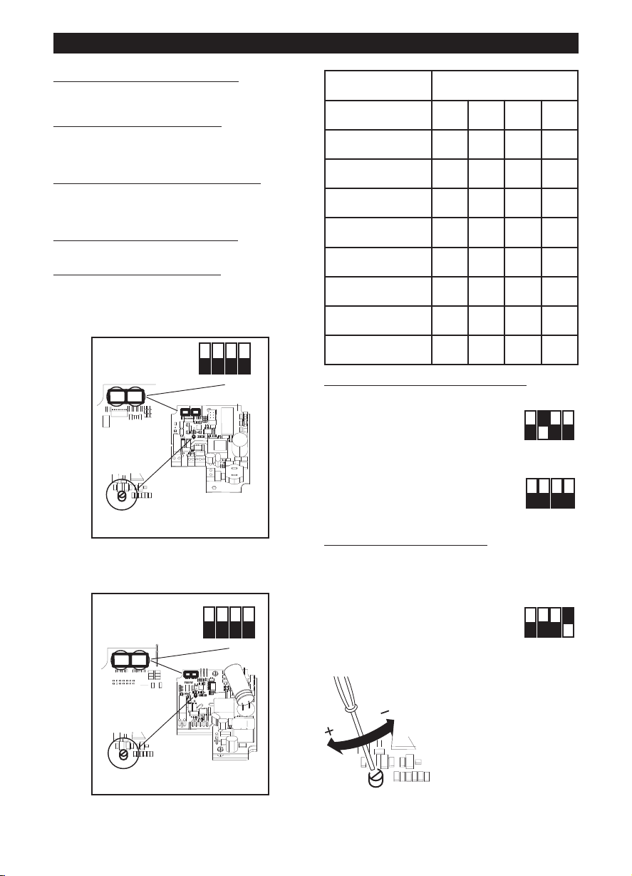
Configurazione iniziale
L’installatore deve configurare il funzionamento
dell’apparecchio seguendo i passi descritti più avanti.
Selezione del modello del prodotto
Questa fase è eseguita in fabbrica, le istruzioni
r
s
n seguito a manomissioni accidentali del dip switch.
i
Selezione della modalità di funzionamento
seguito. Sono previste due modalità: a due velocità
V1 e V2, selezionabili tramite interruttore esterno,
oppure con velocità regolabile tramite potenziometro
esterno.
Impostazione dei valori di V1 e V2
modalità di funzionamento a due velocità)
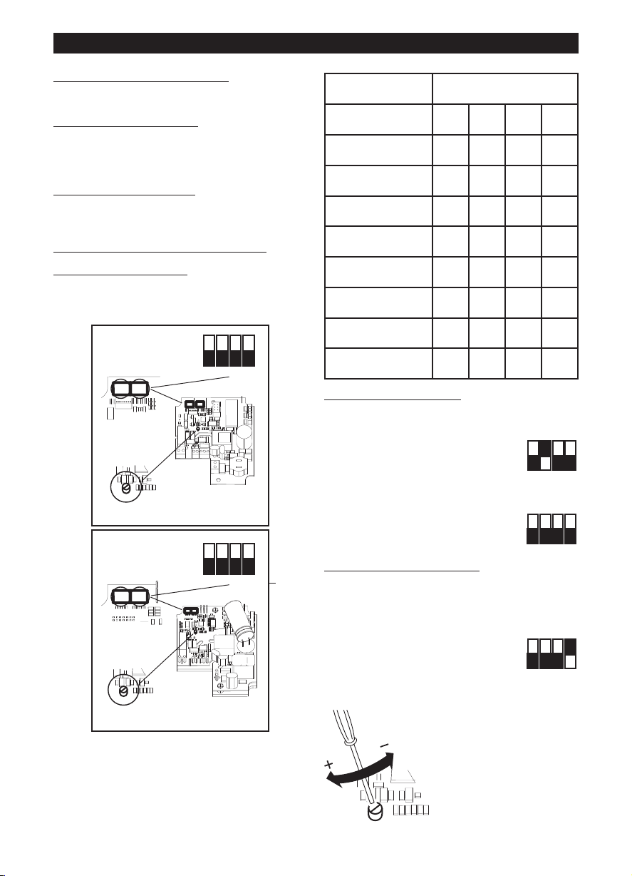
Selezione del modello del prodotto
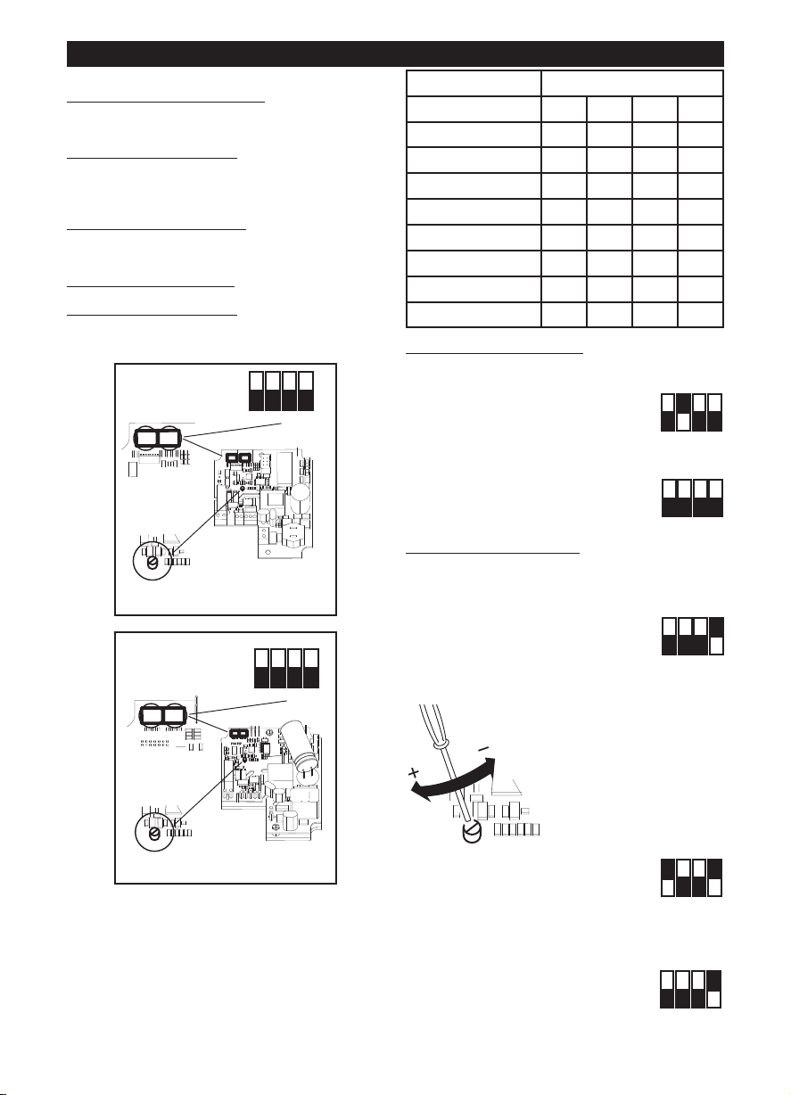
La selezione del modello si effettua tramite
l’impostazione del dip switch SW1 indicato in figura e
come descritto nella seguente tabella.
: vedi nel seguito.
iportate nel presente libretto possono essere utili
olo nel caso sia necessario ripristinare la situazione
: vedi nel
(nel caso di
LINEO 100 Q V0 ES - LINEO 200 V0 ES
LINEO 250 V0 ES, LINEO 315 V0 ES
Modello SW1
Int.1 Int.2 Int.3 Int.4
LINEO 100 Q V0 ES OFF OFF OFF OFF
LINEO 100 V0 ES OFF OFF OFF ON
LINEO 125 V0 ES OFF OFF ON OFF
LINEO 150 V0 ES OFF OFF ON ON
LINEO 160 V0 ES OFF ON OFF OFF
LINEO 200 V0 ES OFF ON OFF ON
LINEO 250 V0 ES OFF ON ON OFF
LINEO 315 V0 ES OFF ON ON ON
Selezione della modalità di funzionamento
Modalità a due velocità:
togliere l’alimentazione elettrica
impostare sul dip-switch SW2
indicato in figura:
Int.2=ON; Int.3=OFF
Int.4=OFF
Modalità a velocità regolabile:
togliere l’alimentazione elettrica
impostare sul dip-switch SW2
indicato in figura:
Int.2=OFF; Int.3=OFF
Int.4=OFF
Impostazione dei valori di V1 e V2
L’apparecchio esce dalla fabbrica con impostazioni
nominali di default V1=V
E’ possibile regolare i valori di V1 e V2 operando
come segue:
- togliere l’alimentazione elettrica
- impostare sul dip-switch SW2
indicato in figura:
Int.1=OFF
Int.4=ON
- fornire l’alimentazione elettrica. Il motore si porta
automaticamente alla velocità V1temp
, V2=V
MIN
MAX
- agire sul trimmer (vedi
figura) per regolare V1temp
sul valore desiderato,
compreso tra V1nom e la V2
memorizzata – 100Rpm
6
Page 7
ITALIANO
ON
1 2 3 4
OFF
ON
1 2 3 4
OFF
ON
1 2 3 4
OFF
ON
1 2 3 4
OFF
ON
1 2 3 4
OFF
- impostare Int.1=ON. Ciò produce
due effetti:
il valore V1temp viene
emorizzato come nuovo V1;
m
l motore si porta automaticamente alla V2temp
i
agire sul trimmer (vedi figura) per regolare V2temp
sul valore desiderato, compreso tra la V1
emorizzata + 100Rpm e Vmax
m
impostare Int.1=OFF. Ciò produce
-
ue effetti:
d
il valore V2temp viene
memorizzato come nuovo V2;
il motore si porta automaticamente alla V1temp
- togliere l’alimentazione elettrica
- impostare Int.4=OFF per bloccare
i valori di V1 e V2
Ripristino valori nominali
Qualora fosse necessario, è possibile ripristinare i
valori nominali di fabbrica di V1 e V2, attraverso la
seguente procedura:
- togliere l’alimentazione elettrica
- impostare sul dip-switch SW2
indicato in figura:
Int.3=ON
- fornire l’alimentazione elettrica:
V1 e V2 sono automaticamente ripristinati ai valori
nominali di fabbrica relativi al modello selezionato
come descritto sopra. L’avvenuto ripristino dei
valori nominali è segnalato con due lampeggi rapidi
di un LED presente a bordo della scheda; il motore
viene automaticamente disattivato
- togliere l’alimentazione elettrica
- ripristinare sul dip-switch SW2
indicato in figura:
Int.3=OFF
Funzionamento
A seconda della modalità scelta in fase di
installazione:
- modalità a due velocità: l’apparecchio ha
funzionamento in continuo; è possibile selezionare
due velocità V1 e V2 tramite interruttore esterno
- modalità a velocità regolabile: l’apparecchio può
funzionare a velocità regolabile, da 300 Rpm a
Vmax (tramite potenziometro esterno). Puo’ essere
utilizzata anche la scatola comandi Vortice ON/OFF
+ potenziometro (cod. 12826, a richiesta).
SMALTIMENTO
N ALCUNI PAESI DELL'UNIONE EUROPEA QUE-
I
TO PRODOTTO NON RICADE NEL CAMPO DI
S
PPLICAZIONE DELLA LEGGE NAZIONALE DI
A
RECEPIMENTO DELLA DIRETTIVA RAEE E
UINDI NON È IN ESSI VIGENTE ALCUN OB-
Q
LIGO DI RACCOLTA DIFFERENZIATA A FINE
B
ITA.
V
Attenzione
Questo prodotto è conforme alla Direttiva EU
2012/19/EC.
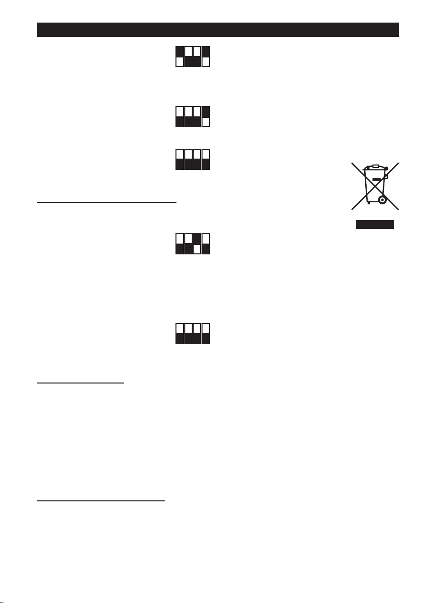
Il simbolo del cassonetto barrato
riportato sull’apparecchio indica che
il prodotto, alla fine della propria vita
utile, dovendo essere trattato
separatamente dai rifiuti domestici,
deve essere conferito in un centro di
raccolta differenziata per
apparecchiature elettriche ed
elettroniche oppure riconsegnato al
rivenditore al momento dell’acquisto di una nuova
apparecchiatura equivalente.
Presso i rivenditori di prodotti elettronici con
superficie di vendita di almeno 400 m
possibile consegnare gratuitamente, senza obbligo di
acquisto, i prodotti elettrici ed elettronici da smaltire,
se di dimensioni inferiori a 25 cm.
L’utente è responsabile del conferimento
dell’apparecchio a fine vita alle appropriate strutture
di raccolta, pena le sanzioni previste dalla vigente
legislazione sui rifiuti.
L’adeguata raccolta differenziata per l’avvio
successivo dell’apparecchio dismesso al riciclaggio,
al trattamento e allo smaltimento ambientalmente
compatibile contribuisce ad evitare possibili effetti
negativi sull’ambiente e sulla salute e favorisce il
riciclo dei materiali di cui è composto il prodotto.
Per informazioni più dettagliate inerenti i sistemi di
raccolta disponibili, rivolgersi al servizio locale di
smaltimento rifiuti, o al negozio in cui è stato
effettuato l’acquisto.
I produttori e gli importatori ottemperano alla loro
responsabilità per il riciclaggio, il trattamento e lo
smaltimento ambientalmente compatibile sia
direttamente sia partecipando ad un sistema
collettivo.
2
è inoltre
Manutenzione / Pulizia
Fig 27, 28, 29.
7
Page 8

ENGLISH
Attention:
this symbol indicates that care must be taken
to avoid injury to the user
!
Caution:
this symbol indicates that care must be taken
to avoid damaging the appliance
!
Description and operation
he appliance you have bought is a mixed-flow fan
T
for expelling air through ducting.
The appliance is made from self-extinguishing V0
thermoplastic resin and is protected against water
spray. It has an electronically controlled two-speed
rushless motor with maximum and minimum speed
b
ettings.
s
Safety
•Do not use this appliance for functions other than
those described in this booklet
• After removing the appliance from its packaging,
ensure that it is complete and undamaged. If in
doubt contact a professionally qualified electrician
or Vortice. Do not leave packaging within the reach
of children or infirm persons
• Certain fundamental rules must be observed when
using any electrical appliance, including:
-never touch electrical appliances with wet or
damp hands;
- never touch appliances while barefoot;
- never allow children or infirm persons to operate
appliances unattended.
• Store the appliance out of the reach of children and
differently able persons after deciding to disconnect
it from the power supply and use it no more.
• Do not us the appliance where flammable vapours
are present (spirit, insecticides, petrol, etc.).
• Do not make modifications of any kind to this
appliance.
• Do not expose this appliance to the weather (rain,
sun, etc.).
• Do not place objects on top of the appliance.
• Regularly inspect the appliance for visible defects. If
the appliance does not function correctly, do not
use it and contact Vortice immediately.
• If the appliance does not function correctly or
develops a fault, contact Vortice immediately and
ensure that only genuine original Vortice spares are
used for any repairs.
• Should the appliance be dropped or suffer a heavy
blow, have it checked immediately by Vortice
• The electrical power supply/socket to which the
appliance is to be connected must be able to
provide the maximum electrical power required by
the appliance
• Switch off the appliance at the installation's main
switch: a) if the appliance does not function
correctly; b) before cleaning the outside of the
appliance, c) if the appliance is not to be used for
any length of time.
• Ensure that the room has an adequate source of
fresh air to ensure correct appliance operation. In
the event that other non-sealed combustion-based
ppliances (such as water heater or gas stove) are
a
nstalled in the same room, check that air
i
eplacement is sufficient for all appliances to work
r
effectively together.
The appliance cannot be used to control activation
•
f water heaters, room heaters, etc. and it must not
o
xhaust into the hot air flues.
e
• Ensure that the appliance discharges into a single
duct (dedicated to this product).
• Do not cover or block appliance intake or outlet
vents grilles as this may prevent optimum air flow.
• The appliance inlets and outlets must always be
connected to ducting.
• The maximum environment temperature for
appliance operation is 60°C, with the exception of
models 250 and 315 for which it is instead 50°C.
• Protection from over-currents and overload is
guaranteed by the control electronics. Models from
100 to 250 are equipped with a thermal protection
fuse, while model 315 is equipped with a thermal
protection with manual reset. In the event that the
thermal fuse is triggered, repair or replace the
product after having checked and removed the
cause of the intervention. If the manual reset
protector is triggered, switch off the power supply
for half an hour and then restore the power supply
after having checked and removed the cause of the
intervention.
• Specifications for the power supply must
correspond to the electrical data on data plate A.
(Fig.A)
•This appliance can be used by
children aged from 8 years and
above and persons with
reduced physical, sensory or
mental capabilities or lack of
experience and knowledge if
they have been given
supervision or instruction
concerning use of the appliance
in a safe way and understand
the hazards involved. Children
shall not play with the
appliance. Cleaning and user
maintenance shall not be made
by children without supervision.
•These appliances are designed
for use in residential and
commercial properties.
•The appliance must be installed
by a professionally qualified
electrician.
•The electrical system to which
8
Page 9

ENGLISH
the product is connected must
be in compliance with
applicable regulations.
•An omnipolar switch with a
contact opening distance of 3
mm or higher should be
provided for installation,
enabling complete
disconnection under
overvoltage category III
conditions.
Products equipped with singlephase wiring (M) engines
ALWAYS require connection to
220-240V (or only 230V where
required) single-phase lines. Any
kind of modification shall be
considered as product tampering
and shall nullify the relative
warranty.
Duct and window - wall fan
units
Precautions must be taken to
prevent gas coming from the gas
flue pipe or from other fuel
combustion units from entering
into the room.
Typical application
Fig. 1-2;
If the appliance is installed at a height of less than 2.3
metres from ground level and the length of the
ucting connected to the inlet and outlet so requires,
d
pecial safety devices should be fitted to prevent any
s
isk of contact with the blades.
r
Installation
Fig. 3 ÷ 26;
Fig.3: E= Air flow direction data plate; C= Air Inlet; D=
Air Outlet.
Window - wall fan units
Fans have been designed to be
mounted on windows or external
walls.
Units equipped with manual
reset thermal breaker device
In order to avoid any danger of
accidental reset of the thermal
breaker device, units must not be
powered by an external switch
device such as a timer, or must
not be connected to a circuit that
is regularly powered or
disconnected from power utilities
9
Page 10
ON
1 2 3 4
OFF
ON
1 2 3 4
OFF
ON
1 2 3 4
OFF
ON
1 2 3 4
OFF
ON
1 2 3 4
O
FF
ON
1 2 3 4
OFF
ENGLISH
ON
1 2 3 4
OFF
DIPSWITCH
TRIMMER
12
SW 1 : MODEL
SW 2 : SETUP
ON
1 2 3 4
OFF
DIPSWITCH
12
SW 1 : MODEL
SW 2 : SETUP
TRIMMER
ON
1 2 3 4
OFF
Initial configuration
he installer must configure appliance operation by
T
following the steps described later on.
selecting the product model: see below. This step is
carried out in the factory; the instructions provided in
this booklet may only be of use if it becomes
ecessary to reset the status following accidental
n
ampering with the dip-switch.
t
electing the operating mode
s
two modes: with two speeds V1 and V2, which can
be selected via an external switch, or with speed that
can be adjusted via an external potentiometer.
setting the V1 and V2 values
mode)
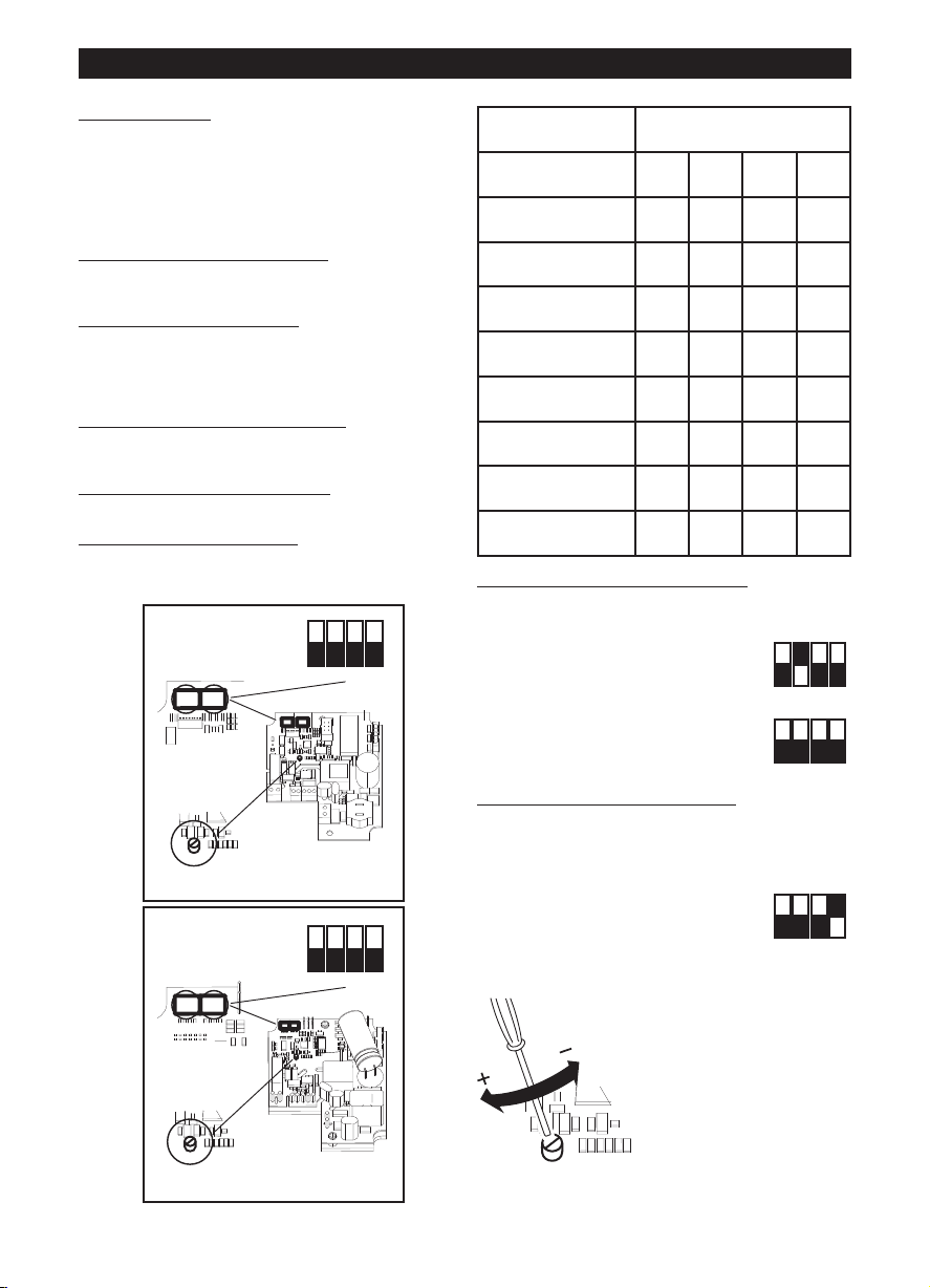
Selecting the product model
The model is selected by setting the dip-switch 1
indicated in the figure as described in the table below.
LINEO 100 Q V0 ES - LINEO 200 V0 ES
see below. There are
:
(for two-speed operating
Model SW1
Int.1 Int.2 Int.3 Int.4
LINEO 100 Q V0 ES OFF OFF OFF OFF
LINEO 100 V0 ES OFF OFF OFF ON
LINEO 125 V0 ES OFF OFF ON OFF
LINEO 150 V0 ES OFF OFF ON ON
LINEO 160 V0 ES OFF ON OFF OFF
LINEO 200 V0 ES OFF ON OFF ON
LINEO 250 V0 ES OFF ON ON OFF
LINEO 315 V0 ES OFF ON ON ON
Selecting the operating mode
Two-speed mode:
cut off the power supply
set the dip-switch SW2 indicated in
the figure:
Int.2=ON; Int.3=OFF
Int.4=OFF
Adjustable speed mode:
cut off the power supply
set the dip-switch SW2 indicated in
the figure:
Int.2=OFF; Int.3=OFF
Int.4=OFF
Setting the V1 and V2 values
The appliance leaves the factory with default nominal
settings V1=V
Values V1 and V2 can be adjusted as follows:
- cut off the power supply
- set the dip-switch SW2 indicated
in the figure:
Int.1=OFF
Int.4=ON
- restore the power supply. The motor automatically
runs at the V1temp speed
MIN
, V2=V
MAX
- use the trimmer (see
figure) to set V1temp to the
desired value, between
V1nom and the saved V2 –
100Rpm
LINEO 250 V0 ES, LINEO 315 V0 ES
- set Int.1=ON. This produces two
effects:
the V1temp value is saved as a
new V1;
the motor automatically runs at V2temp;
- use the trimmer (see figure) to set V2temp to the
desired value, between the saved V1 + 100Rpm and
Vmax;
- set Int.1=OFF. This produces two
effects: the V2temp value is saved
as a new V2;
the motor automatically runs at
10
Page 11
ENGLISH
ON
1 2 3 4
OFF
ON
1 2 3 4
OFF
ON
1 2 3 4
OFF
V1temp
- cut off the power supply
- set Int.4=OFF to lock the V1 and
2 values
V
Restoring nominal values
f necessary, the nominal factory-set values for V1
I
nd V2 can be restored using the following
a
procedure:
- cut off the power supply
- set the dip-switch SW2 indicated
in the figure:
Int.3=ON
- restore the power supply:
V1 and V2 are automatically restored to the nominal
factory-set values corresponding to the selected
model, as described above. The restoring of
nominal values is indicated by two quick flashes of
an LED on the card.
The motor is deactivated automatically
- cut off the power supply
- reset the dip-switch SW2
indicated in the figure:
Int.3=OFF
Operation
Depending on the mode selected during installation:
- two-speed mode: the appliance operates
continuously; two speeds V1 and V2 can be
selected using an external switch
- adjustable speed mode: the appliance can operate
at a speed which is adjusted between 300 Rpm and
Vmax (via an external potentiometer). The Vortice
ON/OFF control box + potentiometer (code 12826,
on request) can also be used.
Maintenance / Cleaning
Fig. 27, 28, 29.
DISPOSAL
N CERTAIN EUROPEAN UNION COUNTRIES THIS
I
PRODUCT DOES NOT FALL WITHIN THE
EQUIREMENTS OF THE NATIONAL LAWS
R
IMPLEMENTING THE WEEE DIRECTIVE, AND IN
HESE COUNTRIES THE PRODUCT IS NOT
T
SUBJECT TO SEPARATE DISPOSAL OPERATIONS
AT THE END OF ITS WORKING LIFE.
Important
This product conforms to EU Directive EU
2012/19/EC.
This appliance bears the symbol of
the barred waste bin. This indicates
that, at the end of its useful life, it
must not be disposed of as domestic
waste, but must be taken to a
collection centre for waste electrical
and electronic equipment, or returned
to a retailer on purchase of a
replacement.
It is the user's responsibility to dispose of this
appliance through the appropriate channels at the
end of its useful life. Failure to do so may incur the
penalties established by laws governing waste
disposal.
Proper differential collection, and the subsequent
recycling, processing and environmentally
compatible disposal of waste equipment avoids
unnecessary damage to the environment and
possible related health risks, and also promotes
recycling of the materials used in the appliance.
For further information on waste collection and
disposal, contact your local waste disposal service,
or the shop from which you purchased the appliance.
Manufacturers and importers fulfil their responsibilities
for recycling, processing and environmentally
compatible disposal either directly or by participating
in collective systems.
11
Page 12

FRANCAIS
Attention:
ce symbole indique la nécessité de prendre
quelques précautions pour la sécurité
de l’utilisateur
!
Avertissement:
ce symbole indique la nécessité de prendre
quelques précautions pour la sécurité
du produit
!
Description et mode d’employ
'appareil que vous venez d'acheter est un aérateur
L
hélico-centrifuge de conduit servant à rejeter l'air
dans un conduit de ventilation.
L'appareil en résine thermoplastique auto-extinguible
V0 est protégé contre les projections d'eau. Il est
quipé d'un moteur brushless à deux vitesses à
é
ommande électronique avec possibilité de réglage
c
es valeurs de petite et grande vitesse.
d
Sécurité
• Ne pas utiliser l'appareil pour un usage autre que
celui décrit dans ce livret
• Contrôler l'intégrité de l'appareil après l'avoir sorti
de son emballage : dans le doute, s'adresser
immédiatement à une personne
professionnellement qualifiée ou à un Service
après-vente agréé Vortice. Placer les éléments de
l'emballage hors de la portée des enfants ou des
personnes inexpertes.
• L'utilisation de tout appareil électrique implique le
respect de quelques règles fondamentales dont,
entre autres :
- ne pas toucher l'appareil avec des mains
mouillées ou humides;
- ne pas toucher l'appareil pieds nus;
- interdire son utilisation aux enfants ou aux
personnes inexpertes.
• Ranger l'appareil hors de portée des enfants et des
personnes inexpertes après l'avoir débranché du
réseau électrique pour ne plus l'utiliser.
• Ne pas utiliser l'appareil en présence de substances
ou de vapeurs inflammables telles que alcool,
insecticides, essence, explosifs etc.
prise est adaptée à la puissance maximale de
l'appareil. Dans le cas contraire, s'adresser
immédiatement à des professionnels qualifiés
Couper l'interrupteur général de l'installation dans
•
es cas suivants : a) dysfonctionnement ; b) pour
l
rocéder à un nettoyage extérieur ; c) lorsque
p
l'appareil n'est pas utilisé pendant une longue
ériode.
p
Il est indispensable d’assurer une arrivée d’air
•
déquate dans la pièce pour garantir le
a
fonctionnement de l’appareil.Si dans la pièce à
ventiler, un autre appareil à combustion (tel
quechauffe-eau, radiateur à gaz, etc.) est installé et
qu’il n’est pas étanche, il faut s’assurer que le
renouvellement d’air est adéquat pour garantir le
fonctionnement conjoint des appareils.
• L'appareil ne peut être utilisé comme activateur de
chauffe-eau, poêle etc. et il ne doit pas expulser
dans les conduits d'air chaud de ces appareils.
• L'appareil doit expulser l'air dans un conduit lui
étant exclusivement réservé.
• Ne pas couvrir ni obstruer les deux grilles
d'aspiration et de refoulement de l'appareil pour
assurer le passage optimal de l'air.
• La bouche d’extraction et de refoulement de
l’appareil doit toujours être raccordée à un conduit.
• La température ambiante maximum pour le
fonctionnement de l'appareil est de 60°C, exception
faite pour les modèles 250 et 315 pour lesquels elle
est de 50°C.
• La protection contre les surchauffes et la surcharge
est garantie par la commande électronique. Les
modèles du 100 au 250 sont équipés de fusible
thermique de protection, alors que le modèle 315
est doté de protecteur thermique à réarmement
manuel. En cas d'intervention du fusible thermique,
réparer ou remplacer le produit après avoir vérifié et
solutionné la cause de son intervention. En cas
d'intervention du limiteur à réarmement manuel,
couper le courant pendant une demi-heure puis le
rétablir après avoir vérifié et solutionné la cause de
son intervention.
• Les données électriques du réseau doivent
correspondre à celles inscrites sur la plaque A.
(Fig.A)
• Ne modifier l'appareil en aucune façon.
• Ne pas exposer l'appareil aux agents
atmosphériques (pluie, soleil etc).
• Ne rien poser sur l’appareil.
• Contrôler périodiquement, de visu, l'intégrité de
l'appareil. En cas de défectuosité, ne pas utiliser
l'appareil et contacter immédiatement un Service
après-vente agréé Vortice.
• En cas de dysfonctionnement et/ou de panne,
s'adresser immédiatement à un Service aprèsvente agréé Vortice et exiger, en cas de réparation,
l'emploi de pièces détachées originales Vortice.
• Si l'appareil tombe ou reçoit des coups violents, le
faire vérifier immédiatement auprès d'un Service
après-vente agréé Vortice
• Brancher l'appareil au réseau d'alimentation/à la
prise électrique si la puissance de l'installation/de la
12
•Cet appareil peut être utilisé par
des enfants âgés de plus de 8
ans et des personnes porteuses
d'un handicap physique,
sensoriel ou mental, ou encore
sans expériences ou
connaissances spécifiques, à
condition de travailler sous
supervision ou après avoir reçu
les instructions d'utilisation de
l'appareil en toute sécurité, et
après en avoir parfaitement
compris les dangers. Les
enfants ne doivent pas jouer
Page 13

FRANCAIS
avec l'appareil. Le nettoyage et
l'entretien réservés à l'utilisateur
ne doivent pas être effectués
par des enfants sans
surveillance.
•Ces appareils ont été conçus
pour un usage domestique et
commercial.
•L'installation de l'appareil est
réservée à des techniciens
qualifiés.
•L’installation électrique à
laquelle le produit est raccordé
doit être conforme aux normes
en vigueur.
•Pour l'installation, prévoir un
interrupteur unipolaire ayant une
distance d'ouverture des
contacts égale ou supérieure à 3
mm, qui permette la
déconnexion complète dans les
conditions de catégorie de
surtension III.
•Les produits équipés de
moteurs prédisposés au
câblage monophasé (M)
nécessitent TOUJOURS d'une
connexion à des lignes
monophasées à 220-240 V (ou
seulement 230 V quand le
produit le prévoit). Toute sorte
de modification est considérée
comme une manipulation du
produit et annule la garantie
correspondante.
extérieurs.
Appareils équipés d'un
thermostat de sûreté à
réarmement manuel
Afin d'éviter tout danger dû au
réarmement manuel du
thermostat de sûreté, cet
appareil ne doit pas être
alimenté avec un thermostat
externe, tel qu'un temporisateur
ou ne doit pas être raccordé à
un circuit qui est régulièrement
alimenté ou déconnecté du
service.
Applications typiques
Figg. 1-2;
Lorsque l'appareil est installé à une hauteur inférieure
à 2,3 m du sol et la longueur des tuyaux reliés en
extraction et refoulement le requiert, il est opportun
de monter des dispositifs visant à prévenir le risque
de contacts avec l'hélice.
Ventilateurs pour conduit et
fenêtre - mur
Il est nécessaire de prendre ses
précautions afin d'éviter des
émanations de gaz provenant du
conduit d'évacuation des gaz ou
d'autres appareils à combustion
de carburant.
Ventilateurs pour fenêtre - mur
Le ventilateur doit être monté
sur des fenêtres ou sur des murs
13
Page 14
FRANCAIS
ON
1 2 3 4
OFF
DIPSWITCH
TRIMMER
12
SW 1 : MODEL
SW 2 : SETUP
ON
1 2 3 4
OFF
DIPSWITCH
12
SW 1 : MODEL
SW 2 : SETUP
TRIMMER
ON
1 2 3 4
OFF
ON
1 2 3 4
OFF
ON
1 2 3 4
OFF
Installation
F
Fig.3: E= Plaquette de direction du débit d’air; C=
Aspiration; D= Refoulement;
Configuration initiale
L'installateur doit configurer l'appareil en suivant les
étapes décrites ci-après.
sélection du modèle d'appareil
phase est réalisée en usine. Les instructions
présentes dans la notice peuvent être utiles
uniquement s'il s'avère nécessaire de rétablir la
situation au cas où le dip-switch aurait été
endommagé.
sélection du mode de fonctionnement
Deux modes sont prévus : à deux vitesses V1 et V2,
à sélectionner à travers l'interrupteur extérieur, ou à
vitesse réglable via potentiomètre extérieur.
programmation des valeurs V1 et V2
fonctionnement à deux vitesses)
Sélection du modèle d'appareil
Sélectionner le modèle en configurant le dip-switch
indiqué sur la figure et en suivant les descriptions
dans le tableau suivant.
ig. 3 ÷ 26;
: voir ci-après. Cette
: voir ci-après.
(pour le mode de
LINEO 100 Q V0 ES - LINEO 200 V0 ES
Model SW1
Int.1 Int.2 Int.3 Int.4
LINEO 100 Q V0 ES OFF OFF OFF OFF
LINEO 100 V0 ES OFF OFF OFF ON
LINEO 125 V0 ES OFF OFF ON OFF
LINEO 150 V0 ES OFF OFF ON ON
LINEO 160 V0 ES OFF ON OFF OFF
LINEO 200 V0 ES OFF ON OFF ON
LINEO 250 V0 ES OFF ON ON OFF
LINEO 315 V0 ES OFF ON ON ON
Sélection du mode de fonctionnement
Mode à deux vitesses :
mettre l'appareil hors tension
configurer, sur le dip-switch SW2 indiqué sur la figure :
Int.2=ON; Int.3=OFF
Int.4=OFF
Mode à vitesse réglable :
mettre l'appareil hors tension
configurer, sur le dip-switch SW2
indiqué sur la figure :
Int.2=OFF; Int.3=OFF
Int.4=OFF
Programmation des valeurs V1 et V2
L'appareil quitte l'usine avec des valeurs nominales
par défaut V1=V
Il est possible de régler les valeurs V1 et V2 en
procédant de la façon suivante :
- mettre l'appareil hors tension
- configurer, sur le dip-switch SW2
indiqué sur la figure:
Int.1=OFF
Int.4=ON
- remettre l'appareil sous tension. Le moteur tourne
automatiquement à la vitesse V1temp
, V2=V
MIN
MAX
-- tourner le trimmer (voir
figure) pour régler V1temp
sur une valeur au choix,
comprise entre V1nom et la
V2 mémorisée – 100Rpm
LINEO 250 V0 ES, LINEO 315 V0 ES
14
- programmer Int.1=ON. Ceci produit deux effets:
la valeur V1temp est mémorisée comme nouvelle
Page 15
FRANCAIS
ON
1 2 3 4
OFF
ON
1 2 3 4
OFF
ON
1
2 3 4
OFF
ON
1 2 3 4
OFF
ON
1 2 3 4
OFF
valeur V1
e moteur tourne
l
automatiquement à la vitesse
V2temp
tourner le trimmer (voir figure) pour régler V2temp
sur une valeur au choix, comprise entre V1
émorisée + 100 et Vmax
m
- programmer Int.1=OFF. Ceci
roduit deux effets :
p
la valeur V2temp est mémorisée
omme nouvelle valeur V2
c
le moteur tourne automatiquement à la vitesse
V1temp
- mettre l'appareil hors tension
- programmer Int.4=OFF pour
bloquer les valeurs V1 et V2
Rétablissement des valeurs
nominales
Si nécessaire, il est possible de rétablir les valeurs
nominales d'usine pour V1 et V2 à travers la
procédure suivante :
- mettre l'appareil hors tension
- configurer, sur le dip-switch SW2
indiqué sur la figure :
Int.3=ON
- remettre l'appareil sous tension:
V1 et V2 sont automatiquement rétablies aux
valeurs nominales par défaut en fonction du modèle
sélectionné, comme décrit ci-dessus. Lorsque les
valeurs nominales sont rétablies, une led
embarquée sur la carte clignote rapidement pour
signaler l'opération.
Le moteur est automatiquement désactivé.
- mettre l'appareil hors tension
- rétablir, sur le dip-switch SW2
indiqué sur la figure:
Int.3=OFF
Fonctionnement
Le fonctionnement dépend du mode choisi en phase
d'installation :
- mode à deux vitesses : l’appareil fonctionne en
mode continu ; possibilité de sélectionner deux
vitesses V1 et V2 à travers l'interrupteur extérieur
- mode à vitesse réglable : l'appareil peut fonctionner
à vitesse réglable, de 300 Rpm à Vmax (via
potentiomètre extérieur). Possibilité d'utiliser
également le boîtier de commandes Vortice
ON/OFF + potentiomètre (réf. 12826, sur demande).
ÉLIMINATION
DANS CERTAINS PAYS DE L'UNION
EUROPÉENNE, CE PRODUIT NE FAIT PAS PARTIE
U DOMAINE D'APPLICATION DE LA LOI
D
ATIONALE D'ASSIMILATION DE LA DIRECTIVE
N
DEEE ET PAR CONSÉQUENT, IL N'Y EXISTE
UCUNE OBLIGATION DE COLLECTE
A
DIFFÉRENCIÉE À LA FIN DE SA DURÉE DE VIE.
Attention
Ce produit est conforme à la directive EU 2012/19/EC.
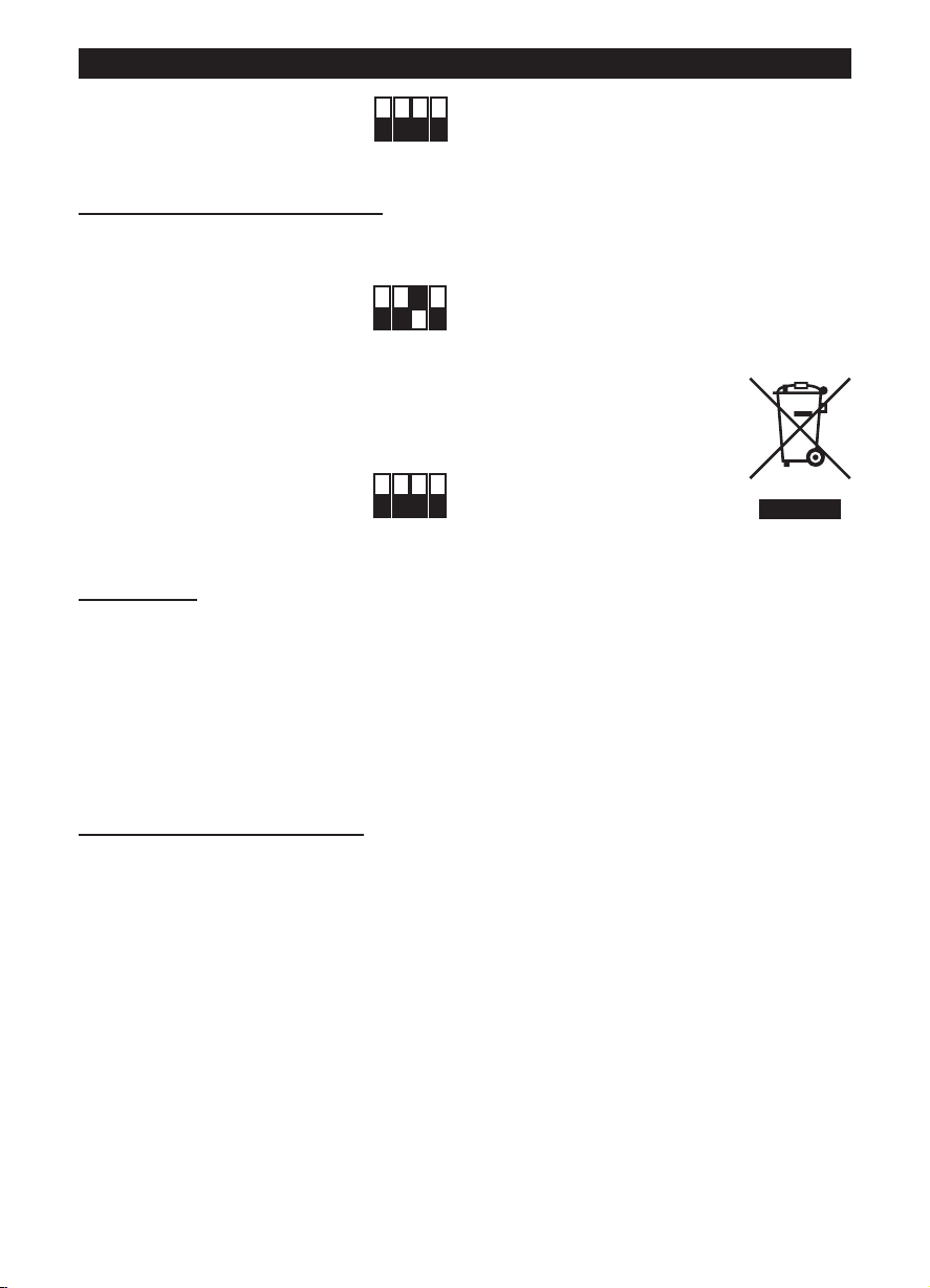
Le symbole représentant une
poubelle barrée présent sur l'appareil
indique qu'à la fin de son cycle de vie,
il devra être traité séparément des
déchets domestiques.
Il devra donc être confié à un centre
de collecte sélective pour appareils
électriques et électroniques ou
rapporté au revendeur lors de l'achat
d'un nouvel appareil.
La collecte sélective réalisée avant le recyclage, le
traitement et l'élimination compatible avec
l'environnement de l'appareil usagé contribue à éviter
les nuisances pour l'environnement et pour la santé
et favorise le recyclage des matériaux qui composent
le produit.
Proper differential collection, and the subsequent
recycling, processing and environmentally
compatible disposal of waste equipment avoids
unnecessary damage to the environment and
possible related health risks, and also promotes
recycling of the materials used in the appliance.
Pour de plus amples informations concernant les
systèmes de collecte existants, adressez-vous au
service local d'élimination des déchets ou au
magasin qui vous a vendu l'appareil.
Les fabricants et les importateurs optempèrent à leur
responsabilité en matière de recyclage, de traitement
et d'élimination des déchets compatible avec
l'environnement directement ou par l'intermédiaire
d'un système collectif.
Entretien / nettoyage
Fig. 27, 28, 29.
15
Page 16
DEUTSCH
Achtung:
dieses Symbol zeigt Vorsichtsmaßnahmen an
um Schäden am Bediener zu vermeiden
!
Hinweis:
dieses Symbol zeigt Vorsichtsmaßnahmen an
um Schäden am Gerät zu vermeiden
!
Beschreibung und Gebrauch
ei dem von Ihnen erworbenen Gerät handelt es sich
B
um einen Mischströmung-Rohrlüfter zum Absaugen
der Luft über ein Entlüftungsrohr.
Das Gerät ist aus selbstverlöschendem,
thermoplastischem Harz V0 gefertigt,
pritzwassergeschützt, und hat einen elektronisch
s
esteuerten, bürstenlosen Motor mit zwei
g
eschwindigkeitsstufen und verstellbarer Mindest-
G
und Höchstgeschwindigkeit.
Sicherheit
• Dieses Gerät darf nur für den in dieser Anleitung
angegebenen Verwendungszweck eingesetzt
werden.
• Das Gerät nach dem Auspacken auf
Transportschäden oder andere Mängel
untersuchen; im Zweifelsfall unverzüglich einen
Vortice-Vertragshändler verständigen. Das
Verpackungsmaterial nicht in Reichweite von
Kindern oder Personen lassen, die sich damit
schaden könnten.
• Beim Einsatz von Elektrogeräten jeder Art müssen
einige Grundregeln stets beachtet werden, wie
unter anderem:
- Das Gerät nicht mit nassen oder feuchten Händen
berühren;
- Nicht barfuß berühren;
- Nicht unbeaufsichtigt von Kindern oder Personen,
die sich damit schaden könnten, benutzen
lassen.
• Wird das Gerät nicht mehr benutzt, muss es vom
Stromnetz getrennt und außerhalb der Reichweite
von Kindern und Personen, die es allein nicht
sachgemäß bedienen können, aufbewahrt werden.
• Das Gerät nicht in der Nähe entflammbarer
Substanzen oder Dämpfe wie Alkohol, Insektizide,
Benzin usw. verwenden.
• Das Produkt nur dann an das Stromnetz
nschließen, wenn die Stromfestigkeit der
a
Anlage/Steckdose für die maximale Leistung
geeignet ist. Sollte dies nicht der Fall sein, sofort
ualifiziertes Fachpersonal beiziehen
q
• Schalten Sie den Hauptschalter aus, wenn: a) eine
etriebsstörung festgestellt wird. b) das
B
Geräteäußere gereinigt werden muss. c) das Gerät
ängere Zeit nicht benutzt wird.
l
• Es muss gewährleistet sein, dass genügend Luft in
en Raum nachströmen kann, damit das Gerät
d
einwandfrei funktioniert. Wenn im selben Raum eine
mit Brennstoff betriebene Heizvorrichtung (z.B.
Durchlauferhitzer, Methangasofen o.ä.) installiert ist,
die zur Raumluft nicht abgedichtet ist, muss dafür
gesorgt werden, dass die nachströmende Luft auch
für den einwandfreien Verbrennungsablauf dieser
Vorrichtung ausreicht.
• Das Gerät darf nicht als Aktivator für Heizlüfter,
Öfen usw. benutzt werden. Die Abluft darf nicht in
Warmluftleitungen geleitet werden.
• Die Abluft des Gerätes muss in einen separaten
Kanal (der ausschließlich von diesem Gerät genutzt
wird) geleitet werden.
• Die beiden Ansaug- und Auslassgitter des Gerätes
stets freihalten, damit ein optimaler Luftdurchgang
gewährleistet wird.
• Der Zu- und der Abluftstutzen des Gerätes müssen
immer an eine Rohrleitung angeschlossen sein
• Die maximale Umgebungstemperatur für den
Gerätebetrieb ist 60 °C, ausgenommen die Modelle
250 und 315 mit einer Höchsttemperatur von 50 °C.
• Der Überhitze- und Überlastungsschutz wird durch
die Steuerelektronik gesichert. Die Modelle von 100
bis 250 sind mit Schmelzsicherungen ausgestattet,
während das Modell 315 mit einer
Wärmeschutzvorrichtung mit manueller
Rückstellung versehen ist. Beim Ansprechen der
Schmelzsicherung, das Produkt reparieren oder
auswechseln, nachdem die Ursache für das
Ansprechen festgestellt und behoben ist. Bei einem
Ansprechen des Temperaturbegrenzer mit
manueller Rückstellung die Versorgungsspannung
für eine halbe Stunden unterbrechen, nachdem die
Ursache für das Ansprechen festgestellt und
behoben ist.
• Die elektrischen Daten der Netzversorgung müssen
den Angaben auf dem Typenschild A entsprechen
(Abb. A).
• Keine Änderungen am Gerät anbringen.
• Das Gerät keinen Witterungseinflüssen (Regen,
Sonneneinstrahlung usw.) aussetzen.
• Keine Gegenstände auf dem Gerät ablegen.
• Regelmäßig den einwandfreien Zustand des
Gerätes überprüfen. Bei festgestellten Mängeln das
Gerät nicht benutzen und sofort einen VorticeVertragshändler verständigen.
• Bei Betriebsstörungen und/oder defektem Gerät
sofort einen Vortice-Vertragshändler aufsuchen und
für eine eventuelle Reparatur die Verwendung von
Vortice-Originalersatzteilen verlangen.
• Fällt das Gerät hin oder wurde es starken Stößen
ausgesetzt, muss es sofort von einem VorticeVertragshändler überprüft werden.
•Dieses Gerät darf von Kindern
ab 8 Jahren oder Personen mit
eingeschränkten körperlichen,
sensorischen oder geistigen
Fähigkeiten oder mangelnder
Erfahrung bzw. Kenntnis im
Umgang mit Elektrogeräten nur
unter der Aufsicht oder nach
gründlicher Unterweisung und
Überprüfung seitens einer für
ihre Sicherheit verantwortlichen
Person bedient werden. Kinder
dürfen nicht mit dem Gerät
16
Page 17

DEUTSCH
spielen. Die durch den
Anwender auszuführende
Reinigung und Pflege des
Geräts darf nicht von
unbeaufsichtigten Kindern
ausgeführt werden.
•Diese Geräte sind zur
Verwendung im Haushalt und in
gewerblichen Bereichen
ausgelegt.
•Die Elektroanlage, an die das
Produkt angeschlossen ist,
muss den geltenden
Vorschriften entsprechen.
•Für die Installation muss ein
mehrpoliger Stecker angebracht
sein, dessen Öffnungsabstand
der Kontakte gleich oder über 3
mm ist, mit dem die vollständige
Trennung unter Bedingungen
der Überspannungskategorie III
möglich ist.
•Die Produkte mit EinphasenMotoren (M) müssen STETS an
ein 220-240V (bzw. nur 230V,
sofern vorgesehen)
Einphasennetz angeschlossen
werden. Jede Änderung gilt als
unsachgemäßer Zugriff auf das
Produkt und macht die Garantie
ungültig.
Geräte mit thermischer
Trennvorrichtung und
manuellem Reset
Zum Vermeiden jeglicher
Gefahren durch das
versehentliche Zurücksetzen der
thermischen Trennvorrichtung
darf dieses Gerät weder über ein
externes Steuergerät wie eine
Zeitschaltuhr noch an einen
Schaltkreis angeschlossen
werden, der regulär mit Strom
versorgt wird oder von der
Stromversorgung getrennt ist.
Typische Anwendungsarten
Abb. 1-2;
Wird das Gerät tiefer als 2,3 m über dem Boden
installiert, und sind die Zu- bzw. Ableitungen relativ
kurz, müssen geeignete Schutzvorrichtungen
montiert werden, die einen direkten Kontakt mit dem
Läufer verhindern
Einstellung
Abb. 3 ÷ 26
Abb.3: E = Anzeige der Luftströmungsrichtung;
C=Ansaugung; D= Auslass;
Rohr- und Fensterventilatoren zur Wandmontage
Es müssen
S i ch e r h e i t sv or k e h r u ng en
ergriffen werden, die verhindern,
dass Gas aus dem
Rauchgaskanal oder anderen
Geräten, die Kraftstoff
verbrennen, in den Raum
zurückströmt.
Fensterventilatoren - zur
Wandmontage
Der Ventilator ist für die Montage
an Fenstern oder Außenwänden
bestimmt.
17
Page 18
DEUTSCH
ON
1 2 3 4
O
FF
ON
1 2 3 4
OFF
ON
1 2 3 4
OFF
DIPSWITCH
TRIMMER
12
SW 1 : MODEL
SW 2 : SETUP
ON
1 2 3 4
OFF
DIPSWITCH
12
SW 1 : MODEL
SW 2 : SETUP
TRIMMER
ON
1 2 3 4
OFF
ON
1 2 3 4
OFF
ON
1 2 3 4
OFF
Anfangskonfiguration
D
nachstehend beschrieben konfigurieren.
Auswahl des Gerätemodells: siehe unten. Diese
Phase wird im Werk durchgeführt, die in dieser
Betriebsanleitung enthaltenen Beschreibungen sind
n
w
S
Auswahl des Betriebsmodus
zwei Betriebsmodi: mit zwei, über einen externen
Schalter auswählbaren Drehzahlstufen V1 und V2
oder mit über ein externes Potentiometer
verstellbarer Drehzahl.
Einstellung der Werte V1 und V2
Betriebsmodus mit zwei Drehzahlstufen)
Auswahl des Gerätemodells
Die Auswahl des Gerätemodells erfolgt durch
Konfiguration des abgebildeten DIP-Schalters und
wie in der nachstehenden Tabelle beschrieben.
er Installateur muss den Betrieb des Geräts wie
ur nützlich, wenn die ursprüngliche Situation
iederhergestellt werden muss, nachdem die DIP-
chalter versehentlich verstellt wurden.
: siehe unten. Es gibt
(beim
LINEO 100 Q V0 ES - LINEO 200 V0 ES
LINEO 250 V0 ES, LINEO 315 V0 ES
Model SW1
Int.1 Int.2 Int.3 Int.4
LINEO 100 Q V0 ES OFF OFF OFF OFF
LINEO 100 V0 ES OFF OFF OFF ON
LINEO 125 V0 ES OFF OFF ON OFF
LINEO 150 V0 ES OFF OFF ON ON
LINEO 160 V0 ES OFF ON OFF OFF
LINEO 200 V0 ES OFF ON OFF ON
LINEO 250 V0 ES OFF ON ON OFF
LINEO 315 V0 ES OFF ON ON ON
Auswahl des Betriebsmodus
Betriebsmodus mit zwei Drehzahlstufen:
Die Stromversorgung trennen
Den abgebildeten DIP-Schalter SW2 wie folgt
einstellen:
Int.2=ON; Int.3=OFF
Int.4=OFF
Betriebsmodus mit regelbarer
Drehzahl:
Die Stromversorgung trennen
Den abgebildeten DIP-Schalter SW2
wie folgt einstellen:
Int.2=OFF; Int.3=OFF
Int.4=OFF
Einstellung der Werte V1 und V2
Werkseitig wird das Gerät auf die Defaultwerte
V1=V
Die Werte V1 und V2 können wie folgt eingestellt
werden:
- Die Stromversorgung trennen
- Den abgebildeten DIP-Schalter
- Die Stromversorgung wieder
, V2=V
MIN
SW2 wie folgt einstellen:
Int.1=OFF
Int.4=ON
herstellen. Der Motor wird automatisch auf die
Drehzahl V1temp gebracht
MAX
- Den Trimmer (siehe
Abbildung) verstellen, um
V1temp auf den
gewünschten Wert
zwischen V1nom und dem
gespeicherten V2 - 100Rpm
einzustellen
18
Page 19

ON
1 2 3 4
OFF
ON
1 2 3 4
OFF
ON
1 2 3 4
OFF
DEUTSCH
ON
1 2 3 4
OFF
ON
1 2 3 4
OFF
Int.1=ON einstellen. Diese
Einstellung hat zweierlei
uswirkungen:
A
er Wert V1temp wird als neuer
D
ert V1 gespeichert
W
er Motor wird automatisch auf die Drehzahl
D
2temp gebracht
V
Den Trimmer (siehe Abbildung) verstellen, um
-
2temp auf den gewünschten Wert zwischen dem
V
espeicherten V1 + 100Rpm und Vmax einzustellen
g
Int.1=OFF einstellen. Diese
Einstellung hat zweierlei
Auswirkungen:
Der Wert V2temp wird als neuer
Wert V2 gespeichert
Der Motor wird automatisch auf die Drehzahl
V1temp gebracht
- Die Stromversorgung trennen
- Int.4=OFF einstellen, um die
erte V1 und V2 zu blockieren
Wiederherstellen der
Nennwerte
Falls erforderlich, können die werkseitigen Nennwerte
V1 und V2 wie folgt wieder hergestellt werden:
- de Stromversorgung trennen
- den abgebildeten DIP-Schalter
SW2 wie folgt einstellen:
Int.3=ON
- Die Stromversorgung wieder
herstellen:
- V1 und V2 werden automatisch wieder auf die
werkseitigen Nennwerte des wie oben beschrieben
ausgewählten Modells zurückgesetzt. Die erfolgte
Wiederherstellung der Nennwerte wird von zwei
schnellen Blinkimpulsen einer LED an der Platine
angezeigt. Der Motor wird automatisch deaktiviert
- Die Stromversorgung trennen
- Den abgebildeten DIP-Schalter
SW2 wieder zurücksetzen:
Int.3=OFF
Betrieb
Abhängig von dem während der Installation
gewählten Betriebsmodus:
- Betriebsmodus mit zwei Drehzahlstufen: das Gerät
hat Dauerbetrieb; mit einem externen Schalter
können zwei Drehzahlstufen V1 und V2 gewählt
werden
- Betriebsmodus mit regelbarer Drehzahl: das Gerät
kann mit regelbarer Drehzahl von 300 Rpm bis
Vmax betrieben werden (mit über ein externes
Potentiometer ) Es kann auch der VorticeSchaltkasten ON/OFF + Potentiometer verwendet
werden (Code 12826, auf Anfrage).
ENTSORGUNG
IN EINIGEN EU-LÄNDERN GELTEN FÜR DIESES
RODUKT NICHT DIE VORGABEN DER
P
EUROPÄISCHEN RICHTLINIE ÜBER ELEKTRO-
ND ELEKTRONIK-ALTGERÄTE (WEEE-
U
RICHTLINIE) UND DEMNACH BESTEHT IN DIESEN
ÄNDERN AUCH KEINE PFLICHT FÜR DIE
L
MÜLLTRENNUNG BEI DER ENTSORGUNG DES
ERÄTES.
G
Attention
Dieses Gerät entspricht der EG-Richtlinie 2012/19/EC.
Das Symbol mit der
durchgestrichenen Abfalltonne am
Gerät bedeutet, dass das Gerät nach
seiner Aussonderung nicht im
Haushaltsmüll entsorgt werden darf,
sondern an einer Sammelstelle für
Elektro- und Elektronikgeräte oder
beim Kauf eines gleichwertigen
Neugerätes beim Händler abzugeben
ist.
Der Benutzer hat Sorge zu tragen, dass das Gerät
nach seiner Aussonderung an einer geeigneten
Sammelstelle abgegeben wird. Ein Nichtbeachten
dieser Vorschrift ist gemäß der geltenden
Abfallordnung strafbar.
Das geeignete Sortieren von Abfall und nachfolgende
Recyceln des aussortierten Gerätes zur
umweltverträglichen Entsorgung trägt zum Schutz
von Umwelt und Gesundheit bei und dient der
Wiederverwendung der recyclingfähigen Materialien,
aus denen das Gerät besteht.
Für detailliertere Informationen bezüglich der
verfügbaren Sammelsysteme wenden Sie sich an Ihre
örtliche Behörde oder an den Händler, bei dem Sie
das Gerät gekauft haben.
Die Hersteller und Importeure kommen ihrer
Verpflichtung zum umweltfreundlichen Recycling,
Verarbeiten und Entsorgen sowohl direkt als auch
durch Teilnahme an einem Kollektivsystem nach
Wartung / Reinigung
Abb. 27, 28, 29.
19
Page 20

ESPAÑOL
Atención:
este simbolo indica precauciones que sirven
para evitar daños al usuario
!
Advertencia:
este simbolo indica precauciones que sirven
para evitar daños en el producto
!
Descripción y uso
l aparato que usted ha adquirido es un aspirador
E
helicoidal centrífugo que expulsa el aire hacia un
conducto de ventilación.
Está realizado en resina termoplástica
autoextinguible V0, es resistente a las salpicaduras
e agua y posee un motor brushless de dos
d
elocidades con control electrónico, con la
v
osibilidad de regular los valores de velocidad
p
mínima y máxima.
Seguridad
• No emplear este producto con fines distintos a los
previstos por este manual
• Una vez extraído el producto de su embalaje,
comprobar su integridad: en caso de duda,
contactar inmediatamente con personal cualificado
o con un revendedor autorizado de Vortice. No
dejar el embalaje al alcance de niños o personas
discapacitadas
• El empleo de todo tipo de aparato eléctrico
comporta el cumplimiento de algunas reglas
fundamentales, entre las que destacamos:
- no tocarlo con las manos mojadas o húmedas;
- no tocarlo con los pies descalzos;
- permitir el uso a niños o a personas
discapacitadas sin vigilancia.
• En el caso de que no se desee volver a utilizar el
aparato, hay que desconectarlo de la red eléctrica y
colocarlo lejos del alcance de niños y personas
discapacitadas.
• No emplear el aparato en presencia de sustancias o
vapores inflamables, como alcohol, insecticidas,
gasolina, etc.
capacidad de la instalación o la toma es adecuada
a su potencia máxima. Si no se dispone de una red
con estas características, contactar
nmediatamente con personal cualificado.
i
Apagar el interruptor general de la instalación: a) en
•
aso de funcionamiento anómalo; b) antes de
c
limpiar el aparato por fuera; c) si el aparato no va a
er utilizado durante algún tiempo.
s
Es indispensable asegurar una entrada adecuada
•
e aire en el local para garantizar el buen
d
funcionamiento del aparato. Si en el mismo local
hay instalado un aparato no hermético que emplea
combustible (calentador de agua, estufa de gas
metano, etc.), es necesario comprobar que la
entrada de aire garantice también la perfecta
combustión del aparato existente.
• No se puede emplear el aparato como activador de
calentadores de agua, estufas, etc., ni debe
descargar en los conductos de aire caliente de
dichos aparatos.
• El aparato tiene que descargar en un conducto
separado (empleado únicamente por este aparato).
• No tapar ni obstruir las dos rejillas de aspiración y
expulsión del aparato para garantizar la correcta
circulación de aire.
• Las bocas de impulsión y aspiración del aparato
siempre deberán estar conectadas a un conducto.
• La temperatura ambiente máxima para el
funcionamiento del aparato es de 60°C, a
excepción de los modelos 250 y 315 para los
cuales es de 50°C.
• La protección de las sobretemperaturas y de la
sobrecarga está garantizada por la electrónica de
mando. Los modelos del 100 al 250 están dotados
de termofusible de protección, mientras que el
modelo 315 está dotado de protector térmico de
restablecimiento manual. En caso de intervención
del termofusible, reparar o sustituir el producto, tras
haber comprobado y eliminado la causa de la
intervención. En caso de intervención del limitador
de restablecimiento manual, cortar la tensión de
alimentación durante media hora y luego
restablecer la alimentación, tras haber verificado y
eliminación la causa de la intervención.
• Los datos eléctricos de la red deben coincidir con
los de la placa A (Fig.A).
• No aportar al aparato modificaciones de ningún tipo
• No exponer el aparato a los agentes atmosféricos
(lluvia, sol, etc.).
• No apoyar objetos en el aparato.
• Verificar periódicamente la integridad del aparato.
En caso de anomalía, no emplear el aparato y
ponerse en contacto inmediatamente con un
Centro de Asistencia Técnica autorizado por
Vortice.
• Si el aparato no funciona correctamente o se avería,
ponerse en contacto inmediatamente con un
proveedor autorizado de Vortice. En caso de
reparación, exigir que se utilicen recambios
originales Vortice.
• Si el aparato se cae o recibe un golpe fuerte,
contactar inmediatamente con un Centro de
Asistencia Técnica autorizado por Vortice.
• Conectar el aparato a la red de alimentación
eléctrica o a una toma de corriente sólo si la
20
•Este aparato puede ser utilizado
por niños de no menos de 8
años de edad y por personas
con capacidades físicas,
sensoriales o mentales
reducidas, o carentes de
experiencia o del conocimiento
necesario, pero sólo bajo
vigilancia e instrucciones sobre
el uso seguro y después de
comprender bien los peligros
inherentes. Los niños no deben
jugar con el aparato. La limpieza
y el mantenimiento del aparato
Page 21

ESPAÑOL
deben ser efectuados por el
usuario y no por niños sin
vigilancia.
•Estos aparatos han sido
diseñados para el uso en
ambientes domésticos y
comerciales.
•El aparato debe ser instalado
por personal profesional
calificado.
•La instalación eléctrica a la cual
se conecta el producto debe
estar en conformidad con las
normas vigentes.
•Para la instalación es necesario
prever un interruptor omnipolar
con una distancia de abertura
de los contactos igual o superior
a los 3 mm, que permita la
desconexión total en las
condiciones de la categoría de
sobretensión III.
•Los productos equipados con
motores que requieren cableado
monofásico (M) SIEMPRE se
han de conectar a líneas
monofásicas de 220-240V (o
solo de 230V si se ha previsto
de este modo). Cualquier tipo
de modificación se interpretará
como una manipulación del
aparato y producirá el cese de
efectos de la garantía.
para instalarse en ventanas o
paredes externas.
Aparatos dotados de
dispositivo de interrupción
térmica con rearme manual
Para evitar cualquier peligro
debido al rearme accidental del
dispositivo térmico de
interrupción, este aparato no
debe alimentarse mediante un
dispositivo de accionamiento
externo, como un temporizador,
y tampoco debe conectarse a
un circuito que generalmente se
alimente o se desconecte del
servicio.
Aplicaciones típicas
Cuando el aparato se instala a menos de 2,3 m del
suelo, si la longitud de los tubos conectados en
aspiración e impulsión lo requiere, es oportuno
montar dispositivos para prevenir riesgos de
contacto con el rotor.
Instalación
Fig. 3 ÷ 26;
Fig.3: E= Placa de dirección del flujo de aire; C=
Aspiración; D= Expulsión;
Aparatos de ventilación por
conductos o de ventana pared
Es necesario tomar
precauciones para evitar que en
la habitación haya un reflujo de
gas procedente del tubo de
descarga de los gases o de
otros aparatos de combustión
de carburante.
Aparatos de ventilación de
ventana - pared
El ventilador ha sido diseñado
21
Page 22

ESPAÑOL
ON
1 2 3 4
OFF
DIPSWITCH
TRIMMER
12
SW 1 : MODEL
SW 2 : SETUP
ON
1 2 3 4
OFF
DIPSWITCH
12
SW 1 : MODEL
SW 2 : SETUP
TRIMMER
O
N
1
2
3
4
O
FF
O
N
1
2
3
4
O
F
F
O
N
1
2
3
4
O
FF
Configuración inicial
E
aparato siguiendo los pasos descritos a
continuación.
selección del modelo del producto
continuación. Esta fase se ejecuta en fábrica; las
nstrucciones contenidas en este manual pueden ser
i
ú
s
posición del microinterruptor.
selección del modo de funcionamiento
continuación. Están previstos dos modos: dos
velocidades, V1 y V2, seleccionables mediante
interruptor externo, o velocidad regulable mediante
potenciómetro externo.
ajuste de los valores V1 y V2
funcionamiento de dos velocidades)
Selección del modelo del producto
La selección del modelo se efectúa con el
microinterruptor 1 indicado en la figura y como se
describe en la tabla siguiente.
l instalador debe configurar el funcionamiento del
: ver a
tiles sólo en caso de tener que restablecer la
ituación después de una alteración accidental de la
: ver a
(en caso de modo de
LINEO 100 Q V0 ES - LINEO 200 V0 ES
LINEO 250 V0 ES, LINEO 315 V0 ES
Model SW1
Int.1 Int.2 Int.3 Int.4
LINEO 100 Q V0 ES OFF OFF OFF OFF
LINEO 100 V0 ES OFF OFF OFF ON
LINEO 125 V0 ES OFF OFF ON OFF
LINEO 150 V0 ES OFF OFF ON ON
LINEO 160 V0 ES OFF ON OFF OFF
LINEO 200 V0 ES OFF ON OFF ON
LINEO 250 V0 ES OFF ON ON OFF
LINEO 315 V0 ES OFF ON ON ON
Selección del modo de funcionamiento
Modo de dos velocidades:
desconectar la alimentación eléctrica
seleccionar con el microinterruptor
SW2 indicado en la figura:
Int.2=ON; Int.3=OFF
Int.4=OFF
Modo de velocidad regulable:
desconectar la alimentación eléctrica
seleccionar con el microinterruptor SW2 indicado en
la figura:
Int.2=OFF; Int.3=OFF
Int.4=OFF
Ajuste de los valores V1 y V2
El aparato sale de fábrica con ajustes nominales
predeterminados V1=V
Es posible regular los valores de V1 y V2 de la
siguiente manera:
- desconectar la alimentación eléctrica
- seleccionar con el
microinterruptor SW2 indicado en
la figura:
Int.1=OFF
Int.4=ON
- conectar la alimentación eléctrica. El motor se pone
automáticamente en la velocidad V1temp
, V2=V
MIN
MAX
- con el trimmer (ver la
figura) regular V1temp en el
valor deseado, entre V1nom
y la V2 memorizada – 100
22
Page 23

ESPAÑOL
ON
1 2 3 4
OFF
ON
1 2 3 4
OFF
ON
1 2 3 4
OFF
ON
1 2 3 4
OFF
ON
1 2 3 4
OFF
- seleccionar Int.1=ON. Esto
roduce dos efectos:
p
el valor V1temp se memoriza
como nuevo V1
l motor se pone
e
automáticamente en la velocidad V2temp.
con el trimmer (ver la figura) regular V2temp en el
-
valor deseado, entre la V1 memorizada + 100Rpm y
max
V
- seleccionar Int.1=OFF. Esto
roduce dos efectos:
p
el valor V2temp se memoriza
como nuevo V2;
el motor se pone automáticamente en la velocidad
V1temp
- desconectar la alimentación
eléctrica
- seleccionar Int.4=OFF para
bloquear los valores de V1 y V2
Restablecimiento de los
valores nominales
Si fuera necesario, es posible restablecer los valores
nominales de fábrica de V1 y V2 con el siguiente
procedimiento:
- desconectar la alimentación eléctrica
- seleccionar con el
microinterruptor SW2 indicado en
la figura:
Int.3=ON
- conectar la alimentación eléctrica:
V1 y V2 se restablecen automáticamente en los
valores nominales de fábrica relativos al modelo
seleccionado, como se describió anteriormente. El
restablecimiento efectivo de los valores nominales
es señalizado por dos parpadeos rápidos de un
LED que se encuentra en la tarjeta.
El motor se desactiva automáticamente.
- desconectar la alimentación eléctrica
- seleccionar con el
microinterruptor SW2 indicado en
la figura:
Int.3=OFF
Funcionamiento
Según el modo de funcionamiento elegido durante la
instalación:
- modo de dos velocidades: el aparato tiene
funcionamiento continuo; es posible seleccionar
dos velocidades V1 y V2 con el interruptor externo
- modo de velocidad regulable: el aparato puede
funcionar a velocidad regulable, de 300Rpm a
Vmax (mediante potenciómetro externo). Se puede
utilizar la caja de mandos Vortice ON/OFF +
potenciómetro (cód. 12826, bajo pedido).
ELIMINACIÓN
EN ALGUNOS PAÍSES DE LA UNIÓN EUROPEA
STE PRODUCTO NO ESTÁ INCLUIDO EN EL
E
ÁMBITO DE APLICACIÓN DE LA LEY NACIONAL
UE TRASPONE LA DIRECTIVA RAEE Y, POR LO
Q
ANTO, NO EXISTE OBLIGACIÓN ALGUNA DE
T
RECOGIDA SELECTIVA AL FINALIZAR SU VIDA
ÚTIL.
Atención
Este producto cumple los requisitos de la Directiva
EU 2012/19/EC..
El símbolo del contenedor de basura
tachado, que hay sobre el aparato,
indica que no puede ser eliminado
con los desechos domésticos al
finalizar su vida útil. Se ha de llevar a
un punto de recogida selectiva para
aparatos eléctricos o electrónicos o
entregar al proveedor durante la
compra de un aparato equivalente.
El usuario deberá llevar el aparato a un punto de
recogida selectiva para su eliminación, de lo contrario
se aplicarán las sanciones previstas por las normas
sobre eliminación de desechos.
La recogida selectiva para la reutilización, tratamiento
y eliminación respetuosa con el medio ambiente del
aparato ayuda a evitar los efectos sobre el medio
ambiente y la salud y favorece el reciclaje de los
materiales que componen el producto.
Para más información sobre los sistemas de
eliminación disponibles, contactar con el servicio
local de eliminación de desechos o con la tienda que
vendió el aparato.
Los fabricantes y los importadores cumplen con su
responsabilidad de recuperación, tratamiento y
eliminación respetuosa con el medio ambiente
directamente o participando a un sistema colectivo.
Mantenimiento / Limpieza
Fig. 27, 28, 29.
23
Page 24

NEDERLANDS
Let Op:
dit symbool markeert voorzorgsmaatregelen
om schade aan de gebruiker zu voorkomen
!
Waarschuwing:
dit symbool markeert voorzorgsmaatregelen
om schade aan de product zu voorkomen
!
Beschrijving en gebruik
et door u aangeschafte product is een
H
schroefvormig centrifugaal afzuigapparaat met
schroefblad voor de afvoer van lucht in een
ventilatiekanaal.
Het apparaat is gemaakt van thermoplastische
elfdovende hars V0, het is beschermd tegen
z
aterspatten en is voorzien van een borstelloze
w
otor met twee snelheden met elektronische
m
bediening, met de mogelijkheid om de waarden van
de minimum- en maximumsnelheid in te stellen.
Veiligheid
• Gebruik dit product niet voor andere doeleinden
dan de in deze handleiding aangegeven
toepassingen.
• Controleer, na het verpakkingsmateriaal te hebben
verwijderd, of het apparaat onbeschadigd is;
wend u in geval van twijfel onmiddellijk tot een
erkende Vortice Dealer. Houd het
verpakkingsmateriaal buiten het bereik van
kinderen of verstandelijk gehandicapten.
• Bij het gebruik van alle elektrische apparaten
moeten een aantal basisregels in acht genomen
worden, waaronder:
- raak het apparaat niet met natte of vochtige
handen aan;
- raak het apparaat nooit aan als u op blote
voeten loopt;
- laat kinderen of mensen met een verstandelijke
beperking het apparaat niet zonder toezicht
gebruiken.
• Berg het apparaat op buiten bereik van kinderen
en verstandelijk gehandicapten, wanneer u besluit
om het apparaat niet meer te gebruiken, trek de
stekker uit het stopcontact.
• Gebruik het apparaat niet in aanwezigheid van
ontvlambare stoffen of dampen, zoals alcohol,
insecticiden, benzine, enz.
• Breng geen veranderingen, van welke aard ook,
aan het product aan.
• Zorg dat het apparaat niet aan
weersomstandigheden wordt blootgesteld (regen,
zon, enz.).
• Ga niet op het apparaat zitten en leg er geen
voorwerpen op.
• Kijk regelmatig of het apparaat nog intact is.
Ingeval van een defect, het apparaat niet
gebruiken en onmiddellijk contact opnemen met
een erkende Vortice Dealer.
• Neem in geval van een gebrekkige werking en/of
defect in het apparaat meteen contact op met een
erkende Vortice Dealer en vraag altijd om gebruik
van originele Vortice onderdelen in geval van
reparatie.
24
• Als het apparaat valt of een harde klap krijgt, laat
et dan controleren bij een erkende Vortice dealer.
h
Sluit het apparaat alleen op het elektriciteitsnet/de
•
contactdoos aan, indien de stroomsterkte van het
lektriciteitsnet/de contactdoos geschikt is voor het
e
aximumvermogen van het apparaat. Is dat niet
m
het geval, raadpleeg dan meteen een vakman.
Schakel de hoofdschakelaar van de installatie uit als u:
•
) een storing in de werking vaststelt; b) de buitenkant
a
van het apparaat schoon wilt maken; c) besluit het
apparaat gedurende langere tijd niet te gebruiken.
• Voor een optimale werking van het product is het
uitermate belangrijk te zorgen voor voldoende
luchttoevoer in de ruimte. In het geval dat er in
dezelfde ruimte een verbrandingsinstallatie (boiler,
gaskachel, enz.) is geïnstalleerd, die niet van het
luchtdichte type is, ervoor zorgen dat het
terugstromen van de lucht ook de perfecte
verbranding van een dergelijk apparaat garandeert.
• Dit apparaat mag niet gebruikt worden als activator
van boilers, kachels, enz. en evenmin mag de afvoer
worden aangesloten op heteluchtleidingen.
• De afvoer van het apparaat dient aangesloten te
worden op een apart afvoerkanaal (uitsluitend
bestemd voor dit apparaat).
• Laat de gaten voor de luchttoevoer en -afvoer van
het apparaat vrij, om een optimale
luchtdoorstroming te kunnen garanderen.
• De luchtaan- en afvoeropeningen van het apparaat
moeten altijd worden aangesloten op een leiding.
• De maximale omgevingstemperatuur voor de
werking van het apparaat is 60°C, m.u.v. de
modellen 250 en 315. In deze gevallen is de
maximumtemperatuur 50°C.
• De bedieningselektronica waarborgt de
bescherming tegen te hoge temperaturen of
overbelasting. De modellen 100 tot 250 zijn
voorzien van een thermische beveiliging. Het model
315, echter, is voorzien van een handmatig
resetbare thermische beveiliging. Wanneer de
thermische beveiliging geactiveerd wordt, verifieer
de oorzaak en verhelp deze en repareer of vervang
het product. Verwijder een half uur lang de
voedingsspanning als de handmatig resetbare
begrenzer geactiveerd wordt, verifieer de oorzaak
en verhelp deze en herstel de voeding.
• De elektrische gegevens van het lichtnet moeten
overeenkomen met die van het merkplaatje A (Fig.A)
•Dit apparaat mag gebruikt
worden door kinderen ouder
dan 8 jaar en door personen met
beperkte lichamelijke,
zintuiglijke of verstandelijke
vermogens, of zonder ervaring
of de nodige kennis, onder
voorwaarde dat zij onder
toezicht staan of dat
aanwijzingen omtrent het veilige
gebruik van het apparaat
hebben ontvangen en zich
bewust zijn van de hierbij
horende gevaren. Kinderen
mogen niet met het apparaat
Page 25

NEDERLANDS
spelen. De reiniging en het
onderhoud die door de
gebruiker uitgevoerd moeten
worden, mogen niet door
kinderen zonder toezicht
worden uitgevoerd;
•Deze apparaten zijn ontworpen
voor huiselijke en commerciële
toepassingen.
•De installatie van het apparaat
dient uitgevoerd te worden door
een gekwalificeerd vakman.
•De elektrische installatie waar
het product op aangesloten is
moet overeenstemmen met de
toepasselijke normen.
•Voor de installatie moet een
omnipolaire schakelaar met een
opening tussen de contacten
van 3 mm of meer worden
aangebracht voor de volledige
afscheiding in het geval van
situaties uit de
overspanningscategorie III.
•Producten met motoren die
gereed zijn voor een eenfasige
bedrading (M) vereisen ALTIJD
de aansluiting op eenfasige
lijnen 220-240V (of uitsluitend
230V, indien voorzien). Elke
wijziging wordt als onklaar
maken van het apparaat
beschouwd, waarbij deze
garantie ongeldig wordt.
Apparaten met thermische
beveiliging met handmatige
reset
Apparaten met thermische
beveiliging met handmatige
reset
Om gevaar ten gevolge van het
per ongeluk resetten van de
thermische beveiliging te
voorkomen, mag dit apparaat
niet worden gevoed via een
externe schakelinrichting, zoals
een timer. Ook moet het
apparaat niet zijn verbonden met
een schakeling die de voeding
regelmatig aan en uitschakelt.
Karakteristieke toepassingen
Fig. 1,2;
Wanneer het apparaat op een hoogte van minder dan
2,3 m van de vloer wordt geïnstalleerd en de lengte
van de aangesloten aan- en afvoerleidingen dit
vereist, is het goed om systemen te monteren die
ervoor zorgen dat contact met de rotor wordt
voorkomen.
Installatie
Fig. 3 ÷ 26;
Fig.3: E= Plaatje luchtstroomrichting; C= Afzuiging;
D= Toevoer.
Buis- raam- en
muurventilatoren
Voorzorgsmaatregelen moeten
worden getroffen om te
voorkomen dat er gassen uit de
afvoer van de geiser of van
andere brandstof-verbruikende
apparaten terugstroomt in de
kamer.
Raam- en muurventilatoren
De ventilator is bedoeld om te
worden gemonteerd op ramen of
buitenmuren.
25
Page 26
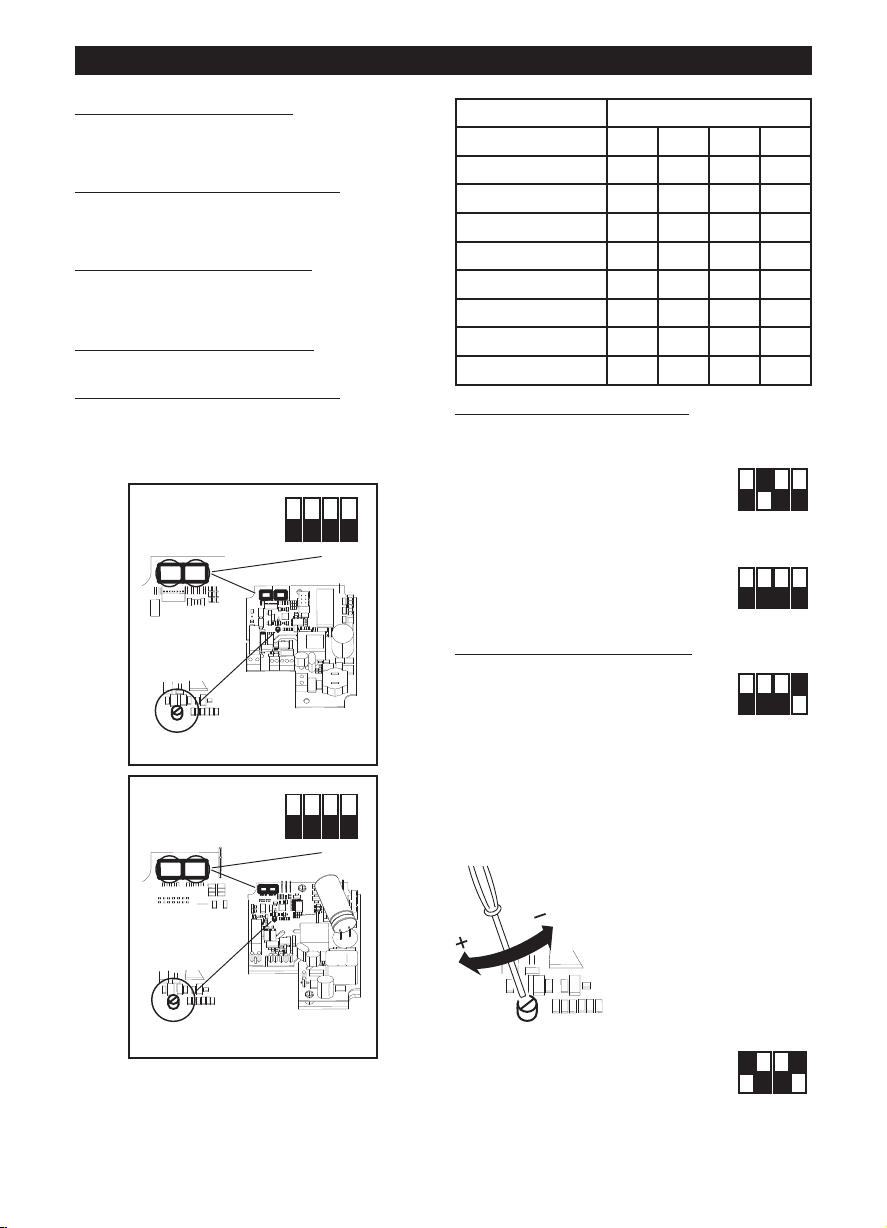
ON
1 2 3 4
OFF
ON
1 2 3 4
OFF
ON
1 2 3 4
OFF
ON
1 2 3 4
OFF
NEDERLANDS
ON
1 2 3 4
OFF
DIPSWITCH
TRIMMER
12
SW 1 : MODEL
SW 2 : SETUP
ON
1 2 3 4
OFF
DIPSWITCH
12
SW 1 : MODEL
SW 2 : SETUP
TRIMMER
Eerste configuratie
De installateur moet de werking van het apparaat
configureren door de hierna beschreven stappen te
olgen.
v
selectie van het model van het product:
Deze fase wordt uitgevoerd in de fabriek, de in dit
oekje vermelde aanwijzingen kunnen alleen nuttig
b
zijn als het noodzakelijk is de situatie te herstellen na
onbedoeld geknoei aan de dip switch.
selectie van de werkingsmodaliteit
zijn twee modi voorzien: op twee snelheden V1 en V2,
die gekozen kunnen worden met de externe
schakelaar, of met instelbare snelheid met de externe
potentiometer.
instelling van de waarden V1 en V2
werkingsmodaliteit op twee snelheden)
Selectie van het model van het product
De selectie van het model wordt uitgevoerd door het
instellen van de in de afbeelding weergegeven dip
switch 1 en zoals beschreven in de volgende tabel.
LINEO 100 Q V0 ES - LINEO 200 V0 ES
zie verderop.
: zie verderop. Er
(in het geval van
Model SW1
Int.1 Int.2 Int.3 Int.4
LINEO 100 Q V0 ES OFF OFF OFF OFF
LINEO 100 V0 ES OFF OFF OFF ON
LINEO 125 V0 ES OFF OFF ON OFF
LINEO 150 V0 ES OFF OFF ON ON
LINEO 160 V0 ES OFF ON OFF OFF
LINEO 200 V0 ES OFF ON OFF ON
LINEO 250 V0 ES OFF ON ON OFF
LINEO 315 V0 ES OFF ON ON ON
Selectie van de werkingsmodaliteit
Modus op twee snelheden:
onderbreek de elektrische voeding
stel op de in de afbeelding weergegeven dip switch
SW2 het volgende in:
Schak.2=ON; Schak.3=OFF
Schak.4=OFF
Modus op instelbare snelheid:
onderbreek de elektrische voeding;
stel op de in de afbeelding weergegeven dip switch
SW2 het volgende in:
Schak.2=OFF; Schak.3=OFF
Schak.4=OFF
Instelling van de waarden V1 en V2
Het apparaat verlaat de fabriek met de nominale
defaultwaarden V1=V
V2=V
MAX
Het is mogelijk om de waarden V1
en V2 in te stellen door als volgt te
werk te gaan:
- onderbreek de elektrische voeding
- stel op de in de afbeelding weergegeven dip-switch
2 het volgende in:
Schak.1=OFF
Schak.4=ON
- herstel de elektrische voeding. De motor wordt
automatisch op de snelheid V1temp gebracht
-- draai aan de trimmer (zie
afbeelding) om V1temp op
de gewenste waarde in te
stellen, tussen V1nom en de
in het geheugen opgeslagen
V2 – 100Rpm
MIN
,
LINEO 250 V0 ES, LINEO 315 V0 ES
26
- stel Schak.1=ON in. Dit heeft
twee effecten:
de waarde V1temp wordt in het
geheugen opgeslagen als nieuwe
V1;
de motor wordt automatisch op V2temp gebracht
- draai aan de trimmer (zie afbeelding) om V2temp op
Page 27

NEDERLANDS
O
N
1 2 3 4
O
FF
ON
1 2 3 4
O
FF
ON
1 2 3 4
OFF
ON
1 2 3 4
OFF
de gewenste waarde in te stellen, tussen de in het
eheugen opgeslagen V1nom + 100Rpm en Vmax
g
- stel Schak.1=OFF in. Dit heeft
twee effecten:
e waarde V2temp wordt in het
d
eheugen opgeslagen als nieuwe
g
2;
V
e motor wordt automatisch op V1temp gebracht
d
- onderbreek de elektrische
oeding
v
stel Schak.4=OFF in om de
waarden V1 en V2 in te stellen
Nominale waarden resetten
Indien nodig, kunnen de nominale fabriekswaarden
van V1 en V2 gereset worden, met behulp van de
volgende procedure:
- onderbreek de elektrische voeding
- stel op de in de afbeelding
weergegeven dip-switch SW2 het
volgende in:
Schak.3=ON
- herstel de elektrische voeding:
V1 en V2 worden automatisch gereset naar de
nominale fabriekswaarden met betrekking tot het
geselecteerde model, zoals hierboven is
beschreven. Het herstel van de nominale waarden
wordt aangegeven met een led die twee keer snel
knippert op de printplaat.
De motor wordt automatisch uitgeschakeld
- onderbreek de elektrische voeding
- reset op de in de afbeelding
weergegeven dip-switch SW2 het
volgende:
Schak.3=OF
Werking
Afhankelijk van de in de installatiefase gekozen
modus:
- modus op twee snelheden: het apparaat werkt
voortdurend; er kunnen twee snelheden V1 en V2
geselecteerd worden met de externe schakelaar
- modus op instelbare snelheid: het apparaat kan op
instelbare snelheid, van 300 Rpm tot Vmax (met de
externe potentiometer) werken. Ook de Vortice
ON/OFF bedieningskast + potentiometer (cod.
12826, op aanvraag) kan worden gebruikt.
VERWIJDERING
N ENKELE LANDEN VAN DE EUROPESE UNIE
I
ALT DIT PRODUCT NIET ONDER HET
V
OEPASSINGSGEBIED VAN DE NATIONALE
T
WETGEVING VOOR ERKENNING VAN DE AEEA-
ICHTLIJN EN DERHALVE BESTAAT ER GEEN
R
NKELE VERPLICHTING TOT GESCHEIDEN
E
NZAMELING AAN HET EINDE VAN DE
I
LEVENSDUUR VAN DIT PRODUCT.
Let Op
Dit apparaat is conform de EU Richtlijn 2012/19/EC.
Het symbool op het apparaat met de
afvalbak met een kruis erdoor geeft
aan dat het apparaat, aan het einde
van de levensduur, niet bij het huisvuil
gezet mag worden maar ingeleverd
moet worden bij een centrum voor
gescheiden afvalinzameling voor
elektrische en elektronische
apparaten of teruggegeven moet
worden aan de winkel op het moment
van de aanschaf van een gelijkwaardig nieuw
apparaat.
De gebruiker is verantwoordelijk voor het inleveren
van het apparaat bij een daarvoor geschikt
inzamelingspunt, op straffe van sancties op basis van
de heersende wetgeving inzake afvalverwerking.
De adequate gescheiden inzameling ten einde het
ingeleverde apparaat te kunnen recyclen, behandelen
en milieuvriendelijk tot afval te kunnen verwerken
draagt bij aan het voorkomen van mogelijk negatieve
invloeden op het milieu en de gezondheid en
bevordert de recycling van materialen waaruit het
apparaat is samengesteld.
Voor nadere informatie over de beschikbare
afvalverwerkingssystemen kunt u contact opnemen
met de plaatselijke afvalverwerkingsdienst, of bij de
winkel waar u het apparaat heeft aangeschaft.
De fabrikanten en importeurs zijn verantwoordelijk
voor de recycling, de behandeling en de
milieuvriendelijke afvalverwerking zowel direct als
door deelname aan een collectief systeem.
Onderhoud / reiniging
Fig. 27, 28, 29.
27
Page 28

SVENSKA
Var ning:
denna Symbol anger att försiktighet krä vs
för att förhindra personskador
!
Observera:
denna Symbol anger att försiktighet krävs
f
ör att förhindra skador på prod ukten
!
Beskrivning och användning
rodukten som du förvärvat är en spiral
P
centrifugalfläkt avsedd för utblåsning av luft i
ventilationsrör.
Apparaten är tillverkad av självsläckande plast V0,
den är skyddad mot vattenstänk och är utrustad med
rushless motor med två hastigheter med elektronisk
b
ontroll, med möjlighet att reglera lägsta och högsta
k
astighetsvärden.
h
Säkerhet
• Använd aldrig apparaten för annat bruk än det som
anges i detta häfte.
• Ta ur apparaten ur emballaget och kontrollera att
den är i fullgott skick. Vid tveksamhet; kontakta
genast en behörig fackman eller en serviceverkstad
som auktoriserats av Vortice. Lämna aldrig delar av
emballaget inom räckhåll för barn eller annan
oförmögen person.
• Vid användning av elektriska apparater måste vissa
grundläggande regler följas, bland annat:
- vidrör inte apparaten med våta eller fuktiga
händer;
- vidrör inte apparaten om du är barfota;
- låt inte barn eller annan oförmögen person
använda apparaten utan övervakning.
• Placera apparaten på en plats som är oåtkomlig för
barn och oförmögen person, då du har beslutat dig
för att skilja den från elnätet och inte använda den
längre.
• Använd inte apparaten i närvaro av brandfarliga
ämnen eller ångor som t.ex. sprit, insektsmedel,
bensin etc.
avpassat för apparatens maximala effekt. Om så
inte är fallet, kontakta omgående en behörig
fackman.
Stäng av strömmen med huvudströmbrytaren i
•
öljande fall: a) en funktionsstörning konstateras; b)
f
samband med underhåll, när apparatens utsida
i
skall rengöras; c) när apparaten inte skall användas
nder längre perioder.
u
För att apparaten ska fungera på korrekt sätt krävs
•
n tillfredsställande lufttillförsel i lokalen. Om en
e
annan apparat (varmvattenberedare, värmeelement
som drivs med metan, etc.) som använder luft för
förbränningen är installerad i samma lokal måste
lufttillförseln garantera att förbränningen även för
denna apparat kan ske på säkert sätt.
• Apparaten får inte användas för att aktivera
varmvattenberedare, värmeelement eller dylikt, och
den får inte heller ha utsläpp i dylika apparaters
varmluftsrör
• Apparaten skall ha utsläpp antingen eller separat rör
som används uteslutande för denna apparat.
• Se till att apparatens luftintag och luftutsläpp inte är
igentäppta eller övertäckta så att ett optimalt
luftflöde garanteras.
• Produktens utblåsningsöppningar måste alltid vara
anslutna till ett rör.
• Maximal rumstemperatur som tillåts för apparatens
funktion är 60°C, förutom för modellerna 250 och
315 där den maximala rumstemperaturen är 50°C.
• Det elektroniska styrsystemet säkerställer skydd
mot överhettning och överbelastning. Modellerna
från 100 till 250 är utrustade med värmesäkring,
medan modell 315 är utrustad med
överhettningsskydd med manuell återställning. Om
värmesäkringen utlöst måste produkten repareras
eller bytas ut, efter att man kontrollerat och åtgärdat
orsaken till att säkringen utlöst. Om skyddet med
manuell återställning har utlöst ska man koppla bort
matningsspänningen under en halvtimme. Återställ
därefter spänningen, efter att orsaken till att
skyddet utlöst har kontrollerats och åtgärdats.
• Elnätets elektriska data skall motsvara de data som
återges på apparatens märkskylt A .(Bild.A).
• Utför inte någon typ av ändringar på produkten.
• Låt inte apparaten utsättas för skadlig påverkan av
regn, snö, salt, kemiska ämnen eller liknande.
• Placera inga föremål på apparaten.
• Inspektera apparaten regelbundet och kontrollera
att den är i fullgott skick. Om fel av någon typ
upptäcks får apparaten inte användas. Kontakta
genast en återförsäljare som auktoriserats av
Vortice.
• I händelse av fel på apparaten och/eller dålig
funktion, skall apparaten stängas av och lämnas till
en av Vortice utsedd auktoriserad serviceverkstad.
Kräv att Vortice originaldelar används vid
reparationen
• Om apparaten ramlar i golvet eller tar emot hårda
stötar ska den genast kontrolleras av en
återförsäljare som auktoriserats av Vortice.
• Anslut apparaten till elnätet endast om elnätet är
28
•Denna apparat kan användas av
barn över 8 år och av personer
med nedsatt fysisk,
känslomässig eller mental
förmåga, och av personer med
bristande erfarenhet eller
kunskap, under förutsättning att
de övervakas eller att de får
anvisningar angående säker
användning av apparaten och
dess inneboende faror. Barn får
ej leka med apparaten.
Rengöring och underhåll skall
utföras av användaren och får
inte utföras av barn utan
Page 29

övervakning.
•Dessa apparater är framtagna
för hushållsbruk och
kommersiellt bruk.
•Installationen av apparaten
måste göras av en behörig
fackman.
•Det elektriska system som
produkten är kopplad till måste
överensstämma med gällande
föreskrifter.
•Installationen kräver en allpolig
brytare med minst 3 mm
kontaktöppning, som ska
garantera fullständig
frånkoppling i enlighet med
villkoren i
överspänningskategori III.
•Produkter som är försedda med
motorer som är förberedda för
enfaskoppling (M) kräver ALLTID
anslutning till 220-240V enfaslinjer (eller enbart 230V om
produkten förutsätter det. Alla
typer av ändringar kommer att
bedömas som att man mixtrat
med produkten och upphäver
produktens garanti.
styranording, och den får inte
heller kopplas till en krets som
regelbundet kopplas till eller
från.
Typiska tillämpningar
Bild 1-2;
När apparaten installeras på en höjd lägre än 2,3 m
rån marken och längden på luftintags- och
f
utblåsningsrören kräver det, är det lämpligt att
montera lämpliga anordningar för att förhindra
kontakt med fläkthjulet
Installation
Bild. 3 ÷ 26;
Bild.3: E= Märkplåt för luftflödesriktningen; C= Insug;
D= Utlopp.
Kanalfläktar och fönster/väggmonterade fläktar
Man måste vidta åtgärder för att
förhindra att gaser från
gasutloppet eller från andra
apparater med
bränsleförbränning strömmar
tillbaka in i rummet.
Fönster-/väggmonterade
fläktar
Fläkten är avsedd att monteras i
fönster eller på ytterväggar.
Apparater utrustade med
termisk brytare med manuell
återställning
För att undvika risker som är
kopplade till oavsiktlig
återställning av den termiska
brytaren får denna apparat inte
strömförsörjas via en extern
29
Page 30
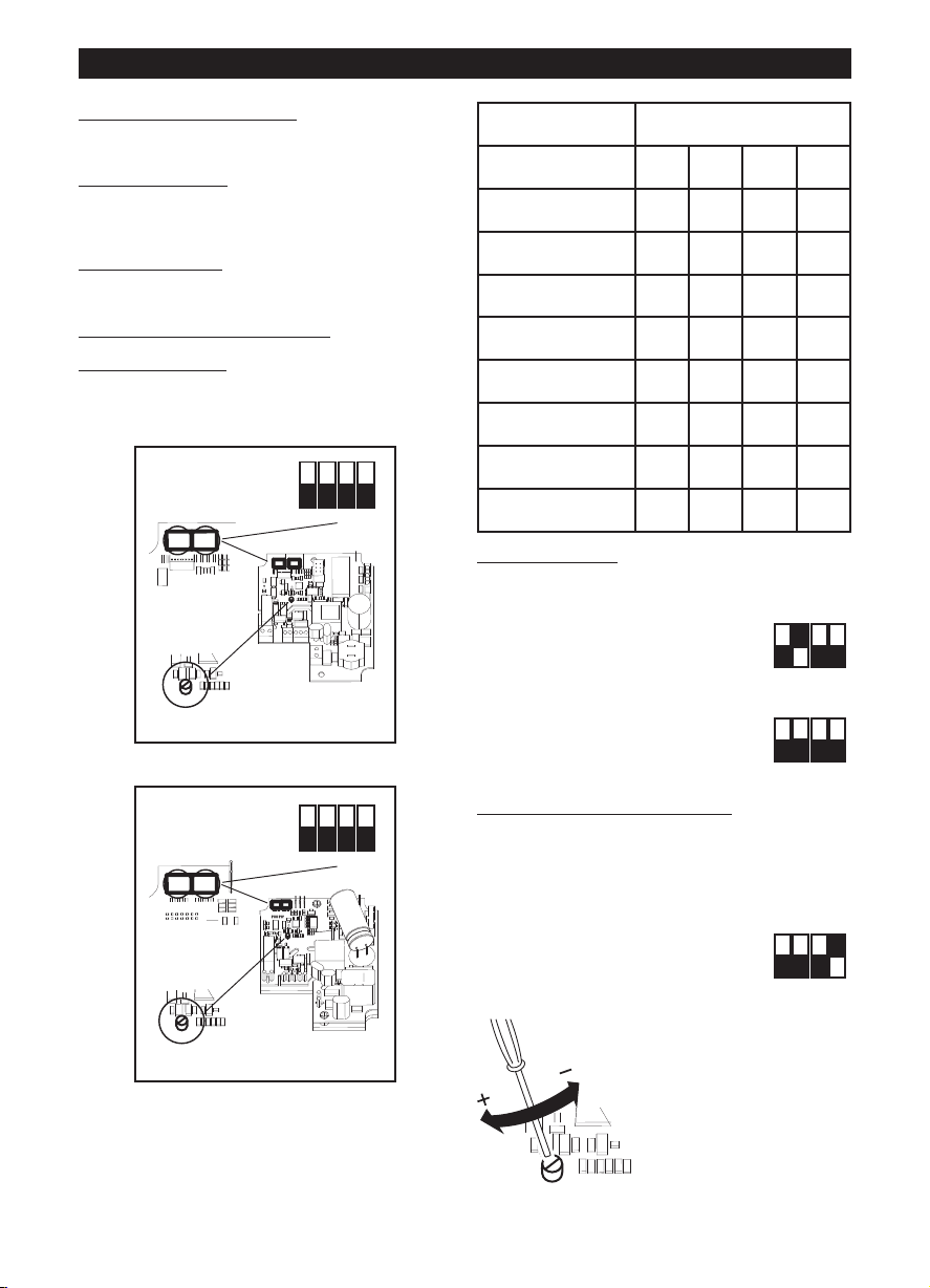
SVENSKA
ON
1 2 3 4
OFF
DIPSWITCH
TRIMMER
12
SW 1 : MODEL
SW 2 : SETUP
ON
1 2 3 4
OFF
DIPSWITCH
12
SW 1 : MODEL
SW 2 : SETUP
TRIMMER
ON
1 2 3 4
OFF
ON
1 2 3 4
OFF
ON
1 2 3 4
OFF
Startkonfigurering
nstallatören skall konfigurera apparatens funktioner i
I
de steg som beskrivs nedan.
Val av produktmodell: se nedan. Denna fas utförs på
fabriken, instruktionerna i handboken kan dock vara
till hjälp om det skulle bli nödvändigt att återställa
ituationen efter eventuell skada på data på dip-
s
mkopplaren.
o
al av funktionsläge
V
med två hastigheter, V1 och V2, som väljs med den
externa kontakten, eller med reglerbar hastighet med
hjälp av den externa potentiometern.
Inställning av värdena V1 och V2
funktion i två hastigheter)
Val av produktmodell
Val av modell utförs genom en inställning av dipomkopplaren 1, se bild, på det vis som beskrivs i
tabellen nedan
LINEO 100 Q V0 ES - LINEO 200 V0 ES
se nedan. Det finns två lägen:
:
: (vid läget med
Model SW1
Int.1 Int.2 Int.3 Int.4
LINEO 100 Q V0 ES OFF OFF OFF OFF
LINEO 100 V0 ES OFF OFF OFF ON
LINEO 125 V0 ES OFF OFF ON OFF
LINEO 150 V0 ES OFF OFF ON ON
LINEO 160 V0 ES OFF ON OFF OFF
LINEO 200 V0 ES OFF ON OFF ON
LINEO 250 V0 ES OFF ON ON OFF
LINEO 315 V0 ES OFF ON ON ON
Val av funktionsläge
Läge med två hastigheter:
Skilj apparaten från elnätet
Ställ in följande på dip-omkopplaren SW2 som visas i
bilden:
Int.2=ON (på); Int.3=OFF
Int.4=OFF (av)
Läge med reglerbar hastighet:
Skilj apparaten från elnätet
Ställ in följande på dip-omkopplaren SW2 som visas i
bilden:
Int.2=OFF (av); Int.3=OFF
Int.4=OFF (av)
Inställning av värdena för V1 och V2
Apparaten lämnar fabriken med nominella
fabriksinställningarna V1=V
Det går att reglera värdena V1 och V2 genom att göra
MIN
, V2=V
MAX
så som följer:
- Skilj apparaten från elnätet
- Ställ in följande på dip-omkopplaren SW2 som
visas i bilden:
Int.1=OFF (av)
Int.4=ON (på)
- Återanslut apparaten till elnätet.
Motorn går automatiskt till
hastigheten V1temp
- Ställ med hjälp av
LINEO 250 V0 ES, LINEO 315 V0 ES
30
trimmern (se bild) in V1temp
till det värde du önskar,
mellan V1nom och den i
minnet sparade V2 –
100Rpm
Page 31

SVENSKA
ON
1 2 3 4
OFF
ON
1 2 3 4
OFF
ON
1 2 3 4
OFF
ON
1 2 3 4
OFF
ON
1 2 3 4
OFF
- Ställ in Int.1=ON (på). Det ger två
effekter:
Värdet V1temp sparas i minnet
om ett nytt V1-värde
s
otorn går automatiskt till V2temp
M
Ställ med hjälp av trimmern (se bild) in V2temp till
det värde du önskar, mellan det minnet sparade V1
100Rpm och Vmax
+
ställ in Int.1=OFF (av). Det ger två
-
ffekter:
e
värdet V2temp sparas i minnet
som ett nytt V2-värde;
motorn går automatiskt till V1temp
- Skilj apparaten från elnätet
- Ställ in Int.4=OFF (av) för att
blockera värdena för V1 och V2
Återställning av nominella
värden
Om detta skulle vara nödvändigt kan de nominella
värdena återställas till fabriksinställningarna för V1
och V2, genom att göra följande:
- Skilj apparaten från elnätet
- Ställ in följande på dipomkopplaren SW2 som visas i
bilden:
Int.3=ON (på)
-- Återanslut apparaten till elnätet:
V1 och V2 återställs automatiskt till nominella
fabriksvärden, beroende på den modell som valts
enligt beskrivningen ovan. Återställningen av de
nominella värdena signaleras med hjälp av två
snabba blinkningar på lysdioden som sitter på
kortet. Motorn stängs automatiskt av
- Skilj apparaten från elnätet
- Återställ följande på dipomkopplaren SW2 som visas i
bilden:
Int.3=OFF (av)
Funktion
Beroende på det läge som valts under installeringen:
- Läge med två hastigheter: apparaten fungerar
kontinuerligt - det går att välja två hastigheter V1
och V2 med hjälp av den yttre kontakten
- Läge med reglerbar hastighet: apparaten kan
fungera med reglerbar hastighet, från 300 Rpm till
Vmax (med den externa potentiometern). Du kan
även använda Vortice styrbox ON/OFF +
potentiometer (kod. 12826, på begäran).
BORTSKAFFANDE
I VISSA LÄNDER I EUROPAUNIONEN FALLER
NTE DENNA PRODUKT UNDER DEN
I
NATIONELLA LAGSTIFTNINGEN SOM
INTEGRERAR DIREKTIVET OM AVFALL SOM
TGÖRS AV ELLER INNEHÅLLER ELEKTRISKA
U
LLER ELEKTRONISKA PRODUKTER.
E
SÅLUNDA FINNS DET INTE I DESSA LÄNDER
NÅGOT KRAV PÅ SEPARAT INSAMLING VAD
GÄLLER DENNA PRODUKT.
Varning
Denna produkt överensstämmer med EU
2012/19/EC direktivet.
Symbolen med det korsade kärlet
applicerad på produkten anger att
produkten, när den tjänat ut sitt syfte,
eftersom den måste hanteras separat
från hushållsavfall, måste lämnas in
till en miljöstation för elektriska och
elektroniska apparater eller
återlämnas till återförsäljaren vid
inköp av en likvärdig apparat.
Användaren är ansvarig för inlämningen av
apparaten, när den tjänat ut sitt syfte, till de avsedda
insamlingsstrukturena, i annat fall kan straff enligt
gällande lagstiftning för avfallshantering bli följden.
Den anpassade differentierade insamlingen för den
därpå följande återvinningen, hanteringen och
miljömässigt förenliga kasseringen av den avlagda
apparaten bidrar till att undvika möjliga negativa
effekter på miljön och för hälsan och underlättar
återvinningen av materialen av vilken produkten är
tillverkad.
För mer detaljerad information rörande de tillgängliga
insamlingssystemen, vänd dig till den lokala
återvinningsstationen, eller till affären där du gjort
inköpet.
Tillverkarna och importörerna tar sitt ansvar för
återvinningen, hanteringen och den miljömässigt
förenliga kasseringen såväl direkt som genom att
delta i ett kollektivt system.
Underhåll/rengöring
Bild. 27, 28, 29.
31
Page 32
SUOMI
!
Huomio:
tämä merkki varoittaa
henkilövahinkojen vaarasta
Varoitus:
tämä merkki varoittaa laitteelle
aiheutuvien vahinkojen vaarasta
!
Laitteen kuvaus ja käyttö
ankkimasi laite on keskipakopuhallin, joka imee ilman
H
ilmastointikanavaan.
Laite on valmistettu itsestään sammuvasta
kestomuovista V0 ja suojattu vesiroiskeilta.
Laitteeseen kuuluu kaksinopeuksinen, elektronisesti
hjattu harjaton moottori, jonka minimi-ja
o
aksiminopeus ovat säädettävissä.
m
Turvallisuus
• Älä käytä laitetta muuhun kuin käyttöohjekirjassa
mainittuun käyttötarkoitukseen
• Purettuasi laitteen pakkauksestaan tarkista, että se ei
ole vaurioitunut kuljetuksen aikana. Jos et ole varma
asiasta, ota yhteys Vorticen huoltoon. Älä jätä
pakkausmateriaaleja lasten tai taitamattomien
henkilöiden ulottuville.
• Kaikkien sähkölaitteiden käyttö edellyttää tiettyjen
perusmääräysten noudattamista. Näitä ovat mm.
Seuraavat:
- älä koske laitteeseen märillä tai kosteilla käsillä;
- älä koske laitteeseen ollessasi paljain jaloin;
- älä anna lasten tai taitamattomien henkilöiden
käyttää laitetta ilman valvontaa
• Vie laite pois lasten tai taitamattomien henkilöiden
ulottuvilta irrotettuasi sen sähköverkosta käytön
lopettamisen jälkeen.
• Älä käytä laitetta tulenarkojen aineiden tai höyryjen
läheisyydessä (esim. alkoholi, hyönteismyrkyt,
bensiini jne.).
• Älä tee laitteeseen minkäänlaisia muutoksia.
• Älä altista laitetta ilmastotekijöille (sade,
auringonpaiste jne.).
• Älä laita mitään esineitä laitteen päälle.
• Tarkista laitteen kunto säännöllisin väliajoin. Jos laite
ei ole moitteettomassa kunnossa, ota heti yhteys
Vorticen valtuutettuun huoltoliikkeeseen
• Jos laite ei toimi oikein ja/tai siinä on jokin vika,
käänny heti Vorticen valtuutetun jälleenmyyjän
puoleen. Mikäli laitetta joudutaan korjaamaan, vaadi
alkuperäisten varaosien käyttöä
• Jos laite putoaa tai siihen kohdistuu voimakkaita
iskuja, toimita se heti tarkastettavaksi Vorticen
valtuutettuun huoltoliikkeeseen.
• Laitteen asennuksen saa suorittaa vain
ammattitaitoinen henkilöstö.
• Kytke laite verkkovirtaan/pistorasiaan vain, jos
sähköjärjestelmän/pistorasian teho vastaa laitteen
maksimitehoa. Muussa tapauksessa käänny heti
ammattitaitoisen sähköasentajan puoleen.
• Katkaise virta päävirtakytkimestä seuraavissa
tilanteissa: a) havaitset toimintahäiriön, b) huollat tai
puhdistat laitetta ulkopuolelta, c) et aio käyttää
laitetta pitkään aikaan.
• Laitteen asianmukaisen toiminnan varmistamiseksi
32
huoneeseen tulee johtaa korvausilmaa. Jos samassa
huoneessa on polttoaineella toimiva laite
(vedenlämmitin, kaasuliesi tms.), joka ei ole
yypiltään tiivis, varmista, että korvausilma riittää
t
yös kyseisen laitteen polttoaineen täydelliseen
m
alamiseen.
p
• Laitetta ei saa käyttää vedenlämmittimen, uunin tms.
ktivaattorina, eikä sen poistoilmaa saa johtaa
a
uuman ilman kanaviin.
k
Laitteen poisto on johdettava yhteen kanavaan (jota
•
käytetään ainoastaan tälle laitteelle).
• Älä peitä tai tuki laitteen kahta imu- ja
poistosäleikköä varmistaaksesi optimaalisen
ilmanvaihdon.
• Laitteen syöttö- ja imusuulakkeet on aina liitettävä
kanavaan.
• Laitteen toiminnalle sallittu ympäristön
maksimilämpötila on 60 °C, lukuun ottamatta malleja
250 ja 315, joiden toimintaan sallittu
maksimilämpötila on 50°C.
• Suojaus ylilämpötilaa ja ylikuormitusta vastaan
taataan ohjauselektroniikalla. Mallit 100 - 250 on
varustettu suojaavalla lämpösulakkeella kun taas
malli 315 on varustettu manuaalisesti kuitattavalla
lämpösuojalla. Jos kyseessä on lämpösulakkeen
kytkeytyminen, korjaa tai vaihda tuote kun
kytkeytymisen syy on tarkastettu ja poistettu. Jos
manuaalisesti kuitattava rajoitin kytkeytyy, kytke virta
pois päältä puoleksi tunniksi ja palauta sitten
virransyöttö kun kytkeytymisen syy on tarkastettu ja
poistettu.
• Verkkovirran sähköarvojen tulee vastata laitteen
kilvessä A mainittuja tietoja (Kuva A).
•Yli 8-vuotiaat lapset sekä
henkilöt, joiden fyysinen, aistien
tai mielen terveys on
heikentynyt tai joilla ei ole
riittävää kokemusta tai taitoa,
saavat käyttää tätä laitetta vain,
jos heitä valvotaan tai jos heille
on annettu ohjeet laitteen
turvallista käyttöä varten ja he
ymmärtävät mahdolliset vaarat.
Lapset eivät saa leikkiä
laitteella. Lapset eivät saa tehdä
käyttäjän tehtäväksi tarkoitettuja
laitteen puhdistus- tai
huoltotoimenpiteitä ilman
aikuisen valvontaa.
•Nämä laitteet on suunniteltu
kotitalous- ja kaupalliseen
käyttöön.
•Laitteen asennuksen saa
suorittaa vain ammattitaitoinen
henkilöstö.
•Sähkölaitteiston johon tuote
Page 33

SUOMI
ON
1 2 3 4
OFF
DIPSWITCH
12
SW 1 : MODEL
SW 2 : SETUP
TRIMMER
ON
1 2 3 4
OFF
DIPSWITCH
TRIMMER
12
SW 1 : MODEL
SW 2 : SETUP
liitetään tulee olla voimassa
olevien lakien mukainen.
•Asennuksessa on käytettävä
kaikkinapaista katkaisinta, jonka
kosketusvälin leveys aukiasennossa on vähintään 3 mm.
Se sallii täydellisen irtikytkennän
jos kyseessä on ylijännitteen III
asettama olosuhde.
•Sellaisilla moottoreilla varustetut
tuotteet joissa on valmius
yksivaihejohdotukseen (M)
vaativat kytkennän AINA 220240 V:n yksivaihelinjoihin (tai
vain 230 V linjaan jos tuote sen
sallii). Kaiken tyyppiset
muutokset merkitsevät tuotteen
peukalointia ja saavat vastaavan
takuun raukeamaan.
Kanavatuulettimet ja
ikkuna/seinätuulettimet
Noudata tarkoituksenmukaisia
varotoimia estääksesi kaasun
takaisinvirtausta huoneeseen
hormista tai muista polttoaineita
käyttävistä laitteista.
utkien pituus edellyttää, suositeltavaa on asentaa
p
arusteet, joka estävät kosketuksen siipipyörään.
v
Asennus
uva. 3 ÷ 26;
K
uva.3: E= Ilmanvirtaussuunnan ilmaiseva kilpi; C=
K
mu; D= Puhallus.
i
Startkonfigurering
Asentajan on määritettävä laitteen toiminta
seuraavien ohjeiden mukaisesti.
Tuotteen mallin valinta:
Tämä vaihe suoritetaan tehtaalla. Tässä oppaassa
esitetyistä ohjeista voi olla hyötyä, mikäli asetukset on
palautettava dip-kytkimen vahinkokäytön vuoksi.
Toimintatilan valinta
Laitteessa on kaksi toimintatilaa: kaksinopeuksinen
toiminta nopeuksilla V1 ja V2, jotka valitaan ulkoisella
kytkimellä, sekä säädettävän nopeuden toimintatila,
jossa nopeus säädetään ulkoisella potentiometrillä.
V1- ja V2-arvojen asettaminen
käytetään kaksinopeuksisessa toimintatilassa)
Tuotteen mallin valinta
Malli valitaan säätämällä kuvassa esitettyä dipkytkintä 1 alla olevan taulukon ohjeiden mukaisesti
ohjeet jäljempänä.
: ohjeet jäljempänä.
(mikäli laitetta
Ikkuna/seinätuulettimet
Tuuletin on tarkoitettu
asennettavaksi ikkunoihin tai
ulkoseiniin.
Käsitoimisella lämpökytkimellä
varustetut laitteet
Lämpökytkimen tahattomasta
kytkeytymisestä syntyvän vaaran
välttämiseksi, tähän laitteeseen
ei saa syöttää virtaa ulkoisella
laitteella, kuten ajastin, tai sitä ei
saa kytkeä piiriin johon
syötetään säännöllisesti virtaa tai
joka kytketään säännöllisesti
pois päältä.
Tyypilliset käyttökohteet
Kuva 1-2;
Kun laite asennetaan alle 2,3 metrin korkeudelle
maasta ja mikäli imu- ja syöttökanavaan liitettyjen
LINEO 100 Q V0 ES - LINEO 200 V0 ES
LINEO 250 V0 ES, LINEO 315 V0 ES
33
Page 34

SUOMI
ON
1 2 3 4
OFF
ON
1 2 3 4
OFF
ON
1 2 3 4
OFF
ON
1 2 3 4
OFF
ON
1 2 3 4
OFF
ON
1 2 3 4
OFF
Model SW1
Int.1 Int.2 Int.3 Int.4
LINEO 100 Q V0 ES OFF OFF OFF OFF
LINEO 100 V0 ES OFF OFF OFF ON
LINEO 125 V0 ES OFF OFF ON OFF
LINEO 150 V0 ES OFF OFF ON ON
LINEO 160 V0 ES OFF ON OFF OFF
LINEO 200 V0 ES OFF ON OFF ON
LINEO 250 V0 ES OFF ON ON OFF
LINEO 315 V0 ES OFF ON ON ON
Toimintatilan valinta
Kaksinopeuksinen toimintatila:
Katkaise virta laitteesta.
Säädä kuvassa esitettyä dip-kytkintä
SW2:
kytkin 2=ON; kytkin 3=OFF
kytkin 4=OFF
Säädettävän nopeuden toimintatila:
Katkaise virta laitteesta.
Säädä kuvassa esitettyä dip-kytkintä
SW2:
kytkin 2=OFF; kytkin 3=OFF
kytkin 4=OFF
V1- ja V2-arvojen asettaminen
Laite toimitetaan tehtaalta määritettynä
oletusarvoisiin nimellisasetuksiin V1=V
V2=V
MAX
.
V1- ja V2-arvot voidaan säätää seuraavalla tavalla:
- Katkaise virta laitteesta.
- Säädä kuvassa esitettyä dipkytkintä SW2:
kytkin 1=OFF;
kytkin 4=ON;
- Kytke virta. Moottori säätyy automaattisesti
nopeudelle V1temp.
- Säädä V1temp-arvo
potentiometrillä (katso kuva)
haluttuun arvoon arvojen
V1nom ja tallennetun V2arvon - 100Rpm välille.
MIN
- Säädä V2temp-arvo potentiometrillä (katso kuva)
haluttuun arvoon tallennetun V1-arvon + 100Rpm ja
Vmax-arvon välille.
Aseta kytkin tilaan 1=OFF. Tällä on
-
aksi vaikutusta:
k
V2temp-arvo tallentuu uudeksi
2-arvoksi;
V
oottori säätyy automaattisesti nopeudelle
M
V1temp.
Katkaise virta laitteesta.
Lukitse V1 ja V2 arvot asettamalla
kytkin tilaan 4=OFF
,
- Aseta kytkin tilaan 1=ON. Tällä on
kaksi vaikutusta:
V1temp-arvo tallentuu uudeksi
V1-a rvoksi.
Moottori säätyy automaattisesti
nopeudelle V2temp.
34
Page 35

SUOMI
ON
1 2 3 4
OFF
ON
1 2 3 4
O
FF
Nimellisarvojen palauttaminen
arvittaessa tehtaan V1- ja V2-nimellisarvot voidaan
T
palauttaa seuraavalla tavalla:
- Katkaise virta laitteesta.
- Säädä kuvassa esitettyä dipkytkintä SW2:
ytkin 3=ON
k
Kytke virta:
-
1- ja V2-arvot palautuvat automaattisesti tehtaan
V
nimellisarvoihin valitun mallin mukaisesti kuten
edellä on kuvattu. Nimellisarvojen palauttaminen
ilmaistaan emolevyn kahden LED-valon nopealla
vilkkumisella. Moottori sammuu automaattisesti.
- Katkaise virta laitteesta.
- Suorita palautus kuvassa
esitetyllä dip-kytkimellä:
kytkin 3=OFF
Toiminta
Asennuksessa valitun toimintatilan mukaisesti:
- Kaksinopeuksinen toimintatila: laite toimii jatkuvasti,
ja nopeudet V1 ja V2 voidaan valita ulkoisella
kytkimellä.
- Säädettävän nopeuden toimintatila: laite toimii
säädettävällä nopeudella välillä 300 Rpm ja Vmax
(potentiometrillä). On mahdollista käyttää myös
Vortice ON/OFF -ohjausyksikköä + potentiometriä
(koodi 12826, pyynnöstä).
Huolto / Puhdistus
Kuva 27, 28, 29.
JÄTEHUOLTO
JOISSAKIN EUROOPAN YHTEISÖN MAISSA
TÄMÄ LAITE EI SISÄLLY SÄHKÖ- JA
ELEKTRONIIKKALAITTEIDEN KIERRÄTYSTÄ
ÄÄTELEVÄN WEEE-DIREKTIIVIN ALAISUUTEEN
S
IKÄ NÄISSÄ MAISSA TÄTEN VAADITA LAITTEEN
E
RILLISTÄ JÄTEHUOLTOKÄSITTELYÄ KÄYTTÖIÄN
E
LOPUSSA.
Huomio!
Tämä tuote vastaa EU-direktiiviä 2012/19/EC.
Symbolen med det korsade kärlet
applicerad på produkten anger att
produkten, när den tjänat ut sitt syfte,
eftersom den måste hanteras separat
från hushållsavfall, måste lämnas in
till en miljöstation för elektriska och
elektroniska apparater eller
återlämnas till återförsäljaren vid
inköp av en likvärdig apparat.
Käyttäjä vastaa käytetyn laitteen toimittamisesta
oikeaan keräyskeskukseen voimassa olevien
jätehuoltoa koskevien lakien määräämien
rangaistusten uhalla.
Asianmukainen jätteiden lajittelu laitteen materiaalien
kierrättämistä, käsittelyä ja
ympäristönsuojelumääräysten mukaista hävittämistä
varten auttaa välttämään ympäristö- ja terveyshaittoja
ja helpottaa tuotteen eri materiaalien kierrätystä.
Lisätietoja käytettävissä olevista keräysjärjestelmistä
antaa paikallinen jätehuolto tai liike, josta laite on
ostettu.
Valmistajat ja maahantuojat täyttävät velvollisuutensa
pitämällä huolta kierrätyksestä, käsittelystä ja
ympäristönsuojelumääräysten mukaisesta
hävittämisestä joko suoraan tai osallistumalla
kollektiiviseen järjestelmään.
35
Page 36

ROMÂNĂ
Atenţie:
acest simbol indică măsuri de precauţie
necesare pentru a evita producerea de pagube
utilizatorului
!
Măsuri de precauţie:
acest simbol indică măsuri de precauţie
necesare pentru a evita defectarea produsului
!
Descrierea şi utilizarea
Aparatul pe care l-aţi cumpărat este un aspirator
elicoidal-centrifugal de conductă, pentru evacuarea
erului într-o conductă de aerisire.
a
paratul este construit din răşină termoplastică cu
A
autostingere V0, este protejat împotriva stropilor de
apă şi este dotat cu motor brushless cu două viteze, cu
ontrol electronic, cu posibilitatea de reglare a valorilor
c
e viteză minimă şi maximă.
d
Siguranţa
• Nu utilizaţi acest produs în scopuri diferite de cele
prezentate în acest manual.
• După ce aţi despachetat produsul, verificaţi
integritatea acestuia; dacă aveţi dubii, adresaţi-vă
imediat unui dealer autorizat Vortice. Nu lăsaţi
componentele ambalajului la îndemâna copiilor sau
a persoanelor cu handicap.
• Folosirea oricărui aparat electric presupune
respectarea unor reguli fundamentale, printre care:
- nu îl atingeţi cu mâinile ude sau umede;
- nu îl atingeţi când sunteţi desculţ;
- nu permiteţi copiilor sau persoanelor cu handicap,
nesupravegheate, să-l folosească.
• Puneţi aparatul astfel încât să nu fie la îndemâna
copiilor şi a persoanelor cu handicap, în momentul în
care hotărâţi să îl deconectaţi de la reţeaua electrică
şi să nu îl mai folosiţi.
• Nu utilizaţi aparatul în prezenţa substanţelor sau a
vaporilor inflamabili, ca de exemplu alcool,
insecticide, benzină etc.
• Nu aduceţi niciun fel de modificare aparatului.
• Nu lăsaţi aparatul expus la agenţi atmosferici (ploaie,
soare etc.).
• Nu puneţi obiecte pe aparat.
• Verificaţi periodic integritatea aparatului. În cazul unor
imperfecţiuni, nu utilizaţi aparatul şi contactaţi
imediat un dealer autorizat Vortice.
• În cazul unei funcţionări defectuoase şi/sau a unei
defectări a aparatului, adresaţi-vă imediat unui
dealer autorizat Vortice şi cereţi, pentru eventualele
reparaţii, folosirea pieselor de schimb Vortice
originale.
• Dacă aparatul cade sau primeşte lovituri puternice,
rugaţi să fie verificat imediat de un dealer autorizat
Vortice.
• Instalarea aparatului trebuie să fie efectuată de către
personal calificat din punct de vedere profesional.
• Conectaţi aparatul la reţeaua de alimentare/priza
electrică doar dacă puterea instalaţiei/prizei este
adecvată pentru puterea sa maximă. În caz contrar,
adresaţi-vă imediat personalului calificat din punct
de vedere profesional.
• Stingeţi întrerupătorul general al instalaţiei: a) când
36
bservaţi o anomalie în funcţionare; b) când hotărâţi
o
să efectuaţi o operaţiune de curăţare la exterior; c)
când hotărâţi să nu utilizaţi aparatul pe perioade mai
lungi.
• Este indispensabil să asiguraţi afluxul necesar de
er în încăpere pentru a garanta funcţionarea
a
rodusului. În cazul în care în aceeaşi încăpere mai
p
ste instalat un aparat care funcţionează cu
e
combustibil (boiler, sobă cu metan etc.), care nu este
etanş, asiguraţi-vă că afluxul de aer garantează şi
perfecta combustie a acestui aparat.
• Aparatul nu poate fi utilizat pentru a activa boilere,
sobe etc. şi nici nu trebuie să evacueze în
conductele de aer cald.
• Aparatul trebuie să evacueze într-o conductă
separată (utilizată doar de către acest produs).
• Nu acoperiţi şi nu astupaţi gurile de aspiraţie şi de
evacuare ale aparatului, astfel încât să se asigure o
circulaţie optimă a aerului.
• Gurile de evacuare şi de aspiraţie ale aparatului
trebuie să fie întotdeauna conectate la o conductă.
• Temperatura maximă a mediului ambiant pentru
funcționarea aparatului este de 60 ° C, cu excepția
modelelor 250 și 315 pentru care este de 50°C.
• Protecția împotriva supraîncălzirii și supraîncărcării
este asigurată de sistemul electronic de comandă.
Modelele de la 100 la 250 sunt echipate cu o
siguranță de protecție, în timp ce modelul 315 este
echipat cu o protecție termică cu resetare manuală.
În cazul intervenției siguranței termice, reparați sau
înlocuiți produsul, după ce ați verificat și ați
îndepărtat cauza intervenției. În cazul intervenției
limitatorului cu resetare manuală, opriți alimentarea
cu energie electrică timp de o jumătate de oră și apoi
conectați din nou, după ce ați verificat și eliminat în
prealabil cauza intervenției.
• Parametrii electrici ai reţelei trebuie să corespundă
cu cei de pe plăcuţa A (Fig.A).
•Acest aparat poate fi utilizat de
copii începând de la vârsta de 8
ani şi de persoane cu capacităţi
fizice, senzoriale sau mentale
reduse, sau lipsite de experienţă
şi de cunoştinţe, dacă sunt
supravegheate sau dacă au fost
instruite în legătură cu folosirea
aparatului în siguranţă şi dacă
înţeleg care sunt pericolele care
pot fi cauzate de acesta. Copiii
nu trebuie să se joace cu
aparatul. Operaţiile de curăţare
şi întreţinere care pot fi efectuate
de utilizator nu trebuie să fie
efectuate de copii
nesupravegheaţi.
•Aceste aparate au fost
proiectate pentru a fi utilizate în
mediul casnic şi comercial.
Page 37

ROMÂNĂ
ON
1 2 3 4
OFF
DIPSWITCH
12
SW 1 : MODEL
SW 2 : SETUP
TRIMMER
•Instalarea aparatului trebuie să
fie efectuată de către personal
calificat din punct de vedere
profesional.
•Instalația electrică la care este
conectat produsul trebuie să
respecte normele în vigoare.
•Pentru instalare, este nevoie de
un întrerupător omnipolar cu o
distanță de deschidere a
contactelor egală cu sau mai
mare de 3 mm, care să permită
deconectarea completă în
condiții de supratensiune de
categoria III.
•Produsele echipate cu motoare
adecvate pentru cablajul
monofazat (M) necesită
ÎNTOTDEAUNA conexiunea la
linii monofazate de 220-240V
(sau doar de 230 V când acest
lucru este prevăzut). Orice tip de
modificare este considerată
folosire incorectă a produsului și
anulează garanția.
Ventilatoare de conductă și
fereastră-zid
Este necesar să luați măsuri de
precauție pentru a evita prezența
refluxului de gaze provenite de la
canalul de evacuare a gazelor
sau de la alte aparate cu
combustie de carburant.
de manevră extern, precum un
temporizator și nici nu trebuie
conectat la un circuit alimentat
regulat sau deconectat de la
serviciu.
Aplicaţii tipice
Fig. 1-2;
Când aparatul este instalat la o înălţime mai mică de
2,3 m de podea, iar lungimea conductelor conectate la
aspiraţie şi la evacuare necesită acest lucru, este
necesar să se monteze dispozitive care să împiedice
riscul de contact cu rotorul
Instalarea
Figg 3 ÷ 26.
Fig.3: E= Plăcuţă care indică direcţia fluxului de aer;
C=Aspiraţie; D= Evacuare;
Configuraţia iniţială
Instalatorul trebuie să configureze funcţionarea
aparatului urmând etapele descrise mai jos.
Selectarea modelului produsului:
Această etapă este efectuată în fabrică, instrucţiunile
din această broşură pot fi utile numai în cazul în care
este necesar să se restabilească situaţia în urma unor
manipulări accidentale ale comutatorului „dip switch”.
Selectarea modului de funcţionare
prevăzute două modalităţi: cu două viteze, V1 şi V2,
care pot fi selectate de la întrerupătorul extern, sau cu
viteză reglabilă prin intermediul potenţiometrului
extern.
Setarea valorilor pentru V1 şi V2
funcţionare cu două viteze).
Selectarea modelului produsului
Selectarea modelului se efectuează cu ajutorul
comutatorului „dip switch” 1 indicat în figură, aşa cum
se descrie în tabelul de mai jos.
vezi mai jos.
: vezi mai jos. Sunt
(în cazul modului de
Ventilatoare de fereastră-zid
Ventilatorul este conceput pentru
a fi montat pe ferestre sau ziduri
externe.
Aparate echipate cu dispozitiv
de întrerupere termică cu
rearmare manuală
Pentru a evita orice pericol
datorat rearmării accidentale a
dispozitivului termic de
întrerupere, aparatul nu trebuie
alimentat folosind un dispozitiv
LINEO 100 Q V0 ES - LINEO 200 V0 ES
37
Page 38

ROMÂNĂ
ON
1 2 3 4
OFF
D
IPSWITCH
TRIMMER
1
2
SW 1 : MODEL
S
W 2 : SETUP
ON
1 2 3 4
OFF
ON
1 2 3 4
OFF
ON
1 2 3 4
OFF
ON
1 2 3 4
OFF
ON
1 2 3 4
OFF
ON
1 2 3 4
OFF
LINEO 250 V0 ES, LINEO 315 V0 ES
Model SW1
Setarea valorilor pentru V1 şi V2
Aparatul iese din fabrică având setările nominale
implicite V1=V
Este posibil să se regleze valorile pentru V1 şi V2
rocedând astfel:
p
întrerupeţi alimentarea cu
lectricitate
e
- setaţi pe comutatorul „dip switch”
MIN
, V2=V
MAX
SW2 indicat în figură:
Într.1=OFF (Oprit)
Într. 4=ON (Pornit)
- restabiliţi alimentarea cu electricitate. Motorul
ajunge automat la viteza V1temp
-- cu ajutorul condensatorului
de reglare (vezi figura), reglaţi
V1temp pe valoarea dorită,
cuprinsă între V1nom şi V2
memorată – 100Rpm
LINEO 100 Q V0 ES OFF OFF OFF OFF
Selectarea modului de funcţionare
Modul cu două viteze:
întrerupeţi alimentarea cu electricitate
setaţi pe comutatorul „dip switch” SW2 indicat în
figură:
Într. 2=ON (Pornit); Într. 3=OFF
Într. 4=OFF (Oprit)
Modul cu viteză reglabilă:
întrerupeţi alimentarea cu
electricitate
setaţi pe comutatorul „dip switch” SW2 indicat în
figură:
Într. 2=OFF (Oprit); Într. 3=OFF
Într. 4=OFF (Oprit)
Int.1 Int.2 Int.3 Int.4
LINEO 100 V0 ES OFF OFF OFF ON
LINEO 125 V0 ES OFF OFF ON OFF
LINEO 150 V0 ES OFF OFF ON ON
LINEO 160 V0 ES OFF ON OFF OFF
LINEO 200 V0 ES OFF ON OFF ON
LINEO 250 V0 ES OFF ON ON OFF
LINEO 315 V0 ES OFF ON ON ON
- setaţi Într. 1=ON (Pornit). Acest
lucru are două efecte:
valoarea V1temp este memorată
ca noua valoare pentru V1
motorul ajunge automat la V2temp
- cu ajutorul condensatorului de reglare (vezi figura),
reglaţi V2temp pe valoarea dorită, cuprinsă între V1
memorată + 100Rpm şi Vmax
- setaţi Într. 1=OFF (Oprit). Acest
lucru are două efecte:
valoarea V2temp este memorată
ca noua valoare pentru V2;
motorul ajunge automat la V1temp
- întrerupeţi alimentarea cu
electricitate
- setaţi Într. 4=OFF (Oprit) pentru a
bloca valorile pentru V1 şi V2
38
Page 39

ROMÂNĂ
ON
1 2 3 4
O
FF
ON
1 2 3 4
OFF
Resetarea valorilor nominale
acă este necesar, se pot reseta valorile nominale din
D
fabrică pentru V1 şi V2, prin intermediul următoarei
proceduri:
- întrerupeţi alimentarea cu
electricitate
setaţi pe comutatorul „dip switch”
-
W2 indicat în figură:
S
ntr. 3=ON (Pornit)
Î
- restabiliţi alimentarea cu electricitate:
V1 şi V2 sunt resetate automat la valorile nominale
din fabrică pentru modelul selectat, aşa cum se
arată mai sus. Efectuarea resetării valorilor
nominale este semnalată cu două clipiri rapide ale
unui led de pe cartela electronică. Motorul este
dezactivat în mod automat
- întrerupeţi alimentarea cu
electricitate
- resetaţi pe comutatorul „dip switch”
SW2 indicat în figură:
Într. 3=OFF (Oprit)
Funcţionarea
În funcţie de modul ales în faza de instalare:
- modul cu două viteze: aparatul funcţionează în mod
continuu; se pot selecta două viteze, V1 şi V2, prin
intermediul întrerupătorului extern
- modul cu viteză reglabilă: aparatul poate funcţiona
cu viteză reglabilă, de la 300 la Vmax
(potenţiometrului extern.).
Se poate utiliza şi cutia de comenzi Vortice ON/OFF
+ potenţiometru (cod 12826, la cerere).
Întreţinerea / Curăţarea
Fig 27, 28, 29.
ELIMINARE
ÎN UNELE ŢĂRI DIN UNIUNEA EUROPEANĂ ACEST
PRODUS NU INTRĂ ÎN DOMENIUL DE APLICARE
L LEGII NAŢIONALE DE RECEPTARE A
A
IRECTIVEI DEEE ȘI, PRIN URMARE, ÎN ACESTEA
D
NU E ÎN VIGOARE OBLIGAŢIA DE RECICLARE LA
ERMINAREA DURATEI DE VIAŢĂ.
T
Atenţie
Acest produs e conform cu Directiva EU 2012/19/EC.
Simbolul pubelei barate de pe aparat
indică faptul că produsul, la
terminarea vieţii utile, trebuie să fie
tratat în mod separat faţă de deșeurile
menajere și trebuie predat la un
centru de colectare pentru reciclarea
aparatelor electrice și electronice sau
trebuie predat vânzătorului când se
cumpără un aparat nou echivalent.
Utilizatorul e responsabil de predarea aparatului, la
terminarea duratei de viaţă utilă, către structurile
corespunzătoare de colectare, sub pedeapsa
sancţiunilor prevăzute de legislaţia în vigoare privind
deșeurile.
Colectarea diferenţiată corespunzătoare, pentru
trimiterea ulterioară a aparatului casat spre a fi
reciclat, tratat și eliminat în mod compatibil cu mediul
înconjurător, contribuie la evitarea posibilelor
efecte negative asupra mediului și asupra sănătăţii
persoanelor și favorizează reciclarea materialelor din
care e fabricat produsul.
Pentru informaţii mai detaliate privind
sistemele de colectare disponibile, adresaţi-vă
serviciului local de eliminare a deșeurilor sau
magazinului în care a fost cumpărat produsul.
Producătorii și importatorii își îndeplinesc obligaţiile
privind reciclarea, tratarea și eliminarea în mod
compatibil cu mediul înconjurător fie direct, fie prin
participarea la un sistem colectiv.
39
Page 40

РУССКИЙ
Oсторожно:
меры
предосторожности, необходимые для
безопасности пользователя
!
Вниманиe:
меры
предосторожности, необходимые для
обеспечения сохранности изделия
!
Описание изделия и способ
его применения
риобретенное вами изделие представляет собой
П
ентробежный винтовой канальный вытяжной
ц
вентилятор, предназначенный для удаления
оздуха через вентиляционный воздуховод.
в
орпус прибора выполнен из самогасящегося
К
ермопластика V0; прибор защищен от брызг воды
т
и оснащен двухскоростным бесщеточным
двигателем с электронным управлением с
возможностью задания минимальной либо
максимальной скорости.
Правила техники
безопасности
• Не используйте это изделие для целей, отличных
от предусмотренных настоящей инструкцией.
• После распаковки изделия убедитесь в его
целости и сохранности; в случае сомнений
немедленно обращайтесь к авторизованному
дилеру компании Vortice. Не допускайте
попадания элементов упаковки в руки детей или
лиц с ограниченной дееспособностью.
• Эксплуатация любого электрического устройства
требует соблюдения некоторых основных
правил, в том числе:
- не следует касаться его мокрыми или
влажными руками;
- не следует касаться его, стоя на полу босыми
ногами;
- запрещается его эксплуатация детьми или
недееспособными лицами, находящимися без
присмотра.
• В случае принятия решения об отключения
устройства от сети и прекращения его
использования поместите его в такое место, где
бы оно не могло попасть в руки детей или
недееспособных лиц.
• Не эксплуатируйте изделие в присутствии
воспламеняемых веществ или паров, таких как
спирт, инсектициды, бензин и т.д.
• Не подвергайте изделие никаким модификациям
или доработкам.
• Не допускайте, чтобы изделие подвергалось
воздействию атмосферных агентов (дождь,
солнце и т.д.).
• Не кладите на изделие какие-либо предметы.
• Периодически проверяйте состояние изделия. В
случае неверной работы не эксплуатируйте
изделие и немедленно обратитесь к
авторизованному дилеру компании Vortice.
• В случае ненормальной работы и/или
неисправности изделия, немедленно обратитесь
40
к авторизованному дилеру компании Vortice; при
необходимости проведения ремонта запросите
оригинальные запчасти компании Vortice
• В случае падения изделия или получения им
ильных ударов немедленно обратитесь к
с
вторизованному дилеру компании Vortice для
а
го проверки.
е
• Установка изделия должна производится
квалифицированным персоналом
• Подключайте изделие к сети питания/розетке
только в том случае, если их параметры
соответствуют его максимальной мощности. В
противном случае немедленно обратитесь к
квалифицированному специалисту.
• В следующих случаях выключайте рубильник: а)
при проявлении неисправностей в
функционировании изделия; b) при выполнении
внешней чистки изделия; c) в случае принятия
решения о неиспользовании изделия в течение
продолжительного времени.
• Для правильной работы изделия необходимо
обеспечить приток в помещение достаточного
количества воздуха. В случае, когда в таком
помещении установлен прибор негерметичного
типа, работающий за счет сгорания топлива
(водонагревательный котел, печь, работающая
на метане, и т.д.), необходимо удостовериться в
том, что приток воздуха достаточен и для
обеспечения хорошего горения в его камере
сгорания.
• Данное изделие нельзя использовать в качестве
активирующего элемента для
водонагревательных котлов, печей и т.д.;
запрещается также выброс воздуха с него в
воздуховоды горячего воздуха подобных
устройств.
• Всасываемый вентилятором воздух должен
удаляться через отдельный воздуховод
(используемый только для этого изделия) или
непосредственно выводиться наружу.
• Не закрывайте и не загораживайте решетки на
всасывающем и выпускном отверстиях изделия,
чтобы не создавать преграды оптимальному
прохождению воздуха.
• Нагнетательный и всасывающий патрубки
прибора должны всегда подсоединяться к
воздуховоду
• Максимальная температура окружающей среды
для прибора составляет 60°C, за исключением
моделей 250 и 315, для которых она составляет
50°C.
• Защита от перегрева и перегрузки
обеспечивается электроникой управления.
Модели 100-250 оснащены теплозащитным
предохранителем, а модель 315 - тепловой
защитой с ручным сбросом. В случае
срабатывания теплового предохранителя,
отремонтируйте или замените продукт после
проверки и устранения причины срабатывания.
Если сработал ограничитель с ручным сбросом,
отключите питание на полчаса, а затем снова
включите после проверки и устранения причины
срабатывания.
• Параметры электрической сети должны
соответствовать приведенным на табличке А
(рис. А).
Page 41

РУССКИЙ
ж
мо
р
о
б
и
р
п
ый
н
н
Да
•
ми
ь
т
де
я
с
ь
т
а
в
о
з
ь
л
о
п
с
и
ми
а
ц
ли
и
т
ле
8
т
о
е
т
с
а
р
з
о
в
и
к
с
е
ч
и
з
и
ф
ыми
н
н
е
ч
и
н
а
р
г
о
венными
и
д п
о
ы п
н
с
о
п
е
п
с
ь
в
м, н
е
деть
ься
о
х
а
мст
о
е
о
п
п
ып
дят
л
х
б
с
и
р
р
ь
л
с
и
р
з
о
р
о
до
е
ми, ес
с
н
и
ди
о
т
мо
и
в
а
а
в
о
з
н
з
о
э
яй
л
о
в
о
б
и
е
н
л
л
я п
мых
р
л
н
а
т
о
р
н
ж
орными или у
сенс
ями
т
с
о
н
б
о
с
о
п
с
н
ми
ющи
ме
и
а и навыков, если они
опыт
я п
с
дят
о
х
а
н
че
у
н
с
а
п
я и
и
л
в
т
с
т
с
о
н
а
ж
е
а
в
о
з
е
б
и
о
г
о
ющи
у
. Не
и
т
а
р
г
ход за прибором,
е
щи
л
е
т
т
н
о
и
л
и
о
з
е
б
де
з
и
ще
у
с
с
а
п
о
ям и
т
де
Чистка и у
дл
о
п
ь
л
о
п
уществля
ос
н
и
н
о
присмотром.
и
ые
н
н
•Да
о
б
а
р
з
а
р
использования
бытовог
назнач
Установка изделия должна
•
о или коммерч
ения
з
ы дл
н
а
т
в помещения
.
я б
и
л
де
ыл
еског
п р о и з в о д и т ь с я
к в а л и ф и ц и р о в а н н ы м и
специалистами.
•Электрическая
которой
подключен
сеть,
продукт,
должна соответствовать
ействующим стандартам.
д
быть
•Д
установки
я
л
долж
ен
п р е д у с м о т р е н
с е н а
в
п
ы й
н
н
л е
а в
р
выключатель с расстоянием
открытия контакта 3 мм и
более, что обеспечит полное
отключение в условиях
категории перенапряжения
Оборудование, оснащенное
•
д в и г а т е л я м и ,
предрасположенными к
однофазной проводке (М),
ВСЕГДА требует подключения
к однофазным линиям с
т
е
ми
напряжением 220-240 В (или
в
только 230 В, если это
с
предусмотрено). Любые
,
изменения считаются порчей
изделия, что приведет к
е
аннулированию Гарантии.
Канальные вентиляторы,
м
о
оконные и настенные
м
а
Следует принять меры
я
и
предосторожности, чтобы
ют
избежать в помещении
м
о
обратного потока газов,
е
т
идущих из трубы отвода газов
м.
или других приборов,
сжигающих топливо.
ю
и
ы
н
Оконные и настенные
ли
вентиляторы
д
о
Вентилятор предназначен для
установки на окнах или на
и
наружных стенах.
я
Приборы, оснащенные
х
устройством отключения
о
при перегреве с ручным
сбросом
Во избежание каких-либо
опасностей по причине
случайного сброса устройства
теплового отключения этот
к
прибор не должен получать
питание от внешнего
устройства коммутации,
например, таймер, а также не
должен быть подключен к
цепи, которая регулярно
питается или отключается
службой энергоснабжения
Обычные виды применения
III.
Рис. 1-2;
Если вентилятор устанавливается на высоте,
меньшей, чем 2,3 метра от пола, и этого требует
длина воздуховодов нагнетания и всасывания,
целесообразно установить устройства,
предотвращающие случайный контакт с
крыльчаткой
41
Page 42
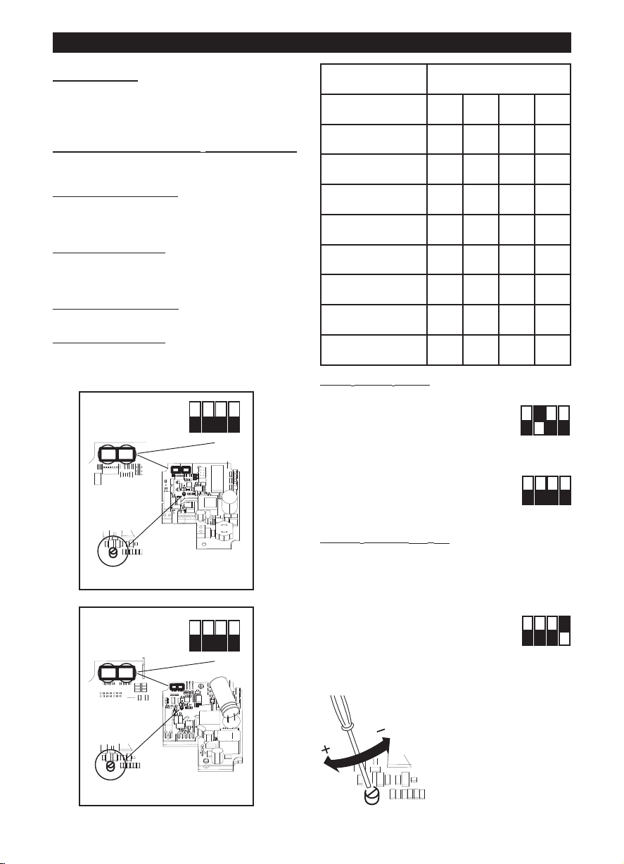
ON
1 2 3 4
OFF
DIPSWITCH
TRIMMER
12
SW 1 : MODEL
SW 2 : SETUP
РУССКИЙ
ON
1 2 3 4
OFF
DIPSWITCH
12
SW 1 : MODEL
SW 2 : SETUP
TRIMMER
ON
1 2 3 4
OFF
ON
1 2 3 4
OFF
ON
1 2 3 4
OFF
Установка
Р
Р
потока; C = Всасывание; D = Нагнетание;
Первоначальная настройка
У
с
выбор
выполняется на заводе-изготовителе;
приведенные в настоящем руководстве указания
могут быть полезными только в случае случайного
изменения установки внутренних перемычек.
выбор
два режима: с двумя скоростями V1 и V2,
выбираемыми с при помощи внешнего
переключателя; исрегулируемой - при помощи
внешнего потенциометра - скоростью.
задание
с двумя скоростями)
Выбор модели изделия
Выбор модели производится путем установки
внутренних перемычек, показанных на рисунке, в
соответствии с приведенной ниже таблицей.
ис. 3÷26
ис.3: E = Таблица направления воздушного
становщик должен задать режим работы прибора,
ледуя приведенным ниже указаниям.
модели изделия: см. ниже. Этот этап
режима работы: см. ниже. Предусмотрены
значений V1 и V2 (в случае режима работы
LINEO 100 Q V0 ES - LINEO 200 V0 ES
Model SW1
Int.1 Int.2 Int.3 Int.4
LINEO 100 Q V0 ES OFF OFF OFF OFF
LINEO 100 V0 ES OFF OFF OFF ON
LINEO 125 V0 ES OFF OFF ON OFF
LINEO 150 V0 ES OFF OFF ON ON
LINEO 160 V0 ES OFF ON OFF OFF
LINEO 200 V0 ES OFF ON OFF ON
LINEO 250 V0 ES OFF ON ON OFF
LINEO 315 V0 ES OFF ON ON ON
Выбор режима работы
Режим работы с двумя скоростями:
отключите электропитание
установите внутренние перемычки,
показанные на рисунке:
Int.2=ON; Int.3=OFF
Int.4=OFF
Режим работы с регулируемой скоростью:
отключите электропитание
установите внутренние перемычки,
показанные на рисунке:
Int.2=OFF; Int.3=OFF
Int.4=OFF
значений V1 и V2
Задание
Прибор отгружается с завода-изготовителя с
заданными по умолчанию номинальными
значениями V1=V
Значения V1 и V2 можно отрегулировать, действуя
следующим образом:
- отключите электропитание
- установите внутренние
перемычки, показанные на
рисунке:
Int.1=OFF
Int.4=ON
- подайте электропитание. При этом двигатель
автоматически установится на скорость V1temp
, V2=V
MIN
MAX
- с помощью потенциометра
(см. рисунок) отрегулируйте
V1temp на нужное
значение в пределах от
V1nom до сохраненного в
памяти значения V2 –
100Rpm
LINEO 250 V0 ES, LINEO 315 V0 ES
42
Page 43

РУССКИЙ
ON
1 2 3 4
OFF
ON
1 2 3 4
OFF
ON
1 2 3 4
OFF
ON
1 2 3 4
OFF
ON
1 2 3 4
OFF
задайте Int.1=ON. Это дает
-
двойной результат:
значение V1temp сохраняется в
качестве нового значения V1;
вигатель автоматически устанавливается на
д
корость V2temp
с
с помощью потенциометра (см. рисунок)
-
трегулируйте V2temp на нужное значение в
о
пределах от сохраненного в памяти значения V1
+ 100Rpm до Vmax
- задайте Int.1=OFF. Это дает
двойной результат:
значение V2temp сохраняется в
качестве нового значения V2;
двигатель автоматически устанавливается на
скорость V1temp
- отключите электропитание
- задайте Int.4=OFF для фиксации
значений V1 и V2
Восстановление
номинальных значений
В случае необходимости можно восстановить
номинальные заводские значения V1 и V2 с
помощью следующей операции:
- отключите электропитание
- установите внутренние
перемычки, показанные на
рисунке:
Int.3=ON
- подайте электропитание:
V1 и V2 автоматически вернутся к номинальным
заводским значениям, соответствующим модели,
выбранной указанным выше образом. На
восстановление номинальных значений укажут
два быстрых мигания светодиода,
установленного на приборе.
При этом двигатель автоматически выключится
- отключите электропитание
- верните внутренние перемычки,
показанные на рисунке, в
исходное положение:
Int.3=OFF
Функционирование
В зависимости от режима работы, выбранного на
этапе установки:
- режим работы с двумя скоростями: прибор
работает непрерывно; с помощью внешнего
переключателя можно выбрать одну из двух
скоростей V1 и V2
- режим работы с регулируемой скоростью: прибор
может работать со скоростью, регулируемой в
диапазоне от 300 до Vmax (внешнего
потенциометра). Возможно также использование
коробки управления Vortice ВКЛ/ВЫКЛ +
потенциометр (код 12826, поставляется по
отдельному заказу).
Техобслуживание/Чистка
Рис. 27, 28, 29.
43
Page 44

A
A
FIGURE
FIGURES
FIGURES
ABBILDUNGEN
FIGURAS
FIGUREN
FIGURER
K U VAT
FIGURILE
ИЛЛЮСТРАЦИИ
1
44
Page 45
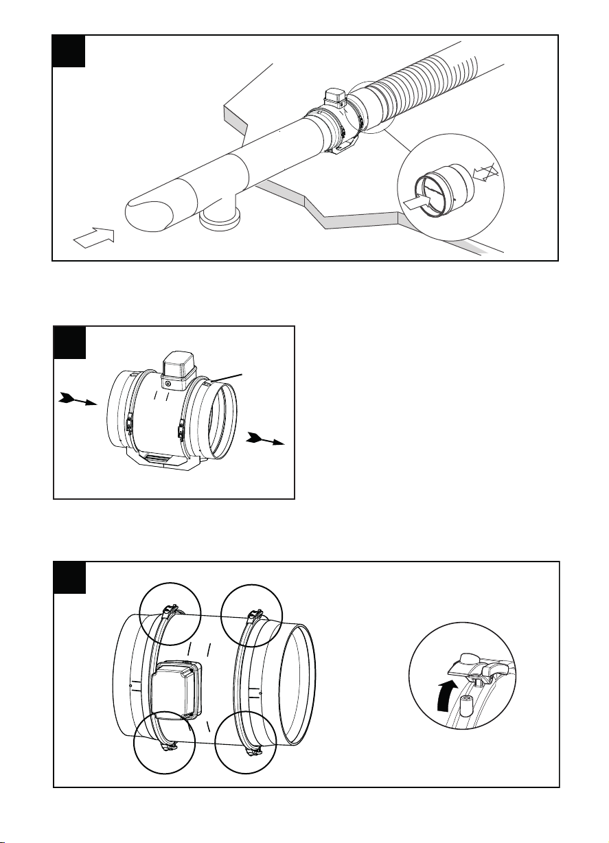
2
2 2
E
3 3
D
C
4 4
45
Page 46
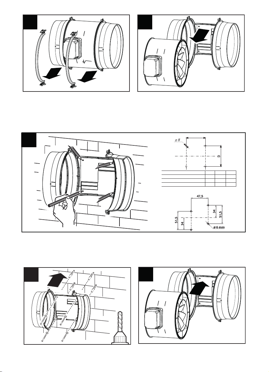
5 5
6 6
7 7
G
Vortice Lineo 100 Q V0 ES
D E Ø F
100-125 -150-160 60 80 6
200 94 100 6
Vortice Lineo V0 ES
315 178 182 8
8 8
9 9
46
Page 47
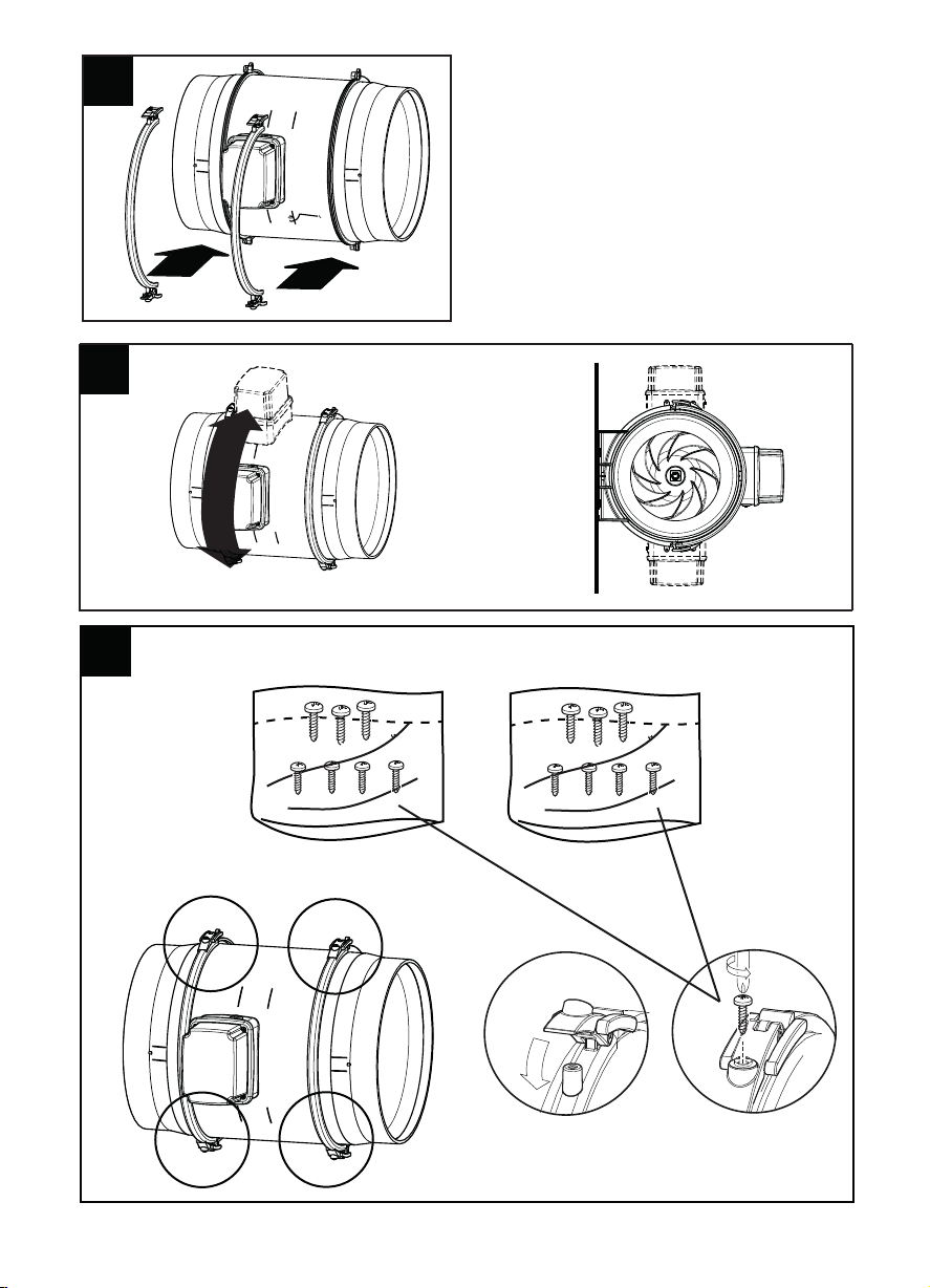
10 10
11 11
12 12
LINEO 100 - 200
3X10
3,5X13
3,5X13
3,5X16
LINEO 250 - 315
47
Page 48

16 16
LINEO
100 - 200
3X10
3,5X13
3,5X13
3,5X16
LINEO
250 - 315
15
LINEO 315 V0 ES
48
Page 49

17
1 2 POLES SWITCH (DPST)
1
L
N
2
2
4
4
3
POTENTIOMETER
( FROM 5 KOHM TO 10 KOHM)
3
PCB
C
OVER
WIRING TO AN EXTERNAL POTENTIOMETER
N L
P0
PI
P10
S1
S2
R2
R1
4
3
L
2
N1
ON/OFF SWITCH (SPST)
DRY CONTACT FOR
ALARM SIGNALLING
(250VAC, max current 3A)
NOTES
1) Don’t remove wire connected between contact “N”
of PCB and contact “3” of terminal block on cover
2) Don’t remove wire connected between contact “L”
of PCB and contact “4” of terminal block on cover
LINEO 315 V0 ES
P
CB Control Port Description
-
-------------------------------------P0 = Potentiometer 0V = GND
PI = Potentiometer Input Signal = 0-10V
P10 = Potentiometer 10V = +10V
S1-S2 = dry contact for MAX/MIN speed
R
1-R2 = dry contact for optional Alarm
18
1 2 POLES SWITCH (DPST)
1
L
N
2
3
3
LOW/HIGH S PEED SWITCH
SPST
PCB
COVER
WIRING TO AN EXTERNAL LOW/HIGH SPEED SWITCH
N L
P0
PI
P10
S1
S2
R2
R1
4
3
L2
N1
DRY CONTACT FOR
ALARM SIGNALLING
(250VAC, max current 3A)
NOTES
1) Don’t remove wire connected between contact “N”
of PCB and contact “3” of terminal block on cover
2) Don’t remove wire connected between contact “L”
of PCB and contact “4” of terminal block on cover
2
MIN
MAX
LINEO 315 V0 ES
PCB Control Port Description
--------------------------------------P0 = Potentiometer 0V = GND
PI = Potentiometer Input Signal = 0-10V
P10 = Potentiometer 10V = +10V
S1-S2 = dry contact for MAX/MIN speed
R1-R2 = dry contact for optional Alarm
49
Page 50
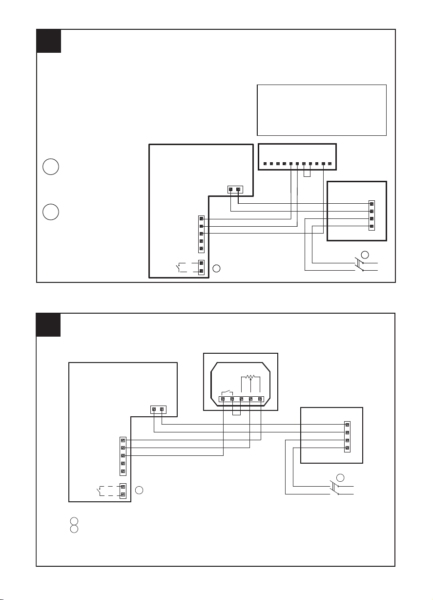
19
1 2 POLES SWITCH (DPST)
1
L
N
2
P
CB
COVER
WIRING TO THE “POTENTIOMETER + ON/OFF” CONTROL BOX (CODE 12826)
N
L
P
0
PI
P10
S1
S2
R2
R1
4
3
L2
N1
DRY CONTACT FOR
ALARM SIGNALLING
(250VAC, max current 3A)
NOTES
1) Don’t remove wire connected between contact “N”
of PCB and contact “3” of terminal block on cover
2) Don’t remove wire connected between contact “L”
of PCB and contact “4” of terminal block on cover
NLN1L1S3S2S1SCBCBNOBNC
CONTROL BOX
LINEO 315 V0 ES
2
PCB Control Port Description
-
--------------------------------------
P
0 = Potentiometer 0V = GND
P
I = Potentiometer Input Signal = 0-10V
P
10 = Potentiometer 10V = +10V
S
1-S2 = dry contact for MAX/MIN speed
R1-R2 = dry contact for optional Alarm
20
WIRING TO AN EXTERNAL POTENTIOMETER TYPE DIN
LINEO 315 V0 ES
1 2 POLES SWITCH (DPST)
2
2
1
L
N
DRY CONTACT FOR ALARM SIGNALLING
(250VAC, max current 3A)
PCB/SCHEDA
COVER/COP ERCHIO
POTENTIOMETER/POTENZIOMETRO
-(GND)+(OUT)Us
R: 10 Kohm
Switch
10A / 12VDC
4A / 250VAC
4
3
L2
N1
NL
P0
PI
P10
S1
S2
R1
R2
NOTES
1) Don’t remove wire connected between contact “N”
of PCB and contact “3” of terminal block on cover
2) Don’t remove wire connected between contact “L”
of PCB and contact “4” of terminal block on cover
50
Page 51

1
2 POLES SWITCH (DPST)
1
L
N
2
3
3
DRY CONTACT FOR ALARM SIGNALLING
(250VAC, max current 3A)
EXTERNAL GENERATOR SIGNAL 0-10V
2
C
OVER
PCB Control Port Description
--------------------------------------P0 = Potentiometer 0V = GND
PI = Potentiometer Input Signal = 0-10V
P10 = Potentiometer 10V = +10V
S1-S2 = dry contact for MAX/MIN speed
R1-R2 = dry contact for optional Alarm
NOTES
1) Don’t remove wire connected between contact “N”
of PCB and contact “3” of terminal block on cover
2) Don’t remove wire connected between contact “L”
of PCB and contact “4” of terminal block on cover
P0
PI
P10
S1
S2
R
2
R1
PCB
G
ND
OUT (0-10V)
4
3
L2
N1
N
L
21
WIRING TO AN EXTERNAL GENERATOR SIGNAL 0-10V
LINEO 315 V0 ES
22
1 2 POLES SWITCH (DPST)
2
4
3
POTENTIOMETER
( FROM 5 KOHM TO 10 KOHM)
WIRING TO AN EXTERNAL POTENTIOMETER
ON/OFF SWITCH (SPST)
DRY CONTACT FOR
ALARM SIGNALLING
(250VAC, max current 3A)
LINEO V0 ES 100, 125, 150, 160, 100Q, 200, 250
1
L
N
2
3
4
P0
PI
P10
S1
S2
N L
R2
R1
PCB
PCB Control Port Description
--------------------------------------P0 = Potentiometer 0V = GND
PI = Potentiometer Input Signal = 0-10V
P10 = Potentiometer 10V = +10V
S1-S2 = dry contact for MAX/MIN speed
R1-R2 = dry contact for optional Alarm
51
Page 52

24
1 2 POLES SWITCH (DPST)
2
WIRING TO THE “POTENTIOMETER + ON/OFF” CONTROL BOX (CODE 12826)
DRY CONTACT FOR
ALARM SIGNALLING
(250VAC, max current 3A)
LINEO V0 ES 100, 125, 150, 160, 100Q, 200, 250
1
L
N
2
CONTROL BOX
PCB
NLN1L1S3S2S1SCBCBNOBNC
P0
PI
P10
S1
S2
R2
R1
N
L
PCB Control Port Description
--------------------------------------P0 = Potentiometer 0V = GND
PI = Potentiometer Input Signal = 0-10V
P10 = Potentiometer 10V = +10V
S1-S2 = dry contact for MAX/MIN speed
R1-R2 = dry contact for optional Alarm
23
1 2 POLES SWITCH (DPST)
2
3
LOW/HIGH S PEED SWITCH
SPST
WIRING TO AN EXTERNAL LOW/HIGH SPEED SWITCH
DRY CONTACT FOR
ALARM SIGNALLING
(250VAC, max current 3A)
1
L
N
2
3
MIN
M
AX
LINEO V0 ES 100, 125, 150, 160, 100Q, 200, 250
P
0
PI
P10
S1
S
2
PCB
N L
R
2
R
1
PCB Control Port Description
--------------------------------------P0 = Potentiometer 0V = GND
PI = Potentiometer Input Signal = 0-10V
P10 = Potentiometer 10V = +10V
S1-S2 = dry contact for MAX/MIN speed
R1-R2 = dry contact for optional Alarm
52
Page 53

1
2 POLES SWITCH (DPST)
2
3
DRY CONTACT FOR ALARM SIGNALLING
(250VAC, max current 3A)
EXTERNAL GENERATOR SIGNAL 0-10V
PCB Control Port Description
--------------------------------------P0 = Potentiometer 0V = GND
PI = Potentiometer Input Signal = 0-10V
P10 = Potentiometer 10V = +10V
S1-S2 = dry contact for MAX/MIN speed
R1-R2 = dry contact for optional Alarm
26
WIRING TO AN EXTERNAL GENERATOR SIGNAL 0-10V
LINEO V0 ES 100, 125, 150, 160, 100Q, 200, 250
1
L
N
2
PCB
N
L
P0
PI
P10
S1
S2
R2
R1
GND
OUT (0-10V)
3
25
WIRING TO THE EXTERNAL POTENTIOMETER TYPE DIN
1 2 POLES SWITCH ( DPST)
1
L
N
P10
P1
R2
R1
S2
S
1
2
2
D
RY CONTACT FOR ALARM SIGNALLING
(
250VAC, max current 3A)
POTENTIOMETER/POTENZIOMETRO
PCB/SCHEDA
-(GND)+(OUT)Us
R: 10 Kohm
S
witch
10A / 12VDC
4A / 250VAC
LN
P0
LINEO V0 ES 100, 125, 150, 160, 100Q, 200,250
53
Page 54

27 27
28 28
29 29
VORTICE LIMITED
Beeches House - Eastern Avenue
Burton on Trent
DE13 0BB
Tel. +44 1283-492949
UNITED KINGDOM
vortice.ltd.uk
sales@vortice.ltd.uk
VORTICE ELETTROSOCIALI S.p.A.
Strada Cerca, 2 - frazione di Zoate
20067 TRIBIANO (MI)
Tel. +39 02-90.69.91
ITALIA
vortice-italy.it
postvendita@vortice-italy.com
VORTICE LATAM S.A.
3er Piso, O
cina 9-B, Edi cio
Meridiano
Guachipelín, Escazú, San José
PO Box 10-1251
Te l +506 2201 6242;
COSTA RICA
vortice-latam.com
info@vortice-latam.com
VORTICE VENTILATION SYSTEM (CHANGZHOU) CO., LTD
Building 19 , No.388 West Huanghe Road, Xinbei District,
Changzhou, Jiangsu Province CAP:213000
CHINA
vortice-china.com
vortice@vortice-china.com
Vortice Elettrosociali S.p.A. si riserva il diritto di apportare tutte le varianti migliorative ai prodotti in corso di vendita.
Vortice Elettrosociali S.p.A. reserves the right to make improvements to products at any time and without prior notice.
La société Vortice Elettrosociali S.p.A. se réserve le droit d'apporter toutes les variations afin d'améliorer ses produits en cours de commercialisation.
Die Firma Vortice Elettrosociali S.p.A. behält sich vor, alle eventuellen Verbesserungsänderungen an den Produkten des Verkaufsangebots vorzunehmen.
Vortice Elettrosociali S.p.A. se reserva el derecho de incorporar todas las mejoras necesarias a los productos en fase de venta.
Vortice Elettrosociali S.p.A.
Page 55

555657
Page 56

Page 57

Page 58

A
TAGLIANDO INTERVENTO IN GARANZIA
CERTIFICATE OF WORK PERFORMED UNDER GUARANTEE
COUPON INTERVENTION SOUS GARANTIE
DATA INTERVENTO
DATE OF WORK - DATE INTERVENTION
TIMBRO CENTRO ASSISTENZA
TAGLIANDO INTERVENTO IN GARANZIA
CERTIFICATE OF WORK PERFORMED UNDER GUARANTEE
COUPON INTERVENTION SOUS GARANTIE
DATA INTERVENTO
DATE OF WORK - DATE INTERVENTION
TIMBRO CENTRO ASSISTENZA
STAMP OF TECHNICAL ASSISTANCE CENTRE - CACHET SERVICE APRES-VENTE
TAGLIANDO INTERVENTO IN GARANZIA
CERTIFICATE OF WORK PERFORMED UNDER GUARANTEE
COUPON INTERVENTION SOUS GARANTIE
DATA INTERVENTO
DATE OF WORK - DATE INTERVENTION
TIMBRO CENTRO ASSISTENZA
TAGLIANDO INTERVENTO IN GARANZIA
CERTIFICATE OF WORK PERFORMED UNDER GUARANTEE
COUPON INTERVENTION SOUS GARANTIE
DATA INTERVENTO
DATE OF WORK - DATE INTERVENTION
TIMBRO CENTRO ASSISTENZA
B
C
D
STAMP OF TECHNICAL ASSISTANCE CENTRE - CACHET SERVICE APRES-VENTE
STAMP OF TECHNICAL ASSISTANCE CENTRE - CACHET SERVICE APRES-VENTE
STAMP OF TECHNICAL ASSISTANCE CENTRE - CACHET SERVICE APRES-VENTE
Page 59

ITALIA
CONDIZIONI DI GARANZIA
VORTICE ELETTROSOCIALI SPA garantisce i suoi
p
rodotti per 2 anni dalla data dell’acquisto, che deve
essere c omprova ta da idoneo documento fiscale (scontrino
o fattura), rilasciato dal venditore. Nel suddetto periodo di
g
aranzia VORTICE ELETTROSOCIALI SPA si impegna,
dopo aver effettuato le opportune valutazioni tecniche, a
riparare o a sostituire gratuitamente le parti
dell’apparecch
io che risultassero affette da difetti di
f
abbricazione. La presente garanzia, da attivare nei modi
e nei termini di seguito indicati, lascia impregiudicati i
diritti derivanti al consumatore dalla applicazione del D.
l
gs. 24/2002.Tali diritti, conformemente alla legge,
potranno essere fatti valere esclusivamente nei confronti
del proprio venditore.
La presente garanzia è valida su tutto il territorio i
taliano.
Modalità e condizioni di attivazione della garanzia
Gli interventi in garanzia (riparazioni o sostituzioni del
prodotto ovvero delle parti difettose) saranno eseguiti
presso uno dei Centri di Assistenza Tecnica autorizzati da
VORTICE ELETTROSOCIALI SPA, il cui indirizzo è
disponibile sull’elenco telefonico alfabetico o contattando
il numero verde 800.555.777.
La prestazione eseguita in garanzia no
n prolunga il
periodo della garanzia. Pertanto, incaso di sostituzione
del prodotto o di un suo componente, sul bene o sul
singolo componente fornito in sostituzione non decorre
un nuovo periodo di garanzia ma si deve tener conto
della data di acquisto del prodotto originario.
UK AND IRELAND
CONDITIONS OF WARRANTY
This guarantee is offered as an extra benefit and
d
oes not affect your legal rights. All electrical
appliances produced by
VORTICE ELETTROSOCIALI SPA are guaranteed by
t
he Company for 2 years against faulty material or
workmanship. If any part is found to be defective in this
way within the first twentyfour months from the date of
purchase or hire purchase agreement, we, or our
authori
sed service agents, will replace or at our option
repair that part without any charge for materials or labour
or transportation, provided that the appliance has been
u
sed only in accordance with the instructions provided
with each appliance and has been not connected to an
unsuitable electricity supply, or subjected to misuse,
neglect or damage or modified or repaired by any person
not authorised by us.
The correct electricity supply
voltage is shown on the rating plate attached to the
appliance. This guarantee is normally available only to
the original purchaser of theappliance, but the Company
will consider written applications for transfer. Should any
defect arise in any Vortice product and a claim under
guarantee become necessary, the appliance should be
carefully packed and returned to your approve
d Vortice
stockist. This po rtion of the g uara ntee sho uld be attach ed
to the appliance.
ITALIA
Spedire la garanzia in busta
chiusa a:
Vortice Elettrosociali S.p.A.
Strada Cerca 2
Frazione di Zoate
20067 Tribiano Milano.
UK-IRELAND
Send the guarantee
in sealed envelope to:
Vortice Limited
Beeches House
Eastern Avenue
Burton on Trent
DE13 0BB United Kingdom
OTHER COUNTRIES
Please send the guarantee to the
retailer’s address in the country where
the appliance has been purchased.
Autorizzo
VORTICE ELETTROSOCIALI SPA
ad inserire i miei dati nelle sue
liste e a comunicarli a terzi per
l’invio di materiale pubblicitario
ed informativo. In ogni momento,
a norma dell’art. 13 legge
675/96, potrò avere accesso ai
miei dati, chiederne la modifica
o la cancellazione oppure
oppormi al loro utilizzo scrivendo
a:
Vortice Elettrosociali S.p.A.
Responsabile
trattamento dati
- Strada Cerca, 2
- Frazi
one di Zoate -
20067 Tribiano (MI).
I authorize
VORTICE LTD.
to include my personal
details within their
database, which they use,
via a third party for the
despatch of advertising
material, at any time, in
accordance with the
regulations in force within
my country. I can have
access to my details and
can request changes, or
prohibit the usage of my
details.This will be done
by addressing my request
directly to:
V
ortice Limited
Beeches House
Eastern Avenue
Burton on Trent
DE13 0BB United
Kingdom.
I authorize
VORTICE ELETTROSOCIALI SPA
and its local distributors to
include my personal details
within their database and they
can use it through a third party
for the despatch of advertising
material. At any time, in
accordance with the regulations
in force within my country. I can
have access to details and can
ask to make cha
nges, or
prohibit the usage of my
details.This will be done by
addressing my request directly
to the headquarters of the local
distributor where the appliance
has been bought.
I do not authorize
(please tick if required)
Non autorizzo
(barrare se interessa)
I do not authorize
(please tick if required)
Page 60
ANNI
YEARS
2
1
G
ARANZIA - GUARANTEE - GARANTIE
DA CONSERVARE
T
O BE RETAINED
A
CONSERVER
P
er poter usufruire della garanzia il cliente deve compilare e rispedire a
VORTICE ELETTROSOCIALI SPA, entro 8 giorni dall’acquisto, la “Parte
2
” del tagliando di garanzia, all’indirizzo e con le modalità in tale parte
riportate.
L
a “Pa rte 1” de l taglia ndo di garanzi a deve es sere con serva ta e pres entata,
unitamente al documento fiscale (scontrino o fattura) rilasciato dal
v
enditore al momento dell’acquisto, al Centro di Assistenza autorizzato di
V
ORTICE ELETTROSOCIALI SPA, che dovrà eseguire l’intervento in
g
aranzia.
This warranty must be attached to the appliance should it need to be
returned for servicing.
N.B. Guarantee is only valid if all details are completed correctly.
ATTENTION: pour bénéficier de la garantie, le présent certificat doit
o
bligatoirement acc ompagner l’appareil p résumé déf ectueux. Le certifica t
d
oit porter le cachet du revendeur et la date d’achat.
A
defaut, la garantie sera comptée à partir de la date de sortie d’usine.
Esclusioni
L
a presente garanzia non copre:
•
Le rotture provocate dal trasporto.
• I difetti o guasti derivanti da uso non corretto o improprio da parte del cliente.
• I difetti derivanti dal mancato rispetto delle avvertenze e condizioni d’uso indicate nel libretto di istruzioni ed uso
allegato al prodotto.
• I difetti derivanti da non corretta installazione ovvero da una installazione effettuata senza rispettare quanto previsto
nel relativo capitolo del libretto di istruzioni ed uso.
• I guasti derivanti da un errato allacciamento alla rete di alimentazione elettrica o per tensione di alimentazione
diversa da quella prevista per l’apparecchio, ovvero diversa dal limite stabilito dalle norme CEI (+/- 10% del valore
nominale).
La presente garanzia non copre, inoltre, gli eventuali difetti derivanti da una cattiva manutenzione ovvero da
interventi effettuati da personale non qualificato o da terzi non autorizzati.
T
IMBRO RIVENDITORE
stamp of supplier
cacher du vendeur
DATA SPEDIZIONE
Mailing date - Date d’expédition
DATA ACQUISTO
Purchase date - Date d’achat
CONF.
COLL.
DATI UTENTE / CUSTOMER DATA / COORDONNÉES DE L’UTILISATEUR
nome / name / nom _____________________________________________________
cognome / surname / prenom _____________________________________________
via / street / rue ________________________________________________________
cap / post code / code postal ______________________________________________
città / town ____________________________________________________________
Dichiaro di aver preso atto delle condizioni di garanzia specificate sul certificato in mio possesso e autorizzo la gestione dei miei dati personali (v.
retro).
I have read and understood the terms and conditions of this guarantee and I authorize the processing of my personal details (see overleaf).
Suivant les conditions de garantie définies par le certificat en ma possession j’autorise l’utilisation de mes coordonnées (voir au verso).
Firma / Signature / Signature ______________________________________________
2
GARANZIA - GUARANTEE - GARANTIE
DA SPEDIRE (entro 8 giorni dall’acquisto)
TO SEND (within 8 days from date of purchase)
A RETOURNER (dans les 8 jours après l’achat)
TIMBRO RIVENDITORE
stamp of supplier
cacher du vendeur
ANNI
YEARS
2
DATA ACQUISTO
Purchase date - Date d’achat
DA
T
A
SP
ED
IZI
O
N
E
Ma
ilin
g d
ate
- D
ate
d’
ex
pé
dit
ion
 Loading...