

Vortice LINEO 125 V0 ES, LINEO 200 V0 ES, LINEO 100 Q V0 ES, LINEO 150 V0 ES, LINEO 250 V0 ES Instruction Booklet
...Page 1
Libretto istruzioni
Instruction booklet
Notice d’emploi et d’entretien
Betriebsanleitung
Manual de instrucciones
LINEO 100 V0 ES, 100 Q V0 ES
125 V0 ES, 150 V0 ES, 160 V0 ES
200 V0 ES, 250 V0 ES, 315 V0 ES
Instructieboekje
Bruksanvisning
Käyttöohjeet
Manual de instrucţiuni
Инструкция по эксплуатации
COD. 5.471.084.979 29/03/2018
Page 2

Prima di usare il prodotto leggere attentamente
le istruzioni contenute nel presente libretto.
Vortice non potrà essere ritenuta responsabile
per eventuali danni a persone o cose causati
dal mancato rispetto delle indicazioni di seguito
elencate, la cui osservanza assicurerà invece la
durata e l’affidabilità, elettrica e meccanica,
dell’apparecchio.
Conservare sempre questo libretto istruzioni.
Read the instructions contained in this booklet
carefully before using the appliance.
Vortice cannot assume any responsibility for da-
mage to property or personal injury resulting
from failure to abide by the instructions given in
this booklet.
Following these instructions will ensure a long
service life and overall electrical and mechanical
reliability.
Keep this instruction booklet in a safe place.
Indice IT
Descrizione e impiego . . . . . . . . . . . . . . . . . . . . . . 4
Sicurezza . . . . . . . . . . . . . . . . . . . . . . . . . . . . . . . . 4
Applicazioni tipiche . . . . . . . . . . . . . . . . . . . . . . . . 4
Installazione . . . . . . . . . . . . . . . . . . . . . . . . . . . . . . 4
Configurazione iniziale . . . . . . . . . . . . . . . . . . . . . . 5
Ripristino valori nominali . . . . . . . . . . . . . . . . . . . . 6
Funzionamento. . . . . . . . . . . . . . . . . . . . . . . . . . . . 6
Manutenzione / Pulizia . . . . . . . . . . . . . . . . . . . . . 6
Figure . . . . . . . . . . . . . . . . . . . . . . . . . . . . . . . . . . 34
Table of Contents EN
Description and operation . . . . . . . . . . . . . . . . . . . 7
Safety . . . . . . . . . . . . . . . . . . . . . . . . . . . . . . . . . . . 7
Typical applications . . . . . . . . . . . . . . . . . . . . . . . . 7
Installation . . . . . . . . . . . . . . . . . . . . . . . . . . . . . . . 7
Initial configuration. . . . . . . . . . . . . . . . . . . . . . . . . 7
Restoring nominal values . . . . . . . . . . . . . . . . . . . . 9
Operation . . . . . . . . . . . . . . . . . . . . . . . . . . . . . . . . 9
Maintenance / Cleaning . . . . . . . . . . . . . . . . . . . . . 9
Figures . . . . . . . . . . . . . . . . . . . . . . . . . . . . . . . . . 34
Avant d'utiliser le produit, lire attentivement les
instructions contenues dans cette notice.
La société Vortice ne pourra être tenue pour
responsable des dommages éventuels causés
aux personnes ou aux choses par suite du non-
respect desinstructions ci-dessous.
Le respect de toutes les indications reportées
dans ce livret garantira une longue durée de vie
ainsi que la fiabilité électrique et mécanique de
l'appareil.
Conserver toujours ce livret d'instructions.
Vor Installation und Anschluss dieses Produkts
müssen die vorliegenden Anleitungen
aufmerksam durchgelesen werden.
Vortice kann nicht für Personen- oder Sachschä-
den zur Verantwortung gezogen
werden, die auf eine Nichtbeachtung der Hin-
weise in dieser Betriebsanleitung
zurückzuführen sind. Befolgen Sie alle Anweisungen, um eine lange Lebensdauer sowie die
elektrische und mechanische Zuverlässigkeit des
Geräts zu gewährleisten.
Diese Betriebsanleitung ist gut aufzubewahren.
Antes de utilizar el producto, hay que leer atenta-
mente las instrucciones de este folleto
Vortice no es responsable de los eventuales
daños ocasionados a personas o cosas como re-
sultado del incumplimiento de las indicaciones
de este manual, las cuales garantizan la durabilidad y fiabilidad eléctrica y mecánica del aparato.
Conservar este manual de instrucciones.
Index FR
Description et mode d’employ . . . . . . . . . . . . . . 10
Sécurité . . . . . . . . . . . . . . . . . . . . . . . . . . . . . . . . 10
Applications typiques. . . . . . . . . . . . . . . . . . . . . . 10
Installation . . . . . . . . . . . . . . . . . . . . . . . . . . . . . . 10
Configuration initiale. . . . . . . . . . . . . . . . . . . . . . . 10
Rétablissement des valeurs nominales . . . . . . . . 12
Fonctionnement . . . . . . . . . . . . . . . . . . . . . . . . . . 12
Entretien / Nettoyage . . . . . . . . . . . . . . . . . . . . . . 12
Figures . . . . . . . . . . . . . . . . . . . . . . . . . . . . . . . . . 34
Inhaltsverzeichnis DE
Beschreibung und Gebrauch . . . . . . . . . . . . . . . 13
Sicherheit . . . . . . . . . . . . . . . . . . . . . . . . . . . . . . . 13
Typische Anwendungsarten . . . . . . . . . . . . . . . . . 13
Einstellung . . . . . . . . . . . . . . . . . . . . . . . . . . . . . . 14
Anfangskonfiguration . . . . . . . . . . . . . . . . . . . . . . 14
Wiederherstellen der Nennwerte . . . . . . . . . . . . . 15
Betrieb . . . . . . . . . . . . . . . . . . . . . . . . . . . . . . . . . 15
Wartung / Reinigung. . . . . . . . . . . . . . . . . . . . . . . 15
Abbildungen . . . . . . . . . . . . . . . . . . . . . . . . . . . . . 34
Índice ES
Descripción y uso . . . . . . . . . . . . . . . . . . . . . . . . 16
Seguridad. . . . . . . . . . . . . . . . . . . . . . . . . . . . . . . 16
Aplicaciones típicas . . . . . . . . . . . . . . . . . . . . . . . 16
Instalación . . . . . . . . . . . . . . . . . . . . . . . . . . . . . . 16
Configuración inicial. . . . . . . . . . . . . . . . . . . . . . . 17
Restablecimiento de los valores nominales. . . . . 18
Funcionamiento . . . . . . . . . . . . . . . . . . . . . . . . . . 18
Mantenimiento / Limpieza . . . . . . . . . . . . . . . . . . 18
Figuras . . . . . . . . . . . . . . . . . . . . . . . . . . . . . . . . . 34
2
Page 3

Lees deze handleiding aandachtig door alvorens
het product te plaatsen en aan te sluiten.
Vortice kan niet aansprakelijk worden gesteld
voor eventuele schade aan personen of zaken,
ontstaan als gevolg van het niet in acht nemen
van de aanwijzingen die hierna vermeld zijn,
het opvolgen hiervan zal de elektrische en
mechanische betrouwbaarheid van het
apparaat verzekeren.
Bewaar dit instructieboekje altijd zorgvuldig.
Innan produkten används läs noggrant
anvisningarna i den här bruksanvisningen.
Vortice kan ej hållas ansvarig för eventuella
skador på personer eller föremål som orsakats
avatt nedan listade anvisningar inte har iakttagits,
vilka om de däremot iakttas garanterar
apparatens elektriska och mekaniska pålitlighet.
Bevara därför alltid denna bruksanvisning för
framtida bruk.
Inhoud NL
Beschrijving en gebruik . . . . . . . . . . . . . . . . . . . . 19
Veiligheid . . . . . . . . . . . . . . . . . . . . . . . . . . . . . . . 19
Karakteristieke toepassingen. . . . . . . . . . . . . . . . 19
Installatie . . . . . . . . . . . . . . . . . . . . . . . . . . . . . . . 20
Eerste configuratie . . . . . . . . . . . . . . . . . . . . . . . . 20
Nominale waarden resetten . . . . . . . . . . . . . . . . . 21
Werking . . . . . . . . . . . . . . . . . . . . . . . . . . . . . . . . 21
Onderhoud / reiniging . . . . . . . . . . . . . . . . . . . . . 21
Afbeelding . . . . . . . . . . . . . . . . . . . . . . . . . . . . . . 34
Innehållsförteckning SV
Beskrivning och användning . . . . . . . . . . . . . . . . 22
Säkerhet . . . . . . . . . . . . . . . . . . . . . . . . . . . . . . . . 22
Typiska tillämpningar . . . . . . . . . . . . . . . . . . . . . . 22
Installation . . . . . . . . . . . . . . . . . . . . . . . . . . . . . . 22
Startkonfigurering. . . . . . . . . . . . . . . . . . . . . . . . . 23
Återställning av nominella värden . . . . . . . . . . . . 24
Funktion . . . . . . . . . . . . . . . . . . . . . . . . . . . . . . . . 24
Underhåll/rengöring . . . . . . . . . . . . . . . . . . . . . . . 24
Figurer . . . . . . . . . . . . . . . . . . . . . . . . . . . . . . . . . 34
Lue nämä ohjeet huolellisesti ennen kuin alat
käyttää laitetta.
Vortice ei vastaa mahdollisista henkilö- tai
esinevahingoista, jotka ovat seurausta tämän
käyttöohjekirjan ohjeiden noudattamisen
laiminlyönnistä. Noudata kaikkia tässä mainittuja
ohjeita varmistaaksesi laitteen sähköisen ja
mekaanisen kestävyyden ja luotettavan
toiminnan.
Säilytä tämä käyttöohjekirja tallessa tulevaa
tarvetta varten.
Înainte de a utiliza produsul, citiţi cu atenţie
instrucţiunile din acest manual.
Firma Vortice nu poate fi considerată
responsabilă pentru eventualele pagube aduse
persoanelor sau bunurilor, cauzate de
nerespectarea indicaţiilor de mai jos;
în schimb, respectarea acestora va asigura o
durată lungă de viaţă a aparatului şi fiabilitatea
sa,electrică şi mecanică.
Păstraţi cu grijă acest manual de instrucţiuni.
Перед началом эксплуатации изделия
внимательно прочитайте указания,
приведенные в настоящей инструкции.
Фирма Vortice не может считаться
ответственной за травмы или
материальный ущерб, которые могут
быть вызваны несоблюдением положений
нижеприведенных указаний, в то время как
их выполнение явится гарантией
длительного срока службы и механической
и электрической надежности устройства.
Сохраняйте настоящую инструкцию.
Hakemisto FI
Laitteen kuvaus ja käyttö . . . . . . . . . . . . . . . . . . . 25
Turvallisuus. . . . . . . . . . . . . . . . . . . . . . . . . . . . . . 25
Tyypilliset käyttökohteet. . . . . . . . . . . . . . . . . . . . 25
Asennus . . . . . . . . . . . . . . . . . . . . . . . . . . . . . . . . 25
Startkonfigurering. . . . . . . . . . . . . . . . . . . . . . . . . 25
Nimellisarvojen palauttaminen . . . . . . . . . . . . . . . 27
Toiminta . . . . . . . . . . . . . . . . . . . . . . . . . . . . . . . . 27
Huolto / Puhdistus . . . . . . . . . . . . . . . . . . . . . . . . 27
Kuvat . . . . . . . . . . . . . . . . . . . . . . . . . . . . . . . . . . 34
Cuprins RO
Descrierea şi utilizarea . . . . . . . . . . . . . . . . . . . . . 28
Siguranţa . . . . . . . . . . . . . . . . . . . . . . . . . . . . . . . 28
Aplicaţii tipice . . . . . . . . . . . . . . . . . . . . . . . . . . . . 28
Instalarea . . . . . . . . . . . . . . . . . . . . . . . . . . . . . . . 28
Configuraţia iniţială. . . . . . . . . . . . . . . . . . . . . . . . 29
Resetarea valorilor nominale . . . . . . . . . . . . . . . . 30
Funcţionarea . . . . . . . . . . . . . . . . . . . . . . . . . . . . . 30
Întreţinerea / Curăţarea . . . . . . . . . . . . . . . . . . . . 30
Figuri. . . . . . . . . . . . . . . . . . . . . . . . . . . . . . . . . . . 34
Оглавление RU
Описание изделия и способ его применения . 31
Правила техники безопасности. . . . . . . . . . . . . 31
Обычные виды применения. . . . . . . . . . . . . . . . 32
Установка . . . . . . . . . . . . . . . . . . . . . . . . . . . . . . 32
Первоначальная настройка . . . . . . . . . . . . . . . . 32
Восстановление номинальных значений . . . . . 33
Функционирование . . . . . . . . . . . . . . . . . . . . . . . 33
Техобслуживание/Чистка . . . . . . . . . . . . . . . . . 33
Иллюстрации . . . . . . . . . . . . . . . . . . . . . . . . . . . 34
3
Page 4
Avvertenza:
questo simbolo indicacheènecessario
prendere precauzioni per evitare danni al prodotto
!
Attenzione:
questo simbolo indicacheènecessario
prendere precauzioni per evitare danni all’utente
!
ITALIANO
Descrizione ed impiego
L’apparecchio da lei acquistato è un aspiratore
elicocentrifugo per l’espulsione dell’aria in condotto
di ventilazione. L’apparecchio è costruito in resina
termoplastica autoestinguente V0, è protetto contro
gli spruzzi d’acqua ed è dotato di motore a due
velocità brushless a controllo elettronico, con
possibilità di regolazione dei valori di velocità minima
e massima.
Sicurezza
• Non usare questo prodotto per una funzione
differente da quella esposta nel presente libretto.
• Dopo aver tolto il prodotto dall’imballo, assicurarsi
della sua integrità; nel dubbio rivolgersi subito ad un
Centro Assistenza Tecnica autorizzato Vortice. Non
lasciare parti dell’imballo alla portata di bambini o
persone diversamente abili.
• L’uso di qualsiasi apparecchio elettrico comporta
l’osservanza di alcune regole fondamentali, tra le
quali:
- non toccarlo con mani bagnate o umide;
- non toccarlo a piedi nudi;
- non consentirne l’uso a bambini o persone
diversamente abili non sorvegliate.
• Questo apparecchio non è da intendersi adatto
all'uso da parte di persone (inclusi bambini) con
ridotte capacità fisiche, sensoriali o mentali, o
comunque prive di esperienza e conoscenza, a
meno che siano sorvegliate o preventivamente
istruite riguardo al suo uso da persona responsabile
della loro sicurezza. I bambini dovrebbero essere
sorvegliati per assicurarsi che non giochino con
l'apparecchio.
• Riporre l’apparecchio lontano da bambini e da
persone diversamente abili nel momento in cui si
decide di scollegarlo dalla rete elettrica e di non
utilizzarlo più.
• Non utilizzare l’apparecchio in presenza di sostanze
o vapori infiammabili come alcool, insetticidi,
• Non apportare modifiche di alcun genere
all’apparecchio.
• Non lasciare l’apparecchio esposto ad agenti
atmosferici (pioggia, sole, ecc.).
• Non appoggiare oggetti sull’apparecchio.
• Verificare periodicamente l’integrità
dell’apparecchio. In caso di imperfezioni non
utilizzarlo e contattare subito un Centro Assistenza
Tecnica autorizzato Vortice.
• In caso di cattivo funzionamento e/o guasto
dell'apparecchio rivolgersi subito ad un Centro di
Assistenza autorizzato Vortice e richiedere, per
l’eventuale riparazione, l'uso di ricambi originali
Vortice.
4
• Se l’apparecchio cade o riceve forti colpi farlo
verificare subito presso un Centro di Assistenza
Tecnica autorizzato Vortice.
• L’impianto elettrico a cui è collegato l’apparecchio
deve essere conforme alle norme vigenti.
• Collegare l’apparecchio alla rete di
alimentazione/presa elettrica solo se la portata
dell’impianto/presa è adeguata alla sua potenza
massima. In caso contrario rivolgersi subito a
personale professionalmente qualificato.
• Per l’installazione occorre prevedere un interruttore
onnipolare con distanza di apertura dei contatti
uguale o superiore a 3 mm.
• Spegnere l'interruttore generale dell'impianto
quando: a) si rileva un'anomalia di funzionamento;
b) si decide di eseguire una manutenzione di pulizia
esterna; c) quando si decide di non utilizzarlo per
periodi prolungati.
• E’ indispensabile assicurare il necessario rientro
dell’aria nel locale per garantire il funzionamento del
prodotto. Nel caso in cui nello stesso locale sia
installato un apparecchio funzionante a
combustibile (scaldacqua, stufa a metano, ecc.)
non del tipo stagno, assicurarsi che il rientro d’aria
garantisca anche la perfetta combustione di tale
apparecchio.
• L’apparecchio non può essere utilizzato come
attivatore di scaldabagni, stufe, ecc. né deve
scaricare in condotti d’aria calda
• L’apparecchio deve scaricare in condotto singolo
(utilizzato unicamente da questo prodotto).
• Non coprire e non ostruire le due griglie di
aspirazione e mandata dell’apparecchio, in modo
da assicurare l'ottimale passaggio dell'aria.
• Le bocche di mandata e di aspirazione del prodotto
devono essere sempre collegate ad un condotto.
• La temperatura ambiente massima per il
funzionamento dell’apparecchio è di 50° C.
• La protezione dalla sovratemperature e dal
sovraccarico è assicurata dal fusibile e
dall’elettronica di comando.
• I dati elettrici della rete devono corrispondere a
quelli riportati in targa A . (Fig.A)
La targa B riporta i dati secondo regolamento
n.327/2011 UE. (solo mod. 315 ES, Fig.A)
Applicazioni tipiche
Figg. 1- 2;
Quando l’apparecchio viene installato ad un’altezza
inferiore a 2,3 m dal suolo e la lunghezza delle
tubazioni connesse in aspirazione e mandata lo
richiede, è opportuno montare dispositivi atti a
prevenire il rischio di contatti con la girante.
Installazione
Figg 3 ÷ 26.
Fig.3: E = Targa direzione flusso aria; C=Aspirazione;
D= Mandata;
Page 5
ITALIANO
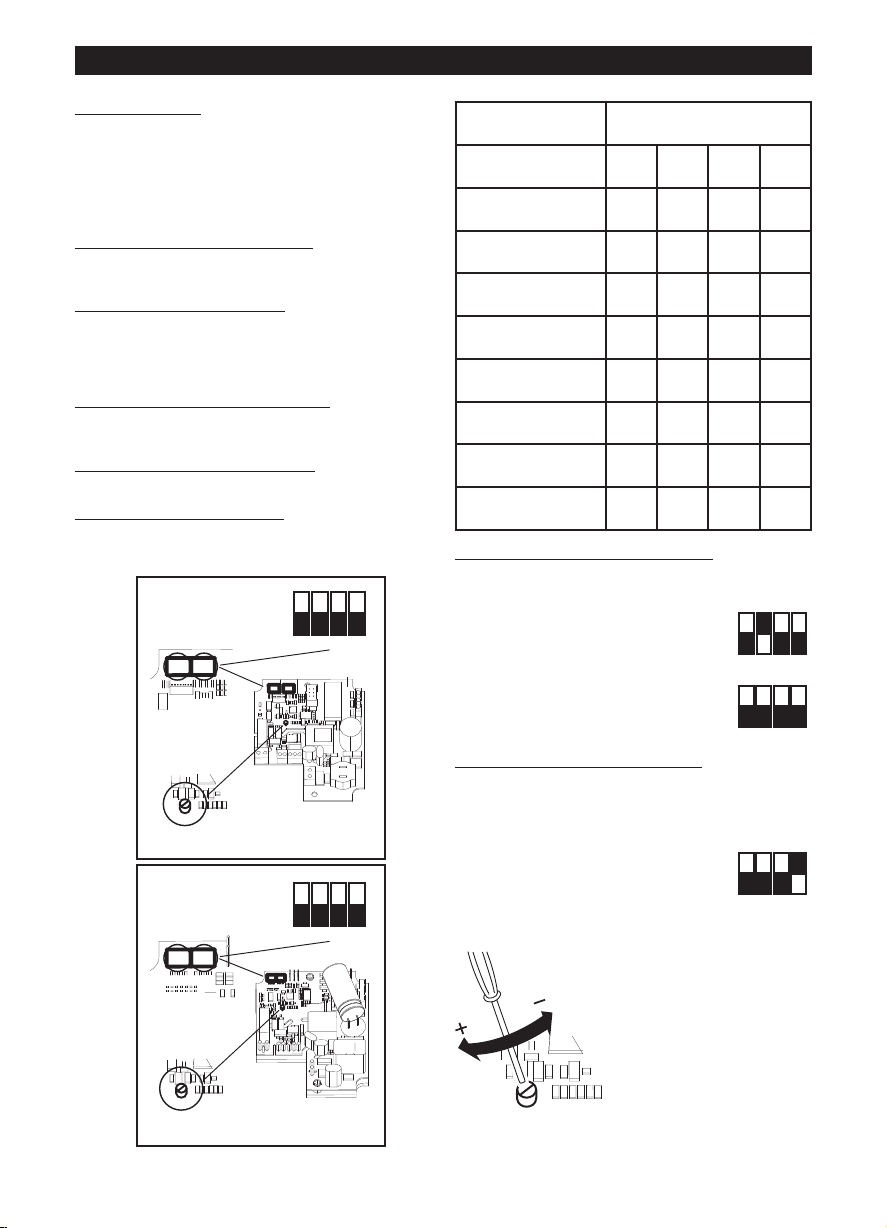
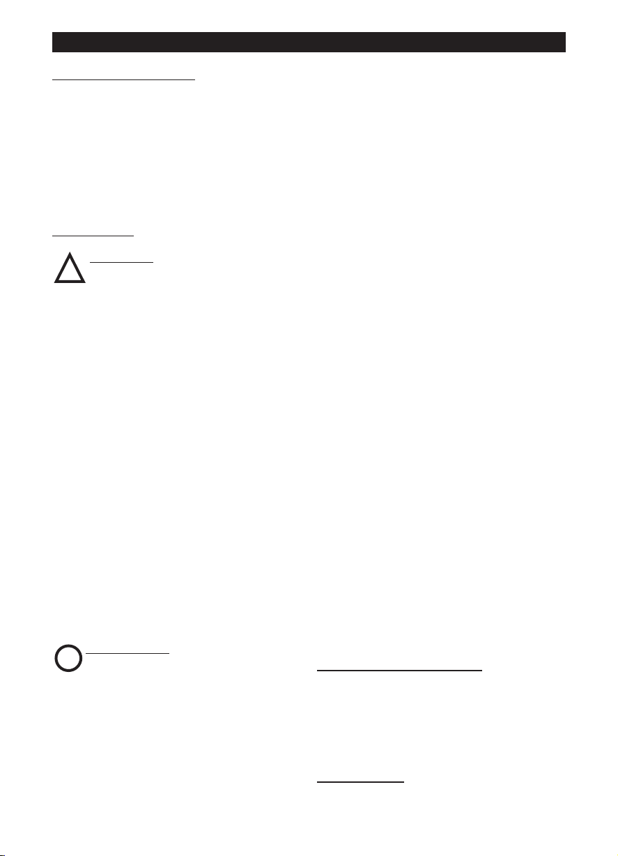
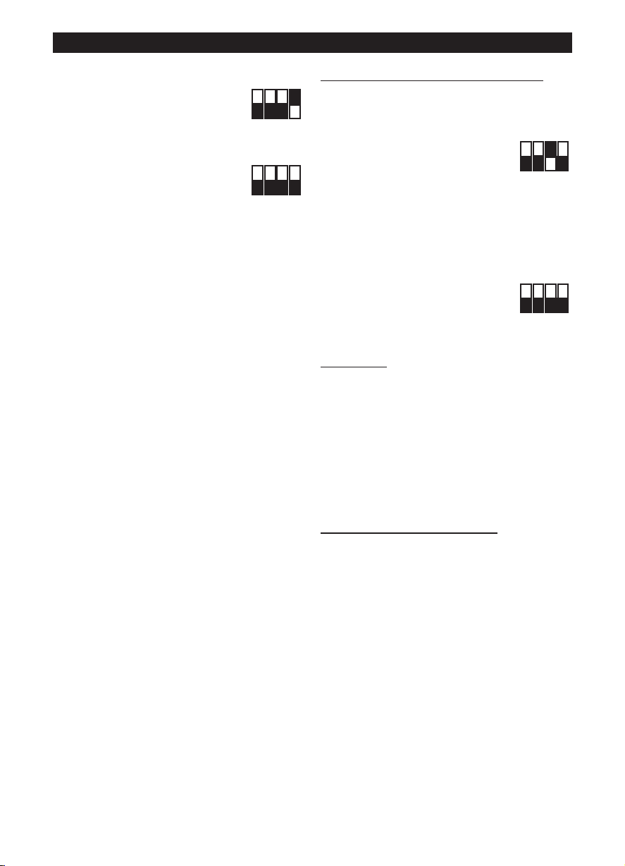
ON
1 2 3 4
OFF
DIPSWITCH
TRIMMER
12
SW 1 : MODEL
SW 2 : SETUP
ON
1 2 3 4
OFF
DIPSWITCH
12
SW 1 : MODEL
SW 2 : SETUP
TRIMMER
ON
1 2 3 4
OFF
ON
1 2 3 4
OFF
ON
1 2 3 4
OFF
Configurazione iniziale
L’installatore deve configurare il funzionamento
dell’apparecchio seguendo i passi descritti più avanti.
Selezione del modello del prodotto
Questa fase è eseguita in fabbrica, le istruzioni
riportate nel presente libretto possono essere utili
solo nel caso sia necessario ripristinare la situazione
in seguito a manomissioni accidentali del dip switch.
Selezione della modalità di funzionamento
seguito. Sono previste due modalità: a due velocità
V1 e V2, selezionabili tramite interruttore esterno,
oppure con velocità regolabile tramite potenziometro
esterno.
Impostazione dei valori di V1 e V2
modalità di funzionamento a due velocità)
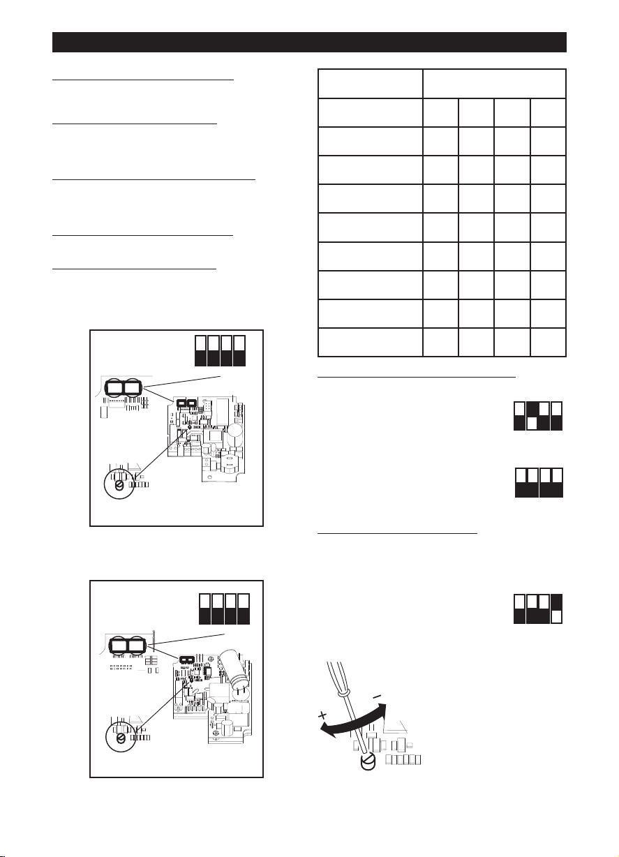
Selezione del modello del prodotto
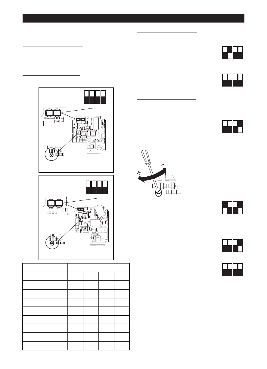
La selezione del modello si effettua tramite
l’impostazione del dip switch SW1 indicato in figura e
come descritto nella seguente tabella.
LINEO 100 Q V0 ES - LINEO 200 V0 ES
LINEO 250 V0 ES, LINEO 315 V0 ES
: vedi nel seguito.
: vedi nel
(nel caso di
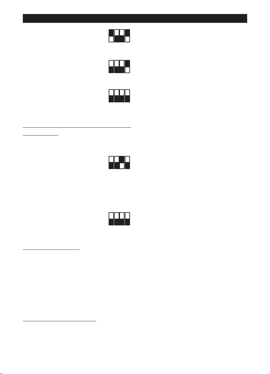
Modello SW1
Int.1 Int.2 Int.3 Int.4
LINEO 100 Q V0 ES OFF OFF OFF OFF
LINEO 100 V0 ES OFF OFF OFF ON
LINEO 125 V0 ES OFF OFF ON OFF
LINEO 150 V0 ES OFF OFF ON ON
LINEO 160 V0 ES OFF ON OFF OFF
LINEO 200 V0 ES OFF ON OFF ON
LINEO 250 V0 ES OFF ON ON OFF
LINEO 315 V0 ES OFF ON ON ON
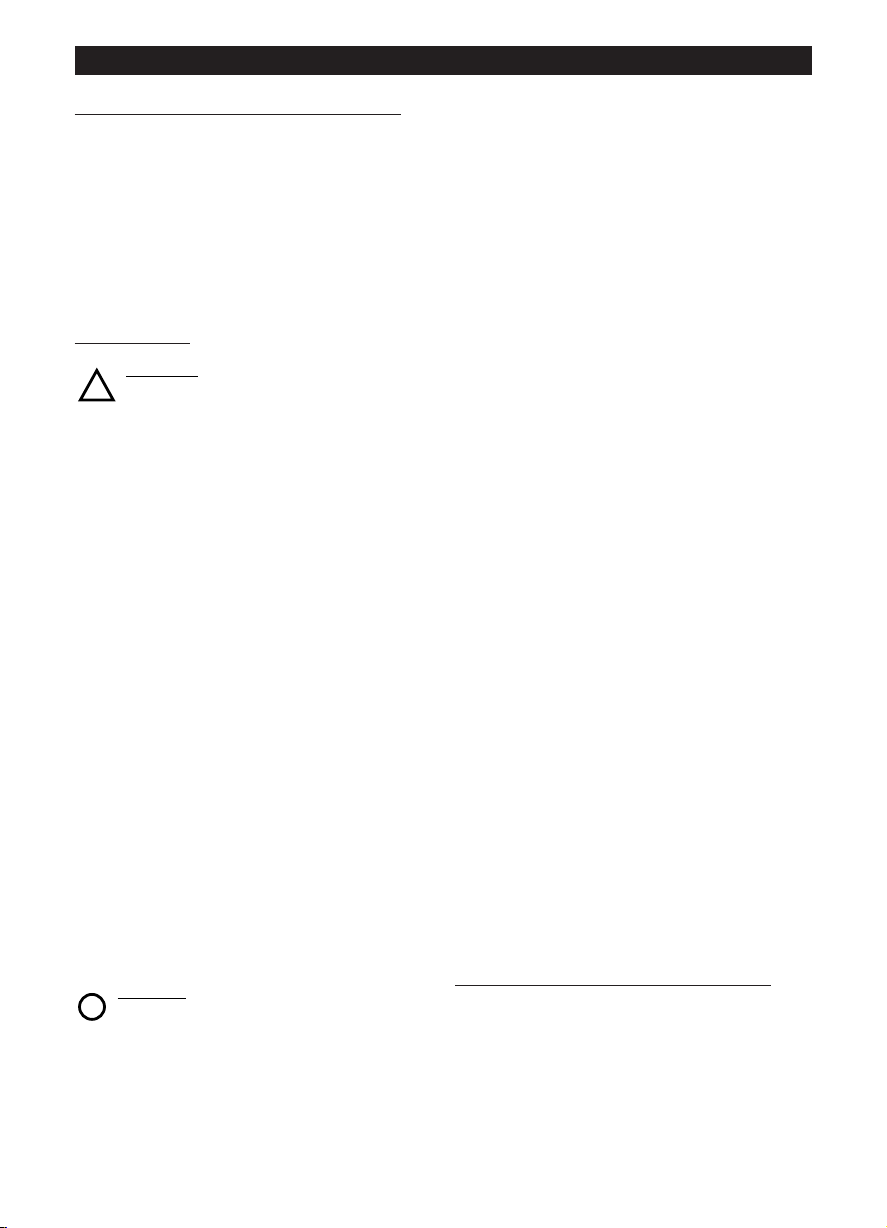
Selezione della modalità di funzionamento
Modalità a due velocità:
togliere l’alimentazione elettrica
impostare sul dip-switch SW2
indicato in figura:
Int.2=ON; Int.3=OFF
Int.4=OFF
Modalità a velocità regolabile:
togliere l’alimentazione elettrica
impostare sul dip-switch SW2
indicato in figura:
Int.2=OFF; Int.3=OFF
Int.4=OFF
Impostazione dei valori di V1 e V2
L’apparecchio esce dalla fabbrica con impostazioni
nominali di default V1=V
E’ possibile regolare i valori di V1 e V2 operando
come segue:
- togliere l’alimentazione elettrica
- impostare sul dip-switch SW2
indicato in figura:
Int.1=OFF
Int.4=ON
- fornire l’alimentazione elettrica. Il motore si porta
automaticamente alla velocità V1temp
, V2=V
MIN
MAX
- agire sul trimmer (vedi
figura) per regolare V1temp
sul valore desiderato,
compreso tra V1nom e la V2
memorizzata – 100Rpm
5
Page 6
ITALIANO
ON
1 2 3 4
OFF
ON
1 2 3 4
OFF
ON
1 2 3 4
OFF
ON
1 2 3 4
OFF
ON
1 2 3 4
OFF
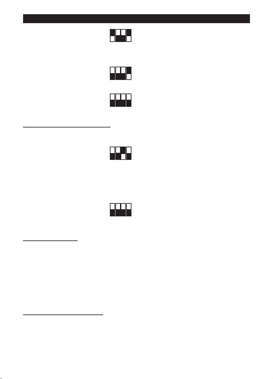
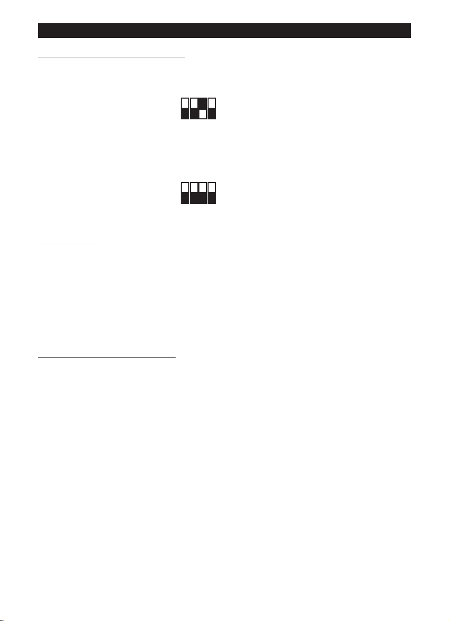
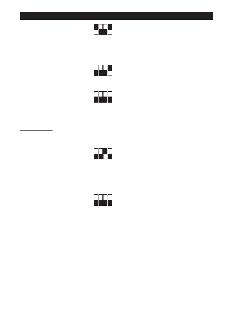
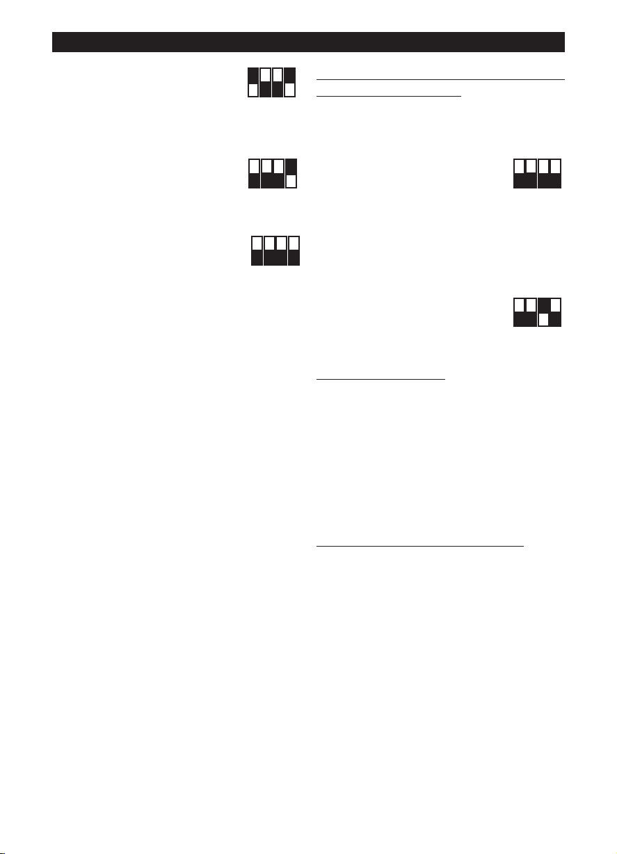
- impostare Int.1=ON. Ciò produce
due effetti:
il valore V1temp viene
memorizzato come nuovo V1;
il motore si porta automaticamente alla V2temp
- agire sul trimmer (vedi figura) per regolare V2temp
sul valore desiderato, compreso tra la V1
memorizzata + 100Rpm e Vmax
- impostare Int.1=OFF. Ciò produce
due effetti:
il valore V2temp viene
memorizzato come nuovo V2;
il motore si porta automaticamente alla V1temp
- togliere l’alimentazione elettrica
- impostare Int.4=OFF per bloccare
i valori di V1 e V2
Ripristino valori nominali
Qualora fosse necessario, è possibile ripristinare i
valori nominali di fabbrica di V1 e V2, attraverso la
seguente procedura:
- togliere l’alimentazione elettrica
- impostare sul dip-switch SW2
indicato in figura:
Int.3=ON
- fornire l’alimentazione elettrica:
V1 e V2 sono automaticamente ripristinati ai valori
nominali di fabbrica relativi al modello selezionato
come descritto sopra. L’avvenuto ripristino dei
valori nominali è segnalato con due lampeggi rapidi
di un LED presente a bordo della scheda; il motore
viene automaticamente disattivato
- togliere l’alimentazione elettrica
- ripristinare sul dip-switch SW2
indicato in figura:
Int.3=OFF
Funzionamento
A seconda della modalità scelta in fase di
installazione:
- modalità a due velocità: l’apparecchio ha
funzionamento in continuo; è possibile selezionare
due velocità V1 e V2 tramite interruttore esterno
- modalità a velocità regolabile: l’apparecchio può
funzionare a velocità regolabile, da 300 Rpm a
Vmax (tramite potenziometro esterno). Puo’ essere
utilizzata anche la scatola comandi Vortice ON/OFF
+ potenziometro (cod. 12826, a richiesta).
Manutenzione / Pulizia
Fig 27, 28, 29.
6
Page 7
ENGLISH
Attention:
this symbol indicates that care must be taken
to avoid injury to the user
!
Caution:
this symbol indicates that care must be taken
to avoid damaging the appliance
!
Description and operation
The appliance you have bought is a mixed-flow fan
for expelling air through ducting.
The appliance is made from self-extinguishing V0
thermoplastic resin and is protected against water
spray. It has an electronically controlled two-speed
brushless motor with maximum and minimum speed
settings.
Safety
•Do not use this appliance for functions other than
those described in this booklet
• After removing the appliance from its packaging,
ensure that it is complete and undamaged. If in
doubt contact a professionally qualified electrician
or Vortice. Do not leave packaging within the reach
of children or infirm persons
• Certain fundamental rules must be observed when
using any electrical appliance, including:
-never touch electrical appliances with wet or
damp hands;
- never touch appliances while barefoot;
- never allow children or infirm persons to operate
appliances unattended.
• This appliance is not suitable for use by children or
by individuals with reduced physical, sensorial or
mental capacities, or by inexperienced or untrained
individuals, unless they are supervised or instructed
in its use by a person responsible for their safety
Children must always be supervised to ensure that
they do not play with the appliance.
• Store the appliance out of the reach of children and
differently able persons after deciding to disconnect
it from the power supply and use it no more.
• Do not us the appliance where flammable vapours
are present (spirit, insecticides, petrol, etc.).
• Do not make modifications of any kind to this
• The electrical power supply/socket to which the
appliance is to be connected must be able to
provide the maximum electrical power required by
the appliance
• Use a suitably sized multi-polar switch with
minimum contact gaps of 3 mm to install the
appliance.
• Switch off the appliance at the installation's main
switch: a) if the appliance does not function
correctly; b) before cleaning the outside of the
appliance, c) if the appliance is not to be used for
any length of time.
• Ensure that the room has an adequate source of
fresh air to ensure correct appliance operation. In
the event that other non-sealed combustion-based
appliances (such as water heater or gas stove) are
installed in the same room, check that air
replacement is sufficient for all appliances to work
effectively together.
• The appliance cannot be used to control activation
of water heaters, room heaters, etc. and it must not
exhaust into the hot air flues.
• Ensure that the appliance discharges into a single
duct (dedicated to this product).
• Do not cover or block appliance intake or outlet
vents grilles as this may prevent optimum air flow.
• The appliance inlets and outlets must always be
connected to ducting.
• The maximum appliance operating temperature is
50°C.
• The overtemperature and overload protection is
assured by the fuse and the control electronics.
• Specifications for the power supply must
correspond to the electrical data on data plate A.
(Fig.A)
• Rating plate B lists data in compliance with EU
Regulation 327/2011. (mod. 315 ES, Fig.A)
Typical application
Fig. 1-2;
If the appliance is installed at a height of less than 2.3
metres from ground level and the length of the
ducting connected to the inlet and outlet so requires,
special safety devices should be fitted to prevent any
risk of contact with the blades.
appliance.
• Do not expose this appliance to the weather (rain,
sun, etc.).
• Do not place objects on top of the appliance.
• Regularly inspect the appliance for visible defects. If
the appliance does not function correctly, do not
use it and contact Vortice immediately.
• If the appliance does not function correctly or
develops a fault, contact Vortice immediately and
ensure that only genuine original Vortice spares are
used for any repairs.
• Should the appliance be dropped or suffer a heavy
blow, have it checked immediately by Vortice
• The mains power supply to which the units are
connected must comply with current laws.
Installation
Fig. 3 ÷ 26;
Fig.3: E= Air flow direction data plate; C= Air Inlet; D=
Air Outlet.
Initial configuration
The installer must configure appliance operation by
following the steps described later on.
selecting the product model
carried out in the factory; the instructions provided in
: see below. This step is
7
Page 8
ON
1 2 3 4
OFF
ON
1 2 3 4
OFF
ON
1 2 3 4
OFF
ON
1 2 3 4
OFF
ON
1 2 3 4
OFF
ON
1 2 3 4
OFF
ENGLISH
ON
1 2 3 4
OFF
DIPSWITCH
TRIMMER
12
SW 1 : MODEL
SW 2 : SETUP
ON
1 2 3 4
OFF
DIPSWITCH
12
SW 1 : MODEL
SW 2 : SETUP
TRIMMER
this booklet may only be of use if it becomes
necessary to reset the status following accidental
tampering with the dip-switch.
selecting the operating mode
two modes: with two speeds V1 and V2, which can
: see below. There are
be selected via an external switch, or with speed that
can be adjusted via an external potentiometer.
setting the V1 and V2 values
mode)
Selecting the product model
The model is selected by setting the dip-switch 1
(for two-speed operating
indicated in the figure as described in the table below.
LINEO 100 Q V0 ES - LINEO 200 V0 ES
LINEO 250 V0 ES, LINEO 315 V0 ES
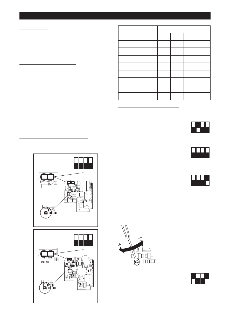
Model SW1
Int.1 Int.2 Int.3 Int.4
LINEO 100 Q V0 ES OFF OFF OFF OFF
LINEO 100 V0 ES OFF OFF OFF ON
LINEO 125 V0 ES OFF OFF ON OFF
LINEO 150 V0 ES OFF OFF ON ON
LINEO 160 V0 ES OFF ON OFF OFF
LINEO 200 V0 ES OFF ON OFF ON
LINEO 250 V0 ES OFF ON ON OFF
LINEO 315 V0 ES OFF ON ON ON
8
Selecting the operating mode
Two-speed mode:
cut off the power supply
set the dip-switch SW2 indicated in
the figure:
Int.2=ON; Int.3=OFF
Int.4=OFF
Adjustable speed mode:
cut off the power supply
set the dip-switch SW2 indicated in
the figure:
Int.2=OFF; Int.3=OFF
Int.4=OFF
Setting the V1 and V2 values
The appliance leaves the factory with default nominal
settings V1=V
Values V1 and V2 can be adjusted as follows:
MIN
, V2=V
MAX
- cut off the power supply
- set the dip-switch SW2 indicated
in the figure:
Int.1=OFF
Int.4=ON
- restore the power supply. The motor automatically
runs at the V1temp speed
- use the trimmer (see
figure) to set V1temp to the
desired value, between
V1nom and the saved V2 –
100Rpm
- set Int.1=ON. This produces two
effects:
the V1temp value is saved as a
new V1;
the motor automatically runs at V2temp;
- use the trimmer (see figure) to set V2temp to the
desired value, between the saved V1 + 100Rpm and
Vmax;
- set Int.1=OFF. This produces two
effects: the V2temp value is saved
as a new V2;
the motor automatically runs at
V1temp
- cut off the power supply
- set Int.4=OFF to lock the V1 and
V2 values
Page 9
ENGLISH
ON
1 2 3 4
OFF
ON
1 2 3 4
OFF
Restoring nominal values
If necessary, the nominal factory-set values for V1
and V2 can be restored using the following
procedure:
- cut off the power supply
- set the dip-switch SW2 indicated
in the figure:
Int.3=ON
- restore the power supply:
V1 and V2 are automatically restored to the nominal
factory-set values corresponding to the selected
model, as described above. The restoring of
nominal values is indicated by two quick flashes of
an LED on the card.
The motor is deactivated automatically
- cut off the power supply
- reset the dip-switch SW2
indicated in the figure:
Int.3=OFF
Operation
Depending on the mode selected during installation:
- two-speed mode: the appliance operates
continuously; two speeds V1 and V2 can be
selected using an external switch
- adjustable speed mode: the appliance can operate
at a speed which is adjusted between 300 Rpm and
Vmax (via an external potentiometer). The Vortice
ON/OFF control box + potentiometer (code 12826,
on request) can also be used.
Maintenance / Cleaning
Fig. 27, 28, 29.
9
Page 10
FRANCAIS
Attention:
ce symbole indique la nécessité de prendre
quelques précautions pour la sécurité
de l’utilisateur
!
Avertissement:
ce symbole indique la nécessité de prendre
quelques précautions pour la sécurité
du produit
!
Description et mode d’employ
L'appareil que vous venez d'acheter est un aérateur
hélico-centrifuge de conduit servant à rejeter l'air
dans un conduit de ventilation.
L'appareil en résine thermoplastique auto-extinguible
V0 est protégé contre les projections d'eau. Il est
équipé d'un moteur brushless à deux vitesses à
commande électronique avec possibilité de réglage
des valeurs de petite et grande vitesse.
Sécurité
• Ne pas utiliser l'appareil pour un usage autre que
celui décrit dans ce livret
• Contrôler l'intégrité de l'appareil après l'avoir sorti
de son emballage : dans le doute, s'adresser
immédiatement à une personne
professionnellement qualifiée ou à un Service
après-vente agréé Vortice. Placer les éléments de
l'emballage hors de la portée des enfants ou des
personnes inexpertes.
• L'utilisation de tout appareil électrique implique le
respect de quelques règles fondamentales dont,
entre autres :
- ne pas toucher l'appareil avec des mains
mouillées ou humides;
- ne pas toucher l'appareil pieds nus;
- interdire son utilisation aux enfants ou aux
personnes inexpertes.
• Cet appareil n'est pas approprié à l'emploi de la
part de personnes (y compris les enfants) avec des
capacités physiques, sensorielles ou mentales
réduites ou sans expérience ni connaissance, à
moins qu'elles ne soient surveillées ou qu'elles
n'aient été instruites au sujet de l'emploi de
l'appareil par une personne responsable de leur
sécurité. Les enfants doivent être surveillés pour
s'assurer qu'ils ne jouent pas avec l'appareil.
• Ranger l'appareil hors de portée des enfants et des
personnes inexpertes après l'avoir débranché du
réseau électrique pour ne plus l'utiliser.
• Ne pas utiliser l'appareil en présence de substances
ou de vapeurs inflammables telles que alcool,
insecticides, essence, explosifs etc.
• En cas de dysfonctionnement et/ou de panne,
s'adresser immédiatement à un Service aprèsvente agréé Vortice et exiger, en cas de réparation,
l'emploi de pièces détachées originales Vortice.
• Si l'appareil tombe ou reçoit des coups violents, le
faire vérifier immédiatement auprès d'un Service
après-vente agréé Vortice
• L'installation électrique à laquelle l'appareil est
branché doit être conforme aux normes en vigueur.
• Brancher l'appareil au réseau d'alimentation/à la
prise électrique si la puissance de l'installation/de la
prise est adaptée à la puissance maximale de
l'appareil. Dans le cas contraire, s'adresser
immédiatement à des professionnels qualifiés
• Pour son installation, prévoir un interrupteur
omnipolaire dont la distance d'ouverture des
contacts est supérieure ou égale à 3 mm.
• Couper l'interrupteur général de l'installation dans
les cas suivants : a) dysfonctionnement ; b) pour
procéder à un nettoyage extérieur ; c) lorsque
l'appareil n'est pas utilisé pendant une longue
période.
• Il est indispensable d’assurer une arrivée d’air
adéquate dans la pièce pour garantir le
fonctionnement de l’appareil.Si dans la pièce à
ventiler, un autre appareil à combustion (tel
quechauffe-eau, radiateur à gaz, etc.) est installé et
qu’il n’est pas étanche, il faut s’assurer que le
renouvellement d’air est adéquat pour garantir le
fonctionnement conjoint des appareils.
• L'appareil ne peut être utilisé comme activateur de
chauffe-eau, poêle etc. et il ne doit pas expulser
dans les conduits d'air chaud de ces appareils.
• L'appareil doit expulser l'air dans un conduit lui
étant exclusivement réservé.
• Ne pas couvrir ni obstruer les deux grilles
d'aspiration et de refoulement de l'appareil pour
assurer le passage optimal de l'air.
• La bouche d’extraction et de refoulement de
l’appareil doit toujours être raccordée à un conduit.
• La température ambiante maximum pour le
fonctionnement de l'appareil est de 50° C.
• La protection contre les températures excessives et
les surcharges est assurée par un fusible et par
l’électronique de commande.
• Les données électriques du réseau doivent
correspondre à celles inscrites sur la plaque A.
(Fig.A)
Les informations requises par le Règlement
327/2011 UE se trouvent sur la plaquette B. (mod.
315 ES, Fig.A)
• Ne modifier l'appareil en aucune façon.
• Ne pas exposer l'appareil aux agents
atmosphériques (pluie, soleil etc).
• Ne rien poser sur l’appareil.
• Contrôler périodiquement, de visu, l'intégrité de
l'appareil. En cas de défectuosité, ne pas utiliser
l'appareil et contacter immédiatement un Service
après-vente agréé Vortice.
10
Applications typiques
Figg. 1-2;
Lorsque l'appareil est installé à une hauteur inférieure
à 2,3 m du sol et la longueur des tuyaux reliés en
extraction et refoulement le requiert, il est opportun
de monter des dispositifs visant à prévenir le risque
de contacts avec l'hélice.
Page 11
FRANCAIS
ON
1 2 3 4
OFF
DIPSWITCH
TRIMMER
12
SW 1 : MODEL
SW 2 : SETUP
ON
1 2 3 4
OFF
DIPSWITCH
12
SW 1 : MODEL
SW 2 : SETUP
TRIMMER
ON
1 2 3 4
OFF
ON
1 2 3 4
OFF
ON
1 2 3 4
OFF
Installation
Fig. 3 ÷ 26;
Fig.3: E= Plaquette de direction du débit d’air; C=
Aspiration; D= Refoulement;
Configuration initiale
L'installateur doit configurer l'appareil en suivant les
étapes décrites ci-après.
sélection du modèle d'appareil
phase est réalisée en usine. Les instructions
présentes dans la notice peuvent être utiles
uniquement s'il s'avère nécessaire de rétablir la
situation au cas où le dip-switch aurait été
endommagé.
sélection du mode de fonctionnement
Deux modes sont prévus : à deux vitesses V1 et V2,
à sélectionner à travers l'interrupteur extérieur, ou à
vitesse réglable via potentiomètre extérieur.
programmation des valeurs V1 et V2
fonctionnement à deux vitesses)
Sélection du modèle d'appareil
Sélectionner le modèle en configurant le dip-switch
indiqué sur la figure et en suivant les descriptions
dans le tableau suivant.
LINEO 100 Q V0 ES - LINEO 200 V0 ES
: voir ci-après. Cette
: voir ci-après.
(pour le mode de
Model SW1
Int.1 Int.2 Int.3 Int.4
LINEO 100 Q V0 ES OFF OFF OFF OFF
LINEO 100 V0 ES OFF OFF OFF ON
LINEO 125 V0 ES OFF OFF ON OFF
LINEO 150 V0 ES OFF OFF ON ON
LINEO 160 V0 ES OFF ON OFF OFF
LINEO 200 V0 ES OFF ON OFF ON
LINEO 250 V0 ES OFF ON ON OFF
LINEO 315 V0 ES OFF ON ON ON
Sélection du mode de fonctionnement
Mode à deux vitesses :
mettre l'appareil hors tension
configurer, sur le dip-switch SW2 indiqué sur la figure :
Int.2=ON; Int.3=OFF
Int.4=OFF
Mode à vitesse réglable :
mettre l'appareil hors tension
configurer, sur le dip-switch SW2
indiqué sur la figure :
Int.2=OFF; Int.3=OFF
Int.4=OFF
Programmation des valeurs V1 et V2
L'appareil quitte l'usine avec des valeurs nominales
par défaut V1=V
Il est possible de régler les valeurs V1 et V2 en
procédant de la façon suivante :
- mettre l'appareil hors tension
- configurer, sur le dip-switch SW2
indiqué sur la figure:
Int.1=OFF
Int.4=ON
- remettre l'appareil sous tension. Le moteur tourne
automatiquement à la vitesse V1temp
, V2=V
MIN
MAX
-- tourner le trimmer (voir
figure) pour régler V1temp
sur une valeur au choix,
comprise entre V1nom et la
V2 mémorisée – 100Rpm
LINEO 250 V0 ES, LINEO 315 V0 ES
- programmer Int.1=ON. Ceci produit deux effets:
la valeur V1temp est mémorisée comme nouvelle
11
Page 12
FRANCAIS
ON
1 2 3 4
OFF
ON
1 2 3 4
OFF
ON
1 2 3 4
OFF
ON
1 2 3 4
OFF
ON
1 2 3 4
OFF
valeur V1
le moteur tourne
automatiquement à la vitesse
V2temp
- tourner le trimmer (voir figure) pour régler V2temp
sur une valeur au choix, comprise entre V1
mémorisée + 100 et Vmax
- programmer Int.1=OFF. Ceci
produit deux effets :
la valeur V2temp est mémorisée
comme nouvelle valeur V2
le moteur tourne automatiquement à la vitesse
V1temp
- mettre l'appareil hors tension
- programmer Int.4=OFF pour
bloquer les valeurs V1 et V2
Rétablissement des valeurs
nominales
Si nécessaire, il est possible de rétablir les valeurs
nominales d'usine pour V1 et V2 à travers la
procédure suivante :
- mettre l'appareil hors tension
- configurer, sur le dip-switch SW2
indiqué sur la figure :
Int.3=ON
- remettre l'appareil sous tension:
V1 et V2 sont automatiquement rétablies aux
valeurs nominales par défaut en fonction du modèle
sélectionné, comme décrit ci-dessus. Lorsque les
valeurs nominales sont rétablies, une led
embarquée sur la carte clignote rapidement pour
signaler l'opération.
Le moteur est automatiquement désactivé.
- mettre l'appareil hors tension
- rétablir, sur le dip-switch SW2
indiqué sur la figure:
Int.3=OFF
Fonctionnement
Le fonctionnement dépend du mode choisi en phase
d'installation :
- mode à deux vitesses : l’appareil fonctionne en
mode continu ; possibilité de sélectionner deux
vitesses V1 et V2 à travers l'interrupteur extérieur
- mode à vitesse réglable : l'appareil peut fonctionner
à vitesse réglable, de 300 Rpm à Vmax (via
potentiomètre extérieur). Possibilité d'utiliser
également le boîtier de commandes Vortice
ON/OFF + potentiomètre (réf. 12826, sur demande).
Entretien / nettoyage
Fig. 27, 28, 29.
12
Page 13
DEUTSCH
Achtung:
dieses Symbol zeigt Vorsichtsmaßnahmen an
um Schäden am Bediener zu vermeiden
!
Hinweis:
dieses Symbol zeigt Vorsichtsmaßnahmen an
um Schäden am Gerät zu vermeiden
!
Beschreibung und Gebrauch
Bei dem von Ihnen erworbenen Gerät handelt es sich
um einen Mischströmung-Rohrlüfter zum Absaugen
der Luft über ein Entlüftungsrohr.
Das Gerät ist aus selbstverlöschendem,
thermoplastischem Harz V0 gefertigt,
spritzwassergeschützt, und hat einen elektronisch
gesteuerten, bürstenlosen Motor mit zwei
Geschwindigkeitsstufen und verstellbarer Mindestund Höchstgeschwindigkeit.
Sicherheit
• Dieses Gerät darf nur für den in dieser Anleitung
angegebenen Verwendungszweck eingesetzt
werden.
• Das Gerät nach dem Auspacken auf
Transportschäden oder andere Mängel
untersuchen; im Zweifelsfall unverzüglich einen
Vortice-Vertragshändler verständigen. Das
Verpackungsmaterial nicht in Reichweite von
Kindern oder Personen lassen, die sich damit
schaden könnten.
• Beim Einsatz von Elektrogeräten jeder Art müssen
einige Grundregeln stets beachtet werden, wie
unter anderem:
- Das Gerät nicht mit nassen oder feuchten Händen
berühren;
- Nicht barfuß berühren;
- Nicht unbeaufsichtigt von Kindern oder Personen,
die sich damit schaden könnten, benutzen
lassen.
• Dieses Gerät darf von Kindern oder Personen mit
eingeschränkten körperlichen oder geistigen
Fähigkeiten oder mangelnder Erfahrung bzw.
Kenntnis nur unter der Aufsicht oder nach
gründlicher Unterweisung und Überprüfung seitens
einer für ihre Sicherheit verantwortlichen Person
bedient werden. Kinder sind zu überwachen, damit
sie nicht mit dem Gerät spielen.
• Wird das Gerät nicht mehr benutzt, muss es vom
Stromnetz getrennt und außerhalb der Reichweite
von Kindern und Personen, die es allein nicht
sachgemäß bedienen können, aufbewahrt werden.
• Das Gerät nicht in der Nähe entflammbarer
Substanzen oder Dämpfe wie Alkohol, Insektizide,
Benzin usw. verwenden.
• Keine Änderungen am Gerät anbringen.
• Das Gerät keinen Witterungseinflüssen (Regen,
Sonneneinstrahlung usw.) aussetzen.
• Keine Gegenstände auf dem Gerät ablegen.
• Regelmäßig den einwandfreien Zustand des
Gerätes überprüfen. Bei festgestellten Mängeln das
Gerät nicht benutzen und sofort einen Vortice-
Vertragshändler verständigen.
• Bei Betriebsstörungen und/oder defektem Gerät
sofort einen Vortice-Vertragshändler aufsuchen und
für eine eventuelle Reparatur die Verwendung von
Vortice-Originalersatzteilen verlangen.
• Fällt das Gerät hin oder wurde es starken Stößen
ausgesetzt, muss es sofort von einem VorticeVertragshändler überprüft werden.
• Die Elektroanlage, an die das Produkt
angeschlossen werden soll, muss den geltenden
Vorschriften entsprechen.
• Das Produkt nur dann an das Stromnetz
anschließen, wenn die Stromfestigkeit der
Anlage/Steckdose für die maximale Leistung
geeignet ist. Sollte dies nicht der Fall sein, sofort
qualifiziertes Fachpersonal beiziehen
• Bei der Installation ist ein allpoliger Schalter mit
einer Kontaktöffnungsweite von mindestens 3 mm
vorzusehen.
• Schalten Sie den Hauptschalter aus, wenn: a) eine
Betriebsstörung festgestellt wird. b) das
Geräteäußere gereinigt werden muss. c) das Gerät
längere Zeit nicht benutzt wird.
• Es muss gewährleistet sein, dass genügend Luft in
den Raum nachströmen kann, damit das Gerät
einwandfrei funktioniert. Wenn im selben Raum eine
mit Brennstoff betriebene Heizvorrichtung (z.B.
Durchlauferhitzer, Methangasofen o.ä.) installiert ist,
die zur Raumluft nicht abgedichtet ist, muss dafür
gesorgt werden, dass die nachströmende Luft auch
für den einwandfreien Verbrennungsablauf dieser
Vorrichtung ausreicht.
• Das Gerät darf nicht als Aktivator für Heizlüfter,
Öfen usw. benutzt werden. Die Abluft darf nicht in
Warmluftleitungen geleitet werden.
• Die Abluft des Gerätes muss in einen separaten
Kanal (der ausschließlich von diesem Gerät genutzt
wird) geleitet werden.
• Die beiden Ansaug- und Auslassgitter des Gerätes
stets freihalten, damit ein optimaler Luftdurchgang
gewährleistet wird.
• Der Zu- und der Abluftstutzen des Gerätes müssen
immer an eine Rohrleitung angeschlossen sein
• Die maximal zulässige Umgebungstemperatur für
den Betrieb des Gerätes beträgt 50°.
• Eine Schmelzsicherung und die Steuerelektronik
schützen das Gerät vor Überhitzung und
Überlastung.
• Die elektrischen Daten der Netzversorgung müssen
den Angaben auf dem Typenschild A entsprechen
(Abb. A).
Das Typenschild B enthält die Daten gemäß
Verordnung (EU) Nr. 327/2011.(mod. 315 ES, Abb.
A).
Typische Anwendungsarten
Abb. 1-2;
Wird das Gerät tiefer als 2,3 m über dem Boden
installiert, und sind die Zu- bzw. Ableitungen relativ
kurz, müssen geeignete Schutzvorrichtungen
montiert werden, die einen direkten Kontakt mit dem
Läufer verhindern
13
Page 14

DEUTSCH
ON
1 2 3 4
OFF
ON
1 2 3 4
OFF
ON
1 2 3 4
OFF
DIPSWITCH
TRIMMER
12
SW 1 : MODEL
SW 2 : SETUP
ON
1 2 3 4
OFF
DIPSWITCH
12
SW 1 : MODEL
SW 2 : SETUP
TRIMMER
ON
1 2 3 4
OFF
ON
1 2 3 4
OFF
ON
1 2 3 4
OFF
Einstellung
Abb. 3 ÷ 26
Abb.3: E = Anzeige der Luftströmungsrichtung;
C=Ansaugung; D= Auslass;
Anfangskonfiguration
Der Installateur muss den Betrieb des Geräts wie
nachstehend beschrieben konfigurieren.
Auswahl des Gerätemodells
Phase wird im Werk durchgeführt, die in dieser
Betriebsanleitung enthaltenen Beschreibungen sind
nur nützlich, wenn die ursprüngliche Situation
wiederhergestellt werden muss, nachdem die DIPSchalter versehentlich verstellt wurden.
Auswahl des Betriebsmodus
zwei Betriebsmodi: mit zwei, über einen externen
Schalter auswählbaren Drehzahlstufen V1 und V2
oder mit über ein externes Potentiometer
verstellbarer Drehzahl.
Einstellung der Werte V1 und V2
Betriebsmodus mit zwei Drehzahlstufen)
Auswahl des Gerätemodells
Die Auswahl des Gerätemodells erfolgt durch
Konfiguration des abgebildeten DIP-Schalters und
wie in der nachstehenden Tabelle beschrieben.
: siehe unten. Diese
: siehe unten. Es gibt
LINEO 100 Q V0 ES - LINEO 200 V0 ES
LINEO 250 V0 ES, LINEO 315 V0 ES
(beim
Model SW1
Int.1 Int.2 Int.3 Int.4
LINEO 100 Q V0 ES OFF OFF OFF OFF
LINEO 100 V0 ES OFF OFF OFF ON
LINEO 125 V0 ES OFF OFF ON OFF
LINEO 150 V0 ES OFF OFF ON ON
LINEO 160 V0 ES OFF ON OFF OFF
LINEO 200 V0 ES OFF ON OFF ON
LINEO 250 V0 ES OFF ON ON OFF
LINEO 315 V0 ES OFF ON ON ON
Auswahl des Betriebsmodus
Betriebsmodus mit zwei Drehzahlstufen:
Die Stromversorgung trennen
Den abgebildeten DIP-Schalter SW2 wie folgt
einstellen:
Int.2=ON; Int.3=OFF
Int.4=OFF
Betriebsmodus mit regelbarer
Drehzahl:
Die Stromversorgung trennen
Den abgebildeten DIP-Schalter SW2
wie folgt einstellen:
Int.2=OFF; Int.3=OFF
Int.4=OFF
Einstellung der Werte V1 und V2
Werkseitig wird das Gerät auf die Defaultwerte
V1=V
Die Werte V1 und V2 können wie folgt eingestellt
werden:
- Die Stromversorgung trennen
- Den abgebildeten DIP-Schalter
- Die Stromversorgung wieder
, V2=V
MIN
SW2 wie folgt einstellen:
Int.1=OFF
Int.4=ON
herstellen. Der Motor wird automatisch auf die
Drehzahl V1temp gebracht
MAX
- Den Trimmer (siehe
Abbildung) verstellen, um
V1temp auf den
gewünschten Wert
zwischen V1nom und dem
gespeicherten V2 - 100Rpm
einzustellen
14
Page 15
ON
1 2 3 4
OFF
ON
1 2 3 4
OFF
ON
1 2 3 4
OFF
DEUTSCH
ON
1 2 3 4
OFF
ON
1 2 3 4
OFF
- Int.1=ON einstellen. Diese
Einstellung hat zweierlei
Auswirkungen:
Der Wert V1temp wird als neuer
Wert V1 gespeichert
Der Motor wird automatisch auf die Drehzahl
V2temp gebracht
- Den Trimmer (siehe Abbildung) verstellen, um
V2temp auf den gewünschten Wert zwischen dem
gespeicherten V1 + 100Rpm und Vmax einzustellen
- Int.1=OFF einstellen. Diese
Einstellung hat zweierlei
Auswirkungen:
Der Wert V2temp wird als neuer
Wert V2 gespeichert
Der Motor wird automatisch auf die Drehzahl
V1temp gebracht
- Die Stromversorgung trennen
- Int.4=OFF einstellen, um die
erte V1 und V2 zu blockieren
Wiederherstellen der
Nennwerte
Falls erforderlich, können die werkseitigen Nennwerte
V1 und V2 wie folgt wieder hergestellt werden:
- de Stromversorgung trennen
- den abgebildeten DIP-Schalter
SW2 wie folgt einstellen:
Int.3=ON
- Die Stromversorgung wieder
herstellen:
- V1 und V2 werden automatisch wieder auf die
werkseitigen Nennwerte des wie oben beschrieben
ausgewählten Modells zurückgesetzt. Die erfolgte
Wiederherstellung der Nennwerte wird von zwei
schnellen Blinkimpulsen einer LED an der Platine
angezeigt. Der Motor wird automatisch deaktiviert
- Die Stromversorgung trennen
- Den abgebildeten DIP-Schalter
SW2 wieder zurücksetzen:
Int.3=OFF
Betrieb
Abhängig von dem während der Installation
gewählten Betriebsmodus:
- Betriebsmodus mit zwei Drehzahlstufen: das Gerät
hat Dauerbetrieb; mit einem externen Schalter
können zwei Drehzahlstufen V1 und V2 gewählt
werden
- Betriebsmodus mit regelbarer Drehzahl: das Gerät
kann mit regelbarer Drehzahl von 300 Rpm bis
Vmax betrieben werden (mit über ein externes
Potentiometer ) Es kann auch der VorticeSchaltkasten ON/OFF + Potentiometer verwendet
werden (Code 12826, auf Anfrage).
Wartung / Reinigung
Abb. 27, 28, 29.
15
Page 16
ESPAÑOL
Atención:
este simbolo indica precauciones quesirven
para evitar daños al usuario
!
Advertencia:
este simbolo indica precauciones que sirven
para evitar daños en el producto
!
Descripción y uso
El aparato que usted ha adquirido es un aspirador
helicoidal centrífugo que expulsa el aire hacia un
conducto de ventilación.
Está realizado en resina termoplástica
autoextinguible V0, es resistente a las salpicaduras
de agua y posee un motor brushless de dos
velocidades con control electrónico, con la
posibilidad de regular los valores de velocidad
mínima y máxima.
Seguridad
• No emplear este producto con fines distintos a los
previstos por este manual
• Una vez extraído el producto de su embalaje,
comprobar su integridad: en caso de duda,
contactar inmediatamente con personal cualificado
o con un revendedor autorizado de Vortice. No
dejar el embalaje al alcance de niños o personas
discapacitadas
• El empleo de todo tipo de aparato eléctrico
comporta el cumplimiento de algunas reglas
fundamentales, entre las que destacamos:
- no tocarlo con las manos mojadas o húmedas;
- no tocarlo con los pies descalzos;
- permitir el uso a niños o a personas
discapacitadas sin vigilancia.
• Este aparato no es adecuado para el uso por parte
de niños o de personas con capacidades físicas,
sensoriales o psíquicas reducidas, o carentes de la
experiencia y los conocimientos necesarios para
utilizarlo, salvo que lo hagan bajo la supervisión o
las instrucciones de una persona responsable de su
seguridad. No permitir que los niños jueguen con el
aparato.
• En el caso de que no se desee volver a utilizar el
aparato, hay que desconectarlo de la red eléctrica y
colocarlo lejos del alcance de niños y personas
discapacitadas.
• No emplear el aparato en presencia de sustancias o
vapores inflamables, como alcohol, insecticidas,
gasolina, etc.
proveedor autorizado de Vortice. En caso de
reparación, exigir que se utilicen recambios
originales Vortice.
• Si el aparato se cae o recibe un golpe fuerte,
contactar inmediatamente con un Centro de
Asistencia Técnica autorizado por Vortice.
• La instalación eléctrica a la que se ha de conectar
el aparato debe ser conforme con las normas
vigentes
• Conectar el aparato a la red de alimentación
eléctrica o a una toma de corriente sólo si la
capacidad de la instalación o la toma es adecuada
a su potencia máxima. Si no se dispone de una red
con estas características, contactar
inmediatamente con personal cualificado.
• En el momento de la instalación hay que prever un
interruptor omnipolar con distancia de apertura
entre los contactos igual o superior a 3 mm.
• Apagar el interruptor general de la instalación: a) en
caso de funcionamiento anómalo; b) antes de
limpiar el aparato por fuera; c) si el aparato no va a
ser utilizado durante algún tiempo.
• Es indispensable asegurar una entrada adecuada
de aire en el local para garantizar el buen
funcionamiento del aparato. Si en el mismo local
hay instalado un aparato no hermético que emplea
combustible (calentador de agua, estufa de gas
metano, etc.), es necesario comprobar que la
entrada de aire garantice también la perfecta
combustión del aparato existente.
• No se puede emplear el aparato como activador de
calentadores de agua, estufas, etc., ni debe
descargar en los conductos de aire caliente de
dichos aparatos.
• El aparato tiene que descargar en un conducto
separado (empleado únicamente por este aparato).
• No tapar ni obstruir las dos rejillas de aspiración y
expulsión del aparato para garantizar la correcta
circulación de aire.
• Las bocas de impulsión y aspiración del aparato
siempre deberán estar conectadas a un conducto.
• La temperatura ambiente máxima de
funcionamiento del aparato es 50° C.
• La electrónica de control y el fusible protegen el
producto contra el sobrecalentamiento y las
sobrecargas.
• Los datos eléctricos de la red deben coincidir con
los de la placa A (Fig.A).
La placa B contiene los datos según el Reglamento
n.327/2011 UE.(mod. 315 ES, Fig.A)
• No aportar al aparato modificaciones de ningún tipo
• No exponer el aparato a los agentes atmosféricos
(lluvia, sol, etc.).
• No apoyar objetos en el aparato.
• Verificar periódicamente la integridad del aparato.
En caso de anomalía, no emplear el aparato y
ponerse en contacto inmediatamente con un
Centro de Asistencia Técnica autorizado por
Vortice.
• Si el aparato no funciona correctamente o se avería,
ponerse en contacto inmediatamente con un
16
Aplicaciones típicas
Cuando el aparato se instala a menos de 2,3 m del
suelo, si la longitud de los tubos conectados en
aspiración e impulsión lo requiere, es oportuno
montar dispositivos para prevenir riesgos de
contacto con el rotor.
Instalación
Fig. 3 ÷ 26;
Page 17
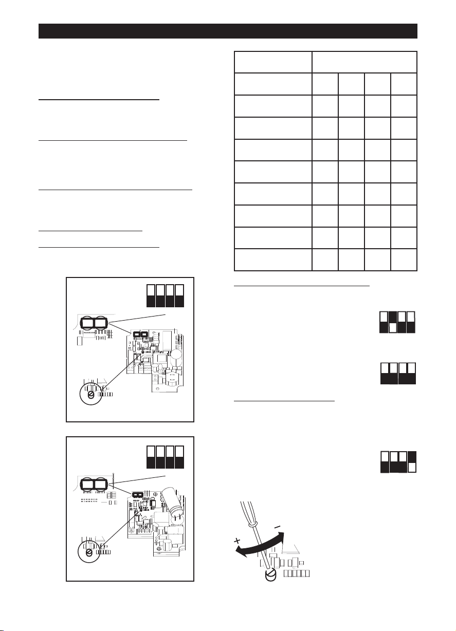
Fig.3: E= Placa de dirección del flujo de aire; C=
ON
1 2 3 4
OFF
DIPSWITCH
TRIMMER
12
SW 1 : MODEL
SW 2 : SETUP
ON
1 2 3 4
OFF
DIPSWITCH
12
SW 1 : MODEL
SW 2 : SETUP
TRIMMER
ON
1 2 3 4
OFF
ON
1 2 3 4
OFF
ON
1 2 3 4
OFF
Aspiración; D= Expulsión;
Configuración inicial
El instalador debe configurar el funcionamiento del
aparato siguiendo los pasos descritos a
continuación.
selección del modelo del producto
continuación. Esta fase se ejecuta en fábrica; las
instrucciones contenidas en este manual pueden ser
útiles sólo en caso de tener que restablecer la
situación después de una alteración accidental de la
posición del microinterruptor.
selección del modo de funcionamiento
continuación. Están previstos dos modos: dos
velocidades, V1 y V2, seleccionables mediante
interruptor externo, o velocidad regulable mediante
potenciómetro externo.
ajuste de los valores V1 y V2
funcionamiento de dos velocidades)
Selección del modelo del producto
La selección del modelo se efectúa con el
microinterruptor 1 indicado en la figura y como se
describe en la tabla siguiente.
ESPAÑOL
LINEO 100 Q V0 ES - LINEO 200 V0 ES
: ver a
: ver a
(en caso de modo de
Model SW1
Int.1 Int.2 Int.3 Int.4
LINEO 100 Q V0 ES OFF OFF OFF OFF
LINEO 100 V0 ES OFF OFF OFF ON
LINEO 125 V0 ES OFF OFF ON OFF
LINEO 150 V0 ES OFF OFF ON ON
LINEO 160 V0 ES OFF ON OFF OFF
LINEO 200 V0 ES OFF ON OFF ON
LINEO 250 V0 ES OFF ON ON OFF
LINEO 315 V0 ES OFF ON ON ON
Selección del modo de funcionamiento
Modo de dos velocidades:
desconectar la alimentación eléctrica
seleccionar con el microinterruptor
SW2 indicado en la figura:
Int.2=ON; Int.3=OFF
Int.4=OFF
Modo de velocidad regulable:
desconectar la alimentación eléctrica
seleccionar con el microinterruptor SW2 indicado en
la figura:
Int.2=OFF; Int.3=OFF
Int.4=OFF
Ajuste de los valores V1 y V2
El aparato sale de fábrica con ajustes nominales
predeterminados V1=V
Es posible regular los valores de V1 y V2 de la
siguiente manera:
- desconectar la alimentación eléctrica
- seleccionar con el
microinterruptor SW2 indicado en
la figura:
Int.1=OFF
Int.4=ON
- conectar la alimentación eléctrica. El motor se pone
automáticamente en la velocidad V1temp
, V2=V
MIN
MAX
- con el trimmer (ver la
figura) regular V1temp en el
valor deseado, entre V1nom
y la V2 memorizada – 100
LINEO 250 V0 ES, LINEO 315 V0 ES
17
Page 18
ESPAÑOL
ON
1 2 3 4
OFF
ON
1 2 3 4
OFF
ON
1 2 3 4
OFF
ON
1 2 3 4
OFF
ON
1 2 3 4
OFF
- seleccionar Int.1=ON. Esto
produce dos efectos:
el valor V1temp se memoriza
como nuevo V1
el motor se pone
automáticamente en la velocidad V2temp.
- con el trimmer (ver la figura) regular V2temp en el
valor deseado, entre la V1 memorizada + 100Rpm y
Vmax
- seleccionar Int.1=OFF. Esto
produce dos efectos:
el valor V2temp se memoriza
como nuevo V2;
el motor se pone automáticamente en la velocidad
V1temp
- desconectar la alimentación
eléctrica
- seleccionar Int.4=OFF para
bloquear los valores de V1 y V2
Restablecimiento de los
valores nominales
Si fuera necesario, es posible restablecer los valores
nominales de fábrica de V1 y V2 con el siguiente
procedimiento:
- desconectar la alimentación eléctrica
- seleccionar con el
microinterruptor SW2 indicado en
la figura:
Int.3=ON
- conectar la alimentación eléctrica:
V1 y V2 se restablecen automáticamente en los
valores nominales de fábrica relativos al modelo
seleccionado, como se describió anteriormente. El
restablecimiento efectivo de los valores nominales
es señalizado por dos parpadeos rápidos de un
LED que se encuentra en la tarjeta.
El motor se desactiva automáticamente.
- desconectar la alimentación eléctrica
- seleccionar con el
microinterruptor SW2 indicado en
la figura:
Int.3=OFF
Funcionamiento
Según el modo de funcionamiento elegido durante la
instalación:
- modo de dos velocidades: el aparato tiene
funcionamiento continuo; es posible seleccionar
dos velocidades V1 y V2 con el interruptor externo
- modo de velocidad regulable: el aparato puede
funcionar a velocidad regulable, de 300Rpm a
Vmax (mediante potenciómetro externo). Se puede
utilizar la caja de mandos Vortice ON/OFF +
potenciómetro (cód. 12826, bajo pedido).
18
Mantenimiento / Limpieza
Fig. 27, 28, 29.
Page 19

NEDERLANDS
Let Op:
dit symbool markeert voorzorgsmaatregelen
om schade aan de gebruiker zu voorkomen
!
Waarschuwing:
dit symbool markeert voorzorgsmaatregelen
om schade aan de product zu voorkomen
!
Beschrijving en gebruik
Het door u aangeschafte product is een
schroefvormig centrifugaal afzuigapparaat met
schroefblad voor de afvoer van lucht in een
ventilatiekanaal.
Het apparaat is gemaakt van thermoplastische
zelfdovende hars V0, het is beschermd tegen
waterspatten en is voorzien van een borstelloze
motor met twee snelheden met elektronische
bediening, met de mogelijkheid om de waarden van
de minimum- en maximumsnelheid in te stellen.
Veiligheid
• Gebruik dit product niet voor andere doeleinden
dan de in deze handleiding aangegeven
toepassingen.
• Controleer, na het verpakkingsmateriaal te hebben
verwijderd, of het apparaat onbeschadigd is; wend
u in geval van twijfel onmiddellijk tot een erkende
Vortice Dealer. Houd het verpakkingsmateriaal
buiten het bereik van kinderen of verstandelijk
gehandicapten.
• Bij het gebruik van alle elektrische apparaten
moeten een aantal basisregels in acht genomen
worden, waaronder:
- raak het apparaat niet met natte of vochtige
handen aan;
- raak het apparaat nooit aan als u op blote voeten
loopt;
- laat kinderen of mensen met een verstandelijke
beperking het apparaat niet zonder toezicht
gebruiken.
• Dit apparaat is niet geschikt voor gebruik door
personen (met inbegrip van kinderen) met beperkte
lichamelijke, sensorische of verstandelijke
vermogens, of zonder ervaring en kennis, tenzij zij
onder toezicht staan of instructies hebben
ontvangen van een voor hun veiligheid
verantwoordelijke persoon over het gebruik van dit
apparaat. Kinderen moeten altijd in de gaten
worden gehouden om er zeker van te zijn dat zij niet
met het apparaat gaan spelen.
• Berg het apparaat op buiten bereik van kinderen en
verstandelijk gehandicapten, wanneer u besluit om
het apparaat niet meer te gebruiken, trek de stekker
uit het stopcontact.
• Gebruik het apparaat niet in aanwezigheid van
ontvlambare stoffen of dampen, zoals alcohol,
insecticiden, benzine, enz.
• Breng geen veranderingen, van welke aard ook, aan
het product aan.
• Zorg dat het apparaat niet aan
weersomstandigheden wordt blootgesteld (regen,
zon, enz.).
• Ga niet op het apparaat zitten en leg er geen
voorwerpen op.
• Kijk regelmatig of het apparaat nog intact is. Ingeval
van een defect, het apparaat niet gebruiken en
onmiddellijk contact opnemen met een erkende
Vortice Dealer.
• Neem in geval van een gebrekkige werking en/of
defect in het apparaat meteen contact op met een
erkende Vortice Dealer en vraag altijd om gebruik
van originele Vortice onderdelen in geval van
reparatie.
• Als het apparaat valt of een harde klap krijgt, laat
het dan controleren bij een erkende Vortice dealer.
• De elektrische installatie waar het apparaat op
aangesloten is moet conform de geldende
regelgeving zijn.
• Sluit het apparaat alleen op het elektriciteitsnet/de
contactdoos aan, indien de stroomsterkte van het
elektriciteitsnet/de contactdoos geschikt is voor het
maximumvermogen van het apparaat. Is dat niet
het geval, raadpleeg dan meteen een vakman.
• Bij de installatie dient u gebruik te maken van een
meerpolige schakelaar met een afstand tussen de
contactpunten van minstens 3 mm.
• Schakel de hoofdschakelaar van de installatie uit als u:
a) een storing in de werking vaststelt; b) de buitenkant
van het apparaat schoon wilt maken; c) besluit het
apparaat gedurende langere tijd niet te gebruiken.
• Voor een optimale werking van het product is het
uitermate belangrijk te zorgen voor voldoende
luchttoevoer in de ruimte. In het geval dat er in
dezelfde ruimte een verbrandingsinstallatie (boiler,
gaskachel, enz.) is geïnstalleerd, die niet van het
luchtdichte type is, ervoor zorgen dat het
terugstromen van de lucht ook de perfecte
verbranding van een dergelijk apparaat garandeert.
• Dit apparaat mag niet gebruikt worden als activator
van boilers, kachels, enz. en evenmin mag de afvoer
worden aangesloten op heteluchtleidingen.
• De afvoer van het apparaat dient aangesloten te
worden op een apart afvoerkanaal (uitsluitend
bestemd voor dit apparaat).
• Laat de gaten voor de luchttoevoer en -afvoer van
het apparaat vrij, om een optimale
luchtdoorstroming te kunnen garanderen.
• De luchtaan- en afvoeropeningen van het apparaat
moeten altijd worden aangesloten op een leiding.
• De maximale omgevingstemperatuur voor de
werking van het apparaat is 50°C.
• De beveiliging tegen oververhitting en overbelasting
wordt gegarandeerd door de zekering en door de
bedieningselektronica.
• De elektrische gegevens van het lichtnet moeten
overeenkomen met die van het merkplaatje A (Fig.A)
Op het plaatje B zijn de gegevens vermeld volgens
Reglement n.327/2011 UE. (mod. 315 ES, Fig.A)
Karakteristieke toepassingen
Fig. 1,2;
Wanneer het apparaat op een hoogte van minder dan
2,3 m van de vloer wordt geïnstalleerd en de lengte
van de aangesloten aan- en afvoerleidingen dit
vereist, is het goed om systemen te monteren die
ervoor zorgen dat contact met de rotor wordt
voorkomen.
19
Page 20
ON
1 2 3 4
OFF
ON
1 2 3 4
OFF
ON
1 2 3 4
OFF
ON
1 2 3 4
OFF
NEDERLANDS
ON
1 2 3 4
OFF
DIPSWITCH
TRIMMER
12
SW 1 : MODEL
SW 2 : SETUP
ON
1 2 3 4
OFF
DIPSWITCH
12
SW 1 : MODEL
SW 2 : SETUP
TRIMMER
Installatie
Fig. 3 ÷ 26;
Fig.3: E= Plaatje luchtstroomrichting; C= Afzuiging;
D= Toevoer.
Eerste configuratie
De installateur moet de werking van het apparaat
configureren door de hierna beschreven stappen te
volgen.
selectie van het model van het product: zie verderop.
Deze fase wordt uitgevoerd in de fabriek, de in dit
boekje vermelde aanwijzingen kunnen alleen nuttig
zijn als het noodzakelijk is de situatie te herstellen na
onbedoeld geknoei aan de dip switch.
selectie van de werkingsmodaliteit
zijn twee modi voorzien: op twee snelheden V1 en V2,
die gekozen kunnen worden met de externe
schakelaar, of met instelbare snelheid met de externe
potentiometer.
instelling van de waarden V1 en V2
werkingsmodaliteit op twee snelheden)
Selectie van het model van het product
De selectie van het model wordt uitgevoerd door het
instellen van de in de afbeelding weergegeven dip
switch 1 en zoals beschreven in de volgende tabel.
LINEO 100 Q V0 ES - LINEO 200 V0 ES
: zie verderop. Er
(in het geval van
Model SW1
Int.1 Int.2 Int.3 Int.4
LINEO 100 Q V0 ES OFF OFF OFF OFF
LINEO 100 V0 ES OFF OFF OFF ON
LINEO 125 V0 ES OFF OFF ON OFF
LINEO 150 V0 ES OFF OFF ON ON
LINEO 160 V0 ES OFF ON OFF OFF
LINEO 200 V0 ES OFF ON OFF ON
LINEO 250 V0 ES OFF ON ON OFF
LINEO 315 V0 ES OFF ON ON ON
Selectie van de werkingsmodaliteit
Modus op twee snelheden:
onderbreek de elektrische voeding
stel op de in de afbeelding weergegeven dip switch
SW2 het volgende in:
Schak.2=ON; Schak.3=OFF
Schak.4=OFF
Modus op instelbare snelheid:
onderbreek de elektrische voeding;
stel op de in de afbeelding weergegeven dip switch
SW2 het volgende in:
Schak.2=OFF; Schak.3=OFF
Schak.4=OFF
Instelling van de waarden V1 en V2
Het apparaat verlaat de fabriek met de nominale
defaultwaarden V1=V
V2=V
MAX
Het is mogelijk om de waarden V1
en V2 in te stellen door als volgt te
werk te gaan:
- onderbreek de elektrische voeding
- stel op de in de afbeelding weergegeven dip-switch
2 het volgende in:
Schak.1=OFF
Schak.4=ON
- herstel de elektrische voeding. De motor wordt
automatisch op de snelheid V1temp gebracht
-- draai aan de trimmer (zie
afbeelding) om V1temp op
de gewenste waarde in te
stellen, tussen V1nom en de
in het geheugen opgeslagen
V2 – 100Rpm
MIN
,
LINEO 250 V0 ES, LINEO 315 V0 ES
20
- stel Schak.1=ON in. Dit heeft
twee effecten:
de waarde V1temp wordt in het
geheugen opgeslagen als nieuwe
V1;
de motor wordt automatisch op V2temp gebracht
- draai aan de trimmer (zie afbeelding) om V2temp op
Page 21
NEDERLANDS
ON
1 2 3 4
OFF
ON
1 2 3 4
OFF
ON
1 2 3 4
OFF
ON
1 2 3 4
OFF
de gewenste waarde in te stellen, tussen de in het
geheugen opgeslagen V1nom + 100Rpm en Vmax
- stel Schak.1=OFF in. Dit heeft
twee effecten:
de waarde V2temp wordt in het
geheugen opgeslagen als nieuwe
V2;
de motor wordt automatisch op V1temp gebracht
- onderbreek de elektrische
voeding
- stel Schak.4=OFF in om de
waarden V1 en V2 in te stellen
Nominale waarden resetten
Indien nodig, kunnen de nominale fabriekswaarden
van V1 en V2 gereset worden, met behulp van de
volgende procedure:
- onderbreek de elektrische voeding
- stel op de in de afbeelding
weergegeven dip-switch SW2 het
volgende in:
Schak.3=ON
- herstel de elektrische voeding:
V1 en V2 worden automatisch gereset naar de
nominale fabriekswaarden met betrekking tot het
geselecteerde model, zoals hierboven is
beschreven. Het herstel van de nominale waarden
wordt aangegeven met een led die twee keer snel
knippert op de printplaat.
De motor wordt automatisch uitgeschakeld
- onderbreek de elektrische voeding
- reset op de in de afbeelding
weergegeven dip-switch SW2 het
volgende:
Schak.3=OF
Werking
Afhankelijk van de in de installatiefase gekozen
modus:
- modus op twee snelheden: het apparaat werkt
voortdurend; er kunnen twee snelheden V1 en V2
geselecteerd worden met de externe schakelaar
- modus op instelbare snelheid: het apparaat kan op
instelbare snelheid, van 300 Rpm tot Vmax (met de
externe potentiometer) werken. Ook de Vortice
ON/OFF bedieningskast + potentiometer (cod.
12826, op aanvraag) kan worden gebruikt.
Onderhoud / reiniging
Fig. 27, 28, 29.
21
Page 22

SVENSKA
Var ning:
denna Symbol anger att försiktighet krävs
för att förhindra personskador
!
Observera:
denna Symbol anger att försiktighet krävs
för att förhindra skador på prod ukten
!
Beskrivning och användning
Produkten som du förvärvat är en spiral
centrifugalfläkt avsedd för utblåsning av luft i
ventilationsrör.
Apparaten är tillverkad av självsläckande plast V0,
den är skyddad mot vattenstänk och är utrustad med
brushless motor med två hastigheter med elektronisk
kontroll, med möjlighet att reglera lägsta och högsta
hastighetsvärden.
Säkerhet
• Använd aldrig apparaten för annat bruk än det som
anges i detta häfte.
• Ta ur apparaten ur emballaget och kontrollera att
den är i fullgott skick. Vid tveksamhet; kontakta
genast en behörig fackman eller en serviceverkstad
som auktoriserats av Vortice. Lämna aldrig delar av
emballaget inom räckhåll för barn eller annan
oförmögen person.
• Vid användning av elektriska apparater måste vissa
grundläggande regler följas, bland annat:
- vidrör inte apparaten med våta eller fuktiga
händer;
- vidrör inte apparaten om du är barfota;
- låt inte barn eller annan oförmögen person
använda apparaten utan övervakning.
• Denna apparat får inte användas av personer
(inklusive barn) med nedsatta fysiska,sensoriska
eller mentala förmågor, eller av personer utan
erfarenhet och kunskap,om inte de är övervakade
eller instruerade om användningen av apparaten av
personer ansvariga för deras säkerhet. Barn ska
övervakas för att garantera att de inte leker med
apparten.
• Placera apparaten på en plats som är oåtkomlig för
barn och oförmögen person, då du har beslutat dig
för att skilja den från elnätet och inte använda den
längre.
• Använd inte apparaten i närvaro av brandfarliga
ämnen eller ångor som t.ex. sprit, insektsmedel,
bensin etc.
funktion, skall apparaten stängas av och lämnas till
en av Vortice utsedd auktoriserad serviceverkstad.
Kräv att Vortice originaldelar används vid
reparationen
• Om apparaten ramlar i golvet eller tar emot hårda
stötar ska den genast kontrolleras av en
återförsäljare som auktoriserats av Vortice.
• Det elektriska systemet som produkten är ansluten
till skall vara i överensstämmelse med gällande
normer.
• Anslut apparaten till elnätet endast om elnätet är
avpassat för apparatens maximala effekt. Om så
inte är fallet, kontakta omgående en behörig
fackman.
• För installationen behövs in allpolig brytare med ett
öppningsavstånd av kontakterna lika med eller mer
än 3 mm.
• Stäng av strömmen med huvudströmbrytaren i
följande fall: a) en funktionsstörning konstateras; b)
i samband med underhåll, när apparatens utsida
skall rengöras; c) när apparaten inte skall användas
under längre perioder.
• För att apparaten ska fungera på korrekt sätt krävs
en tillfredsställande lufttillförsel i lokalen. Om en
annan apparat (varmvattenberedare, värmeelement
som drivs med metan, etc.) som använder luft för
förbränningen är installerad i samma lokal måste
lufttillförseln garantera att förbränningen även för
denna apparat kan ske på säkert sätt.
• Apparaten får inte användas för att aktivera
varmvattenberedare, värmeelement eller dylikt, och
den får inte heller ha utsläpp i dylika apparaters
varmluftsrör
• Apparaten skall ha utsläpp antingen eller separat rör
som används uteslutande för denna apparat.
• Se till att apparatens luftintag och luftutsläpp inte är
igentäppta eller övertäckta så att ett optimalt
luftflöde garanteras.
• Produktens utblåsningsöppningar måste alltid vara
anslutna till ett rör.
• När apparaten är i funktion får
omgivningstemperaturen högst vara 50° C.
• Skyddet mot överhettning och överbelastning på
apparat är garanterat av säkringen och
styrelektroniken.
• Elnätets elektriska data skall motsvara de data som
återges på apparatens märkskylt A .(Bild.A).
Skylten B visar data enligt EU-regelverket
327/2011/EU.(mod. 315 ES, Bild.A)
• Utför inte någon typ av ändringar på produkten.
• Låt inte apparaten utsättas för skadlig påverkan av
regn, snö, salt, kemiska ämnen eller liknande.
• Placera inga föremål på apparaten.
• Inspektera apparaten regelbundet och kontrollera
att den är i fullgott skick. Om fel av någon typ
upptäcks får apparaten inte användas. Kontakta
genast en återförsäljare som auktoriserats av
Vortice.
• I händelse av fel på apparaten och/eller dålig
22
Typiska tillämpningar
Bild 1-2;
När apparaten installeras på en höjd lägre än 2,3 m
från marken och längden på luftintags- och
utblåsningsrören kräver det, är det lämpligt att
montera lämpliga anordningar för att förhindra
kontakt med fläkthjulet
Installation
Bild. 3 ÷ 26;
Page 23

SVENSKA
ON
1 2 3 4
OFF
DIPSWITCH
TRIMMER
12
SW 1 : MODEL
SW 2 : SETUP
ON
1 2 3 4
OFF
DIPSWITCH
12
SW 1 : MODEL
SW 2 : SETUP
TRIMMER
ON
1 2 3 4
OFF
ON
1 2 3 4
OFF
ON
1 2 3 4
OFF
Bild.3: E= Märkplåt för luftflödesriktningen; C= Insug;
D= Utlopp.
Model SW1
Startkonfigurering
Installatören skall konfigurera apparatens funktioner i
de steg som beskrivs nedan.
Val av produktmodell
fabriken, instruktionerna i handboken kan dock vara
till hjälp om det skulle bli nödvändigt att återställa
situationen efter eventuell skada på data på dipomkopplaren.
Val av funktionsläge
med två hastigheter, V1 och V2, som väljs med den
externa kontakten, eller med reglerbar hastighet med
hjälp av den externa potentiometern.
Inställning av värdena V1 och V2
funktion i två hastigheter)
Val av produktmodell
Val av modell utförs genom en inställning av dipomkopplaren 1, se bild, på det vis som beskrivs i
tabellen nedan
: se nedan. Denna fas utförs på
: se nedan. Det finns två lägen:
: (vid läget med
Int.1 Int.2 Int.3 Int.4
LINEO 100 Q V0 ES OFF OFF OFF OFF
LINEO 100 V0 ES OFF OFF OFF ON
LINEO 125 V0 ES OFF OFF ON OFF
LINEO 150 V0 ES OFF OFF ON ON
LINEO 160 V0 ES OFF ON OFF OFF
LINEO 200 V0 ES OFF ON OFF ON
LINEO 250 V0 ES OFF ON ON OFF
LINEO 315 V0 ES OFF ON ON ON
Val av funktionsläge
Läge med två hastigheter:
Skilj apparaten från elnätet
Ställ in följande på dip-omkopplaren SW2 som visas i
bilden:
Int.2=ON (på); Int.3=OFF
Int.4=OFF (av)
Läge med reglerbar hastighet:
Skilj apparaten från elnätet
Ställ in följande på dip-omkopplaren SW2 som visas i
bilden:
Int.2=OFF (av); Int.3=OFF
Int.4=OFF (av)
LINEO 100 Q V0 ES - LINEO 200 V0 ES
LINEO 250 V0 ES, LINEO 315 V0 ES
Inställning av värdena för V1 och V2
Apparaten lämnar fabriken med nominella
fabriksinställningarna V1=V
Det går att reglera värdena V1 och V2 genom att göra
MIN
, V2=V
MAX
så som följer:
- Skilj apparaten från elnätet
- Ställ in följande på dip-omkopplaren SW2 som
visas i bilden:
Int.1=OFF (av)
Int.4=ON (på)
- Återanslut apparaten till elnätet.
Motorn går automatiskt till
hastigheten V1temp
- Ställ med hjälp av
trimmern (se bild) in V1temp
till det värde du önskar,
mellan V1nom och den i
minnet sparade V2 –
100Rpm
23
Page 24

SVENSKA
ON
1 2 3 4
OFF
ON
1 2 3 4
OFF
ON
1 2 3 4
OFF
ON
1 2 3 4
OFF
ON
1 2 3 4
OFF
- Ställ in Int.1=ON (på). Det ger två
effekter:
Värdet V1temp sparas i minnet
som ett nytt V1-värde
Motorn går automatiskt till V2temp
- Ställ med hjälp av trimmern (se bild) in V2temp till
det värde du önskar, mellan det minnet sparade V1
+ 100Rpm och Vmax
- ställ in Int.1=OFF (av). Det ger två
effekter:
värdet V2temp sparas i minnet
som ett nytt V2-värde;
motorn går automatiskt till V1temp
- Skilj apparaten från elnätet
- Ställ in Int.4=OFF (av) för att
blockera värdena för V1 och V2
Återställning av nominella
värden
Om detta skulle vara nödvändigt kan de nominella
värdena återställas till fabriksinställningarna för V1
och V2, genom att göra följande:
- Skilj apparaten från elnätet
- Ställ in följande på dipomkopplaren SW2 som visas i
bilden:
Int.3=ON (på)
-- Återanslut apparaten till elnätet:
V1 och V2 återställs automatiskt till nominella
fabriksvärden, beroende på den modell som valts
enligt beskrivningen ovan. Återställningen av de
nominella värdena signaleras med hjälp av två
snabba blinkningar på lysdioden som sitter på
kortet. Motorn stängs automatiskt av
- Skilj apparaten från elnätet
- Återställ följande på dipomkopplaren SW2 som visas i
bilden:
Int.3=OFF (av)
Funktion
Beroende på det läge som valts under installeringen:
- Läge med två hastigheter: apparaten fungerar
kontinuerligt - det går att välja två hastigheter V1
och V2 med hjälp av den yttre kontakten
- Läge med reglerbar hastighet: apparaten kan
fungera med reglerbar hastighet, från 300 Rpm till
Vmax (med den externa potentiometern). Du kan
även använda Vortice styrbox ON/OFF +
potentiometer (kod. 12826, på begäran).
24
Underhåll/rengöring
Bild. 27, 28, 29.
Page 25

SUOMI
!
Huomio:
tämä merkki var oittaa
henkilövahinkojen vaarasta
Varoitus:
tämä merkki varoittaa laitteelle
aiheutuvien vahinkojen vaarasta
!
Laitteen kuvaus ja käyttö
Hankkimasi laite on keskipakopuhallin, joka imee ilman
ilmastointikanavaan.
Laite on valmistettu itsestään sammuvasta
kestomuovista V0 ja suojattu vesiroiskeilta.
Laitteeseen kuuluu kaksinopeuksinen, elektronisesti
ohjattu harjaton moottori, jonka minimi-ja
maksiminopeus ovat säädettävissä.
Turvallisuus
• Älä käytä laitetta muuhun kuin käyttöohjekirjassa
mainittuun käyttötarkoitukseen
• Purettuasi laitteen pakkauksestaan tarkista, että se ei
ole vaurioitunut kuljetuksen aikana. Jos et ole varma
asiasta, ota yhteys Vorticen huoltoon. Älä jätä
pakkausmateriaaleja lasten tai taitamattomien
henkilöiden ulottuville.
• Kaikkien sähkölaitteiden käyttö edellyttää tiettyjen
perusmääräysten noudattamista. Näitä ovat mm.
Seuraavat:
- älä koske laitteeseen märillä tai kosteilla käsillä;
- älä koske laitteeseen ollessasi paljain jaloin;
- älä anna lasten tai taitamattomien henkilöiden
käyttää laitetta ilman valvontaa
• Tätä laitetta ei ole tarkoitettu fyysisesti, sensorisesti
tai psyykkisesti rajoittuneiden henkilöiden (eikä
myöskään lasten) tai kokemattomien tai
taitamattomien henkilöiden käyttöön, ellei heidän
turvallisuudestaan vastaava henkilö valvo ja opasta
heitä laitteen käytössä. Valvo lapsia ja varmista,
etteivät he käytä laitetta leikeissään.
• Vie laite pois lasten tai taitamattomien henkilöiden
ulottuvilta irrotettuasi sen sähköverkosta käytön
lopettamisen jälkeen.
• Älä käytä laitetta tulenarkojen aineiden tai höyryjen
läheisyydessä (esim. alkoholi, hyönteismyrkyt,
bensiini jne.).
ammattitaitoinen henkilöstö.
• Laitteen saa kytkeä vain määräysten mukaiseen
sähköjärjestelmään.
• Kytke laite verkkovirtaan/pistorasiaan vain, jos
sähköjärjestelmän/pistorasian teho vastaa laitteen
maksimitehoa. Muussa tapauksessa käänny heti
ammattitaitoisen sähköasentajan puoleen.
• Laitteen asennuksessa tarvitaan moninapainen
kytkin, jonka kontaktien väli on vähintään 3 mm.
• Katkaise virta päävirtakytkimestä seuraavissa
tilanteissa: a) havaitset toimintahäiriön, b) huollat tai
puhdistat laitetta ulkopuolelta, c) et aio käyttää
laitetta pitkään aikaan.
• Laitteen asianmukaisen toiminnan varmistamiseksi
huoneeseen tulee johtaa korvausilmaa. Jos samassa
huoneessa on polttoaineella toimiva laite
(vedenlämmitin, kaasuliesi tms.), joka ei ole
tyypiltään tiivis, varmista, että korvausilma riittää
myös kyseisen laitteen polttoaineen täydelliseen
palamiseen.
• Laitetta ei saa käyttää vedenlämmittimen, uunin tms.
aktivaattorina, eikä sen poistoilmaa saa johtaa
kuuman ilman kanaviin.
• Laitteen poisto on johdettava yhteen kanavaan (jota
käytetään ainoastaan tälle laitteelle).
• Älä peitä tai tuki laitteen kahta imu- ja
poistosäleikköä varmistaaksesi optimaalisen
ilmanvaihdon.
• Laitteen syöttö- ja imusuulakkeet on aina liitettävä
kanavaan.
• Laitteen toiminnan aikainen ympäristön
maksimilämpötila on 50 °C.
• Ylilämpö- ja ylikuormitussuojaus on varmistettu
sulakkeella ja ohjausyksikön elektroniikalla.
• Verkkovirran sähköarvojen tulee vastata laitteen
kilvessä A mainittuja tietoja (Kuva A).
Kilpeen B on merkitty EU-asetuksen nro 327/2011
tiedot. (mod. 315 ES, Kuva A)
Tyypilliset käyttökohteet
Kuva 1-2;
Kun laite asennetaan alle 2,3 metrin korkeudelle
maasta ja mikäli imu- ja syöttökanavaan liitettyjen
putkien pituus edellyttää, suositeltavaa on asentaa
varusteet, joka estävät kosketuksen siipipyörään.
• Älä tee laitteeseen minkäänlaisia muutoksia.
• Älä altista laitetta ilmastotekijöille (sade,
auringonpaiste jne.).
• Älä laita mitään esineitä laitteen päälle.
• Tarkista laitteen kunto säännöllisin väliajoin. Jos laite
ei ole moitteettomassa kunnossa, ota heti yhteys
Vorticen valtuutettuun huoltoliikkeeseen
• Jos laite ei toimi oikein ja/tai siinä on jokin vika,
käänny heti Vorticen valtuutetun jälleenmyyjän
puoleen. Mikäli laitetta joudutaan korjaamaan, vaadi
alkuperäisten varaosien käyttöä
• Jos laite putoaa tai siihen kohdistuu voimakkaita
iskuja, toimita se heti tarkastettavaksi Vorticen
valtuutettuun huoltoliikkeeseen.
• Laitteen asennuksen saa suorittaa vain
Asennus
Kuva. 3 ÷ 26;
Kuva.3: E= Ilmanvirtaussuunnan ilmaiseva kilpi; C=
imu; D= Puhallus.
Startkonfigurering
Asentajan on määritettävä laitteen toiminta
seuraavien ohjeiden mukaisesti.
Tuotteen mallin valinta:
Tämä vaihe suoritetaan tehtaalla. Tässä oppaassa
ohjeet jäljempänä.
25
Page 26

ON
1 2 3 4
OFF
ON
1 2 3 4
OFF
ON
1 2 3 4
OFF
ON
1 2 3 4
OFF
ON
1 2 3 4
OFF
ON
1 2 3 4
OFF
SUOMI
ON
1 2 3 4
OFF
DIPSWITCH
TRIMMER
12
SW 1 : MODEL
SW 2 : SETUP
ON
1 2 3 4
OFF
DIPSWITCH
12
SW 1 : MODEL
SW 2 : SETUP
TRIMMER
esitetyistä ohjeista voi olla hyötyä, mikäli asetukset on
palautettava dip-kytkimen vahinkokäytön vuoksi.
Toimintatilan valinta
Laitteessa on kaksi toimintatilaa: kaksinopeuksinen
: ohjeet jäljempänä.
toiminta nopeuksilla V1 ja V2, jotka valitaan ulkoisella
kytkimellä, sekä säädettävän nopeuden toimintatila,
jossa nopeus säädetään ulkoisella potentiometrillä.
V1- ja V2-arvojen asettaminen
käytetään kaksinopeuksisessa toimintatilassa)
Tuotteen mallin valinta
Malli valitaan säätämällä kuvassa esitettyä dip-
(mikäli laitetta
kytkintä 1 alla olevan taulukon ohjeiden mukaisesti
LINEO 100 Q V0 ES - LINEO 200 V0 ES
Toimintatilan valinta
Kaksinopeuksinen toimintatila:
Katkaise virta laitteesta.
Säädä kuvassa esitettyä dip-kytkintä
SW2:
kytkin 2=ON; kytkin 3=OFF
kytkin 4=OFF
Säädettävän nopeuden toimintatila:
Katkaise virta laitteesta.
Säädä kuvassa esitettyä dip-kytkintä
SW2:
kytkin 2=OFF; kytkin 3=OFF
kytkin 4=OFF
V1- ja V2-arvojen asettaminen
Laite toimitetaan tehtaalta määritettynä
oletusarvoisiin nimellisasetuksiin V1=V
V2=V
MAX
.
MIN
V1- ja V2-arvot voidaan säätää seuraavalla tavalla:
- Katkaise virta laitteesta.
- Säädä kuvassa esitettyä dipkytkintä SW2:
kytkin 1=OFF;
kytkin 4=ON;
- Kytke virta. Moottori säätyy automaattisesti
nopeudelle V1temp.
- Säädä V1temp-arvo
potentiometrillä (katso kuva)
haluttuun arvoon arvojen
V1nom ja tallennetun V2arvon - 100Rpm välille.
,
LINEO 250 V0 ES, LINEO 315 V0 ES
Model SW1
Int.1 Int.2 Int.3 Int.4
LINEO 100 Q V0 ES OFF OFF OFF OFF
LINEO 100 V0 ES OFF OFF OFF ON
LINEO 125 V0 ES OFF OFF ON OFF
LINEO 150 V0 ES OFF OFF ON ON
LINEO 160 V0 ES OFF ON OFF OFF
LINEO 200 V0 ES OFF ON OFF ON
LINEO 250 V0 ES OFF ON ON OFF
LINEO 315 V0 ES OFF ON ON ON
26
- Aseta kytkin tilaan 1=ON. Tällä on
kaksi vaikutusta:
V1temp-arvo tallentuu uudeksi
V1-a rvoksi.
Moottori säätyy automaattisesti
nopeudelle V2temp.
- Säädä V2temp-arvo potentiometrillä (katso kuva)
haluttuun arvoon tallennetun V1-arvon + 100Rpm ja
Vmax-arvon välille.
- Aseta kytkin tilaan 1=OFF. Tällä on
kaksi vaikutusta:
V2temp-arvo tallentuu uudeksi
V2-arvoksi;
Moottori säätyy automaattisesti nopeudelle
V1temp.
- Katkaise virta laitteesta.
- Lukitse V1 ja V2 arvot asettamalla
kytkin tilaan 4=OFF
Page 27

SUOMI
ON
1 2 3 4
OFF
ON
1 2 3 4
OFF
Nimellisarvojen palauttaminen
Tarvittaessa tehtaan V1- ja V2-nimellisarvot voidaan
palauttaa seuraavalla tavalla:
- Katkaise virta laitteesta.
- Säädä kuvassa esitettyä dipkytkintä SW2:
kytkin 3=ON
- Kytke virta:
V1- ja V2-arvot palautuvat automaattisesti tehtaan
nimellisarvoihin valitun mallin mukaisesti kuten
edellä on kuvattu. Nimellisarvojen palauttaminen
ilmaistaan emolevyn kahden LED-valon nopealla
vilkkumisella. Moottori sammuu automaattisesti.
- Katkaise virta laitteesta.
- Suorita palautus kuvassa
esitetyllä dip-kytkimellä:
kytkin 3=OFF
Toiminta
Asennuksessa valitun toimintatilan mukaisesti:
- Kaksinopeuksinen toimintatila: laite toimii jatkuvasti,
ja nopeudet V1 ja V2 voidaan valita ulkoisella
kytkimellä.
- Säädettävän nopeuden toimintatila: laite toimii
säädettävällä nopeudella välillä 300 Rpm ja Vmax
(potentiometrillä). On mahdollista käyttää myös
Vortice ON/OFF -ohjausyksikköä + potentiometriä
(koodi 12826, pyynnöstä).
Huolto / Puhdistus
Kuva 27, 28, 29.
27
Page 28

ROMÂNĂ
Atenţie:
acest simbol indică măsuri de precauţie
necesare pentru a evita producerea de pagube
utilizatorului
!
Măsuri de precauţie:
acest simbol indică măsuri de precauţie
necesare pentru a evita defectarea produsului
!
Descrierea şi utilizarea
Aparatul pe care l-aţi cumpărat este un aspirator
elicoidal-centrifugal de conductă, pentru evacuarea
aerului într-o conductă de aerisire.
Aparatul este construit din răşină termoplastică cu
autostingere V0, este protejat împotriva stropilor de
apă şi este dotat cu motor brushless cu două viteze, cu
control electronic, cu posibilitatea de reglare a valorilor
de viteză minimă şi maximă.
Siguranţa
• Nu utilizaţi acest produs în scopuri diferite de cele
prezentate în acest manual.
• După ce aţi despachetat produsul, verificaţi
integritatea acestuia; dacă aveţi dubii, adresaţi-vă
imediat unui dealer autorizat Vortice. Nu lăsaţi
componentele ambalajului la îndemâna copiilor sau
a persoanelor cu handicap.
• Folosirea oricărui aparat electric presupune
respectarea unor reguli fundamentale, printre care:
- nu îl atingeţi cu mâinile ude sau umede;
- nu îl atingeţi când sunteţi desculţ;
- nu permiteţi copiilor sau persoanelor cu handicap,
nesupravegheate, să-l folosească.
• Acest aparat nu trebuie utilizat de persoane (inclusiv
copii) cu capacităţi fizice, senzoriale sau mentale
reduse şi fără experienţă sau cunoştinţe, dacă nu
sunt supravegheate sau instruite în prealabil în
legătură cu folosirea aparatului, de către o persoană
care răspunde de siguranţa lor. Copiii trebuie
supravegheaţi pentru a vă asigura că nu se joacă cu
aparatul.
• Puneţi aparatul astfel încât să nu fie la îndemâna
copiilor şi a persoanelor cu handicap, în momentul în
care hotărâţi să îl deconectaţi de la reţeaua electrică
şi să nu îl mai folosiţi.
• Nu utilizaţi aparatul în prezenţa substanţelor sau a
vaporilor inflamabi li, ca de exemplu alcool,
insecticide, benzină etc.
• Nu aduceţi niciun fel de modificare aparatului.
• Nu lăsaţi aparatul expus la agenţi atmosferici (ploaie,
soare etc.).
• Nu puneţi obiecte pe aparat.
• Verificaţi periodic integritatea aparatului. În cazul unor
imperfecţiuni, nu utilizaţi aparatul şi contactaţi
imediat un dealer autorizat Vortice.
• În cazul unei funcţionări defectuoase şi/sau a unei
defectări a aparatului, adresaţi-vă imediat unui
dealer autorizat Vortice şi cereţi, pentru eventualele
reparaţii, folosirea pieselor de schimb Vortice
originale.
28
• Dacă aparatul cade sau primeşte lovituri puternice,
rugaţi să fie verificat imediat de un dealer autorizat
Vortice.
• Instalarea aparatului trebuie să fie efectuată de către
personal calificat din punct de vedere profesional.
• Instalaţia electrică la care e conectat aparatul trebuie
să fie conformă cu normele în vigoare.
• Conectaţi aparatul la reţeaua de alimentare/priza
electrică doar dacă puterea instalaţiei/prizei este
adecvată pentru puterea sa maximă. În caz contrar,
adresaţi-vă imediat personalului calificat din punct
de vedere profesional.
• La instalare trebuie să fie prevăzut un întrerupător
omnipolar cu o distanţă de deschidere a contactelor
de cel puţin 3 mm.
• Stingeţi întrerupătorul general al instalaţiei: a) când
observaţi o anomalie în funcţionare; b) când hotărâţi
să efectuaţi o operaţiune de curăţare la exterior; c)
când hotărâţi să nu utilizaţi aparatul pe perioade mai
lungi.
• Este indispensabil să asiguraţi afluxul necesar de
aer în încăpere pentru a garanta funcţionarea
produsului. În cazul în care în aceeaşi încăpere mai
este instalat un aparat care funcţionează cu
combustibil (boiler, sobă cu metan etc.), care nu este
etanş, asiguraţi-vă că afluxul de aer garantează şi
perfecta combustie a acestui aparat.
• Aparatul nu poate fi utilizat pentru a activa boilere,
sobe etc. şi nici nu trebuie să evacueze în
conductele de aer cald.
• Aparatul trebuie să evacueze într-o conductă
separată (utilizată doar de către acest produs).
• Nu acoperiţi şi nu astupaţi gurile de aspiraţie şi de
evacuare ale aparatului, astfel încât să se asigure o
circulaţie optimă a aerului.
• Gurile de evacuare şi de aspiraţie ale aparatului
trebuie să fie întotdeauna conectate la o conductă.
• Temperatura ambiantă maximă pentru funcţionarea
aparatului este de 50 °C.
• Protecţia la supratemperatură şi lasuprasarcină a
aparatului este asigurată de siguranţa fuzibilă şi de
dispozitivele electronice de comandă.
• Parametrii electrici ai reţelei trebuie să corespundă
cu cei de pe plăcuţa A (Fig.A).
Pe plăcua B sunt indicate datele în conformitate cu
Regulamentul nr. 327/2011 UE. (mod. 315 ES, Fig.A)
Aplicaţii tipice
Fig. 1-2;
Când aparatul este instalat la o înălţime mai mică de
2,3 m de podea, iar lungimea conductelor conectate la
aspiraţie şi la evacuare necesită acest lucru, este
necesar să se monteze dispozitive care să împiedice
riscul de contact cu rotorul
Instalarea
Figg 3 ÷ 26.
Fig.3: E= Plăcuţă care indică direcţia fluxului de aer;
C=Aspiraţie; D= Evacuare;
Page 29
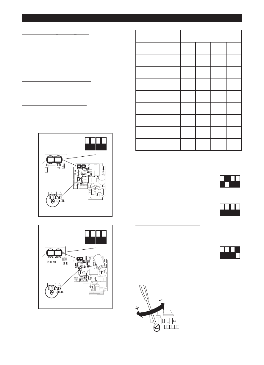
ROMÂNĂ
ON
1 2 3 4
OFF
DIPSWITCH
TRIMMER
12
SW 1 : MODEL
SW 2 : SETUP
ON
1 2 3 4
OFF
DIPSWITCH
12
SW 1 : MODEL
SW 2 : SETUP
TRIMMER
ON
1 2 3 4
OFF
ON
1 2 3 4
OFF
ON
1 2 3 4
OFF
Configuraţia iniţială
Instalatorul trebuie să configureze funcţionarea
aparatului urmând etapele descrise mai jos.
Selectarea modelului produsului:
Această etapă este efectuată în fabrică, instrucţiunile
din această broşură pot fi utile numai în cazul în care
este necesar să se restabilească situaţia în urma unor
manipulări accidentale ale comutatorului „dip
switch”.
Selectarea modului de func
prevăzute două modalităţi: cu două viteze, V1 şi V2,
care pot fi selectate de la întrerupătorul extern, sau cu
viteză reglabilă prin intermediul potenţiometrului
extern.
Setarea valorilor pentru V1
funcţionare cu două viteze).
Selectarea modelului produsului
Selectarea modelului se efectuează cu ajutorul
comutatorului „dip switch” 1 indicat în figură, aşa cum
se descrie în tabelul de mai jos.
ţionare: vezi mai jos. Sunt
şi V2 (în cazul modului de
LINEO 100 Q V0 ES - LINEO 200 V0 ES
LINEO 250 V0 ES, LINEO 315 V0 ES
vezi mai jos.
Model SW1
Int.1 Int.2 Int.3 Int.4
LINEO 100 Q V0 ES OFF OFF OFF OFF
LINEO 100 V0 ES OFF OFF OFF ON
LINEO 125 V0 ES OFF OFF ON OFF
LINEO 150 V0 ES OFF OFF ON ON
LINEO 160 V0 ES OFF ON OFF OFF
LINEO 200 V0 ES OFF ON OFF ON
LINEO 250 V0 ES OFF ON ON OFF
LINEO 315 V0 ES OFF ON ON ON
Selectarea modului de func
Modul cu două viteze:
întrerupeţi alimentarea cu electricitate
setaţi pe comutatorul „dip switch” SW2 indicat în
figură:
Într. 2=ON (Pornit); Într. 3=OFF
Într. 4=OFF (Oprit)
Modul cu viteză reglabilă:
întrerupeţi alimentarea cu electricitate
setaţi pe comutatorul „dip switch” SW2 indicat în
figură:
Într. 2=OFF (Oprit); Într. 3=OFF
Într. 4=OFF (Oprit)
Setarea valorilor pentru V1
Aparatul iese din fabrică având setările nominale
implicite V1=V
Este posibil să se regleze valorile pentru V1 şi V2
MIN
, V2=V
procedând astfel:
- întrerupeţi alimentarea cu
electricitate
- setaţi pe comutatorul „dip switch”
SW2 indicat în figură:
Într.1=OFF (Oprit)
Într. 4=ON (Pornit)
- restabiliţi alimentarea cu electricitate. Motorul
ajunge automat la viteza V1temp
ţionare
şi V2
MAX
-- cu ajutorul condensatorului
de reglare (vezi figura), reglaţi
V1temp pe valoarea dorită,
cuprinsă între V1nom şi V2
memorată – 100Rpm
29
Page 30

ROMÂNĂ
ON
1 2 3 4
OFF
ON
1 2 3 4
OFF
ON
1 2 3 4
OFF
ON
1 2 3 4
OFF
ON
1 2 3 4
OFF
- setaţi Într. 1=ON (Pornit). Acest
lucru are două efecte:
valoarea V1temp este memorată
ca noua valoare pentru V1
motorul ajunge automat la V2temp
- cu ajutorul condensatorului de reglare (vezi figura),
reglaţi V2temp pe valoarea dorită, cuprinsă între V1
memorată + 100Rpm şi Vmax
- setaţi Într. 1=OFF (Oprit). Acest
lucru are două efecte:
valoarea V2temp este memorată
ca noua valoare pentru V2;
motorul ajunge automat la V1temp
- întrerupeţi alimentarea cu
electricitate
- setaţi Într. 4=OFF (Oprit) pentru a
bloca valorile pentru V1 şi V2
Resetarea valorilor nominale
Dacă este necesar, se pot reseta valorile nominale din
fabrică pentru V1 şi V2, prin intermediul următoarei
proceduri:
- întrerupeţi alimentarea cu
electricitate
- setaţi pe comutatorul „dip switch”
SW2 indicat în figură:
Într. 3=ON (Pornit)
- restabiliţi alimentarea cu electricitate:
V1 şi V2 sunt resetate automat la valorile nominale
din fabrică pentru modelul selectat, aşa cum se
arată mai sus. Efectuarea resetării valorilor nominale
este semnalată cu două clipiri rapide ale unui led de
pe cartela electronică. Motorul este dezactivat în
mod automat
- întrerupeţi alimentarea cu
electricitate
- resetaţi pe comutatorul „dip
switch” SW2 indicat în figură:
Într. 3=OFF (Oprit)
Funcţionarea
În funcţie de modul ales în faza de instalare:
- modul cu două viteze: aparatul funcţionează în mod
continuu; se pot selecta două viteze, V1 şi V2, prin
intermediul întrerupătorului extern
- modul cu viteză reglabilă: aparatul poate funcţiona
cu viteză reglabilă, de la 300 la Vmax
(potenţiometrului extern.).
Se poate utiliza şi cutia de comenzi Vortice ON/OFF
+ potenţiometru (cod 12826, la cerere).
30
Întreţinerea / Curăţarea
Fig 27, 28, 29.
Page 31
РУССКИЙ
Oсторожно:
меры
предосторожности, необходимые для
безопасности пользователя
!
Вниманиe:
меры
предосторожности, необходимые для
обеспечения сохранности изделия
!
Описание изделия и способ
его применения
Приобретенное вами изделие представляет собой
центробежный винтовой к анальный вытяжной
вентилятор, предназначенный для удаления
воздуха через вентиляционный воздуховод.
Корпус прибора выполнен из самогасящегося
термопластика V0; прибор защищен от брызг воды
и оснащен двухскоростным бесщеточным
двигателем с электронным управлением с
возможностью задания минимальной либо
максимальной скорости.
Правила техники
безопасности
• Не используйте это изделие для целей, отличных
от предусмотренных настоящей инструкцией.
• После распаковки изделия убедитесь в его
целости и сохранности; в случае сомнений
немедленно обращайтесь к авторизованному
дилеру компании Vortice. Не допускайте
попадания элементов упаковки в руки детей или
лиц с ограниченной дееспособностью.
• Эксплуатация любого электрического устройства
требует соблюдения некоторых основных
правил, в том числе:
- не следует касаться его мокрыми или
влажными руками;
- не следует касаться его, стоя на полу босыми
ногами;
- запрещается его эксплуатация детьми или
недееспособными лицами, находящимися без
присмотра.
• Данное изделие не предназначено для
эксплуатации лицами (включая детей) с
ограниченными физическими, сенсорными или
умственными возможностями или не имеющими
необходимого опыта и знаний за исключением
тех случаев, когда они находятся под
присмотром или получили надлежащие указания
по эксплуатации от лица, ответственного за их
безопасность. Следите за тем, чтобы дети не
играли с аппаратом.
• В случае принятия решения об отключения
устройства от сети и прекращения его
использования поместите его в такое место, где
бы оно не могло попасть в руки детей или
недееспособных лиц.
• Не эксплуатируйте изделие в присутствии
воспламеняемых веществ или паров, таких как
спирт, инсектициды, бензин и т.д.
• Не подвергайте изделие никаким модификациям
или доработкам.
• Не допускайте, чтобы изделие подвергалось
воздействию атмосферных агентов (дождь,
солнце и т.д.).
• Не кладите на изделие какие-либо предметы.
• Периодически проверяйте состояние изделия. В
случае неверной работы не эксплуатируйте
изделие и немедленно обратитесь к
авторизованному дилеру компании Vortice.
• В случае ненормальной работы и/или
неисправности изделия, немедленно обратитесь
к авторизованному дилеру компании Vortice; при
необходимости проведения ремонта запросите
оригинальные запчасти компании Vortice
• В случае падения изделия или получения им
сильных ударов немедленно обратитесь к
авторизованному дилеру компании Vortice для
его проверки.
• Установка изделия должна производится
квалифицированным персоналом
• Система электроснабжения, к которой
подключается изделие, должна соответствовать
действующим нормам.
• Подключайте изделие к сети питания/розетке
только в том случае, если их параметры
соответствуют его максимальной мощности. В
противном случае немедленно обратитесь к
квалифицированному специалисту.
• При монтаже следует предусмотреть установку
рубильника с расстоянием между его
разомкнутыми контактами, равным или большим
3 мм.
• В следующих случаях выключайте рубильник: а)
при проявлении неисправностей в
функционировании изделия; b) при выполнении
внешней чистки изделия; c) в случае принятия
решения о неиспользовании изделия в течение
продолжительного времени.
• Для правильной работы изделия необходимо
обеспечить приток в помещение достаточного
количества воздуха. В случае, когда в таком
помещении установлен прибор негерметичного
типа, работающий за счет сгорания топлива
(водонагревательный котел, печь, работающая
на метане, и т.д.), необходимо удостовериться в
том, что приток воздуха достаточен и для
обеспечения хорошего горения в его камере
сгорания.
• Данное изделие нельзя использовать в качестве
активирующего элемента для
водонагревательных котлов, печей и т.д.;
запрещается также выброс воздуха с него в
воздуховоды горячего воздуха подобных
устройств.
• Всасываемый вентилятором воздух должен
удаляться через отдельный воздуховод
(используемый только для этого изделия) или
непосредственно выводиться наружу.
• Не закрывайте и не загораживайте решетки на
всасывающем и выпускном отверстиях изделия,
чтобы не создавать преграды оптимальному
31
Page 32
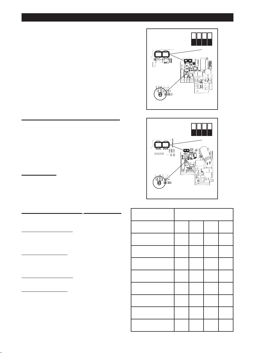
ON
1 2 3 4
OFF
DIPSWITCH
TRIMMER
12
SW 1 : MODEL
SW 2 : SETUP
РУССКИЙ
ON
1 2 3 4
OFF
DIPSWITCH
12
SW 1 : MODEL
SW 2 : SETUP
TRIMMER
прохождению воздуха.
• Нагнетательный и всасывающий патрубки
прибора должны всегда подсоединяться к
воздуховоду
• Максимальная рабочая температура
окружающей среды для данного изделия
составляет 50° C.
• Защита от перегрева и перегрузок
осуществляется на модели с помощью
предохранителя и электронной схемы
управления.
• Параметры электрической сети должны
соответствовать приведенным на табличке А
(рис. А).
На табличке B приведены данные в соответствии с
Регламентом №327/2011 EU (LINEO 315 ES, рис. А).
Обычные виды применения
Рис. 1-2;
Если вентилятор устанавливается на высоте,
меньшей, чем 2,3 метра от пола, и этого требует
длина воздуховодов нагнетания и всасывания,
целесообразно установить устройства,
предотвращающие случайный контакт с
крыльчаткой
Установка
Рис. 3÷26
Рис.3: E = Таблица направления воздушного
потока; C = Всасывание; D = Нагнетание;
LINEO 100 Q V0 ES - LINEO 200 V0 ES
LINEO 250 V0 ES, LINEO 315 V0 ES
Первоначальная настройка
Установщик должен задать режим работы прибора,
следуя приведенным ниже указаниям.
выбор
выполняется на заводе-изготовителе;
приведенные в настоящем руководстве указания
могут быть полезными только в случае случайного
изменения установки внутренних перемычек.
выбор
два режима: с двумя скоростями V1 и V2,
выбираемыми с при помощи внешнего
переключателя; исрегулируемой - при помощи
внешнего потенциометра - скоростью.
задание
с двумя скоростями)
Выбор
Выбор модели производится путем установки
внутренних перемычек, показанных на рисунке, в
соответствии с приведенной ниже таблицей.
32
модели изделия: см. ниже. Этот этап
режима работы: см. ниже. Предусмотрены
значений V1 и V2 (в случае режима работы
модели изделия
Model SW1
Int.1 Int.2 Int.3 Int.4
LINEO 100 Q V0 ES OFF OFF OFF OFF
LINEO 100 V0 ES OFF OFF OFF ON
LINEO 125 V0 ES OFF OFF ON OFF
LINEO 150 V0 ES OFF OFF ON ON
LINEO 160 V0 ES OFF ON OFF OFF
LINEO 200 V0 ES OFF ON OFF ON
LINEO 250 V0 ES OFF ON ON OFF
LINEO 315 V0 ES OFF ON ON ON
Page 33
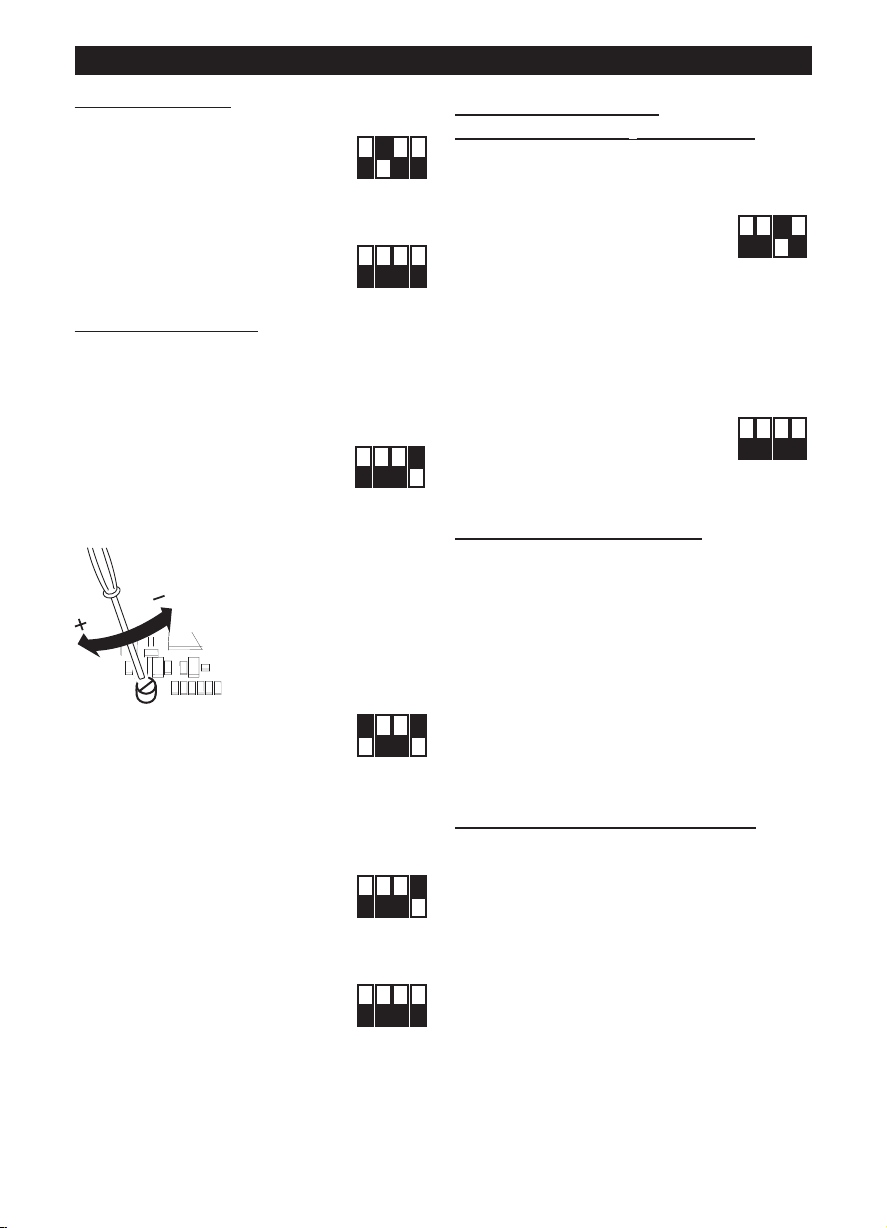
РУССКИЙ
ON
1 2 3 4
OFF
ON
1 2 3 4
OFF
ON
1 2 3 4
OFF
ON
1 2 3 4
OFF
ON
1 2 3 4
OFF
ON
1 2 3 4
OFF
ON
1 2 3 4
OFF
ON
1 2 3 4
OFF
Выбор режима работы
Режим работы с двумя скоростями:
отключите электропитание
установите внутренние перемычки,
показанные на рисунке:
Int.2=ON; Int.3=OFF
Int.4=OFF
Режим работы с регулируемой скоростью:
отключите электропитание
установите внутренние перемычки,
показанные на рисунке:
Int.2=OFF; Int.3=OFF
Int.4=OFF
значений V1 и V2
Задание
Прибор отгружается с завода-изготовителя с
заданными по умолчанию номинальными
значениями V1=V
Значения V1 и V2 можно отрегулировать, действуя
MIN
, V2=V
MAX
следующим образом:
- отключите электропитание
- установите внутренние
перемычки, показанные на
рисунке:
Int.1=OFF
Int.4=ON
- подайте электропитание. При этом двигатель
автоматически установится на скорость V1temp
- с помощью потенциометра
(см. рисунок) отрегулируйте
V1temp на нужное значение
в пределах от V1nom до
сохраненного в памяти
значения V2 – 100Rpm
- задайте Int.1=ON. Это дает
двойной результат:
значение V1temp сохраняется в
качестве нового значения V1;
двигатель автоматически устанавливается на
скорость V2temp
- с помощью потенциометра (см. рисунок)
отрегулируйте V2temp на нужное значение в
пределах от сохраненного в памяти значения V1
+ 100Rpm до Vmax
- задайте Int.1=OFF. Это дает
двойной результат:
значение V2temp сохраняется в
качестве нового значения V2;
двигатель автоматически устанавливается на
скорость V1temp
- отключите электропитание
- задайте Int.4=OFF для фиксации
значений V1 и V2
Восстановление
номинальных значений
В случае необходимости можно восстановить
номинальные заводские значения V1 и V2 с
помощью следующей операции:
- отключите электропитание
- установите внутренние
перемычки, показанные на
рисунке:
Int.3=ON
- подайте электропитание:
V1 и V2 автоматически вернутся к номинальным
заводским значениям, соответствующим модели,
выбранной указанным выше образом. На
восстановление номинальных значений укажут
два быстрых мигания светодиода,
установленного на приборе.
При этом двигатель автоматически выключится
- отключите электропитание
- верните внутренние перемычки,
показанные на рисунке, в
исходное положение:
Int.3=OFF
Функционирование
В зависимости от режима работы, выбранного на
этапе установки:
- режим работы с двумя скоростями: прибор
работает непрерывно; с помощью внешнего
переключателя можно выбрать одну из двух
скоростей V1 и V2
- режим работы с регулируемой скоростью: прибор
может работать со скоростью, регулируемой в
диапазоне от 300 до Vmax (внешнего
потенциометра). Возможно также использование
коробки управления Vortice ВКЛ/ВЫКЛ +
потенциометр (код 12826, поставляется по
отдельному заказу).
Техобслуживание/Чистка
Рис. 27, 28, 29.
33
Page 34
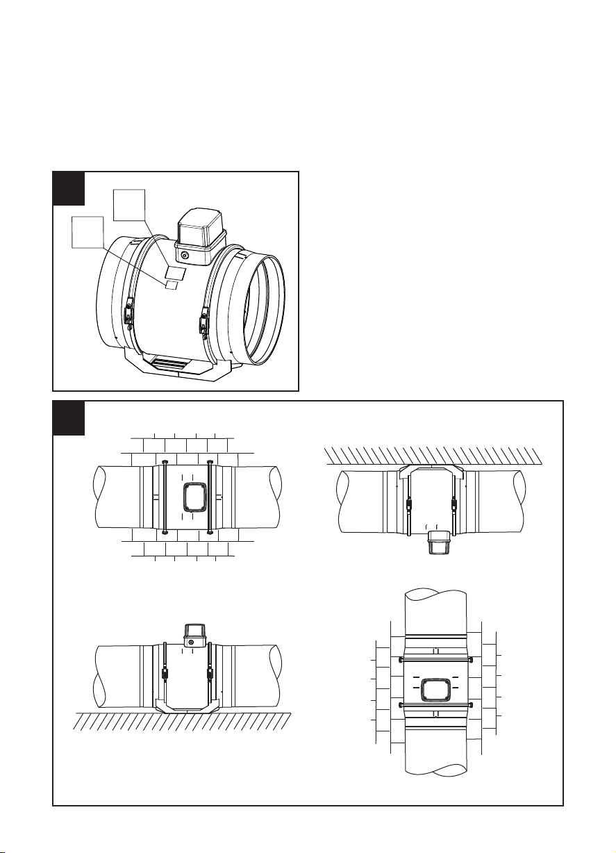
A
B
A
FIGURE
FIGURES
FIGURES
ABBILDUNGEN
FIGURAS
FIGUREN
FIGURER
K U VAT
FIGURILE
ИЛЛЮСТРАЦИИ
1
34
Page 35
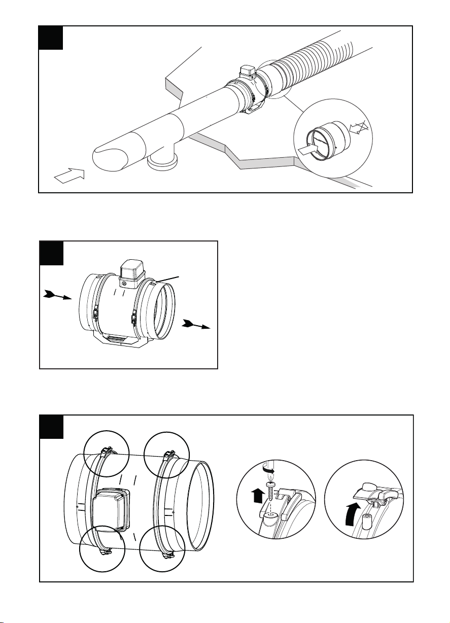
2
2 2
E
3 3
D
C
4 4
35
Page 36

5 5
6 6
7 7
G
Vortice Lineo 100 Q V0 ES
D E Ø F
100-125 -150-160 60 80 6
200 94 100 6
Vortice Lineo V0 ES
315 178 182 8
8 8
9 9
36
Page 37

10 10
11 11
12 12
37
Page 38

16 16
15
LINEO 315 V0 ES
38
Page 39
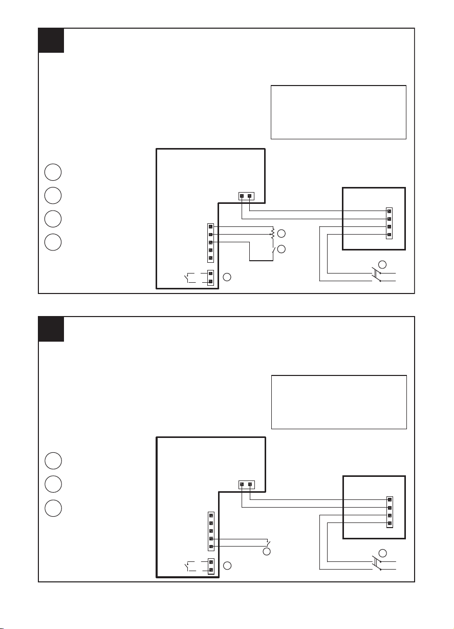
17
1 2 POLES SWITCH (DPST)
1
L
N
2
2
4
4
3
POTENTIOMETER
( FROM 5 KOHM TO 10 KOHM)
3
PCB
COVER
WIRING TO AN EXTERNAL POTENTIOMETER
N L
P0
PI
P10
S1
S2
R2
R1
4
3
L2
N1
ON/OFF SWITCH (SPST)
DRY CONTACT FOR
ALARM SIGNALLING
(250VAC, max current 3A)
NOTES
1) Don’t remove wire connected between contact “N”
of PCB and contact “3” of terminal block on cover
2) Don’t remove wire connected between contact “L”
of PCB and contact “4” of terminal block on cover
LINEO 315 V0 ES
PCB Control Port Description
--------------------------------------P0 = Potentiometer 0V = GND
PI = Potentiometer Input Signal = 0-10V
P10 = Potentiometer 10V = +10V
S1-S2 = dry contact for MAX/MIN speed
R1-R2 = dry contact for optional Alarm
18
1 2 POLES SWITCH (DPST)
1
L
N
2
3
3
LOW/HIGH SPEED SWITCH
SPST
PCB
COVER
WIRING TO AN EXTERNAL LOW/HIGH SPEED SWITCH
N L
P0
PI
P10
S1
S2
R2
R1
4
3
L2
N1
DRY CONTACT FOR
ALARM SIGNALLING
(250VAC, max current 3A)
NOTES
1) Don’t remove wire connected between contact “N”
of PCB and contact “3” of terminal block on cover
2) Don’t remove wire connected between contact “L”
of PCB and contact “4” of terminal block on cover
2
MIN
MAX
LINEO 315 V0 ES
PCB Control Port Description
--------------------------------------P0 = Potentiometer 0V = GND
PI = Potentiometer Input Signal = 0-10V
P10 = Potentiometer 10V = +10V
S1-S2 = dry contact for MAX/MIN speed
R1-R2 = dry contact for optional Alarm
39
Page 40
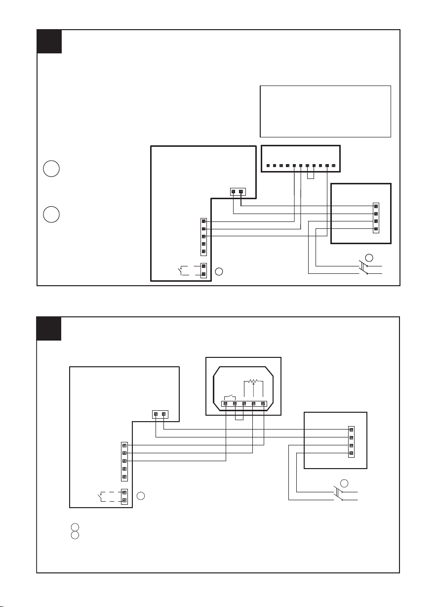
19
1 2 POLES SWITCH (DPST)
1
L
N
2
PCB
COVER
WIRING TO THE “POTENTIOMETER + ON/OFF” CONTROL BOX (CODE 12826)
N L
P0
PI
P10
S1
S2
R2
R1
4
3
L2
N1
DRY CONTACT FOR
ALARM SIGNALLING
(250VAC, max current 3A)
NOTES
1) Don’t remove wire connected between contact “N”
of PCB and contact “3” of terminal block on cover
2) Don’t remove wire connected between contact “L”
of PCB and contact “4” of terminal block on cover
NLN1L1S3S2S1SCBCBNOBNC
CONTROL BOX
LINEO 315 V0 ES
2
PCB Control Port Description
--------------------------------------P0 = Potentiometer 0V = GND
PI = Potentiometer Input Signal = 0-10V
P10 = Potentiometer 10V = +10V
S1-S2 = dry contact for MAX/MIN speed
R1-R2 = dry contact for optional Alarm
20
WIRING TO AN EXTERNAL POTENTIOMETER TYPE DIN
LINEO 315 V0 ES
1 2 POLES SWITCH (DPST)
2
2
1
L
N
DRY CONTACT FOR ALARM SIGNALLING
(250VAC, max current 3A)
PCB/SCHEDA
COVER/COPERCHIO
POTENTIOMETER/POTENZIOMETRO
-(GND)+(OUT)Us
R: 10 Kohm
Switch
10A / 12VDC
4A / 250VAC
4
3
L2
N1
NL
P0
PI
P10
S1
S2
R1
R2
NOTES
1) Don’t remove wire connected between contact “N”
of PCB and contact “3” of terminal block on cover
2) Don’t remove wire connected between contact “L”
of PCB and contact “4” of terminal block on cover
40
Page 41
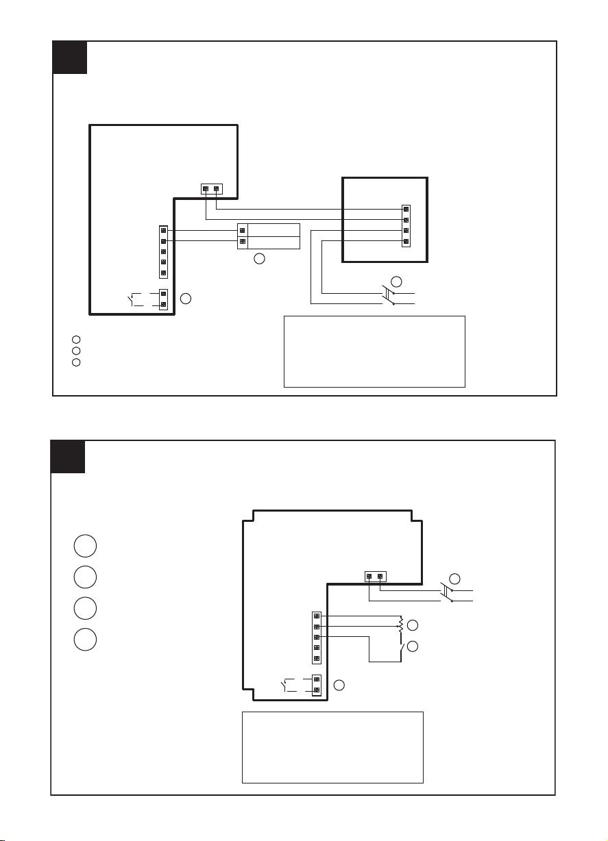
1
2 POLES SWITCH (DPST)
1
L
N
2
3
3
DRY CONTACT FOR ALARM SIGNALLING
(250VAC, max current 3A)
EXTERNAL GENERATOR SIGNAL 0-10V
2
COVER
PCB Control Port Description
--------------------------------------P0 = Potentiometer 0V = GND
PI = Potentiometer Input Signal = 0-10V
P10 = Potentiometer 10V = +10V
S1-S2 = dry contact for MAX/MIN speed
R1-R2 = dry contact for optional Alarm
NOTES
1) Don’t remove wire connected between contact “N”
of PCB and contact “3” of terminal block on cover
2) Don’t remove wire connected between contact “L”
of PCB and contact “4” of terminal block on cover
P0
PI
P10
S1
S2
R2
R1
PCB
GND
OUT (0-10V)
4
3
L2
N1
N
L
21
WIRING TO AN EXTERNAL GENERATOR SIGNAL 0-10V
LINEO 315 V0 ES
22
1 2 POLES SWITCH (DPST)
2
4
3
POTENTIOMETER
( FROM 5 KOHM TO 10 KOHM)
WIRING TO AN EXTERNAL POTENTIOMETER
ON/OFF SWITCH (SPST)
DRY CONTACT FOR
ALARM SIGNALLING
(250VAC, max current 3A)
LINEO V0 ES 100, 125, 150, 160, 100Q, 200, 250
1
L
N
2
3
4
P0
PI
P10
S1
S2
N L
R2
R1
PCB
PCB Control Port Description
--------------------------------------P0 = Potentiometer 0V = GND
PI = Potentiometer Input Signal = 0-10V
P10 = Potentiometer 10V = +10V
S1-S2 = dry contact for MAX/MIN speed
R1-R2 = dry contact for optional Alarm
41
Page 42

24
1 2 POLES SWITCH (DPST)
2
WIRING TO THE “POTENTIOMETER + ON/OFF” CONTROL BOX (CODE 12826)
DRY CONTACT FOR
ALARM SIGNALLING
(250VAC, max current 3A)
LINEO V0 ES 100, 125, 150, 160, 100Q, 200, 250
1
L
N
2
CONTROL BOX
PCB
NLN1L1S3S2S1SCBCBNOBNC
P0
PI
P10
S1
S2
R2
R1
N
L
PCB Control Port Description
--------------------------------------P0 = Potentiometer 0V = GND
PI = Potentiometer Input Signal = 0-10V
P10 = Potentiometer 10V = +10V
S1-S2 = dry contact for MAX/MIN speed
R1-R2 = dry contact for optional Alarm
23
1 2 POLES SWITCH (DPST)
2
3
LOW/HIGH SPEED SWITCH
SPST
WIRING TO AN EXTERNAL LOW/HIGH SPEED SWITCH
DRY CONTACT FOR
ALARM SIGNALLING
(250VAC, max current 3A)
1
L
N
2
3
MIN
MAX
LINEO V0 ES 100, 125, 150, 160, 100Q, 200, 250
P0
PI
P10
S1
S2
PCB
N L
R2
R1
PCB Control Port Description
--------------------------------------P0 = Potentiometer 0V = GND
PI = Potentiometer Input Signal = 0-10V
P10 = Potentiometer 10V = +10V
S1-S2 = dry contact for MAX/MIN speed
R1-R2 = dry contact for optional Alarm
42
Page 43
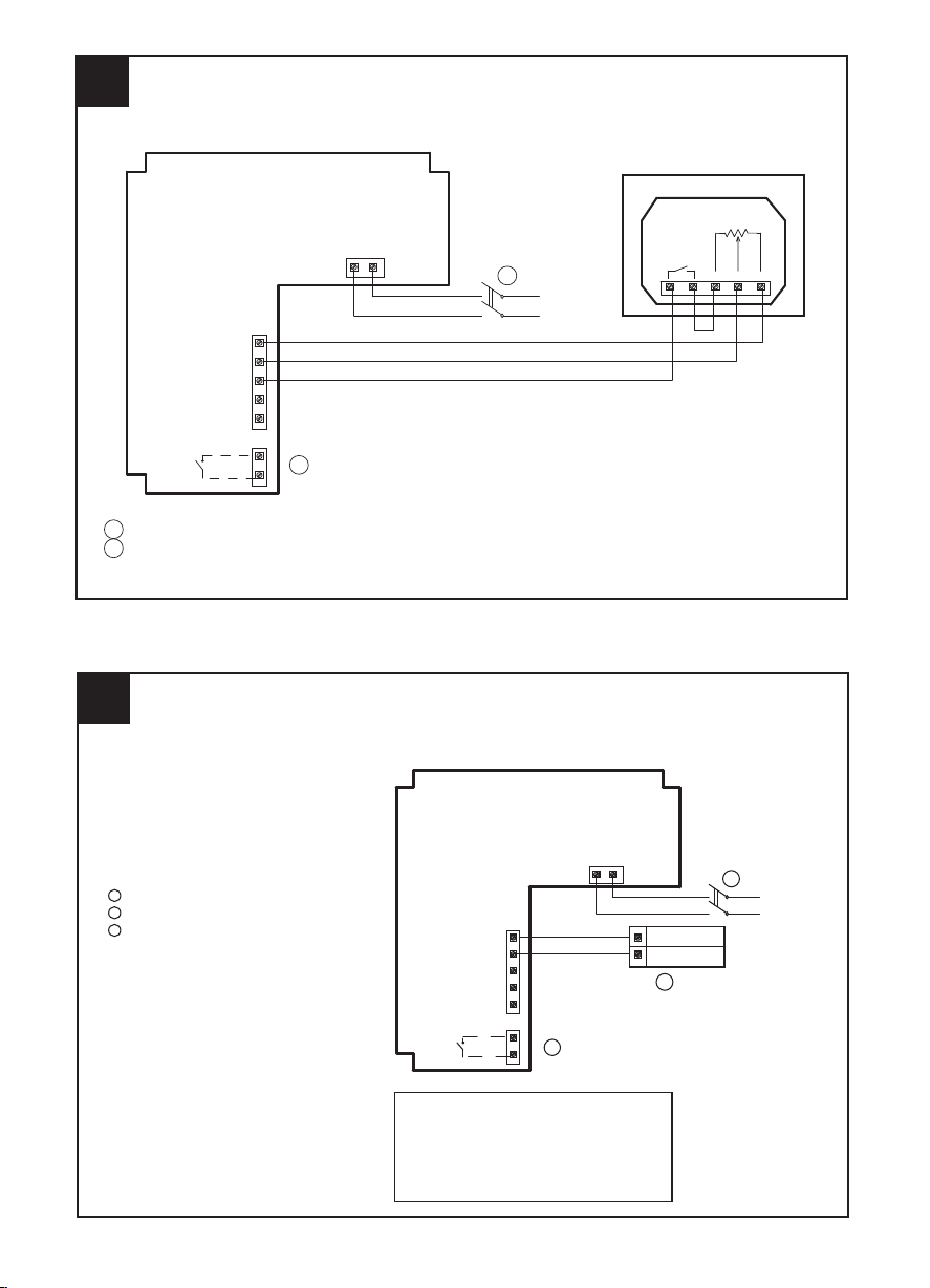
1
2 POLES SWITCH (DPST)
2
3
DRY CONTACT FOR ALARM SIGNALLING
(250VAC, max current 3A)
EXTERNAL GENERATOR SIGNAL 0-10V
PCB Control Port Description
--------------------------------------P0 = Potentiometer 0V = GND
PI = Potentiometer Input Signal = 0-10V
P10 = Potentiometer 10V = +10V
S1-S2 = dry contact for MAX/MIN speed
R1-R2 = dry contact for optional Alarm
26
WIRING TO AN EXTERNAL GENERATOR SIGNAL 0-10V
LINEO V0 ES 100, 125, 150, 160, 100Q, 200, 250
1
L
N
2
PCB
N
L
P0
PI
P10
S1
S2
R2
R1
GND
OUT (0-10V)
3
25
WIRING TO THE EXTERNAL POTENTIOMETER TYPE DIN
1 2 POLES SW IT CH (DPST)
1
L
N
P10
P1
R2
R1
S2
S1
2
2
DRY CONTACT FOR ALARM SIGNALLING
(250VAC, max current 3A)
POTENTIOMETER/POTENZIOMETRO
PCB/SCHEDA
-(GND)+(OUT)Us
R: 10 Kohm
Switch
10A / 12VDC
4A / 250VAC
LN
P0
LINEO V0 ES 100, 125, 150, 160, 100Q, 200,250
43
Page 44

27 27
28 28
29 29
VORTICE LIMITED
Beeches House - Eastern Avenue
Burton on Trent
DE13 0BB
Tel. +44 1283-492949
UNITED KINGDOM
vortice.ltd.uk
sales@vortice.ltd.uk
VORTICE ELETTROSOCIALI S.p.A.
Strada Cerca, 2 - frazione di Zoate
20067 TRIBIANO (MI)
Tel. +39 02-90.69.91
ITALIA
vortice-italy.it
postvendita@vortice-italy.com
VORTICE LATAM S.A.
3er Piso, O
cina 9-B, Edi cio
Meridiano
Guachipelín, Escazú, San José
PO Box 10-1251
Tel +506 2201 6242;
COSTA RICA
vortice-latam.com
info@vortice-latam.com
VORTICE VENTILATION SYSTEM (CHANGZHOU) CO., LTD
Building 19 , No.388 West Huanghe Road, Xinbei District,
Changzhou, Jiangsu Province CAP:213000
CHINA
vortice-china.com
vortice@vortice-china.com
Vortice Elettrosociali S.p.A. si riserva il diritto di apportare tutte le varianti migliorative ai prodotti in corso di vendita.
Vortice Elettrosociali S.p.A. reserves the right to make improvements to products at any time and without prior notice.
La société Vortice Elettrosociali S.p.A. se réserve le droit d'apporter toutes les variations afin d'améliorer ses produits en cours de commercialisation.
Die Firma Vortice Elettrosociali S.p.A. behält sich vor, alle eventuellen Verbesserungsänderungen an den Produkten des Verkaufsangebots vorzunehmen.
Vortice Elettrosociali S.p.A. se reserva el derecho de incorporar todas las mejoras necesarias a los productos en fase de venta.
Vortice Elettrosociali S.p.A.
Page 45

45
Page 46

A
TAGLIANDO INTERVENTO IN GARANZIA
CERTIFICATE OF WORK PERFORMED UNDER GUARANTEE
COUPON INTERVENTION SOUS GARANTIE
DATA INTERVENTO
DATE OF WORK - DATE INTERVENTION
B
TAGLIANDO INTERVENTO IN GARANZIA
STAMP OF TECHNICAL ASSISTANCE CENTRE - CACHET SERVICE APRES-VENTE
TIMBRO CENTRO ASSISTENZA
CERTIFICATE OF WORK PERFORMED UNDER GUARANTEE
COUPON INTERVENTION SOUS GARANTIE
DATA INTERVENTO
DATE OF WORK - DATE INTERVENTION
C
TAGLIANDO INTERVENTO IN GARANZIA
STAMP OF TECHNICAL ASSISTANCE CENTRE - CACHET SERVICE APRES-VENTE
TIMBRO CENTRO ASSISTENZA
CERTIFICATE OF WORK PERFORMED UNDER GUARANTEE
COUPON INTERVENTION SOUS GARANTIE
DATA INTERVENTO
DATE OF WORK - DATE INTERVENTION
STAMP OF TECHNICAL ASSISTANCE CENTRE - CACHET SERVICE APRES-VENTE
TIMBRO CENTRO ASSISTENZA
D
TAGLIANDO INTERVENTO IN GARANZIA
CERTIFICATE OF WORK PERFORMED UNDER GUARANTEE
COUPON INTERVENTION SOUS GARANTIE
DATA INTERVENTO
DATE OF WORK - DATE INTERVENTION
STAMP OF TECHNICAL ASSISTANCE CENTRE - CACHET SERVICE APRES-VENTE
TIMBRO CENTRO ASSISTENZA
Page 47

ITALIA
CONDIZIONI DI GARANZIA
VORTICE SPA garantisce i suoi prodotti per
24 mesi dalla data dell’acquisto che deve
essere comprovata da idoneo documento
scale (scontrino o fattura) rilasciato dal
venditore. Nel suddetto periodo di garanzia
VORTICE SPA si
impegna, dopo aver effettuato le opportune
valutazioni tecniche, a riparare o a
sostituire, gratuitamente, le parti
dell’apparecchio che risultassero affette da
difetti di fabbricazione. La presente
garanzia, da attivare nei modi e nei termini
di seguito indicati, lascia impregiudicati i
diritti derivanti al consumatore dalla
applicazione del D. lgs. 24/2002.Tali diritti,
conformemente alla legge, potranno essere
fatti valere esclusivamente nei confronti del
proprio venditore. La presente garanzia è
valida su tutto il territorio italiano.
Modalità e condizioni di attivazione della
garanzia
Gli interventi in garanzia (riparazioni o
sostituzioni del prodotto ovvero delle parti
difettose) saranno eseguiti presso uno dei
Centri di Assistenza Tecnica autorizzati da
VORTICE il cui indirizzo è disponibile
sull’elenco telefonico alfabetico o
contattando il numero verde 800.555.777.
La prestazione eseguita in garanzia non
prolunga il periodo della garanzia. Pertanto,
incaso di sostituzione del prodotto o di un
suo componente, sul bene o sul singolo
componente fornito in sostituzione non
decorre un nuovo periodo di garanzia ma si
deve tener conto della data di acquisto del
prodotto originario.
UK AND IRELAND
CONDITIONS OF WARRANTY
This guarantee is offered as an extra
benet and does not affect your legal
rights. All electrical appliances produced
by Vortice are guaranteed by the
Company for two years against faulty
material or workmanship.
If any part is found to be defective in this
way within the rst twenty months four
from the date of purchase or hire
purchase agreement, we or our
authorised service agents, will replace or
at our option repair that part without any
charge for materials or labour or
transportation, provided that the
appliance has been used only in
accordance with the instructions
provided with each appliance and has
been not connected to an unsuitable
electricity supply, or subjected to misuse,
neglect or damage or modied or
repaired by any person not authorised by
us.The correct electricity supply voltage
is shown on the rating plate attached to
the appliance.
This guarantee is normally available only
to the original purchaser of the appliance,
but the Company will consider written
applications for transfer.
Should any defect arise in any Vortice
product anda claim under guarantee
become necessary, the appliance should
be carefully packed and returned to your
approved Vortice stockist.This portion of
the guarantee should be attached to the
appliance.
FRANCE
CONDITIONS DE GARANTIE
Votre appareil est couvert par notre garantie à
condition qu’il ne soit pas utilisé à des ns autres
que celles dénies dans nos ches techniques.
Il est garanti pendant deux ans pour l’ensemble
des pièces qui le compose, contre tout vice de
fabrication ou défaut de matiére,
et ce, dès la date de la première mise en service
Cette garantie s’applique au remplacement gratuit
ou à la réparation sans frais des pièces reconnues
défectueuses par nos services; elle ne peut, en
aucun cas, donner lieu à des dommages et
intèréts.
Les frais de transport restant à la charge de
l’utilisateur, et le material voyage à ses risques et
perils.
La garantie sera sans effet si:
• L’appareil a subi un démontage, un
remplacement, de piéce ou une réparation hors
de nos ateliers.
• S’il a été survolté.
• S’il a été utilisé dans une atmosphére
corrosive.
• S’il a été deterioré ou brisé par accident (choc
ou chute....) ou même pendant le transport (le
transporteur est seul responsable).
• La garantie ne s’applique pas sur les pieces à
durée de vie limitée, (ltre charbon, charbon
pour collecteur etc....)
En cas de panne. N’écrivez pas, mais retournez
directement l’appareil soigneusement emballé à
notre service après vente voir coordonnées sur
www.vortice-france.com ou au 01.55.1250.00.
Joindre à l’envoi: le présent certicat de garantie
validé par le vendeur, accompagné d’une note
explicative succinte.
ITALIA
Spedire la garanzia in busta
chiusa a:
Vortice Elettrosociali S.p.A.
Strada Cerca 2
Frazione di Zoate
20067 Tribiano Milano
Autorizzo la Vortice
Elettrosociali S.p.A.
adinserire i miei dati
nelle sue liste e a
comunicarli a terzi
per l’invio di materiale
pubblicitario ed
informativo. In ogni
momento, a norma
dell’art. 13 legge
675/96, potrò avere
accesso ai miei dati,
chiederne la modica
o la cancellazione
oppure oppormi al
loro utilizzo scrivendo
a Vortice
Elettrosociali S.p.A.
Responsabile
trattamento dati Strada Cerca, 2 Frazione di Zoate 20067 Tribiano (MI).
Non autorizzo
(barrare se interessa).
UK-IRELAND
Send the guarantee
in sealed envelope to:
Vortice Limited
Beeches House
Eastern Avenue
Burton on Trent
DE13 0BB United Kingdom
I authorize Vortice
Ltd. to include my
personal details
within their database,
which they use, via a
third party for the
despatch of
advertising material,
at any time, in
accordance
with the regulations in
force within my
country.
I can have access
to my details and can
request changes, or
prohibit the usage of
my details.This will be
done by addressing
my request directly to
Vortice Limited
Beeches House
Eastern Avenue
Burton on Trent
DE13 0BB United
Kingdom.
I do not authorize
(please tick if
required).
FRANCE
Expédier la garantie sous
enveloppe cachetée a:
Vortice France
15-33, Rue Le Corbusier Europarc - CS 30007
90046 CRETEIL CEDEX
Conformément à la
loi informatique et
liberté art. 27 du
27/01/78, vous
disposez d’un droit
d’accés et de
rectication des
donné es vous
concernant auprès de
Vortice France - 72,
Rue Baratte - Cholet94106 Saint Maur
Cedex.
Par notre
intermédiaire,
votre adresse pourra
être transmise à
des tiers.
Sauf opposition de
votre part (auquel cas
cochez la case ci
dessus).
OTHER COUNTRIES
Please send the guarantee to
the retailer’s address in the
country where the appliance
has been purchased.
I authorize Vortice
Elettrosociali S.p.A.
and its local
distributors to include
my personal details
within their database
and they can use it
through a third party
for the despatch of
advertising material.
At any time, in
accordance with the
regulations in force
within my country. I
can have access to
details and can ask to
make changes, or
prohibit the usage of
my details.This will be
done by addressing
my request directly to
the headquarters of
the local distributor
where the appliance
has been bought.
I do not authorize
(please tick if
required).
Page 48
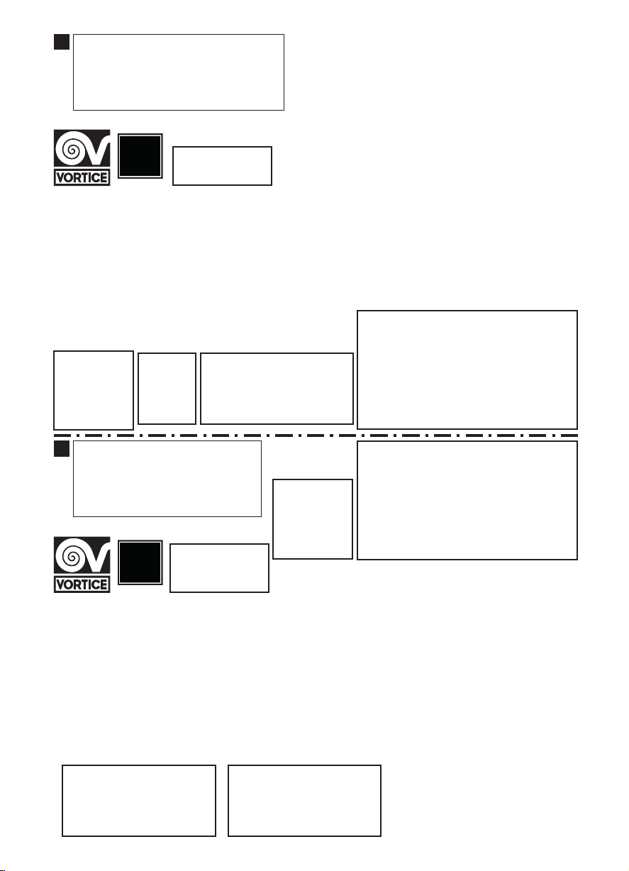
GARANZIA - GUARANTEE - GARANTIE
ANNI
YEARS
2
ANNI
YEARS
2
1
DA CONSERVARE
TO BE RETAINED
A CONSERVER
DATA
DATA - DATE
Esclusioni
La presente garanzia non copre:
• Le rotture provocate dal trasporto.
• I difetti o guasti derivanti da uso non corretto o improprio da parte del cliente.
• I difetti derivanti dal mancato rispetto delle avvertenze e condizioni d’uso
indicate nel libretto di istruzioni ed uso allegato al prodotto.
• I difetti derivanti da non corretta installazione ovvero da una installazione
effettuata senza rispettare quanto previsto nel relativo capitolo del libretto di
istruzioni ed uso.
• I guasti derivanti da un errato allacciamento alla rete di alimentazione elettrica o per tensione di alimentazione diversa da quella prevista per
l’apparecchio, ovvero diversa dal limite stabilito dalle norme CEI (+/- 10% del valore nominale).
La presente garanzia non copre, inoltre, gli eventuali difetti derivanti da una cattiva manutenzione ovvero da interventi effettuati da personale non
qualicato o da terzi non autorizzati.
TIMBRO RIVENDITORE
stamp of supplier
cacher du vendeur
CONF.
----------------COLL.
MAILING DATE - ENVOYÉ PAR LA POSTE LE
Per poter usufruire della garanzia il cliente deve compilare e rispedire alla VORTICE
SPA, entro 8 giorni dall’acquisto, la “Parte 2” del tagliando di garanzia, all’indirizzo
e con le modalità in tale parte riportate.
La “Parte 1” del tagliando di garanzia deve essere conservata e presentata,
unitamente al documento scale (scontrino o fattura) rilasciato dal venditore al
momento dell’acquisto, al Centro di Assistenza autorizzato VORTICE che dovrà
eseguire l’intervento in garanzia.
This warranty must be attached to the appliance should it need to be returned for
servicing.
N.B. Guarantee is only valid if all details are completed correctly.
ATTENTION: pour bénécier de la garantie, le présent certicat doit obligatoirement
accompagner l’appareil présumé défectueux. Le certicat doit porter le cachet du
revendeur et la date d’achat.
A defaut, la garantie sera comptée à partir de la date de sortie d’usine.
SPEDITO IL
GARANZIA - GUARANTEE - GARANTIE
2
DA SPEDIRE
TO SEND (within 8 days from date of purchase)
A RETOURNER (dans les 8 jours après l’achat)
DATI UTENTE / CUSTOMER DATA / COORDONNÉES DE L’UTILISATEUR
nome / name / nom ______________________________________________
cognome / surname / prenom _______________ __________________
via / street / rue __________________________________________________
cap / post code / code postal _____________________________________
città / town ______________________________________________________
Dichiaro di aver preso atto delle condizioni di garanzia specicate sul certicato in mio possesso e autorizzo la gestione dei miei dati personali (v. retro).
I have read and understood the terms and conditions of this guarantee and I authorise the processing of my personal details (see overleaf).
Suivant les conditions de garantie dénies par le certicat en ma possession j’autorise l’utilisation de mes coordonnées (voir au verso).
rma / signature / signature _________________________________
MAILING DATE - ENVOYÉ PAR LA POSTE LE
(entro 8 giorni dall’acquisto)
SPEDITO IL
DATA
DATA - DATE
TIMBRO RIVENDITORE
stamp of supplier
cacher du vendeur
DATE OF PURCHESE - DATE DE L’ACHAT
ACQUISTATO IL
 Loading...