

Page 1
Libretto d’istruzioni
Instruction booklet
Notice de pose et d’entretien
Betriebsanleitung
Folleto de instrucciones
Gebruiksaanwijzing
Instruktionshäfte
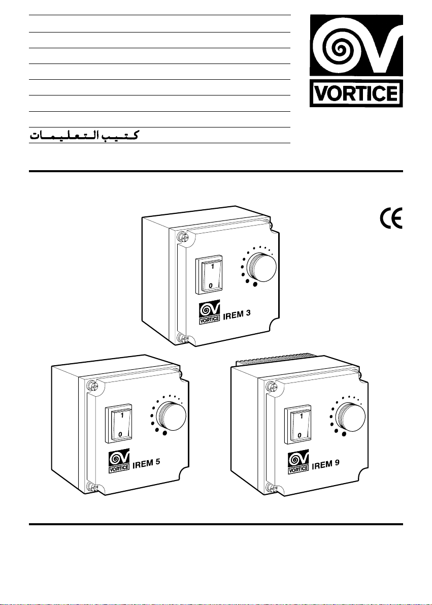
IREM 3 - 5 - 9
IP54
MADE IN ITALY COD. 2/0/00
VORTICELIMITED
Milley Lane - Hare Hatch
Reading - Berkshire - RG10 9TH
Tel. (+ 44) 118-94.04.211
Fax (+44) 118-94.03.787
UNITED KINGDOM
VORTICEFRANCE
72 Rue Baratte-Cholet
94106 Saint Maur Cedex
Tel. (+ 33) 1- 55.12.50.00
Fax (+33) 1-55.12.50.01
FRANCE
VORTICEELETTROSOCIALI S.p.A.
Strada Cerca, 2 - frazione di Zoate
20067 TRIBIANO (MI)
Tel. (+ 39) 02-90.69.91
Fax (+39) 02-90.64.625
ITALIA
Page 2

2
Indice
Descrizione e impiego. . . . . . . . . . . . . . . 4
Attenzione . . . . . . . . . . . . . . . . . . . . . . . 6
Avvertenza . . . . . . . . . . . . . . . . . . . . . . . 6
Installazione - Regolazione trimmer . . . . 7
Index
Description and use . . . . . . . . . . . . . . . . 4
Caution. . . . . . . . . . . . . . . . . . . . . . . . . . 7
Precaution . . . . . . . . . . . . . . . . . . . . . . . 7
Installation - Regulator trimmer . . . . . . . 21
Sommaire
Description et mode d’emploi . . . . . . . . . 4
Attention. . . . . . . . . . . . . . . . . . . . . . . . . 9
Notice. . . . . . . . . . . . . . . . . . . . . . . . . . . 9
Installation - Réglage trimmer . . . . . . . . 21
Inhalt
Beschreibung und Anwendung . . . . . . . . 4
Achtung . . . . . . . . . . . . . . . . . . . . . . . . 11
Hinweis. . . . . . . . . . . . . . . . . . . . . . . . . 11
Installation - Einstellung trimmer . . . . . . 21
Avant d’utiliser le produit et de le connecteur,
lire attentivement ces instructions.Vortice ne
pourra être tenu pour responsable des
dommages éventuels causés aux personnes ou
aux choses par suite du non respect de ce qui
est présénté dans le présent livret.
Le respect de toutes les indications reportées
dans ce livret garantira une longue durée de vie
ainsi que la fiabilité électrique et mécanique de
cet appareil.
Conserver toujours à portée de main le présent
livret d’instructions
Bevor das Gerät montiert und angeschlossen
wird, diese Anleitung genau durchlesen. Vortice
kann nicht für Personen- oder Sachschäden zur
Verantwortung gezogen werden, die auf eine
Nichtbeachtung der Hinweise in dieser
Betriebsanleitung zurückzuführen sind.
Befolgen Sie alle Anweisungen, um eine lang e
Lebensdauer, sowie die elektrische und
mechanische Zuverlässigkeit des Geräts zu
gewährleisten.
Diese Betriebsanleitung ist gut aufzubewahren.
Before installing and connecting the unit,
carefully read these instructions.Vortice cannot
assume any responsibility for damage
to property or personal harm resulting from
failure to abide by the conditions given
in this booklet.
Following these instructions will assure long
service life and overall electrical and
mechanical reliability.
Keep this instruction booklet in safe place.
Prima di installare e collegare il prodotto,
leggere attentamente queste istruzioni.Vortice
non può essere considerata responsabile per
eventuali danni a persone o cose causate
dalla non applicazione di quanto contenuto
nel libretto.
Seguire tutte le istruzioni per assicurare
la sua durata, la sua affidabilità elettrica
e meccanica.
Conservare sempre questo libretto d’istruzioni.
Indice
Descripción y empleo . . . . . . . . . . . . . . . 4
Atención. . . . . . . . . . . . . . . . . . . . . . . . 13
Advertencia . . . . . . . . . . . . . . . . . . . . . 13
Instalación - Regulación trimmer. . . . . . 21
Antes de instalar y conectar el producto, leer
atentamente estas instrucciones.Vortice no
puede ser considerada responsable por
eventualese daños a personas o cosas
causados por la falta de aplicación de lo
contenido en este folleto.
Seguir todas estas indicaciones para
asegurar su duración y su eficiencia eléctrica
y mecánica.
Conservar siempre esta folleto de
instrucciones.
Page 3
3
Inhoudsopgave
Beschrijving en gebruik . . . . . . . . . . . . . . 4
Let op. . . . . . . . . . . . . . . . . . . . . . . . . . 15
Waarschuwing . . . . . . . . . . . . . . . . . . . 15
Installatie - Regeling trimmer. . . . . . . . . 21
Innehållsföreckning
Beskrivning. . . . . . . . . . . . . . . . . . . . . . . 4
Varning. . . . . . . . . . . . . . . . . . . . . . . . . 17
Obs . . . . . . . . . . . . . . . . . . . . . . . . . . . 17
Installation - Reglering av trimmer. . . . . 21
4
19
19
21
Lees deze handleiding aandachting door
alvorens het product te plaatsen en aan te
sluiten.Vortice kan niet aansprakelijk worden
gesteld voor eventuele schade aan personen of
zaken, ontstaan als g evolg van het niet in acht
nemen vande sanwijzingen in dit boekje.
Volg de instructies nauwkeuring opdat;
dat komt de levensduur en de betrouwbaarheid
van de elektrische en mechanische
componenten ten goede.
Läs noga dessa anvisningar innan produkten
installeras och ansluts. De ger värdefull
information om installattion, användning och
underhål .Vortice kan ej hållas ansvarig för
eventuella skador på person eller föremål som
orsakats av att vad denna bruksanvisning inte
har beaktats.
Följ alla dessa instruktioner för att garantera
produktens livslängd och dess elektriska och
mekaniska pålitlighet.
Spara detta häfte för framtida behov.
Page 4

4
DESCRIZIONE E IMPIEGO
I dispositivi denominati IREM 3, IREM 5 ed IREM 9
sono apparecchi ad alta tecnologia e costruiti a regola
d’arte, destinati alla regolazione manuale di uno o più
motori, monofase o comunque contraddistinti da
carico ohmico-induttivo, caratterizzati da intensità
massima complessiva di corrente non superiore
rispettivamente a 3, 5 e 9 A. La tabella a pag. 6 indica
gli accoppiamenti regolatore-singolo prodotto
(industriale). Si noti che il modello IREM 9 è
specificamente destinato alla regolazione simultanea
di più apparecchi.
I dispositivi IREM non sono adatti alla regolazione di
carichi di tipo capacitativo.
Una spia luminosa, conglobata nell’interruttore
bipolare, segnala la presenza di tensione sul carico.
I regolatori sono altresì dotati di potenziometro per la
regolazione della tensione sino ad un valore minimo,
preimpostabile mediante apposito trimmer.
Il modello IREM 9 è inoltre provvisto di dissipatore
alettato destinato a migliorare lo smaltimento termico.
Description and use
The IREM 3, IREM 5 AND IREM 9 are high-tech,
state-of-the-art manual regulators for operation with
one or more single-phase ohmic-inductive load
electric motors with maximum overall current ratings
of 3, 5 and 9 amperes respectively. The table on
page 6 shows the couplings between the regulators
and the individual industrial products. As can be seen,
the IREM 9 is specifically designed for regulating
several motors simultaneously.
These IREM regulators are not designed for
regulating capacitance type loads.
The two-pole switch incorporates an indicator light
that turns on when the load is under voltage.
Each regulator also has a potentiometer for adjusting
voltage down to a minimum value, depending on the
trimmer setting.
The IREM 9 regulator is also provided with a fin-type
dissipater for improving heat dissipation.
Description et mode d’emploi
Les dispositifs appelés IREM 3, IREM 5 et IREM 9
sont des appareils à haute technologie, construits
dans les règles de l’art, destinés au réglage manuel
d’un ou plusieurs moteurs, monophasés, ou de toute
façon qui se distinguent par une charge ohmiqueinductive et se caractérisent par une intensité
maximum totale de courant non supérieure à 3, 5 et 9
A respectivement.La table reportée à la page 5 indique
les couplages régulateur-produit individuel (industriel).
Note: le modèle IREM 9 est spécifiquement destiné
au réglage simultané de plusieurs appareils.
Les dispositifs IREM ne sont pas adaptés au réglage
de charges de type capacitatif.
Un voyant lumineux englobé dans l’interrupteur
bipolaire signale la présence de tension sur la charge.
Les régulateurs sont eux aussi munis d’un
potentiomètre pour le réglage de la tension jusqu’à
une valeur minimum à fixer préalablement au moyen
d’un trimmer prévu à cet effet.
Le modèle IREM 9 est aussi muni d’un dissipateur à
ailettes destiné à en améliorer le refroidissement.
Beschreibung und Einsatz
Die benannten Vorrichtungen IREM 3, IREM 5 und
IREM 9 sind Hochtechnologieapparate, die nach allen
Regeln der Kunst konstruiert werden. Sie sind zur
manuellen Regulierung eines oder mehrerer Motoren
bestimmt, welche einphasig sind oder durch ohmischinduktive Last und durch eine
Gesamthöchststromstärke von 3, 5 und 9 A
gekennzeichnet sind.Die Tabelle auf Seite 6 zeigt die
Verbindung Regulator – Einzelprodukt (industriell) an.
Das Modell IREM 9 ist eigens dafür geschaffen, die
simultane Regulierung mehrerer Apparate zu
übernehmen.
Die Vorrichtungen IREM sind nicht für eine kapazitive
Regulierung geeignet.
Eine im zweipoligen Schalter integrierte
Anzeigelampe deutet das Vorhandensein von
Lastspannung an.
Die Regler sind außerdem mit Potentiometern zur
Spannungsregulierung bis auf einen Minimalwert, der
mittels entsprechenden Trimmern eingestellt wird,
ausgerüstet.
Das Modell IREM 9 ist darüber hinaus mit einem
Kühlkörper versehen, der die thermische
Wärmeableitung verbessert.
Descripción y empleo
Los dispositivos denominados IREM 3, IREM 5 e
IREM 9 son aparatos de alta tecnología construidos a
regla de arte, destinados a la regulación manual de
uno o varios motores, monofásicos o caracterizados
por carga ohmica-inductiva, con una intensidad
máxima total de corriente no superior a 3, 5 y 9 A
respectivamente.La tabla de la pág.6 indica los
acoplamientos regulador-producto (industrial). Se hace
notar que el modelo IREM 9 está específicamente
destinado a la regulación simultánea de varios
aparatos.
Los dispositivos IREM no son aptos para la
regulación de cargas de tipo capacitativo.
Un indicador luminoso, incorporado en el interruptor
bipolar, señala la presencia de tensión sobre la carga.
Los reguladores están además dotados de
potenciómetro para la regulación de la tensión hasta
un valor mínimo programable mediante trimmer.
El modelo IREM 9 está además provisto de disipador
con aletas destinado a mejorar la eliminación térmica.
Beschrijving en gebruik
De inrichtingen genoemd IREM 3, IREM 5 e IREM 9
zijn technologisch hoogwaardige, met grote vakkennis
vervaardigde apparaten die dienen voor het
handmatig regelen van een of meer motoren,
eenfasige of hoe dan ook gekenmerkt door
inductieve ohmse belasting, waarvan de totale
maximale stroomsterkte resp. de 3, 5 en 8 A niet
overschrijdt.De tabel op pag. 6 geeft de betreffende
gegevens ter regeling van het afzonderlijke
(industriële) product aan. Let erop dat model IREM 9
speciaal is bestemd voor de gelijktijdige regeling van
meerdere apparaten.
De IREM-inrichtingen zijn niet geschikt voor het
regelen van belastingen van het capacitieve soort.
Een rood LED dat zich in de tweepolige schakelaar
Page 5
5
bevindt, signaleert de aanwezigheid van spanning op
de belasting.
De regelinrichtingen zijn tevens voorzien van een
potentiemeter voor de regeling van de spanning tot
een minimumwaarde, vooraf ingesteld met een
speciale trimmer.
Het model IREM 9 is bovendien voorzien van een
warmteafvoerinrichting met schoepen voor het beter
afvoeren van de warmte.
Beskrivning och användning
Anordningarna benämnda IREM 3, IREM 5 och IREM
9 är högteknologiska apparater och konstruerade på
ett korrekt sätt.De är utrustade med manuell reglering
av en eller flera motorer, med en en-fas nätspänning
eller i vilket fall som helst med en ohmsk-induktiv
belastning, samt med en maximal total strömstyrka på
högst 3,5 och 9 A.Tabellen på sidan 6 visar
anslutningarna regulator-enskild produkt (industriell).
Observera att modellen IREM 9 är avsedd för
simultan reglering av flera apparater.
Anordningarna IREM är inte lämpliga för kapacitiv
belastningsreglering.
En kontrollampa, inbyggd i den bipolära brytaren,
signalerar förekomsten av spänning på belastningen.
Regulatorerna är likaledes försedda med
potentiometer, förprogrammerbar medelst den
avpassade Trimmern, för regleringen av spänningen
till ett minimi värde.
Modellen IREM 9 är dessutom utrustad med kylare,
avsedd att justera värmedeponeringen.
Page 6
Mod. Cod.
E 252 M 40.203
E 254 M 40.303
E 302 M 40.403
E 304 M 40.503
E 354 M 40.703
220 - 240 V
E 404 M 40.903
IREM 3 (cod. 12.931)
E 454 M 41.153
E 504 M 41.219
E 604 M 41.459
MP 252 M 42.252
220 - 240 V
MP 304 M 42.204
IREM 3 (cod. 12.931)
MP 354 M 42.214
MP 404 M 42.224
MPC 252 M 42.253
220 - 240 V
MPC 304 M 42.205
IREM 3 (cod. 12.931)
MPC 354 M 42.215
MPC 404 M 42.225
TRM 10 E 15.115
TRM 15 E 15.205
IREM 3 (cod. 12.931)220 - 240 V
TRM 10 15.100
TRM 15 15.200
TRM 20 ED 15.050
230 V TRM 30 ED 15.052
IREM 3 (cod. 12.931)
TRM 50 ED 15.504 IREM 5 (cod. 12.932)
6
Page 7
ITALIANO
• Non usare questo prodotto per una funzione
differente da quella esposta in questo libretto.
• Dopo aver tolto il prodotto dal suo imballo,
assicurarsi della sua integrità: nel dubbio rivolgersi
subito ad un Centro Assistenza Vortice. Non lasciare
le parti dell’imballo alla portata di bambini o incapaci.
•L’uso di qualsiasi apparecchio elettrico comporta
l’osservanza di alcune regole fondamentali, tra le quali:
- non deve essere toccato con mani bagnate o umide;
- non deve essere toccato a piedi nudi;
- non deve essere usato da bambini o incapaci.
• Non utilizzare l’apparecchio in presenza di sostanze
o vapori infiammabili come alcool, insetticidi,
benzina, ecc.
• Prima di effettuare il prodotto qualsiasi operazione di
pulizia o manutenzione, spegnere l’interruttore
dell’apparecchio.
• Quando si decide di eliminare definitivamente
l’apparecchio spegnere l’interruttore dell’impianto e
poi scollegare l’apparecchio dalla rete elettrica.
Riporre infine il prodotto in luogo inaccessibile a
bambini o incapaci.
Attenzione: questo simbolo indica precauzioni per evitare danni all’utente
!
• Non utilizzare l’apparecchio in presenza di sostanze
o vapori infiammabili come alcool, insetticidi,
benzina, ecc.
• Prima di effettuare il prodotto qualsiasi operazione di
pulizia o manutenzione, spegnere l’interruttore
dell’apparecchio.
• Quando si decide di eliminare definitivamente
l’apparecchio spegnere l’interruttore dell’impianto e
poi scollegare l’apparecchio dalla rete elettrica.
Riporre infine il prodotto in luogo inaccessibile a
bambini o incapaci.
• Questo apparecchio non è da intendersi adatto all’uso
Avvertenza: questo simbolo indica precauzioni per evitare inconvenienti al prodotto
!
• Non apportare modifiche di alcun genere al prodotto.
• Le possibili applicazioni dell’apparecchio sono
elencate nella tabella di pag. 6. Non tutti i prodotti ivi
menzionati sono commercializzati in tutti i Paesi.
• Non lasciare l’apparecchio esposto ad agenti
atmosferici (pioggia, sole, ecc.).
• Non appoggiare oggetti sull’apparecchio.
• Ispezionare visivamente e periodicamente l’integrità
dell’apparecchio. In caso d’imperfezioni, non
utilizzare l’apparecchio e contattare subito il Centro
Assistenza Vortice
• L’impianto elettrico a cui è collegato il prodotto deve
essere conforme alle norme vigenti.
• L’installazione dell’apparecchio deve essere
effettuata da personale professionalmente
qualificato.
• L’apparecchio deve essere correttamente collegato
ad un efficace impianto di messa a terra, come
previsto dalle vigenti norme di sicurezza elettrica. In
caso di dubbio, richiedere un controllo accurato da
parte di personale professionalmente qualificato.
• Collegare il prodotto alla rete di alimentazione/presa
elettrica solo se la portata dell’impianto/presa è
adeguata alla sua potenza massima. In caso
contrario rivolgersi subito a persona
professionalmente qualificata.
• All’installazione occorre prevedere un interruttore
onnipolare magnetotermico con distanza di apertura
dei contatti uguale o superiore a mm 3.
• Se il prodotto cade o riceve forti colpi farlo verificare
subito presso un Centro di Assistenza Tecnica
autorizzato.
• In caso di cattivo funzionamento e/o guasto,
spegnere l’interruttore dell’apparecchio. Rivolgersi
quindi subito ad un Centro di Assistenza Tecnica
autorizzato e richiedere, per l’eventuale riparazione,
l’uso di ricambi originali Vortice.
• Spegnere l’interruttore dell’apparecchio quando non
è utilizzato.
Regolazioni trimmer
Con il potenziometro sul valore minimo e l’interruttore
acceso ruotare il trimmer in direzione - sino al punto
di fine corsa, quindi ruotarlo in direzione + fino al
raggiungimento della velocità minima desiderata
nell’intervallo di regolazione.
ATTENZIONE:
• Il prodotto garantisce un grado di protezione IP54
solo se l’installazione è effettuata seguendo tutte le
istruzioni di questo libretto.
• L’utilizzo di altro tipo di regolatori può comportare
irregolarità nel funzionamento, nella regolazione e
nella rumorosità dell’apparecchio comandato.
• Nel caso di torrette TRM 10 e TRM 15, il dispositivo
di regolazione dovrà essere collegato alla torretta
nella configurazione di massima velocità.
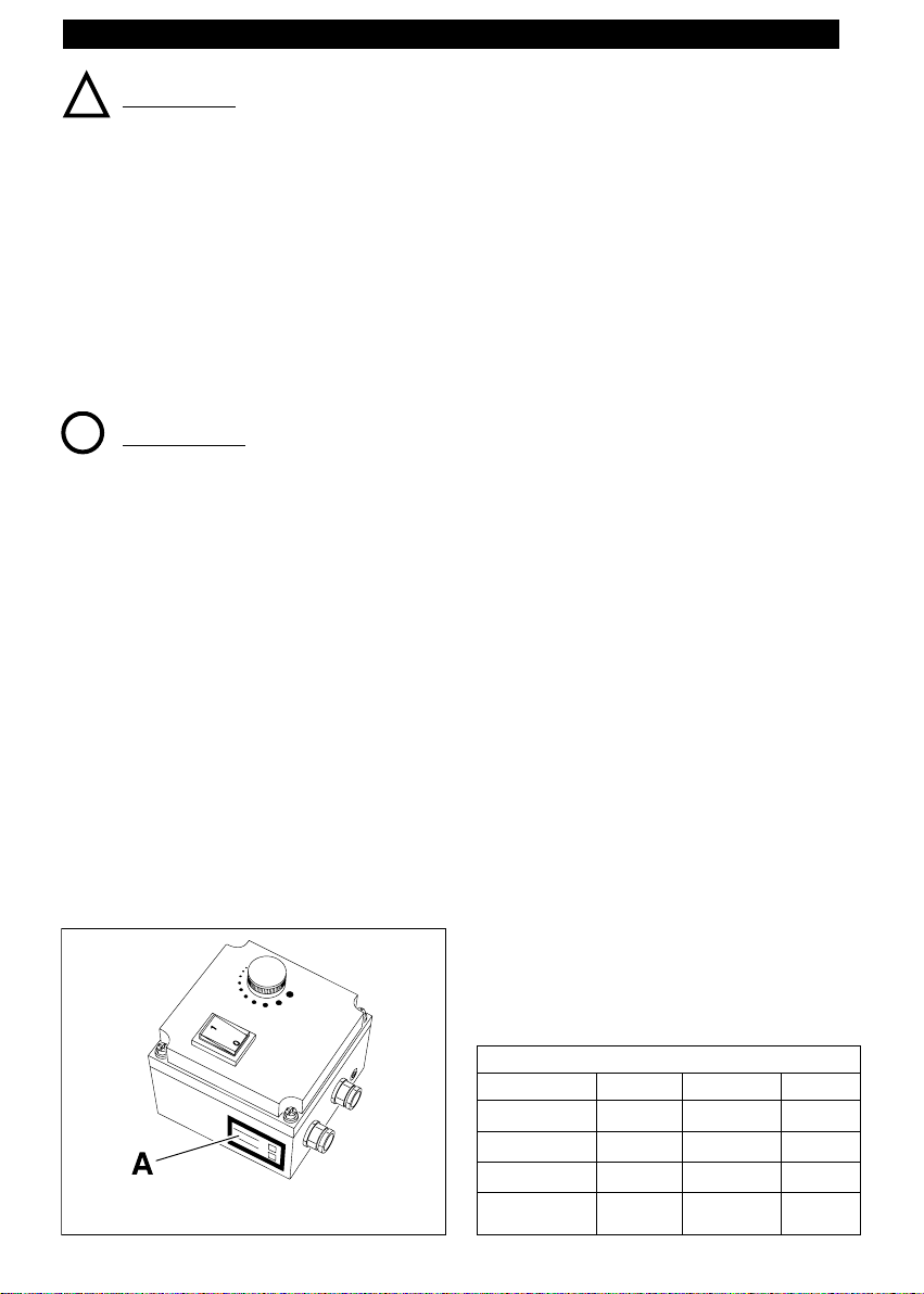
I dati elettrici della rete deve corrispondere a
quelli riportati in targa A.
CARATTERISTICHE TECNICHE
IREM 3 IREM 5 IREM 9
Tensione (V) 220-240 220-240 220-240
Frequenza (Hz) 50 50 50
Corrente max (A) 3 5 9
Temperatura
di lavoro (°C) -10÷+40 -10÷+40 -10÷+40
da parte di persone (inclusi bambini) con ridotte capacità fisiche, sensoriali o mentali, o comunque prive di
esperienza e conoscenza, a meno che siano supervisionate o preventivamente istruite riguardo al suo uso
da persona responsabile della loro sicurezza. I bambini dovrebbero essere supervisionati per assicurarsi
che non giochino con l’apparecchio.
I dati elettrici della rete devono corrispondere a
quelli riportati in targa A.
7
Page 8
8
ENGLISH
• Do not use this product for any purpose other than
for one indicated in this booklet.
• After removing the product from its packing,
check it to see that it has not been damaged in
any way. When in doubt, contact your Vortice
Assistance Center. Do not leave loose packing
materials within reach of children or inexperienced
persons.
• The use or handling of any electrical appliance or
unit requires taking certain precautions:
- Never touch the equipment when your hands are
wet or humid.
- Never touch the equipment if you are barefoot.
- Do not let the equipment be used by children or
inexperienced persons.
• Do not operate the equipment in the presence of
inflammable materials such as alcohol, insecticide,
gasoline (petrol), etc.
• Before performing any cleaning or maintenance
operations on the equipment, disconnect it from the
power source.
• When the equipment is to be permanently removed,
first turn off the main switch and then disconnect it
from the power source.Store the equipment in a
place which is well out of reach of children and
inexperienced persons.
Caution:this symbol indicates that care must be taken to avoid injury
!
Precaution:
this symbol indicates that care must be taken to avoid damaging your product
!
• Do not make any modifications of any kind on the
product.
• The table on page 6 lists all the possible
applications of the unit. Some of the products
mentioned are not sold in all countries.
• Do not allow the unit to be exposed to the sun or
weather (rain, etc.).
• Do not rest any objects on the unit.
• Perform periodic visual inspection to check for
defects.If any are found, do not operate the unit and
immediately contact your Vortice Assistance Center.
• The power mains to which the unit is connected
must conform to the existing norms.
• Installation of the unit must only be done by a
qualified technician.
• The unit must be correctly connected to an efficient
grounding system, as prescribed by the existing
safety norms. When in doubt, have the system
carefully inspected by a qualified technician.
• Before connecting the unit to a power source, check
to make sure the power source meets the maximum
power requirements of the unit.If it does not,
immediately contact a qualified technician.
• When installing the unit, an omnipole, magnetothermal switch must also be installed. The switch
contact gaps must measure at least 3 mm.
• If the unit is dropped or receives a hard blow, have
the unit immediately checked at an authorized
Technical Assistance Center.
• If the unit develops a malfunction or operates
improperly, turn it off and immediately contact an
authorized Technical Assistance Center. If any parts
need replacing, be sure to request the use of
original Vortice spare par ts.
• When the unit is not being operated, turn off its
main switch.
Trimmer Adjustment
Turn on the unit. Turn the potentiometer in the “–“
direction until it stops turning. Now rotate it in the “+”
direction until the desired minimum speed-regulation
interval is obtained.
A TTENTION:
• IP54 protection for the unit can be guaranteed only if
all the installation instructions given in this booklet
are carefully followed.
• Using a different type of regulator is not advised
because the controlled unit may function improperly
or be improperly regulated, and it may also operate
very noisily.
• The regulating unit on the TRM 10 and TRM15
turrets must be connect to the turret in the maximum
speed configuration.
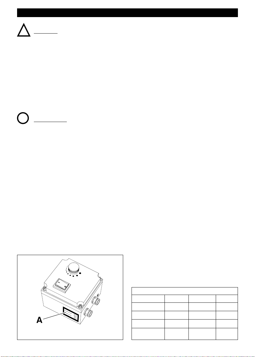
The power-source data must be consistent with
the electrical data shown on the name plate A.
TECHNICAL CARACTERISTICS
IREM 3 IREM 5 IREM 9
Voltage (V) 220-240 220-240 220-240
Frequency (Hz) 50 50 50
Max Current (A) 3 5 9
Operating
temp.range (°C) -10÷+40 -10÷+40 -10÷+40
Page 9

9
FRANÇAIS
• Ne pas utiliser ce produit pour une fonction autre
que celle exposée dans ce livret.
• Une fois le produit débarrassé de son emballage,
s’assurer qu’il est intact. En cas de doute,
s’adresser immédiatement à un Centre
d’Assistance Vortice. Ne pas abandonner de
parties d’emballage à por tée des enfants ou de
handicapés.
• L’utilisation de tout appareil électrique requiert le
respect de quelques règles fondamentales, à
savoir:
- ne pas le toucher les mains mouillées ou humides
- ne pas le toucher pieds nus
- ne pas le laisser utiliser par des enfants ou des
handicapés.
• Ne pas se servir de l’appareil en présence de
substances ou de vapeurs inflammables, comme
l’alcool, les insecticides, l’essence, etc…
• Avant toute opération de nettoyage ou de
maintenance sur le produit, éteindre l’interrupteur
de l’appareil.
• Quand on décide d’éliminer l’appareil
définitivement, éteindre l’interrupteur de
l’installation puis débrancher l’appareil du secteur.
Mettre enfin le produit dans un endroit inaccessible
aux enfants ou aux handicapés.
Attention: ce symbole indique la nécessité de quelques précautions pour la sécurité
de l’utilisateur
!
Notice: ce symbole indique la nécessité de quelques précautions pour la sécurité
du produit
!
• Ne pas faire de modifications de quelque genre que
ce soit sur l’appareil.
• Les applications de l’appareil sont indiquées dans la
table de la page 6. Les produits qui y sont
mentionnés ne sont pas tous commercialisables
dans tous les pays.
• Ne pas laisser l’appareil exposé à des agents
atmosphériques (pluie, soleil, etc…).
• Ne pas poser d’objets sur l’appareil.
• Procéder périodiquement à une inspection visuelle de
l’appareil pour en contrôler l’intégrité. Si on découvre
des imperfections ne pas utiliser l’appareil et contacter
immédiatement le Centre d’Assistance V ortice.
• L’installation électrique à laquelle est connecté le
produit doit être conforme aux normes en vigueur.
• L’installation de l’appareil doit être faite par du
personnel professionnellement qualifié.
• L’appareil doit être correctement connecté à une
installation de mise à la terre efficace, comme prévu
par les normes de sécurité électrique en vigueur. En
cas de doute, demander un contrôle approfondi à du
personnel professionnellement qualifié.
• Connecter le produit au secteur/prise de courant
uniquement si la capacité de l’installation/prise de
courant est capable d’en supporter la puissance
maximum. Dans le cas contraire s’adresser
immédiatement à du personnel professionnellement
qualifié.
• Prévoir à l’installation un interrupteur omnipolaire
magnétothermique avec distance d’ouverture des
contacts égale ou supérieure à 3 mm.
• En cas de chute ou de chocs violents du produit,
faire vérifier immédiatement celui-ci dans un Centre
d’Assistance Technique autorisé.
• En cas de mauvais fonctionnement et/ou de panne,
éteindre l’interrupteur de l’appareil puis contacter
immédiatement un Centre d’Assistance Technique
autorisé et demander, pour la réparation éventuelle ,
d’utiliser des pièces de rechange originales Vortice.
Réglage du trimmer
Avec le potentiomètre réglé à la valeur minimum et
l’interrupteur allumé, tourner le trimmer dans la
direction (–) jusqu’à la butée puis le tourner dans la
direction (+) jusqu’à ce qu’on atteigne la vitesse
minimum désirée dans l’intervalle de réglage.
A TTENTION
• Le produit ne garantit le degré de protection IP54
que si l’installation est faite en suivant toutes les
instructions de ce livret.
• L’utilisation de tout autre type de régulateur peut
provoquer des irrégularités de fonctionnement, de
réglage et sonores de l’appareil commandé.
• En cas de tourelles TRM 10 et TRM 15, le dispositif
de réglage devra être connecté à la tourelle en
configuration de vitesse maximum.
Les informations électriques du réseau
correspondent à celles qui sont reportées sur la
plaque d’identification A.
CARACTERISTIQUES TECHNIQUES
IREM 3 IREM 5 IREM 9
Tension (V) 220-240 220-240 220-240
Fréquence (Hz) 50 50 50
Courant max (A) 3 5 9
Température
de service (°C) -10÷+40 -10÷+40 -10÷+40
Page 10

10
DEUTSCH
• Dieses Gerät nicht für V erwendungszwec ke
einsetzen, die in der vorliegenden
Bedienungsanleitung nicht beschrieben sind.
• Nach dem Entfernen des Verpackungsmaterials, ist
der Artikel auf Unversehrtheit zu überprüfen:
wenden Sie sich im Zweifelsfall unverzüglich an eine
autorisierte Vortice-Kundendienststelle.Das
Verpackungsmaterial von Kindern und unbefähigten
Personen fernhalten.
• Beim Einsatz jeglicher Elektrogeräte sind einige
Grundregeln stets zu beachten, darunter im einzelnen:
- niemals mit nassen oder feuchten Händen berühren;
- niemals berühren, wenn Sie barfuss sind;
- niemals von Kindern oder unbefähigten Personen
benutzen lassen.
• Verwenden Sie das Gerät nicht in der Nähe
entflammbarer Substanzen oder deren Dämpfe oder
Ausdünstungen wie Alkohol, Insektizide, Benzin usw.
• Das Gerät vor Ausführung jeglicher Reinigungsoder Wartungsarbeiten mit dem Schalter
ausschalten und den Netzstecker (sofern
vorhanden) ziehen.
• Wenn Sie das Gerät abmontieren und nicht mehr
benutzen wollen, stellen Sie den Hauptschalter der
Elektroanlage ab und lösen Sie das Gerät dann vom
Stromnetz. Das Gerät schließlich an einem Ort
aufbewahren, der für Kinder und unbefähigte
Personen unzugänglich ist.
Achtung:dieses Symbol mahnt zur Vorsicht, um Schäden am Benutzer auszuschließen
!
Hinweis:
dieses Symbol zeigt Vorsichtsmaßnahmen an, um Schäden am Gerät zu vermeiden
!
• Keine V eränderungen jeglicher Art am Gerät
vornehmen.
• Die vorgesehenen Einsatzmöglichkeiten des Apparats
sind in der Tabelle auf Seite 6 aufgelistet.Nicht jedes
darin aufgeführte Produkt wird in alle Länder verkauft.
• Das Gerät keinen Witterungseinwirkungen (Regen,
Sonneneinstrahlung usw.) aussetzen.
• Sich nicht auf das Gerät setzen und keine
Gegenstände darauf abstellen.
• Periodisch die Unversehrtheit augenscheinlich
überprüfen. Im Schadensfall das Gerät nicht
benützen und sofort eine autorisierte VorticeKundendienststelle aufsuchen.
• Die Stromnetz, an dem das Gerät angeschlossen
wird, muss den gültigen Normen entsprechen.
• Die Installation des Gerätes darf nur von
qualifiziertem Personal ausgeführt werden.
• Das Gerät ist sachgerecht mit einer wirksamen
Erdung zu verbinden, so wie es von den einschlägigen
elektrotechnischen Sicherheitsbestimmungen
gefordert wird. Lassen Sie im Zweifelsfall eine
sorgfältige Kontrolle der Elektroanlage durch
qualifiziertes Fachpersonal vornehmen.
• Das Gerät nur dann an das Stromnetz/Steckdose
anschließen, wenn das Stromnetz/Steckdose für die
maximale Leistung des Gerätes ausgelegt ist. Sich
im gegenteiligen Fall sofort an qualifiziertes
Fachpersonal wenden.
• Bei der Installation ist ein allpoliger, thermomagnetischer
Schalter mit einer Kontaktöffn ungsweite von mindestens
3 mm vorzusehen.
• Wenn der Artikel einen Fall oder starke Stöße
erleiden sollte, lassen Sie ihn unverzüglich von einer
autorisierten Kundendienststelle überprüfen.
• Das Gerät im Störungsfall oder bei mangelhafter
Funktion mit dem Schalter ausschalten.Wenden Sie
sich unverzüglich an eine autorisierte
Kundendienststelle und verlangen Sie im Fall einer
notwendigen Reparatur den Einsatz von VORTICE
Original- Ersatzteilen.
• Das Gerät nicht unnötig eingeschaltet lassen.Schalten
Sie es am Schalter aus, wenn es nicht benutzt wird.
Einstellung des Trimmers
Mit dem auf den minimalen Wert eingestellten
Potentiometer und eingeschaltetem Schalter den
Trimmer bis zum Anschlag in die Richtung - drehen;
ihn dann in Richtung + drehen, bis die gewünschte
Minimalgeschwindigkeit im Regulationsbereich
erreicht wird.
ACHTUNG:
• Das Gerät garantiert nur dann einen Schutzgrad von
IP54, wenn bei der Installation alle Anweisungen
dieser Beschreibung eingehalten wurden.
• Der Gebrauch anderer Reglertypen kann Funktions,
Regulations- und Geräuschunregelmäßigkeiten des
betriebenen Geräts verursachen.
• Bei den Säulen TRM 10 und TRM 15 muss die
Regulierungseinheit an die Säule mit der maximalen
Geschwindigkeitskonfiguration verbunden sein.
Die elektrischen daten des Stromnetzes müssen
denen des Schildes A entsprechen.
TECHNISCHE EIGENSCHAFTEN
IREM 3 IREM 5 IREM 9
Spannung (V) 220-240 220-240 220-240
Frequenz (Hz) 50 50 50
max. Strom (A) 3 5 9
Betriebstemperatur
(°C) -10÷+40 -10÷+40 -10÷+40
Page 11

11
ESPAÑOL
• No usar este producto para una función diferente de
la expuesta en este folleto.
• Después de haber sacado el producto de su
embalaje, comprobar su integridad: en caso de
duda dirigirse inmediatamente a un Centro
Asistencia Vortice. No dejar las partes del embalaje
al alcance de niños o incapaces.
• El uso de cualquier aparato eléctrico implica el respeto
de algunas reglas fundamentales, entre las cuales:
- no debe ser tocado con las manos mojadas o
húmedas;
- no debe ser tocado con los pies descalzos
- no debe ser usado por niños o incapaces
• No utilizar el aparato en presencia de substancias o
vapores inflamables tales como alcohol,
insecticidas, bencina, etc.
• Antes de efectuar sobre el producto cualquier
operación de limpieza o manutención, apagar el
interruptor del aparato.
• Cuando se decida eliminar definitivamente el
aparato apagar el interruptor de la instalación y
luego desconectar el aparato de la red eléctrica.
Finalmente, colocar al producto en un lugar fuera
del alcance de niños o incapaces.
Atención:este símbolo indica precauciones para evitar daños al usuario
!
Advertencia:este símbolo indica precauciones para evitar daños al producto
!
• No aportar modificaciones de ningún tipo al producto.
• Las posibles aplicaciones del aparato están
enunciadas en la tabla de la pág.6. No todos los
productos allí mencionados son comercializados en
todos los países.
• No dejar el aparato expuesto a los agentes
atmosféricos (lluvia, sol, etc.).
• No apoyar objetos sobre el aparato.
• Controlar visual y periódicamente la integridad del
aparato; en caso de imperfecciones no utilizarlo y
dirigirse inmediatamente al Centro Asistencia Vortice.
• La instalación eléctrica a la cual está conectado el
producto debe ser conforme a las normas vigentes.
• La instalación del aparato debe ser efectuada por
personal profesionalmente cualificado.
• El aparato debe estar correctamente conectado a una
eficaz instalación de puesta a tierra, según lo previsto
por las normas de seguridad eléctrica vigentes. En
caso de duda, solicitar un cuidadoso control por parte
de personal profesionalmente cualificado.
• Conectar el producto a la red de
alimentación/tomacorrientes eléctrico sólo si la
capacidad de la instalación/tomacorrientes es
adecuada a su potencia máxima. De lo contrario
dirigirse inmediatamente a una persona
profesionalmente cualificada.
• Para la instalación es necesario contar con un
interruptor omnipolar magnetotérmico con distancia
de apertura de los contactos igual o superior a 3 mm.
• Si producto se cae o recibe fuertes golpes hacerlo
controlar inmediatamente en un Centro de
Asistencia Técnica autorizado.
• En caso de mal funcionamiento y/o desperfectos,
apagar el interruptor del aparato.Dirigirse
inmediatamente a un Centro de Asistencia Técnica
autorizado y solicitar, para la eventual reparación,
el uso de repuestos originales Vortice.
• Apagar el interruptor del aparato cuando éste no se
utiliza.
Regulación trimmer
Con el potenciómetro sobre el valor mínimo y el
interruptor encendido, girar el trimmer en dirección –
hasta el punto de tope y luego girarlo en dirección +
hasta alcanzar la velocidad mínima deseada en el
intervalo de regulación.
A TENCION:
• El producto garantiza un grado de protección IP54
sólo si la instalación se efectúa siguiendo todas las
instrucciones de este folleto.
• La utilización de otro tipo de reguladores puede
causar irregularidades en el funcionamiento, en la
regulación y en el nivel de ruido del aparato
accionado.
• En el caso de torretas TRM 10 y TRM 15, el
dispositivo de regulación debe ser conectado a la
torreta en la configuración de máxima velocidad.
Los datos eléctricos de la red corresponden
con los señalados en la placa de características
eléctricas A
CARACTERISTICAS TÉCNICAS
IREM 3 IREM 5 IREM 9
Tensión (V) 220-240 220-240 220-240
Frecuencia (Hz) 50 50 50
Corriente max (A) 3 5 9
Temperatura
de trabajo (°C) -10÷+40 -10÷+40 -10÷+40
Page 12

12
NEDERLANDS
• Gebruik het product niet voor andere doeleinden dan
waarvoor het volgens de handleiding is vervaardigd.
• Controleer, na het verpakkingsmateriaal te hebben
verwijderd, of het product compleet en
onbeschadigd is.Wend u in geval van twijfel tot een
Vortice-Servicecentrum. Houd het
verpakkingsmateriaal buiten het bereik van kinderen
of onbevoegden.
• Bij het gebruik van elektrische apparaten moeten
enige basisregels in acht genomen worden en wel:
- Raak het apparaat niet aan met vochtige of natte
handen;
- gebruik het niet als u blootsvoets bent;
- zorg ervoor dat het apparaat niet wordt gebruikt
door kinderen of onbevoegden.
• Gebruik het apparaat niet in aanwezigheid van
ontvlambare stoffen of dampen, zoals alcohol,
insecticiden, benzine, enz.
• Schakel het apparaat uit, alvorens het te reinigen of
een onderhoudsbeurt te geven.
• Indien u besluit het apparaat niet meer te gebruiken,
schakel het dan uit, koppel het los van het
elektriciteitsnet en berg het op buiten het bereik van
kinderen of onbevoegden.
Let op: dit symbool heeft betrekking op de voorzorgsmaatregelen ter voorkoming van
schade aan de gebruiker
!
Waarschuwing: dit symbool heeft betrekking op de voorzorgsmaatregelen ter
voorkoming van schade aan het product
!
• Breng geen veranderingen, van welke aard ook, in
het product aan.
• De mogelijke toepassingen van het apparaat zijn in
de tabel op pag. 6 aangegeven. Niet alle daarin
voorkomende producten zijn in alle landen in de
handel.
• Stel het apparaat nooit bloot aan weersinvloeden
(regen. zon enz.)
• Leg geen voorwerpen op het apparaat.
• Controleer het apparaat regelmatig om te zien of het
intact is. Indien er iets niet in orde is, wend u dan
onmiddellijk tot het Vortice-Servicecentrum.
• Het elektriciteitsnet waarop het apparaat wordt
aangesloten, moet conform de geldende normen zijn.
• Laat het apparaat door een vakman installeren.
• Het apparaat moet op de juiste wijze worden
aangesloten op een goed geaard elektriciteitsnet,
conform de geldende veiligheidsnormen. Laat in
geval van twijfel een controle uitvoeren door een
vakman.
• Sluit het apparaat alleen op het elektriciteitsnet/de
contactdoos aan, indien de stroomsterkte van het
elektriciteitsnet/de contactdoos geschikt is voor het
maximum vermogen van het apparaat.Is dit niet het
geval, raadpleeg dan een vakman.
• Bij de installatie dient u gebruik te maken van een
meerpolige, magnetothermische schakelaar met
een openingsafstand tussen de contactpunten van
ten minste 3 mm.
• Indien het product valt of zware klappen te verduren
krijgt, moet u het onmiddellijk door een erkend
Servicecentrum laten nakijken.
• Mocht het apparaat niet of niet goed functioneren,
schakel het dan uit.Wend u tot een erkend
Servicecentrum en laat, in geval van reparatie, de
onderdelen alleen vervangen door originele Vorticeonderdelen.
• Schakel het apparaat uit wanneer het niet gebruikt
wordt.
Regeling trimmer
Draai, met de potentiemeter in de minimum stand en
het apparaat in werking, de trimmer richting - tot je
niet verder kunt, en draai hem vervolgens richting +
tot de gewenste minimumsnelheid is bereikt.
LET OP:
• De beschermingsgraad IP54 kan uitsluitend worden
gegarandeerd indien de installatie is uitgevoerd met
inachtneming van alle aanwijzingen in dit boekje
• Het gebruik van andere soorten regelaars kan
negatieve gevolgen hebben voor de werking van het
apparaat en het geluid dat het voortbrengt.
• Voor wat de de torens TRM 10 en TRM 15 betreft
moet de regelinrichting worden aangesloten op de
toren in de configuratie van maximum snelheid.
De elektrische gegevens van het lichtnet moeten
overeenkomen met die van het merkplaatje A.
TECHNISCHE KENMERKEN
IREM 3 IREM 5 IREM 9
Spanning (V) 220-240 220-240 220-240
Frequentie (Hz) 50 50 50
Max
stroomsterkte (A) 3 5 9
Werktemperatuur
(°C) -10÷+40 -10÷+40 -10÷+40
Page 13

13
SVENSKA
• Använd aldrig apparaten för annat bruk än det som
anges i detta häfte.
• Sedan apparaten tagits ur sitt emballage, kontrollera
att den är i fullgott skick.Vid tveksamhet bör
hänvändelse genast göras till en av Vortice
auktoriserad serviceverkstad. Lämna aldrig delar av
emballaget inom räckhåll för barn eller obehöriga.
• Användningen av alla elektriska apparater medför
att vissa grundläggande regler måste iakttagas:
- rör inte apparaten om Du har fuktiga eller våta
händer;
- rör inte apparaten när Du är barfota;
- överlåt inte användningen av apparaten till barn
eller annan obehörig person.
• Använd inte apparaten i närvaro av brandfarliga
ämnen eller ångor som t.ex.sprit, insektsmedel,
bensin, etc..
• Före varje åtgärd, såsom t.ex. rengöring eller
underhåll, skall apparaten göras spänningslös
genom bortkoppling från nätet.
• När apparaten tjänat ut rekommenderas att brytaren
slås av och att den försätts i sådant skick att den inte
kan anslutas till elnätet. Skrota den på så vis att den
inte kommer i händerna på barn eller obehöriga.
Varning: denna symbol anger försiktighetsåtgärder som skall vidtagas för att undvika
att användaren utsätts för skador
!
Obs:denna symbol anger försiktighetsåtgärder som skall vidtagas för att undvika
skador på produkten
!
• Utför inga förändringar på produkten.
• I tabellen på sidan 6 anges föreskrifterna om rätt
sätt att installera apparaten.Inte alla här nämnda
produkter finns till försäljning i alla länder.
• Låt inte apparaten utsättas för atmosfäriska
fenomen (regn, sol, etc.).
• Placera inga föremål på apparaten.
• Kontrollera regelbundet att apparaten är i oskadat
skick. I händelse av fel skall apparaten ej användas
och genast lämnas till en av Vortice auktoriserad
serviceverkstad.
• Apparaten skall anslutas till ett för de gällande
normerna godkänt elnät.
• Installationen av apparaten skall utföras av behörig
fackman.
• Apparaten skall anslutas på ett korrekt sätt till ett
effektivt jordningssystem, såsom förutses av
gällande elektriska säkerhetsnormer.I tveksamma
fall begär en noggrann kontroll av behörig fackman.
• Anslut apparaten till elnätet / vägguttaget endast om
elinstallationens / vägguttagets kapacitet klarar
apparatens maximala effekt.Om så inte är fallet bör
hänvändelse göras till behörig fackman.
• Vid installationen behövs en allpolig
temperaturkänslig strömbrytare med ett
öppningsavstånd hos kontakterna som är lika med
eller större än 3 mm.
• Om apparaten utsätts för slag eller stötar, bör den
genast kontrolleras av auktoriserad teknisk
serviceverkstad.
• I händelse av fel och/eller dålig funktion, skall
apparaten stängas av och genast lämnas till en
auktoriserad teknisk serviceverkstad. Kräv att
Vortice originalreservdelar används vid en eventuell
reparation.
• Slå alltid av strömbrytaren när apparaten inte
används.
Trimmer reglering
Med potentiometern inställd på det lägsta värdet och
med brytaren påslagen, vrids Trimmern mot - ända till
ändläge.Därefter vrids den i riktning mot + för att nå
den lägsta önskade hastigheten under
regleringsintervallen.
VARNING:
• Om installationen utförts enligt instruktionerna i det
här häftet kan produkten garanteras ett
skyddsutförande enligt IP54.
• Användningen av en annan typ av regulatorer kan
medföra fel i driftsättet, i regleringen samt vad gäller
bullernivån hos den styrda apparaten.
• Regleringsanordningen hos TRM 10 och TRM 15
tornen, måste vara ansluten till tornet med den
högsta hastighets konfigurationen.
Den aktuella nätspänningen skall motsvara de
data som återges på apparatens märkskylt A.
TEKNISKA EGENSKAPER
IREM 3 IREM 5 IREM 9
Spänning (V) 220-240 220-240 220-240
Frekvens (Hz) 50 50 50
Max ström (A) 3 5 9
Arbetstemperatur
(°C) -10÷+40 -10÷+40 -10÷+40
Page 14

14
!
!
Page 15

1 2
3
15
INSTALLATION - TRIMMER REGULATOR
INSTALLATION - REGLAGE TRIMMER
INSTALLATION - EINSTELLUNG TRIMMER
INSTALACION - REGULACION TRIMMER
INSTALLATIE - REGELING AV TRIMMER
INSTALLATION - REGLERING AV TRIMMER
INSTALLAZIONE - REGOLAZIONE TRIMMER
-
5
4
6
Page 16

9
MONOF ASE 220-240 V
SINGLE-PHASE
MONOPHASÉ
EINPHASIG
MONOFÁSICO
ENFAS
EENFAZIG
16
7
8A
Page 17

17
1110
1312
14
Page 18

Informazione importante per lo smaltimento ambientalmente compatibile
EN
Important information concerning the environmentally compatible disposal of the appliance
FR
Information importante pour l'élimination compatible avec l'environnement
DE
Wichtige Information für den Benutzer zur umweltfreundlichen Entsorgung des Gerätes
ES
Información importante sobre eliminación respetuosa con el medio ambiente
NL
Belangrijke informatie over milieuvriendelijke afvalverwerking
SV
Viktig information för en miljömässigt förenlig kassering
18
Page 19

IT
IN ALCUNI PAESI DELL'UNIONE EUROPEA
QUESTO PRODOTTO NON RICADE NEL CAMPO
DI APPLICAZIONE DELLA LEGGE NAZIONALE DI
RECEPIMENTO DELLA DIRETTIVA RAEE E
QUINDI NON È IN ESSIVIGENTE ALCUN
OBBLIGO DI RACCOLTA DIFFERENZIATA A FINE
VITA.
Attenzione
Questo prodotto è conforme alla Direttiva EU
2002/96/EC.
Il simbolo del cestino barrato riportato
sull’apparecchio indica che il prodotto,
alla fine della propria vita utile, dovendo
essere trattato separatamente dai rifiuti
domestici, deve essere conferito in un
centro di raccolta differenziata per apparecchiature
elettriche ed elettroniche oppure riconsegnato al
rivenditore al momento dell’acquisto di una nuova
apparecchiatura equivalente.
L’utente è responsabile del conferimento
dell’apparecchio a fine vita alle appropriate strutture
di raccolta, pena le sanzioni previste dalla vigente
legislazione sui rifiuti.
L’adeguata raccolta differenziata per l’avvio
successivo dell’apparecchio dismesso al riciclaggio,
al trattamento e allo smaltimento ambientalmente
compatibile contribuisce ad evitare possibili effetti
negativi sull’ambiente e sulla salute e favorisce il
riciclo dei materiali di cui è composto il prodotto.
Per informazioni più dettagliate inerenti i sistemi di
raccolta disponibili, rivolgersi al servizio locale di
smaltimento rifiuti, o al negozio in cui è stato
effettuato l’acquisto.
I produttori e gli importatori ottemperano alla loro
responsabilità per il riciclaggio, il trattamento e lo
smaltimento ambientalmente compatibile sia
direttamente sia partecipando ad un sistema collettivo.
EN
IN CERTAIN EUROPEAN UNION COUNTRIES THIS
PRODUCT DOES NOT FALL WITHIN THE
REQUIREMENTS OF THE NATIONAL LAWS
IMPLEMENTING THE WEEE DIRECTIVE, AND IN
THESE COUNTRIES THE PRODUCT IS NOT
SUBJECTTO SEPARATE DISPOSAL OPERATIONS
AT THE END OF ITS WORKING LIFE.
Important
This product conforms to EU Directive 2002/96/EC.
This appliance bears the symbol of
the barred waste bin. This indicates
that, at the end of its useful life, it
must not be disposed of as domestic
waste, but must be taken to a
collection centre for waste electrical
and electronic equipment, or returned to a retailer on
purchase of a replacement.
It is the user's responsibility to dispose of this
appliance through the appropriate channels at the end
of its useful life. Failure to do so may incur the
penalties established by laws governing waste
disposal.
Proper differential collection, and the subsequent
recycling, processing and environmentally compatible
disposal of waste equipment avoids unnecessary
damage to the environment and possible related
health risks, and also promotes recycling of the
materials used in the appliance.
For further information on waste collection and
disposal, contact your local waste disposal service, or
the shop from which you purchased the appliance.
Manufacturers and importers fulfil their responsibilities
for recycling, processing and environmentally
compatible disposal either directly or by participating
in collective systems.
19
Page 20

FR
DANS CERTAINS PAYS DE L'UNION
EUROPÉENNE, CE PRODUIT NE FAIT PAS PARTIE
DU DOMAINE D'APPLICATION DE LA LOI
NATIONALE D'ASSIMILATION DE LA DIRECTIVE
DEEE ET PAR CONSÉQUENT, IL N'Y EXISTE
AUCUNE OBLIGATION DE COLLECTE
DIFFÉRENCIÉE À LA FIN DE SA DURÉE DE VIE.
Attention
Ce produit est conforme à la directive EU
2002/96/EC.
Le symbole représentant une poubelle
barrée présent sur l'appareil indique qu'à
la fin de son cycle de vie, il devra être
traité séparément des déchets
domestiques.
Il devra donc être confié à un centre de
collecte sélective pour appareils électriques et
électroniques ou rapporté au revendeur lors de l'achat
d'un nouvel appareil.
L'utilisateur est responsable de la remise de l'appareil
usagé aux structures de collecte compétentes sous
peine des sanctions prévues par la législation sur
l'élimination des déchets.
La collecte sélective réalisée avant le recyclage, le
traitement et l'élimination compatible avec l'environnement
de l'appareil usagé contribue à éviter les nuisances pour
l'environnement et pour la santé et favorise le recyclage
des matériaux qui composent le produit.
Pour de plus amples informations concernant les
systèmes de collecte existants, adressez-vous au
service local d'élimination des déchets ou au magasin
qui vous a vendu l'appareil.
Les fabricants et les importateurs optempèrent à leur
responsabilité en matière de recyclage, de traitement et
d'élimination des déchets compatible avec
l'environnement directement ou par l'intermédiaire d'un
système collectif.
DE
IN EINIGEN EU-LÄNDERN GELTEN FÜR DIESES
PRODUKT NICHT DIE VORGABEN DER
EUROPÄISCHEN RICHTLINIE ÜBER ELEKTROUND ELEKTRONIK-ALTGERÄTE (WEEERICHTLINIE) UND DEMNACH BESTEHT IN
DIESEN LÄNDERN AUCH KEINE PFLICHT FÜR
DIE MÜLLTRENNUNG BEI DER ENTSORGUNG
DES GERÄTES.
Achtung
Dieses Gerät entspricht der EG-Richtlinie 2002/96/EG.
Das Symbol mit der durchgestrichenen
Abfalltonne am Gerät bedeutet, dass das
Gerät nach seiner Aussonderung nicht
im Haushaltsmüll entsorgt werden darf,
sondern an einer Sammelstelle für
Elektro- und Elektronikgeräte oder beim
Kauf eines gleichwertigen Neugerätes beim Händler
abzugeben ist.
Der Benutzer hat Sorge zu tragen, dass das Gerät
nach seiner Aussonderung an einer geeigneten
Sammelstelle abgegeben wird. Ein Nichtbeachten
dieser Vorschrift ist gemäß der geltenden
Abfallordnung strafbar.
Das geeignete Sortieren von Abfall und nachfolgende
Recyceln des aussortierten Gerätes zur
umweltverträglichen Entsorgung trägt zum Schutz von
Umwelt und Gesundheit bei und dient der
Wiederverwendung der recyclingfähigen Materialien,
aus denen das Gerät besteht.
Für detailliertere Informationen bezüglich der
verfügbaren Sammelsysteme wenden Sie sich an Ihre
örtliche Behörde oder an den Händler, bei dem Sie
das Gerät gekauft haben.
Die Hersteller und Importeure kommen ihrer
Verpflichtung zum umweltfreundlichen Recycling,
Verarbeiten und Entsorgen sowohl direkt als auch
durch Teilnahme an einem Kollektivsystem nach.
20
Page 21

ES
EN ALGUNOS PAÍSES DE LA UNIÓN EUROPEA
ESTE PRODUCTO NO ESTÁ INCLUIDO EN EL
ÁMBITO DE APLICACIÓN DE LA LEY NACIONAL
QUE TRASPONE LA DIRECTIVA RAEEY, POR LO
TANTO, NO EXISTE OBLIGACIÓN ALGUNA DE
RECOGIDA SELECTIVA AL FINALIZAR SU VIDA
ÚTIL.
Atención
Este producto cumple los requisitos de la Directiva
EU 2002/96/EC.
El símbolo del contenedor de basura
tachado, que hay sobre el aparato, indica
que no puede ser eliminado con los
desechos domésticos al finalizar su vida
útil. Se ha de llevar a un punto de recogida
selectiva para aparatos eléctricos o
electrónicos o entregar al proveedor durante la compra
de un aparato equivalente.
El usuario deberá llevar el aparato a un punto de
recogida selectiva para su eliminación, de lo contrario
se aplicarán las sanciones previstas por las normas
sobre eliminación de desechos.
La recogida selectiva para la reutilización, tratamiento
y eliminación respetuosa con el medio ambiente del
aparato ayuda a evitar los efectos sobre el medio
ambiente y la salud y favorece el reciclaje de los
materiales que componen el producto.
Para más información sobre los sistemas de
eliminación disponibles, contactar con el servicio local
de eliminación de desechos o con la tienda que
vendió el aparato.
Los fabricantes y los importadores cumplen con su
responsabilidad de recuperación, tratamiento y
eliminación respetuosa con el medio ambiente
directamente o participando a un sistema colectivo.
NL
IN ENKELE LANDEN VAN DE EUROPESE UNIE
VALT DIT PRODUCT NIET ONDER HET
TOEPASSINGSGEBIEDVAN DE NATIONALE
WETGEVINGVOOR ERKENNING VAN DE AEEARICHTLIJN EN DERHALVE BESTAAT ER GEEN
ENKELE VERPLICHTINGTOT GESCHEIDEN
INZAMELING AAN HET EINDE VAN DE
LEVENSDUUR VAN DIT PRODUCT.
Let op
Dit apparaat is conform de EU Richtlijn 2002/96/EC.
Het symbool op het apparaat met de
afvalbak met een kruis erdoor geeft aan
dat het apparaat, aan het einde van de
levensduur, niet bij het huisvuil gezet
mag worden maar ingeleverd moet
worden bij een centrum voor
gescheiden afvalinzameling voor elektrische en
elektronische apparaten of teruggegeven moet
worden aan de winkel op het moment van de
aanschaf van een gelijkwaardig nieuw apparaat.
De gebruiker is verantwoordelijk voor het inleveren
van het apparaat bij een daarvoor geschikt
inzamelingspunt, op straffe van sancties op basis
van de heersende wetgeving inzake afvalverwerking.
De adequate gescheiden inzameling ten einde het
ingeleverde apparaat te kunnen recyclen,
behandelen en milieuvriendelijk tot afval te kunnen
verwerken draagt bij aan het voorkomen van
mogelijk negatieve invloeden op het milieu en de
gezondheid en bevordert de recycling van
materialen waaruit het apparaat is samengesteld.
Voor nadere informatie over de beschikbare
afvalverwerkingssystemen kunt u contact opnemen
met de plaatselijke afvalverwerkingsdienst, of bij de
winkel waar u het apparaat heeft aangeschaft.
De fabrikanten en importeurs zijn verantwoordelijk
voor de recycling, de behandeling en de
milieuvriendelijke afvalverwerking zowel direct als
door deelname aan een collectief systeem.
21
Page 22

SV
I VISSA LÄNDER I EUROPAUNIONEN FALLER
INTE DENNA PRODUKT UNDER DEN
NATIONELLA LAGSTIFTNINGEN SOM
INTEGRERAR DIREKTIVET OM AVFALL SOM
UTGÖRS AV ELLER INNEHÅLLER ELEKTRISKA
ELLER ELEKTRONISKA PRODUKTER.
SÅLUNDA FINNS DET INTE I DESSA LÄNDER
NÅGOT KRAV PÅ SEPARAT INSAMLING VAD
GÄLLER DENNA PRODUKT.
Varning
Denna produkt överensstämmer med EU
2002/96/EC direktivet.
Symbolen med det korsade kärlet
applicerad på produkten anger att
produkten, när den tjänat ut sitt syfte,
eftersom den måste hanteras separat
från hushållsavfall, måste lämnas in till
en miljöstation för elektriska och
elektroniska apparater eller återlämnas till
återförsäljaren vid inköp av en likvärdig apparat.
Användaren är ansvarig för inlämningen av
apparaten, när den tjänat ut sitt syfte, till de avsedda
insamlingsstrukturena, i annat fall kan straff enligt
gällande lagstiftning för avfallshantering bli följden.
Den anpassade differentierade insamlingen för den
därpå följande återvinningen, hanteringen och
miljömässigt förenliga kasseringen av den avlagda
apparaten bidrar till att undvika möjliga negativa
effekter på miljön och för hälsan och underlättar
återvinningen av materialen av vilken produkten är
tillverkad.
För mer detaljerad information rörande de tillgängliga
insamlingssystemen, vänd dig till den lokala
återvinningsstationen, eller till affären där du gjort
inköpet.
Tillverkarna och importörerna tar sitt ansvar för
återvinningen, hanteringen och den miljömässigt
förenliga kasseringen såväl direkt som genom att
delta i ett kollektivt system.
22
Page 23

Warning: this symbol indicates precautions that must be taken to avoid injury
• Certain fundamental rules must be observed when using any electrical appliance, including:
-never touch electrical appliances with wet or damp hands;
- never touch appliances while barefoot;
- never allow children or infirm persons to operate appliances unattended
• This appliance is not suitable for use by children or by individuals with reduced physical, sensorial or mental capacities, or by
inexperienced or untrained individuals, unless they are supervised or instructed in its use by a person responsible for their safety
Children must always be supervised to ensure that they do not play with the appliance.
Attention : ce symbole indique la nécessité de prendre quelques précautions pour la
sécurité de l’utilisateur
• L'utilisation de tout appareil électrique implique le respect de quelques règles fondamentales dont, entre autres :
- ne pas toucher l'appareil avec des mains mouillées ou humides;
- ne pas toucher l'appareil pieds nus;
- interdire son utilisation aux enfants ou aux personnes inexpertes.
• Cet appareil n'est pas approprié à l'emploi de la part de personnes (y compris les enfants) avec des capacités physiques,
sensorielles ou mentales réduites ou sans expérience ni connaissance, à moins qu'elles ne soient surveillées ou qu'elles n'aient
été instruites au sujet de l'emploi de l'appareil par une personne responsable de leur sécurité. Les enfants doivent être surveillés
pour s'assurer qu'ils ne jouent pas avec l'appareil.
Achtung: dieses Symbol zeigt Vorsichtsmaßnahmen zum Schutz des Benutzers an
• Beim Gebrauch von Elektrogeräten jeder Art müssen stets einige Grundregeln beachtet werden, darunter im Einzelnen:
- die Geräte niemals mit nassen oder feuchten Händen berühren;
- die Geräte niemals barfuß berühren;
- die Geräte dürfen nicht durch Kinder oder unzurechnungsfähige Personen benutzt werden.
• Dieses Gerät darf von Kindern oder Personen mit eingeschränkten körperlichen oder geistigen Fähigkeiten oder mangelnder
Erfahrung bzw. Kenntnis nur unter der Aufsicht oder nach gründlicher Unterweisung und Überprüfung seitens einer für ihre
Sicherheit verantwortlichen Person bedient werden. Kinder sind zu überwachen, damit sie nicht mit dem Gerät spielen.
Atención: este símbolo indica precauciones para evitar daños al usuario.
•
Cuando se utiliza un aparato eléctrico es necesario tener en cuenta algunas normas básicas:
- no tocar el aparato con las manos mojadas o húmedas;
- no tocar el aparato con los pies descalzos;
- no permitir que los niños o las personas con discapacidad lo utilicen
• Este aparato no es apto para ser utilizado por niños ni personas con discapacidad física, sensorial o psíquica, o que carezcan
de la experiencia y los conocimientos necesarios, excepto cuando lo hagan bajo la supervisión de una persona responsable
de su seguridad o que les haya instruido en el manejo.
Let op: dit symbool markeert voorzorgsmaatregelen ter voorkoming van risico’s voor de
gebruiker
• Bij het gebruik van elektrische apparaten moeten enige basisregels in acht genomen worden en wel:
- raak het apparaat niet aan met vochtige of natte handen;
- raak het apparaat nooit aan als u op blote voeten loopt;
- zorg ervoor dat het apparaat niet wordt gebruikt door kinderen of ondeskundigen.
• Dit apparaat is niet geschikt voor gebruik door personen (waaronder kinderen) met verminderde fysieke, zintuiglijke of mentale
vermogens, of die geen ervaring en kennis hebben van het apparaat, tenzij ze onder toezicht staan van of geïnstrueerd zijn
m.b.t. het gebruik van het apparaat door een persoon die verantwoordelijk is voor hun veiligheid. Kinderen moeten onder
toezicht blijven om ervoor te zorgen dat ze niet met het apparaat spelen.
Varning: denna symbol anger försiktighetsåtgärder som ska vidtas för att undvika att
användaren utsätts för skador
•
Vid användning av elektriska apparater måste vissa grundläggande regler följas, bland annat:
- Vidrör inte apparaten med våta eller fuktiga händer.
- Använd inte apparaten om du är barfota.
- Låt inte barn eller personer utan lämplig kompetens använda apparaten
• Denna apparat får inte användas av personer (inklusive barn) med nedsatta fysiska, sensoriska eller mentala förmågor, eller
av personer utan erfarenhet och kunskap, om inte de är övervakade eller instruerade om användningen av apparaten av
personeransvariga för deras säkerhet. Barn ska övervakas för att säkerställa att de inte leker med apparaten.
23
Page 24

La Vortice S.p.A. si riserva di apportare tutte le varianti migliorative ai prodotti in corso di vendita.
Vortice S.p.A. reserves the right to make improvements to products at any time and without prior notice.
La société Vortice S.p.A. se réserve le droit d'apporter toutes les variations afin d'améliorer ses produits en cours de commercialisation.
Die Firma Vortice S.p.A.behält sich vor, alle eventuellen Verbesserungsänderungen an den Produkten des Verkaufsangebots vorzunehmen
Vortice S.p.A. se reserva el derecho de incorporar todas las mejoras necesarias a los productos en fase de venta.
Vortice S.p.A. behoudt zich het recht voor aan de modellen uit haar catalogi alle verbeteringen aan te brengen die zij wenselijk acht.
Vortice S.p.A. förbehåller sig rätten att göra förbättrande förändringar på produkterna som är till försäljning.
 Loading...